1
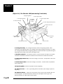
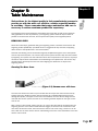
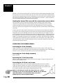
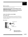
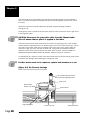
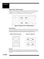
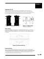
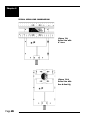
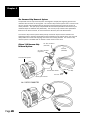
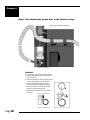
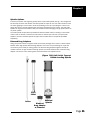
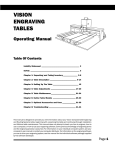
PHOENIX
ENGRAVING
TABLE
Table of
Contents
OPERATING MANUAL
Table Of Contents
Liability Statement ................................................................ 2
Safety
........................................................................... 3
Chapter 1.
Unpacking and Taking Inventory .................. 5
Chapter 2:
Table Description ........................................ 7-9
Chapter 3:
Setting Up The Table .................................... 11
Chapter 4:
Table Adjustments .................................. 13-16
Chapter 5:
Table Maintenance ................................. 17-21
Chapter 6:
Optional Accessories and Uses ........... 23-31
Chapter 7:
Troubleshooting ...................................... 33-36
This manual is designed to provide you with information about your Vision
Computerized Engraving and Routing Systems table, beginning with
unpacking the table and continuing through installation and lifetime table
maintenance. This manual does not attempt to teach you how to engrave,
how to use a computer, or how to use your engraving software. Some
previous knowledge of engraving terms and the engraving process is
assumed. For information on your individual computer system, see your
computer’s user manual or contact your computer distributor. For
information on the engraving software you use to drive your engraving
system, see the manual for the individual software package supplied by
the software developer.
Page 1
Copyright 1999 Vision Computerized Engraving & Routing Systems
(A Division of W
estern Engravers Supply
Western
Supply,, Inc.)
All Rights Reser ved
This publication is protected by copyright, and all rights are reserved. No part of this manual may be reproduced or
transmitted by any means or in any form, without prior written consent from Vision.
Limits of Liability / Disclaimer of W
ar
ranty for this T
able Manual:
War
arranty
Table
The information contained within this manual has been carefully checked and is believed to be accurate, however,
Vision makes no representations or warranties for this manual, and assumes no responsibility for inaccuracies, errors,
or omissions that may be contained within this manual. In no event shall Vision be liable for any loss of profit including
(but not limited to) direct, indirect, special, incidental, consequential, or other damages resulting from any defect or
omission in this manual, even if previously advised of the possibility of such damages.
In the interest of continued product development, Vision reserves the right to make improvements to this manual and
the products it describes at any time, without notice or obligation.
Vision Computerized Engraving and Routing Systems W
ar ranty FFor
or The Vision T
able:
War
Table:
Vision Computerized Engraving and Routing Systems warrants that for a period of one (1) year from the date of
delivery to the user of the Vision table, that the table will be free from defects in material and workmanship under
normal use and service. It is specifically understood that this warranty covers normal use only and shall be null and void
in the event that the Vision table is altered or modified by the user without authorization, or is subject to abuse,
neglect, or other misuse by the user. The spindle is covered by a ninety-day (90) warranty. Other equipment may be
purchased which is not included in this warranty, and may have a separate manufacturer’s warranty, which applies.
Other items considered “consumable”, are not covered and are excluded from any and all warranties. Specifically these
items include spindle motor brushes, spindle belts, lubricant, and cutters furnished with the table.
In the event a defect is discovered during the warranty period, the user shall contact Vision Computerized Engraving
and Routing Systems for instructions regarding resolution of the problem. Vision Computerized Engraving and Routing
Systems shall at its option, replace the Vision table or correct the defect or problem by repair at Vision’s manufacturing
facility or at one of its authorized field service offices. In the event of either replacement or repair, Vision Computerized
Engraving and Routing Systems shall be liable only for the cost of repairs, including parts and labor. Any incidental costs,
including the cost of shipment from the user’s location to the point of repair, and subsequent return, shall be at the
expense of the user. Vision Computerized Engraving and Routing Systems shall have no further liability hereunder.
Vision Computerized Engraving and Routing Systems shall have no obligation or liability to repair or replace, during the
warranty period, those items that form a part of the Vision table and are considered expendable by design, including
but not limited to, cutters, spindle motor brushes, and spindle belts.
The above and foregoing is the only warranty of any kind, either express or implied, including but not limited to any
warranties of merchantability and fitness for a particular purpose, made by Vision Computerized Engraving and Routing
Systems on the Vision table. Any warranties expressed by law are hereby expressly disclaimed. No oral or written
information, advice, or other communications given by Vision Computerized Engraving and Routing Systems, its
dealers, distributors, agents, or employees shall create a warranty or in any way increase the scope of this warranty.
Neither Vision Computerized Engraving and Routing Systems nor anyone who has ever been involved in the creation,
production, or delivery of the Vision table shall be liable for any direct, indirect, consequential, or incidental damages
(including but not limited to damages for loss of business profits, business interruption, loss of business information, and
the like) arising out of the use or inability to use this product.
Any software supplied by Vision Computerized Engraving and Routing Systems in conjunction with the purchase of the
Vision Engraving table, for use therewith, shall be governed by its own separate software license and warranty agreement.
Page 2
Safety Precautions
for The Phoenix Engraver
Safety
!Keep hands clear of the spindle belt during operation.
!Keep hands clear of the bottom of the spindle during operation.
!Always stop the machine before making any adjustments.
!Disconnect the table cable before servicing.
!Do not operate the system with covers removed.
!Wear safety glasses when cutting any materials that emit chips. Use of the optional vacuum
system will remove most chips
!Use extreme caution when inserting or removing cutters.
Page 3
Page 4
Chapter 1:
or
Unpacking and TTaking
aking In
Invvent
entor
oryy
Chapter 1
The engraving system has been shipped in more than one carton. Examine the condition of all
containers for external damage. In the event of apparent external damage, notify your carrier upon
receipt, and call your sales representative or Vision immediately.
Note: The shipping containers are considered reusable and should be stored for use in the event
of service need or upgrade.
Step 1.
Open the foam packed shipping cartons. The following items should be included:
a. The table
b. Control unit
c. Control unit accessory kit (with power strip)
d. Optional accessories you may have purchased
Check all the items in the cartons to assure they are of the correct type. Should any of the
contents be missing, damaged, or of the incorrect type, please call your sales representative
immediately.
Step 2.
Prepare a clean, level surface to put the engraving table and controller on. Carefully lift the table
and controller out of the cartons and place each on the table.
Step 3.
After unpacking the table and control unit, SAVE THE CARTONS AND FOAM PACK and
ANY OTHER BOXES. They can be reused in the event the system must be transported
to another location or returned for service. Improper packaging for shipment can
damage the table or controller and may void the warranty.
Page 5
Page 6
Chapter 2:
Table Description
Chapter 2
This chapter briefly describes the major components of the Phoenix table. Figure 2.1 shows a
labeled drawing of the Phoenix Engraver. This chapter will help you identify the parts of your table
discussed elsewhere in the manual.
*Optional equipment such as accessory vises, clamps, fixtures or vacuum systems may
our sys
or inf
ormation regar
ding this eq
uipment, see the
ha
information
regarding
equipment,
havve been included with yyour
systtem. FFor
s, com
put
er
s, and
individual ins
tructions ffor
or these op
tions. FFor
or descrip
tions of contr
oller
comput
puter
ers,
instructions
options.
descriptions
controller
ollers,
software used in your system, see the manuals from the manufacturers of these units.
TABLE SPECIFICATIONS:
Z-Axis Clearance
(definition: the distance between the bottom of the spindle and the work surface)
Phoenix Table: 3-Inches (76 mm) Clearance
e
ZAxis Str
ok
Z-Axis
Strok
oke
(definition: the travel distance of the Z-axis mechanism or spindle)
Phoenix Table: 1 Inch (25.4 mm)
Table R
esolution
Resolution
(definition: the smallest controlled motion the table is capable of)
.0005 inch on all tables (when connected by a Vision Controller)
PHOENIX
Engraving
Area
Overall
Dimensions
Table
Type
Shipping
Weight
12”x12”
21”x22”x11”
T-Slot
(non-moving)
75lbs.
DEFINITION OF TERMS (as labeled in Fig.2.1)
1. Table Base Plate. This is the large flat plate upon which everything else is mounted. All
mechanical alignments are referenced to this plate, so the space upon which you place the
engraving table must be a reasonably level surface.
2. X-Axis Linear Rails. The steel V-rails, which allow the motion of the carriage in the Xaxis direction.
3. X-Axis Stepper Motor. Drives the carriage in the X-Axis.
4. T-Slot Table. Also referred to as the work surface, this aluminum bed supported by the
linear rails allows placement of the engraving material or special clamps and fixtures. The
slots in this table are shaped with an upside-down T, with the bottom of the T being a singleline slot across the top of the table. The slots are used to hold various accessory holders,
clamps, and jigs. (A selection of various T-slot accessories appears in chapter 7.).
5. Gantry Assembly. The gantry or “bridge” is a large, rectangular bar suspended across
the width of the table in the X-axis. Supports the carriage assembly and travels along. the Yaxis.
Page 7
Chapter 2
(Figure 2.1) The Phoenix 1212 (non-moving T-slot table)
9. Engraving Motor
6. Carriage Assembly
5. Gantry Assembly
2. X-Axis Linear Rails
13. Spindle
Up/Down
Knob
3. X-Axis Stepper Motor
8. Y-Axis Stepper Motor (Dual)
10. Quick Lock Vise
8. Y-Axis Stepper
Motor (Dual)
11. Stantions
(risers)
7. Breakout Connector
4. T-Slot Table
1. Table Base Plate
6. Carriage Assembly. The carriage assembly houses the engraving spindle, Z-Axis
mechanism and engraving motor. The carriage moves along the gantry assembly on a V-Rail.
The carriage assembly holds the engraving spindle; it raises and lowers the spindle during the
engraving process using a lead screw and stepper motor.
7. Breakout Connector. This electrical access is used to connect the table to the system
controller. The breakout connector is located on the left side of the table near the back.
8. Y-Axis Stepper Motors (2). Drives the carriage in the Y-Axis. Incorporates a dual drive
mechanism.
9. X-Axis Stepper Motor. Drives the carriage in the X-Axis. Located under the protective
sheet metal cover.
10. Engraving Motor. Drives the spindle for rotary engraving.
11. Quick-Lock Vise. A “cam” type locking device that allows quick change of parts for
engraving..
12. Stantions (Risers). Larger ones are pictured in Fig.2.1.and come standard with the
Phoenix Engraver. For added clearance, shorter ones may replace these to get more
distance between the T-Slot table and the spindle.
Page 8
Chapter 2
13. Spindle Up/Down Knob. Raises and lowers head when power is off the the stepper
motor
(Figure 2.2) Current Phoenix Carriage Front view with metal covers removed
Spindle Up/Down Knob
Proximity Switch
Down Pressure Spring Adjust
Z-Axis Stepper Motor
Spindle Block
Page 9
Page 10
Chapter 3:
Se
tting U
p The TTable
able
Setting
Up
Chapter 3
Connection of Power, Cables, and Controllers
Additional boxes may have been shipped along with your table, depending on the system ordered.
These will typically include a control unit and associated cables. The proper connection of these
cables is essential. Check the appropriate user’s manuals for your controller before attempting to
connect them it to the table. After connection of the cables as directed by your controller manual,
power can be connected to the system. It is suggested that a surge protector be used. (Surge
protectors--often called “power strips” can be purchased inexpensively at your local hardware
store.) This will allow powering all of the elements of the system at once.
NOTE: Most of the newer Vision Serial Controllers include a surge protector.
(Figure 3.1) 25-pin Breakout Connector to the Vision Serial Controller
Left side view of the Phoenix Engraver
Back view of the Vision Serial Controller
Page 11
Page 12
Chapter 4:
Table A
djustments
Adjustments
Chapter 4
All Phoenix Table models include one of the following spindles:
(Figure 4.2) Top-and-Bottom
Loading Collet Spindle
(Figure 4.1) Top-Loading Spindle
12.
1.
11.
6.
2.
10.
9.
3.
8.
4.
5.
7.
1.
2.
3.
4.
5.
6.
Pulley
Spindle Housing
Micrometer
Retainer Ring
Nose cone
Draw Bar
7.
8.
9.
10.
11.
12.
Cutter
Solid Collet
Split Collet
Pointer
Cutter Knob
Cutter Knob Setscrew
Page 13
Chapter 4
Zeroing Cutters for Top-Loaded Spindles (see figure 4.1)
1. Turn the micrometer to zero. This provides a starting point and reference for setting the
depth accurately. It’s important to note that the micrometer should be threaded onto the
spindle housing sufficiently to prevent excessive play in the micrometer and nosecone. If
there are too few threads holding the micrometer in place it will move during the engraving
process. The best starting position is 3 or 4 complete revolutions from the top.
CAUTION: When you loosen the setscrew in this step, the cutter may
easily fall out of the spindle and can cause cutter tip damage. Use
one hand to hold the cutter before loosening.
2. With the appropriate cutter installed in the spindle, loosen the setscrew in the brass
cutter knob with a spline wrench (commonly referred to as the cutter wrench).
3. Gently place a piece of metal (brass preferred) against the nosecone so as to push the
cutter even with the bottom of the nosecone. Now the cutter should be flush with the
nosecone. Retighten the cutter knob setscrew. Your cutter is now zeroed. Rotating the
micrometer clockwise will adjust the depth of the cut. Each click of the micrometer = .001”.
A full revolution is .025”.
Zeroing Cutters for Top-and-Bottom-Loaded Collet Spindles (see
figure 4.2)
The collet spindle can be used for either top loaded or bottom loaded cutters. To install a top
loaded cutter in the collet spindle, first set the micrometer to zero. Loosen the knurled draw bar
on the very top of the spindle slightly. Remove the cutter knob from
the cutter, and slide the cutter into the spindle. Place a piece of flat
material against the bottom of the nosecone and lower the cutter until
it rests against the material. Tighten the draw bar around the cutter,
make sure it is tight. Then reattach the cutter knob to the top of the
cutter and screw it in counterclockwise until secure. Be careful
screwing the cutter knob in, as counterclockwise is the direction to
unscrew the draw bar (see fig 4.3). Never use pliers! The cutter
depth can be adjusted by turning the micrometer counter clockwise.
Note: If using 2" short cutters, install them from the bottom. Use the
draw bar on the very top of the spindle to tightly secure the cutter.
A solid collet, if purchased, can be installed in place of the split collet
for burnishing. Install the collet in the bottom of the spindle and
tighten the draw bar firmly. The spindle now acts as a normal top
loaded spindle for ease of operation. The split collet can be reinstalled
when required.
(Figure 4.3) Tightening the
cutter knob in the draw bar.
Page 14
Chapter 4
Diamond Engraving
To install a diamond drag adapter, remove the retainer ring and nose cone from the bottom of the
spindle and replace with the diamond drag adapter. (See fig.4.4) For diamond drag cutting, the
engraving motor is turned off and the cutter “drags” across the material. This is accomplished
with the motor on/off switch in the “off” position. Down pressure against the material can be
reduced or increased as necessary by adjusting the spindle pressure knob as described in the
next section.
(Figure 4.4) Diamond Drag Adapter
Pulley
Spindle
Housing
Micrometer
Diamond Drag
Adapter
Leveling the Phoenix Table (see fig.4.5)
All current Phoenix tables will have table level adjustments. The table may be leveled by first
loosening the 4 hex head screws that secure the t-slot table to the risers (see figure 4.5), and
then tightening or loosening the small set screws located next to the hex head screws. Once
level, the hex head screws can be re-tightened. This is a tricky process without a dial indicator to
measure accurately the run out from corner to corner. Table level adjustment can be made
without the indicator but the accuracy and time may be prohibitive.
Page 15
Chapter 4
(Figure 4.5) Front Angled View of Phoenix Table
Showing the location of hex head shoulder bolts
stantions (4)
(Figure 4.5a) Close Up
side view of a stantion
hex head shoulder bolts (4)
Replacing The Stantions For Additional Clearance (see fig.4.5 and 4.6)
This procedure will allow the user to lower the t-slot table for fixturing of taller objects. It’s
important to understand that the total Z-axis stroke does not increase, however some additional
reach can be achieved by lowering the spindle in its block.
To change from the standard 2 3/8” stantions (risers) to the shorter 1 5/8” stantions, remove the
4 shoulder bolts from the top of the t-slot table. Use a 1/8” hex key. Be careful not to strip the
bolt head when removing or replacing. After the bolts are removed, the t-slot table may be set
aside. Mark the 4 stantions as shown in fig.4.6. Keep the orientation the same when you
replace the stantions. This will ensure that the table will be level when the taller stantions are put
back in place. A flat groove has been
machined into the sides (near the top) of
the stantions (see fig.4.5a). Use a 7/8”
open end or crescent wrench to remove the
stantions by turning counterclockwise. You
can add the shorter stantions to the table
base by following the above procedure in
reverse order. Tighten the stantion in place
and replace the t-slot table. If the table is
1
2
equipped with leveling screws, you may
further level the table using the procedure
mentioned in the previous section.
(Figure 4.6) Top View of
Current Phoenix Model
Page 16
4
3
Chapter 5:
Table Maint
enance
Maintenance
Chapter 5
Vision strives for the highest quality in their manufacturing process to
provide you with the most cost effective, reliable engraving machine
in use today. Please remember that proper maintenance and care is
necessary to achieve maximum product life expectancy.
The engraving environment generates small plastic and metal chips as well as other particles
during operation. As with any machinery, your engraving system should be kept as clean as
possible to minimize wear and tear, and to improve final quality of the engraved product.
REMOVING CHIPS
Plastic and metal chips, generated during the engraving process, should be removed from the
engraving surface periodically. A portable vacuum is suggested for chip removal, but applying
direct suction to the spindle area is not recommended.
Note that this cleaning can be minimized and greatly simplified through the use of the optional
vacuum chip removal system. The vacuum chip removal system removes chips and dust created
by engraving. This system can also extend the life of other components in the system, as prompt
removal of chips reduces contamination and overheating in the spindle area. The vacuum chip
removal system also keeps the nose cone from skipping over letters due to chips on the
engraving surface.
Cleaning The Nose Cone
(Figure 5.1) Vacuum nose with hose
The nose cone around the cutter may accumulate dust and chips that cannot be removed by
sucking them off or blowing on them with low pressure air. (CAUTION! High pressure air can
damage the spindle.) Two types of nose cones are available; one nose cone is designed to be
used with the vacuum system, the other is not. Cleaning methods depend on the type of nose
cone in use.
With a vacuum chip removal system (see fig 5.1), most of the chips will be removed during the
engraving process. If the suction nozzle becomes clogged, remove the hose connection to the
nose cone. Remove the cutter, then unscrew the vacuum nose cone. Using a vacuum or an air
hose, clean out the nose and the vacuum tube leading to the nose cone. Reinstall the nose cone
and the vacuum hose.
Page 17
Chapter 5
Without a vacuum chip removal system you should remove the cutter before attempting to clean
the nose cone. The nose cone retainer ring, the nose cone, and the micrometer collar should all
be removed and cleaned using a vacuum or blowing air. The three nose cone components should
be removed and cleaned at least every day, and as frequently as necessary. Failure to clean the
nose cone regularly will result in premature spindle failure.
Cleaning the Vacuum Filter (only with the vacuum chip removal option)
On systems with a vacuum chip removal system, frequent cleaning of the vacuum filter is
necessary for proper performance. When engraving with the vacuum filter system, the filter
should be checked and cleaned several times a day, depending on the amount of engraving
done. If the vacuum does not appear to be functioning efficiently, clean the filter more frequently
as needed.
To clean the vacuum filter system, disconnect the vacuum hose from the canister. On the lid of
the canister, note the three wing nuts. Loosen these nuts enough to allow the attached bolts to
swing away from the lid, allowing removal of the lid. Do not loosen the nuts enough to remove
them completely. Remove the canister lid and inside you will find two filters. Carefully remove the
inner, paper filter. (The paper and cloth filters tend to stick together.) Empty the paper filter, and
shake it out completely, being careful not to damage it as the filters are reusable. After shaking
out the paper filter remove and empty the cloth filter in the same manner as the paper filter. Do
not wash either filter. Place the paper filter back inside the cloth filter, and place the cloth filter
back inside the vacuum canister.
LUBRICATION FOR PHOENIX MODELS
Lubricating the Z-Axis Assembly
A light amount of oil (3-in-1 preferred) should be used to coat the V-rails. Do not allow any
excess oil to accumulate on the rails since it will attract dust and engraving chips. After applying
lubricant, run the mechanism up and down the rail to evenly distribute the oil.
Lubricating the X-Axis Bridge Assembly
Same as above.
Lubricating the Y-Axis Linear Rails
Apply 2-3 drops of light oil on the rail and rub in with your fingers. XY jog the bridge back and
forth to evenly distribute the oil.
Lubricating the X-Y-Z-Axis lead screws
A light lubrication of the X and Y lead screws should be performed after every week of
usage. Use silicone lubricant only. To reach the Z-Axis lead screw, turn the spindle up/
down knob to the furthest down position, which exposes the portion of the Z lead screw
that requires lubrication. Spray a light coating along the lead screw.
HINT: To avoid having to remove the metal covers, use a nozzle
extension for your can of spray lubricant. DO NOT use any lubricant
other than silicone, as it may become sticky and cause a
buildup that can cause mechanical failure.
Page 18
Chapter 5
What not to lubricate
Many of the bearings and assemblies in your engraving machine are sealed and/or coated using
special low-friction methods and should not be lubricated.
DO NOT attempt to lubricate the spindle or the spindle bearings. If you suspect
lubrication problems, call your dealer/representative for instructions, as further
lubrication may harm the machine.
DO NOT oil the X or Y stepper motors. The only motor that requires lubrication is the
Z-motor and lead screw combination. (See lubricating the Z-axis assembly above.)
Oiling the stepper motors can permanently damage the motors.
REPAIRS, REPLACEMENTS, AND ADJUSTMENTS
How to replace a belt
A belt is used to drive the spindle engraving system. It runs between a drive pulley and the
spindle pulley. If it needs replacement, remove the old belt by rolling it to the top of the spindle
pulley, and give it a slight stretching motion to snap it off the end. Once loose, it can easily be
removed from the machine. Now position the new belt around the drive pulley, then stretch it to
snap over the top of the pulley.
Motor Brushes
Carbon Motor Brush
Threaded Brush Cap
Current Phoenix 24V Motor
(Figure 5.2) The Phoenix
engraving motor and brushes
Shown from front and side view
Page 19
Chapter 5
The motor brushes on the engraving motor should be inspected regularly, and replaced when
worn. Two brush assemblies are included with the accessories package. (One for each side of
the motor.)
Inspect the brushes for possible replacement annually using the following procedure
(see figure 5.3).
The engraving motor is located under the sheet metal top cover. Remove the cover to gain acces
to the engraving motor.
CAUTION: Disconnect the gray table cable from the Phoenix table.
This will ensure that no power is applied to the table.
Locate and remove the 4 button head screws that mount the engraving motor to the carriage.
This will allow the engraving motor to be rotated to gain access to the motor brush caps. You do
not need to remove the motor from the carriage to get to the brush caps. Simply rotate the
motor left or right 1/4 turn to fully see the brush cap. Using a flat tip screwdriver, carefully
remove the motor brush caps and inspect the carbon brush for wear. DO NOT ATTEMPT TO
SEPARATE THE MOTOR BRUSH FROM THE SPRING. Replace brushes as necessary.
To complete the job, reverse the order of the above listed steps and ensure that the motor mount
is secure to the carriage before replacing the carriage top cover.
If either brush needs to be replaced, replace both brushes as a set.
(Figure 5.3) The Phoenix Carriage
Shown from rear view with top cover removed
Spindle Up/Down Knob
(for pressure spring adjustment)
Z-Axis Limit
Button Head
Screws (x4)
Engraving Motor
Page 20
Motor Mount
Brush Cap (x2)
X-Axis Leadscrew
Chapter 5
MAINTENANCE SCHEDULE
Following is a suggested maintenance schedule. Remember that in conditions of prolonged use,
unusual environments, or unusual applications, maintenance items may need to be performed
more frequently than suggested in this schedule.
Frequency
Maintenance Items
As needed
1. Vacuum and/or brush
2. Clean vacuum canister filters
Every Day
1. Remove chips form the spindle if
you do not have a vacuum chip
removal assembly.
Every Week
1. Lubricate steel X, Y lead screws
Every Month
1. Lubricate the Z-Axis lead screw
Every Six Months
1. Check the brushes and replace if
necessary.
2. Lubricate the Z-Axis linear bearing
Page 21
Page 22
Chapter 6:
Optional Accessories and Uses
Chapter 6
Versa Vise
This low profile vise features a fixed top jaw and a moveable bottom jaw. Total opening is 3.5”.
It adapts to most systems with at least 1” clearance under the spindle. This vise is designed to
be directly mounted to many engraving tables and includes T-nuts to allow quick placement on Tslot tables. The jaws will hold a variety of clamps and jigs to secure odd shaped or difficult-tohold items.
(Figure 7.1)
Versa Vise
Universal Clamping Bars (9” Jaws)
These clamping bars are specially designed to hold both 1/16” and 1/8” thick materials and
allow engraving up to the edge of the material without nosecone interference. Other uses
include: holding metal engraving stock, name badges or other rectangular shapes. The bars will
fit the Versa Vise or can be used directly on most T-slot table surfaces. The bars will also fit
Pantographs and other computerized systems that use the dowel pin system.
(Figure 7.2) 9” Jaws
Page 23
Chapter 6
Universal Seal / Medallion Holder
This universal clamp will hold 1-3 round objects at a time. It also has a place for the “eye” of a
medallion or tag. This clamp may be used to any diameter of notary seal. These clamps will fit
the Versa Vise or can be used directly on most T-slot table surfaces. They will also fit
Pantographs and other computerized systems that use the dowel pin system.
(Figure 7.3) Universal Seal / Medallion Holder
Pen & Seal Jig
These jaws enable engraving on all types of pens and other small cylindrical objects. Rotating
the jaws 180º allows engraving on medallions, notary seals, pet tags and other round objects.
These jaws will fit the Versa Vise or can be used directly on most T-slot table surfaces. They will
also fit Pantographs and other computerized systems that use the dowel pin system.
(Figure 7.4) Pen & Seal Jig
(Figure 7.5) Seal Jig
Seal Jig
Designed for notary seals of all diameters. Rotating the jaw 180º will allow clamping of both
large and small sizes. These jaws will fit the Versa Vise or can be used directly on most T-slot
table surfaces. They will also fit Pantographs and other computerized systems that use the dowel
pin system.
Page 24
Chapter 6
Adjustable Pen Jig
Designed specially for pens and cylindrical items whose shape is not symmetrical. The
adjustment allows the capture of the small tapered diameter of pens or odd shaped items.
These jaws will fit the Versa Vise or can be used directly on most T-slot table surfaces. They will
also fit Pantographs and other computerized systems that use the dowel pin system.
(Figure 7.6) Adjustable Pen Jig
(Figure 7.7) Edge Clamp
Top view and side view
Edge Clamps
This clamp is designed to secure plastic or metal engraving stock from the top. This avoids
bowing of the material in some applications. This clamp can be moved anywhere on a T-slot
table and will hold material thicknesses of .020, .032, .062, and .125 by simply tightening a
thumbscrew.
(Figure 7.8) Universal Pin Jig
Universal Pin Jig
This is a true universal clamp designed for holding odd shaped items such as state badges,
hearts, and medallions with unusual borders, pet tags, jewelry and more. The dowel pins may be
moved anywhere on the jaw to accomodate any odd shape. These jaws will fit the Versa Vise or
can be used directly on most T-slot table surfaces. They will also fit Pantographs and other
computerized systems that use the dowel pin system.
Page 25
Chapter 6
TYPICAL VERSA VISE COMBINATIONS
(Figure 7.9)
Versa Vise with
9” Jaws
(Figure 7.10)
Versa Vise with
Pen & Seal Jig
Page 26
Chapter 6
(Figure 7.11)
Versa Vise with
Seal Jig
(Figure 7.12)
Versa Vise with
Universal Seal /
Medallion Holder
Page 27
Chapter 6
The Vacuum Chip Removal System
The optional vacuum chip removal system is designed to simplify the engraving process and
minimize wear and tear on the engraver. The vacuum chip removal system uses a vacuum nose
cone to remove chips created during the engraving process before they have the chance to
create problems. The quiet pump, coupled with the microfine-layered filters assures that your
unwanted chips are whisked away effortlessly. The vacuum pump canister uses replaceable
filters that can also be reused, to assure maximum efficiency and cost-effectiveness.
The vacuum chip removal system allows prompt removal of chips and dust created in the
engraving process, reducing contamination and overheating in the spindle area. Chip removal
also prevents the cutter from skipping over letters due to stray particles. This vacuum chip
removal system is available with or without a Vision vacuum nose cone.
(Figure 7.15) Vacuum Chip
Removal System
Vac hose connector
(small end)
Vac hose
(threaded)
Vac hose connector
(large end)
Vacuum Pump System
Vacuum filter canister
Vac nose - black
Elbow pipe connector
ALL PIECES CONNECTED
Page 28
Vac hose
(2" clear)
Chapter 6
VACUUM CHIP REMOVAL SYSTEM ASSEMBLY AND INSTALLATION
(approximate installation time = 10-15 minutes)
You should have:
1 Vacuum Pump System (silver with a box, and power cord attached)
1 Elbow pipe connector (black metal with USA stamped on it)
1 Vacuum filter canister (blue metal, with 3 wing-nut fastners)
1 Vacuum hose connector (white plastic, 2 pieces)
1 Vacuum hose (white/clear spiral, 3/4" diameter) 10'
1 Vacuum hose (clear, 2")
1 Vacuum nose (large or small)
Also included are 2 Hose
clamps (black, 3/4" +
hardware to attach vac
hose to carriage assembly.
See below for instructions.)
To assemble the vacuum pump unit:
• Examine the vacuum pump system, you will find two large screw-holes. The "in" hole is labeled
with the arrow label on the side of the vacuum pump.
• Find the elbow-pipe.
• Make sure the screw-threads are clean on both the pump system and the elbow-pipe. (Clean with
a rag and water, do not use solvents. A dirty thread can make assembling screw-in parts
significantly more difficult.)
• Screw the elbow-pipe into the pump system through the port on the side with the yellow/black
arrow label(It will not screw all the way in, make sure the elbow is tightly screwed in and will not
unscrew–some threads will show).
• Find the vacuum filter unit, and make sure the bottom thread is clean. (The bottom has three
triangle-shaped spines, and an extended "nose". The inside of the "nose" is threaded to accept the
pipe connector.)
• Screw the canister onto the vacuum pipe, making sure the canister is tightly screwed on. (The
canister will not screw in completely.)
• Check the vacuum hose connector to make sure it is clean and trimmed. Brush off any plastic
bits that may be stuck to it, and make sure the threads on the inside are clean. Seperate the two
pieces and make sure the inside is clean. (The two pieces seperate so you can remove the vacuum
hose for convienent cleaning.)
• Screw the long threaded part of the vacuum hose connector (the larger end) into the top of the
vacuum canister, making sure the hose is securely screwed in.
• Check to make sure the vacuum hose is not tangled.
The following steps may have already been done if you purchased the entire assembly together.
• Screw the vacuum input hose into the top of the vacuum hose connector (small end). The hose
has a clear plastic nozzle and a threaded end; you want to use the threaded end, it screws into the
hexagonal-part of the larger end of the white hose connector.
• Plug the clear plastic end of the vacuum hose onto the long nose that comes off the black
vacuum nose attachment. (The clear plastic will cover about half of the black vacuum nose.)
Attaching the Vacuum System to the Phoenix (see 7.14 next page)
The following items should be requested for attaching the vacuum system to the Phoenix:
•2 Plastic Clamps (5/8” for snug fit; 3/4” for loose fit)
•2 Lock Washers
•2 Screws
•1 Hex Wrench
Page 29
Chapter 6
(Figure 7.14) Attaching the Vacuum Hose to the Phoenix Carriage
Right Side of Phoenix Carriage
a
b
vacuum nose cone
To Install:
1. Remove two screws from carriage (a & b).
2. Spread apart plastic clamps (c) and place
around hose (d)
3. Place lock washer on the new longer screw
& insert through holes in the clamp (e).
4. Screw clamp (with hose inside) onto
carriage using the supplied hex wrench.
5. Put new vacuum nosecone on spindle
(adjust micrometer if needed).
6. Attach clear end of hose to new vacuum
nosecone.
d
c
Page 30
e
Chapter 6
Spindle Options
Increase your profits and engraving quality with the split collet spindle (see fig 7.15). Designed to
be extremely accurate and durable, the collet spindle is simple to use. This collet retracts around
the cutter gripping it at the bottom, while firmly holding on the top. By holding the cutter in two
places the cutter is virtually vibration-free and nearly eliminates play and runout. The split collet
spindle can engrave with excellent clarity and resolution while averaging a longer product life than
any other spindle.
The collet spindle accepts both top loaded and bottom loaded cutters, including 2" short shank
cutters such as drill bits, router bits, dremel tools etc. Should you ever want your split collet
spindle to act like a standard spindle, simply install our solid collet in the spindle (available
separately).
Diamond Drag Adapters
Using your plastic cutters to engrave metal can seriously damage them. There is a better option;
Western offers high-quality diamond drag adapters. Don’t burn out your bearings on a job that
can be done just as easily as cutting plastic. The diamond drag adapter engraves virtually allmetallic surfaces, at high resolution and high speed. The results achieved with a diamond drag
adapter can be even more amazing when used with double- and triple-line fonts.
(Figure 7.15) Split Collet Top-andBottom Loading Spindle
Split
Collet
Cutter
Standard
Spindle
Diamond
Drag Adapter
w/ Diamond
Page 31
Page 32
Chapter 7:
Troubleshooting
Chapter 7
ENGRAVING PROBLEMS
Problem: Engraving on the plate is “slanted”.
Possible solutions:
1. Check material for squareness. Maybe your shear does not cut squarely.
2. Check to see if the material on the table is indeed at a true home and is square to your scale
bars or stops.
3. If your table is equipped with scale bars insure that they are secure and flush to your T-Slot
table.
Hint: Always inspect your job before removing your plate from the system. You may be able to
salvage it by re-engraving the job, or at a minimum, you may be able to analyze the problem and
prevent repeating it. Perhaps the plate moved during engraving. Removing it without inspection
would prevent you from detecting this problem.
Problem: You are using a nosecone, but your engraving is “shallow” across the top or left
margin of your plate. It engraves properly when the spindle is away from the edge.
Possible solutions:
1. Your nosecone is riding on the scale bars or side stops. Loosen and
lower the scale bars so that they are below the level of your material
surface. Retighten the thumbscrews.
2. Check to see if your material is riding on the scale bars or side stops. It’s not hard to miss
during set-up especially if the plate is thin material.
Problem: You are using a nosecone and your engraving is uneven.
Possible solutions:
1. Your spindle is not “zeroed” to your material. Follow the steps in “Chapter 4” to zero your
spindle.
2. You are not using enough float and need to adjust the down stroke until your nosecone
touches the material with some pressure.
3. You may be engraving too fast for the type of material you are cutting. Check the
manufacturer’s recommendation. The cutter may be bouncing on the surface. Some hard
materials may exhibit this problem.
4. You may have a defective or broken cutter. Replace it.
5. Your material may be defective.
6. Your vac chip removal system is plugged and engraving chips are caught between the
nosecone and the material.
7. The nosecone or vac nose is loose.
Problem: “Shadowing” occurs while engraving certain materials.
Possible solutions:
1. Leave the protective film on the engraving material during engraving.
2. Use a plastic nosecone instead of a metal one.
3. The nosecone may be damaged. Inspect for burrs or roughness. Try using an emory cloth to
polish the nose.
4. Back off on the spring pressure. Excessive down pressure will leave a rub mark on almost any
plastic material.
Page 33
Chapter 7
Problem: You are not using a nosecone and you have uneven engraving.
Possible solutions:
1. Switch to a nose-riding method.
2. Use a different method of holding the material. If you use double sided tape, it may be thick
enough to change your surface flatness by a few thousandths.
3. Parcel the job if possible so that you can have more direct control over the depth of each
specific area. This may be effective if you have uneven material or a large engraving bed.
4. Table tolerances may not be able to maintain the accuracy level you want.
5. Table may not be on a level surface.
Hint: While it’s true that you can do non-nose riding engraving, it’s not easy to hold any
controlled accuracy on the depth. This takes flat material, a very flat bed and some degree of skill
and confidence. It also takes an application where some amount of uneven engraving may be
tolerated.
Problem: I’m getting “tails” or “swirls” in the corners of my engraving.
Possible solutions:
1. Your cutter speed is too fast relative to your x-y speed. Slow your spindle speed down or
increase your table speed.
2. Your cutter is worn or damaged. Replace.
3. Turn down the dwell speed.
Problem: I’m getting “fuzz”, “fur” or can see lines in the bottom of my cut showing each
cutter path. I can even see steps in the bottom of my cut.
Possible solutions:
1. This problem is tough. Sometimes caused by dull cutters, the wrong cutter, or not enough
overlap for each cut. Try changing cutter size slightly. You may get better clean up.
2. Try taking a second pass cut at .001-.002 deeper. This may clean up the roughness.
3. Resharpen the cutter. There are various cutter angles that can cause these kinds of problems.
There is a relief angle that if too great can cause noticeable ridges in the bottom of the cut.
4. Ensure that the spindle is square in the mount or block. An unsquare spindle means an
unsquare cutter to the material surface.
5. Turn spindle speed up.
Problem: Poor letter quality.
Possible solutions:
1. You may be engraving too fast. Engraving quality improves with the right engraving and spindle
speeds.
2. If you are diamond drag engraving, you have too much down pressure or you are engraving too
deep. Also, check the grain of the material; it should be left to right.
3. You may have a worn or dull cutter.
4. Your material is not securely fastened to the table.
Probelm: Ragged Type.
Possible solutions:
1. If the quality of cut is ragged or exhibits steps, you may have play in the cutter.
Page 34
Chapter 7
This could be in the gap between the cutter and the spindle shaft. Maybe the shaft is worn or the
spindle bearings need to be replaced. Once a shaft starts to wear and a cutter is loose, the
problem can worsen quickly.
2. The spindle is loose in the housing or block.
3. The carriage is loose or has excessive play, check the z-axis bearings or slide.
4. Lubricate lead screws with recommended lubricant.
Problem: My baseline is off.
Possible solutions:
1. You’re not at the mechanical or software home. Maybe the table or carriage was bumped
during set-up. Maybe the previous job was cut short and the system did not return back to its
mechanical home or limit switches. Move the table, bridge or carriage physically to home or send
it home via the software.
2. Check your software layout for keystroke errors.
Problem: While burnishing aluminum I have voids or non-engraved areas.
Possible solutions:
1. Try re-engraving the same plate again. Some of the anodized aluminum plates have very hard
surfaces and two passes are required.
2. Switch to a diamond burnisher. The more common carbide tools may have difficulty getting
through the tough surface and are more easily worn down, thus sometimes skipping across the
surface.
3. Increase the pressure of the z-axis or burnishing adaptor.
4. Try other materials. Same reasons as above. Some materials, from some vendors, are just
plain tough.
Hints:
Always try to solve the problems yourself before seeking help. A little patience goes a long way.
Never work on any problem that gets you so frustrated that you become irritated at the machine,
the service technician, or the salesman. It’s only a machine, don’t let it get the best of you.
Contact your dealer.
MECHANICAL PROBLEMS
Problem: No X, Y or Z-Axis movement.
Possible solutions:
1. Check that the controller power is on.
2. Check that the drives are turned on.
3. Check the table cable for a solid connection. It may be helpful to remove the cable, reconnect
and tighten the hold down screws to ensure a good connection.
4. Ensure that the job has been transferred to the controller (Green start light is ON).
5. Ensure that the emergency STOP button is not depressed, then turn the drives on.
Page 35
Chapter 7
Problem: System has no movement in any one axis.
Possible solutions:
1. Try to jog the problem axis using the X/Y/Z jog keys on the control unit. If OK, retry the job.
2. Check the table cable for a solid connection.
3. Call service technician for further instructions.
Problem: Unusually loud noises during the engraving process.
Possible solutions:
1. Isolate the cause of the unusual noise by:
a. Remove the cutter.
b. Turn the engraving motor to OFF.
c. Run the engraving job, or X/Y jog the system.
If the noise persists, it may be confined to the X, Y or Z-axis. Check for proper lubrication of lead
screws. Follow lubrication instructions in chapter 5.
If the noise goes away and to further isolate the cause, do the following:
a. Remove the motor belt.
b. Run the engraving motor without starting a job. Loose motor belts may cause some
noises, so removal will narrow down the problem. If the noise is present with the
spindle motor on, check the motor brushes.
If there is no unusual noise when running the spindle motor with no belt attached, do the following:
a. Attach the motor belt.
b. Run the spindle motor and vary the RPM by changing the control unit potentiometer.
Noise levels may vary. If the noise persists, check the spindle for overheating.
Excessive overheating of the outside housing of the spindle is a sign of defective
bearings. The noise may be caused by the bearings.
Problem: Spindle is hot.
Possible solutions:
1. Ensure that the nose cone area is free of debris. Check the vacuum system (if used) for clogging.
2. Inspect the spindle for other obstructions that may prevent proper rotation.
3. Bearings may need to be replaced.
Problem: Spindle motor will not come on.
Possible solutions:
1. Check the auto/on/off switch to ensure the proper operational mode.
2. Check motor brushes.
Problem: Motor belt will not stay on pulley.
Possible solutions:
1. Motor belt is probably worn and needs to be replaced.
Page 36