1
2008
MOTORCYCLE
SERVICE MANUAL
Model : YW50X_
5PNF81972100 *5PNF81972100*
FORWORD
This supplementary service manual has been prepared to introduce new service and data for YW50BP
2001. For complete service manual procedures it is necessary to use this supplementary service
manual together with the following manual.
YW50BP 2001 SERVICE MANUAL : 5PN1-ME1
EAS00000
YW50X 2007
SUPPLEMENTARY SERVICE MANUAL
©2007 by Yamaha Motor Taiwan Co., Ltd.
First edition, June 2007
All rights reserved.
Any reproduction or unauthorized use
without the written permission of
Yamaha Motor Taiwan Co., Ltd.
is expressly prohibited.
Printed in CANADA
EAS00002
NOTICE
This manual was produced by the Yamaha Motor Taiwan Company, Ltd. primarily for use by Yamaha
dealers and their qualified mechanics. It is not possible to include all the knowledge of a mechanic in
one manual. Therefore, anyone who uses this book to perform maintenance and repairs on Yamaha
vehicles should have a basic understanding of mechanics and the techniques to repair these types
of vehicles. Repair and maintenance work attempted by anyone without this knowledge is likely to
render the vehicle unsafe and unfit for use.
Yamaha Motor Taiwan Company, Ltd. is continually striving to improve all of its models. Modifications
and significant changes in specifications or procedures will be forwarded to all authorized Yamaha
dealers and will appear in future editions of this manual where applicable.
NOTE:
Designs and specifications are subject to change without notice.
EAS00005
IMPORTANT MANUAL INFORMATION
Particularly important information is distinguished in this manual by the following.
Q
The Safety Alert Symbol means ATTENTION! BECOME ALERT! YOUR
SAFETY IS INVOLVED!
w
Failure to follow WARNING instructions could result in severe injury or death
to the scooter operator, a bystander or a person checking or repairing the
scooter.
cC
A CAUTION indicates special precautions that must be taken to avoid damage to the scooter.
NOTE:
A NOTE provides key information to make procedures easier or clearer.
EAS00007
HOW TO USE THIS MANUAL
This manual is intended as a handy, easy-to-read reference book for the mechanic. Comprehensive
explanations of all installation, removal, disassembly, assembly, repair and check procedures are
laid out with the individual steps in sequential order.
1 The manual is divided into chapters. An abbreviation and symbol in the upper right corner of
each page indicate the current chapter.
Refer to “SYMBOLS”.
2 Each chapter is divided into sections. The current section title is shown at the top of each page,
except in Chapter 3 (“PERIODIC CHECKS AND ADJUSTMENTS”), where the sub-section
title(s) appears.
3 Sub-section titles appear in smaller print than the section title.
4 To help identify parts and clarify procedure steps, there are exploded diagrams at the start of
each removal and disassembly section.
5 Numbers are given in the order of the jobs in the exploded diagram. A circled number indicates
a disassembly step.
6 Symbols indicate parts to be lubricated or replaced.
Refer to “SYMBOLS”.
7 A job instruction chart accompanies the exploded diagram, providing the order of jobs, names of
parts, notes in jobs, etc.
8 Jobs requiring more information (such as special tools and technical data) are described sequentially.
6
2
1
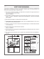
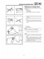
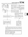
CYLINDER HEAD, CYLINDER AND PISTON ENG
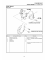
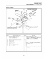
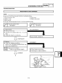
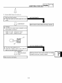
CYLINDER HEAD, CYLINDER, PISTON
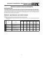
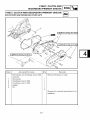
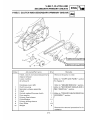
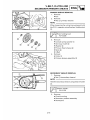
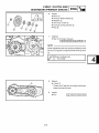
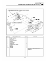
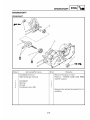
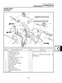
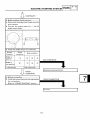
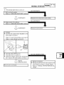
CYLINDER HEAD, CYLINDER AND PISTON
CYLINDER HEAD, CYLINDER AND PISTON
3
T.
R.
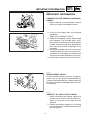
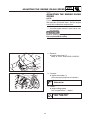
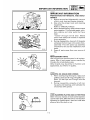
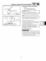
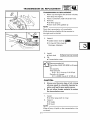
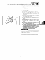
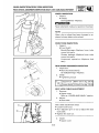
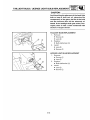
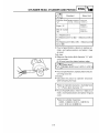
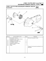
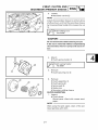
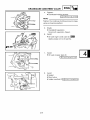
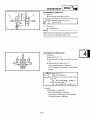
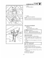
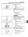
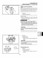
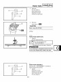
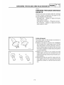
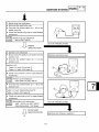
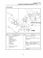
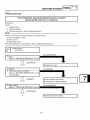
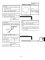
Before removing the piston pin clip, cover the
crankcase with a clean rag so you will not accidentally drop the clip into the crankcase.
26Nm(2.6 m.kg, 18.2 ft.lb)
4
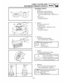
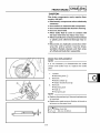
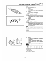
2. Remove:
8 Piston pin 1
8 Piston 2
8 Piston pin bearing 3
10 New 1
5
New
4
ENG
PISTON PIN AND PISTON REMOVAL
1. Remove:
8 Piston pin clip 1
NOTE:
cC
5
Do not use a hammer to drive the piston pin
out.
3
6
New
T.
R.
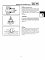
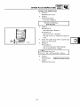
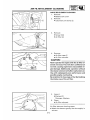
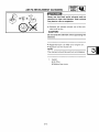
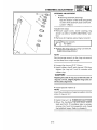
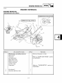
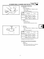
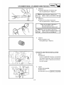
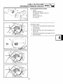
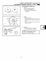
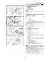
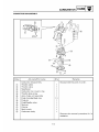
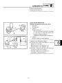
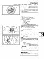
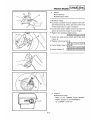
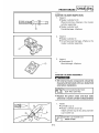
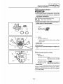
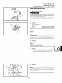
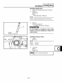
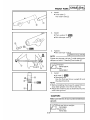
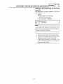
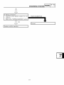
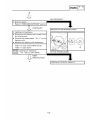
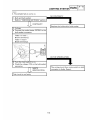
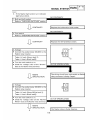
CYLINDER HEAD INSPECTION
1. Eliminate:
8 Carbon deposits
Use a rounded scrapper 1.
9Nm(0.9 m.kg,6.5 ft.lb)
T.
R.
14Nm(1.4 m.kg, 10 ft.lb)
8
2
7
9
E
7
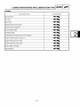
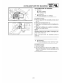
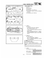
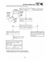
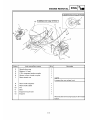
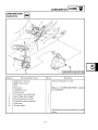
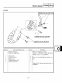
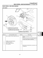
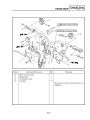
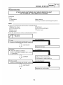
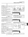
Order
1
2
3
4
5
6
7
8
9
10
Job name/Part name
Q’ty
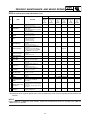
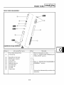
Cylinder head, Cylinder and piston
removal
Engine
Muffler/Gasket
Air shroud 2
Spark plug
Cylinder head/Cylinder head gasket
Cylinder
Piston pin clip
Piston pin/ Bearing
Piston
Piston ring set
Cylinder gasket
Remarks
Remove the parts in the order.
1/1
1
1
1/1
1
2
1/1
1
1
1
Refer to the “ENGINE REMOVAL” section
2
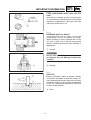
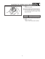
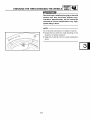
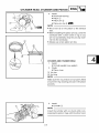
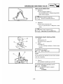
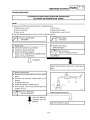
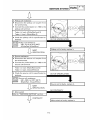
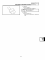
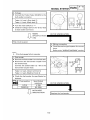
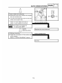
2. Inspect:
8 Cylinder head warpage
Out of specification∅Re-surface.
*************************************
Warpage measurement and re-surfacement
steps:
8 Attach a straight edge 1 and a thickness
gauge 2 on the cylinder head.
8 Measure the warpage limit.
Warpage limit:
0.03 mm(0.0012 in)
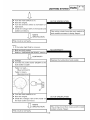
8 If the warpage is out of specification, reface
the cylinder head.
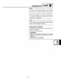
NOTE:
Reverse the removal procedure for installation.
4-3
1
Rotate the head severai tires to avoid removing too much material from one side.
4-4 * * * * * * * * * * * * * * * * * * * * * * * * * * * * * * * * * * * * *
8
EAS00008
1
2
GEN
INFO
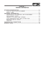
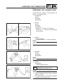
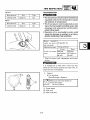
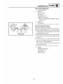
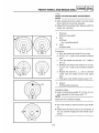
SYMBOLS
The following symbols are not relevant to every
vehicle.
Symbols 1 to 9 indicate the subject of each
chapter.
SPEC
3
4
CHK
ADJ
1
2
3
4
5
6
7
8
9
CHAS
5
6
ENG
COOL
7
8
CARB
ELEC
9
0
-
+
Symbols 0 to u indicate the following.
0 Serviceable with engine mounted
q Filling fluid
w Lubricant
e Special tool
r Tightening torque
t Wear limit, clearance
y Engine speed
u Electrical data
TRBL
SHTG
q
w
e
r
General information
Specifications
Periodic checks and adjustments
Chassis
Engine
Cooling system
Carburetor
Electrical system
Troubleshooting
T.
R.
t
y
o
i
4
p
G
d
s
u
B
M
f
BF
g
M
LS
h
a
S
j
LT
New
Symbols i to g in the exploded diagrams indicate the types of lubricants and lubrication
points.
i Engine oil
o Gear oil
p Molybdenum-disulfide oil
a Brake fluid
s Wheel-bearing grease
d Lithium-soap- based grease
f Molybdenum-disulfide grease
g Silicone grease
Symbols h to j in the exploded diagrams indicate the following.
h Apply locking agent (LOCTITE®)
j Replace the part
EAS00010
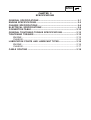
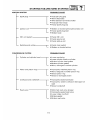
TABLE OF CONTENTS
GENERAL INFORMATION
SPECIFICATIONS
PERIODIC CHECKS AND
ADJUSTMENTS
CARBURETOR
GEN
INFO
1
SPEC
2
CHK
ADJ
3
CARB
4
5
6
5
7
8
9
GEN
INFO
CHAPTER 1
GENERAL INFORMATION
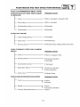
SCOOTER IDENTIFICATION ................................................................... 1-1
VEHICLE IDENTIFICATION NUMBER ............................................. 1-1
MODEL LABEL .................................................................................. 1-1
IMPORTANT INFORMATION ................................................................... 1-2
PREPARATION FOR REMOVAL AND DISASSEMBLY ................... 1-2
REPLACEMENT PARTS ................................................................... 1-2
GASKETS, OIL SEALS AND O-RINGS ............................................ 1-2
LOCK WASHERS/PLATES AND COTTER PINS ............................. 1-3
BEARINGS AND OIL SEALS ............................................................ 1-3
CIRCLIPS ........................................................................................... 1-3
CHECKING THE CONNECTIONS ........................................................... 1-4
SPECIAL TOOLS ...................................................................................... 1-5
1-8
SCOOTER IDENTIFICATION
GEN
INFO
EAS00015
GENERAL INFORMATION
SCOOTER IDENTIFICATION
1
EAS00017
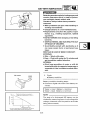
VEHICLE IDENTIFICATION NUMBER
The vehicle identification number 1 is stamped
into the frame.
EAS00018
MODEL LABEL
The model label 1 is affixed to the seat. This
information will be needed to order spare parts.
1
1-1
IMPORTANT INFORMATION
GEN
INFO
EAS00020
IMPORTANT INFORMATION
PREPARATION FOR REMOVAL AND DISASSEMBLY
1. Before removal and disassembly, remove
all dirt, mud, dust and foreign material.
2. Use only the proper tools and cleaning
equipment.
Refer to the “SPECIAL TOOLS”.
3. When disassembling, always keep mated
parts together. This includes gears, cylinders, pistons and other parts that have been
“mated” through normal wear. Mated parts
must always be reused or replaced as an
assembly.
4. During disassembly, clean all of the parts
and place them in trays in the order of disassembly. This will speed up assembly and
allow for the correct installation of all parts.
5. Keep all parts away from any source of fire.
EAS00021
REPLACEMENT PARTS
Use only genuine Yamaha parts for all replacements. Use oil and grease recommended by
Yamaha for all lubrication jobs. Other brands may
be similar in function and appearance, but inferior in quality.
EAS00022
GASKETS, OIL SEALS AND O-RINGS
1. When overhauling the engine, replace all
gaskets, seals and O-rings. All gasket surfaces, oil seal lips and O-rings must be
cleaned.
2. During reassembly, properly oil all mating
parts and bearings and lubricate the oil seal
lips with grease.
1-2
IMPORTANT INFORMATION
GEN
INFO
EAS00023
LOCK WASHERS/PLATES AND COTTER
PINS
After removal, replace all lock washers/plates
1 and cotter pins. After the bolt or nut has been
tightened to specification, bend the lock tabs
along a flat of the bolt or nut.
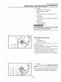
EAS00024
BEARINGS AND OIL SEALS
Install bearings and oil seals so that the
manufacturer’s marks or numbers are visible.
When installing oil seals, lubricate the oil seal
lips with a light coat of lithium-soap-based
grease. Oil bearings liberally when installing, if
appropriate.
1 Oil seal
cC
Do not spin the bearing with compressed
air because this will damage the bearing
surfaces.
1 Bearing
EAS00025
CIRCLIPS
Before reassembly, check all circlips carefully
and replace damaged or distorted circlips. Always replace piston pin clips after one use. When
installing a circlip 1, make sure the sharp-edged
corner 2 is positioned opposite the thrust 3
that the circlip receives.
4 Shaft
1-3
CHECKING THE CONNECTIONS
GEN
INFO
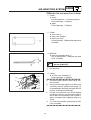
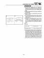
EAS00026
CHECKING THE CONNECTIONS
Check the leads, couplers, and connectors for
stains, rust, moisture, etc.
1. Disconnect:
8 lead
8 coupler
8 connector
2. Check:
8 lead
8 coupler
8 connector
Moisture i Dry with an air blower.
Rust/stains i Connect and disconnect
several times.
3. Check:
8 all connections
Loose connection i Connect properly.
NOTE:
If the pin 1 on the terminal is flattened, bend it
up.
4. Connect:
8 lead
8 coupler
8 connector
NOTE:
Make sure all connections are tight.
5. Check:
8 continuity
(with the pocket tester)
Pocket tester
90890-03112(YU-03112-C)
NOTE:
8 If there is no continuity, clean the terminals.
8 When checking the wire harness, perform
steps (1) to (3).
8 As a quick remedy, use a contact revitalizer
available at most part stores.
1-4
SPECIAL TOOLS
GEN
INFO
EAS00027
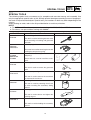
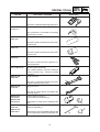
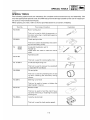
SPECIAL TOOLS
The following special tools are necessary for complete and accurate tune-up and assembly. Use
only the appropriate special tools as this will help prevent damage caused by the use of inappropriate tools or improvised techniques. Special tools, part numbers or both may differ depending on the
country.
When placing an order, refer to the list provided below to avoid any mistakes.
NOTE:
8 For U.S.A. and Canada, use part number starting with “YM-”, “YU-”, or “ACC-”.
8 For others, use part number starting with “90890-”.
Tool NO.
90890-01235
YU-01235
90890-01337
YM-33285
YM-33285-6
90890-01284
YU-90050
90890-01383
YU-90062
90890-01189
YU-01189
90890-01135
YU-01135-B
90890-01384
YM-33299
90890-01403
YU-A9472
90890-01701
YS-01880-A
Tool name / Function
Illustration
Rotor holding tool
This tool is used to hold the generator rotor
when removing or installing and generator
rotor bolt.
Clutch spring holder
These tool are used for removing the nut with
holding the compression spring.
Crankshaft installer set 1
Adapter 2
These tools are used to install the crankshaft.
Flywheel puller
This tool is used to remove the generator
rotor.
Crankcase separating tool
This tool is used to remove the crankshaft
or separate the crankcase.
Oil seal guide
This tool is used for protecting the oil seal
lip when installing the secondary sliding
sheave.
Steering nut wrench
This tool is used to loosen and tighten the
steering ring nut.
Sheave holder
This tool is used for holding the secondary
sheave.
1-5
1
2
SPECIAL TOOLS
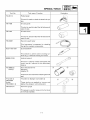
Tool NO.
90890-06760
90890-03112
YU-03112-C
90890-01409
YM-01409
90890-01410
YM-01410
90890-06754
YM-34487
90890-85505
ACC-11001-05-01
90890-01348
YM-01348
90890-01268
YU-01268
90890-01367
YM-A9409-7
90890-01400
YM-A9409-3
90890-01326
YM-01326
90890-01294
YM-01300-1
Tool name / Function
GEN
INFO
Illustration
Digital tachometer
This tool is needed for detecting engine rpm.
Pocket tester
This instrument is invaluable for checking
the electrical system.
Oil seal guide
This tool is used to install the left side crankcase oil seal.
Oil seal installer
This tool is used to install the left side crankcase oil seal.
Ignition checker
This tool is used to check the ignition system components.
Yamaha bond NO.1215
Sealant (Quick Gasket ®)
This sealant (bond) is used on crankcase
mating surfaces (e.g., crankcase mating
surfaces).
Locknut wrench
This tool is used when removing or installing the secondary sheave nut.
Ring nut wrench
41
46
This tool is used to loosen and tighten the
steering ring nut.
Fork seal driver weight 1
Fork seal driver attachment 2
These tools are used when installing the fork
seal.
T-handle 1
Damper rod holder 2
These tools are used to hold the damper rod
when removing or installing the damper rod.
1-6
1
1
2
2
SPECIAL TOOLS
Tool NO.
90890-01312
YM-01312-A
Tool name / Function
Fuel level gauge
This gauge is used to measure the fuel lever in the float chamber.
1-7
GEN
INFO
Illustration
SPEC
CHAPTER 2
SPECIFICATIONS
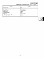
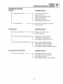
GENERAL SPECIFICATIONS ................................................................. 2-1
ENGINE SPECIFICATIONS ..................................................................... 2-2
CHASSIS SPECIFICATIONS ................................................................... 2-6
ELECTRICAL SPECIFICATIONS ............................................................ 2-9
CONVERTION TABLE ............................................................................ 2-12
GENERAL TIGHTENING TORQUE SPECIFICATIONS ....................... 2-12
TIGHTENING TORQUES........................................................................ 2-13
ENGINE ............................................................................................ 2-13
CHASSIS .......................................................................................... 2-14
LUBRICATION POINTS AND LUBRICANT TYPES ............................. 2-16
ENGINE ............................................................................................ 2-16
CHASSIS .......................................................................................... 2-17
CABLE ROUTING .................................................................................. 2-18
2-23
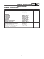
GENERAL SPECIFICATIONS
SPEC
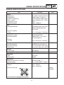
SPECIFICATIONS
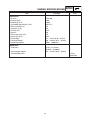
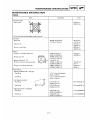
GENERAL SPECIFICATIONS
Standard
Item
Model
Code
Dimensions
Overall length
Overall width
Overall height
Seat height
Wheelbase
Minimum ground clearance
Minimum turning radius
Weight
Wet (without oil and a full fuel tank)
Dry (without oil and fuel)
Maximun load (total of cargo, rider,
passenger, and accessories)
Limit
5PJ5 (USA)
5PN6 (CAN)
…
…
1890mm (74.41in)
705mm (27.76in)
1110mm (43.70in)
765mm (30.12in)
1275mm (50.20in)
120mm (4.72in)
1800mm (70.87in)
…
…
…
…
…
…
…
94kg (207lb)
90kg (198lb)
143kg (315lb)
…
…
…
2-1
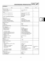
ENGINE SPECIFICATIONS
SPEC
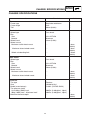
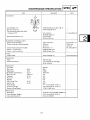
ENGINE SPECIFICATIONS
Standard
Item
Engine
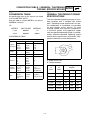
Engine type
Displacement
Cylinder arrangement
Bore × stroke
Compression ratio
Engine idle speed
Fuel
Recommended fuel
Fuel tank capacity
Total
Engine oil
Lubrication system
Recommended oil
Quantity
Oil tank
Air-cooled 2-stroke reed valve
0.049L (49cm³, 2.99cu-in)
Forward inclined single cylinder
40.0 × 39.2mm (1.57 × 1.54in)
7.01:1
1800 ~ 1900r/min
Limit
…
…
…
…
…
…
Unleaded gasoline only (USA) …
Regular unleaded gasoline
…
only (CAN)
5.7L (1.25 Imp gal, 1.50 US gal) …
Separate lubrication
YAMALUBE 2 or air cooled
2-stroke engine oil
…
…
1.4L (1.23 Imp qt, 1.48 US qt)
…
Final gear oil
Recommended oil
Periodic oil change
Total amount
SAE85W140 hypoid gear oil
…
0.11L (0.10 Imp qt, 0.12 US qt) …
0.13L (0.12 Imp qt, 0.14 US qt) …
Air filter
Air filter type
Wet element
…
Starting system type
Electric and kick starter
…
Carburetor
Type
Manufacturer
Y14P-13E
TEIKEI
…
…
Spark plug
Model (manufacturer) × quantity
Spark plug gap
BPR7HS (NGK ) × 1
…
0.6 ~ 0.7mm (0.024 ~ 0.028in) …
Cylinder head
Volume
Maximum warpage
5.54 ~ 5.84cm³
(0.34 ~ 0.36cu-in)
…
* Lines indicate straighedge measurement
2-2
…
0.05mm
(0.0020in)
ENGINE SPECIFICATIONS
Standard
Item
Cylinder
Bore
Maximum taper
40.000 ~ 40.014mm
(1.5748 ~ 1.5754in)
…
Maximum out-of-round
…
Piston
Piston-to-cylinder clearance
Diameter D
H
Height H
Piston pin bore (in the piston)
Diameter
Piston pin
Outside diameter
Piston rings
Section sketch (B × T)/type
Top ring
2nd ring
End gap (installed)
Top ring
2nd ring
Side clearance (installed)
Top ring
2nd ring
Connecting rod
Connecting rod length
Small end inside diameter
SPEC
D
Limit
…
0.05mm
(0.0020in)
0.05mm
(0.0020in)
0.035 ~ 0.040mm
(0.0014 ~ 0.0016in)
39.960 ~ 39.979mm
(1.5732 ~ 1.5739in)
5.0mm (0.1969in)
0.10mm
(0.0039in)
…
10.004 ~ 10.015mm
(0.3939 ~ 0.3943in)
10.045mm
(0.3955in)
9.996 ~ 10.000mm
(0.3935 ~ 0.3937in)
9.976mm
(0.3928in)
1.2 × 1.6mm/keystone
(0.0472 × 0.0630in)
1.2 × 1.6mm/keystone
(0.0472 × 0.0630in)
…
…
…
0.15 ~ 0.35mm
(0.0059 ~ 0.0138in)
0.15 ~ 0.35mm
(0.0059 ~ 0.0138in)
0.6mm
(0.0236in)
0.7mm
(0.0276in)
0.03 ~ 0.05mm
(0.0012 ~ 0.0020in)
0.03 ~ 0.05mm
(0.0012 ~ 0.0020in)
0.1mm
(0.0039in)
0.11mm
(0.0043in)
79.9~80.1mm
(3.1457~3.1535in)
13.996~14.007mm
(0.5510~0.5515in)
…
2-3
…
ENGINE SPECIFICATIONS
SPEC
Standard
Item
Limit
Crankshaft
Width “A”
Maximum runout “C”
Big end side clearance “D”
Big end radial clearance
Small end free play “F”
Clutch
Clutch type
Clutch shoe thickness
37.90 ~ 37.95mm
(1.4921 ~ 1.4941in)
…
0.20 ~ 0.50mm
(0.0079 ~ 0.0197in)
0.004 ~ 0.017mm
(0.0002 ~ 0.0007in)
0.40 ~ 0.80mm
(0.0157 ~ 0.0315in)
Automatic centrifugal
2.5mm (0.10in)
Clutch shoe spring free length
Clutch housing inside diameter
26.2mm (1.03in)
105mm (4.13in)
Compression spring free length
65.1mm (2.56in)
Weight outside diameter
15.0mm (0.59in)
Clutch - in revolution
Clutch - stall revolution
2800 ~ 3200r/min
4500 ~ 5500r/min
V-belt
V-belt width
Kickstarter
Type
Kick clip tension
Transmission
Transmission type
Primary reduction system
Primary reduction ratio
Secondary reduction system
Secondary reduction ratio
Single speed automatic
Maximum main axle runout
Maximum drive axle runout
…
0.03mm
(0.0012in)
1.00mm
(0.0394in)
…
…
…
1.0mm
(0.04in)
…
105.5mm
(4.15in)
61.8mm
(2.43in)
14.5mm
(0.57in)
…
…
16.5mm (0.65in)
14.8mm
(0.58in)
Ratchet
0.7 ~ 2N (0.07 ~ 0.2kgf)
(0.15 ~ 0.44lb)
…
…
V-belt automatic
Helical gear
52/13 (4.000)
Super gear
43/13(3.307)
2.693 ~ 0.889:1
…
…
…
…
…
…
…
0.02mm
(0.0008in)
0.02mm
(0.0008in)
…
2-4
ENGINE SPECIFICATIONS
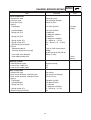
Standard
Item
Carburetor
ID mark
Main jet (M.J.)
Needle jet (N.J.)
Jet needle-clip position (J.N.)
Main air jet (M.A.J.)
Cutaway (C.A.)
Pilot jet (P.J.)
Bypass
Valve seat size (V.S.)
Starter jet (St.J.)
Float height
Fuel level height
Engine idle speed
Reed valve
Thickness
Valve stopper height
Valve bending limit
SPEC
5PJ5 00
# 80
2.085
3N24-1/1
2.0
3.0
# 44
0.8
1.8
0.45
15 ~ 17mm (0.59 ~ 0.67in)
3.0 ~ 4.0mm (0.12 ~ 0.16in)
1800 ~ 1900r/min
0.132 ~ 0.172mm
(0.0052 ~ 0.0068in)
5.9 ~ 6.5mm (0.23 ~ 0.26in)
…
2-5
Limit
…
…
…
…
…
…
…
…
…
…
…
…
…
…
…
0.2mm
(0.0078in)
CHASSIS SPECIFICATIONS
SPEC
CHASSIS SPECIFICATIONS
Standard
Item
Frame
Frame type
Caster angle
Trail
Front wheel
Wheel type
Rim
Size
Material
Wheel travel
Wheel runout
Maximum radial wheel runout
Maximum lateral wheel runout
Wheel axle bending limit
Rear wheel
Wheel type
Rim
Size
Material
Wheel travel
Wheel runout
Maximum radial wheel runout
Maximum lateral wheel runout
Front tire
Tire type
Size
Model (manufacturer)
Tire pressure (cold)
Up to 90kg (198lb) load
90kg (198lb) load ~ Maximum load*
Minimum tire tread depth
Limit
Steel tube underbone
26.5°
93mm (3.66in)
…
…
…
Cast wheel
…
J10 × MT3.50
Aluminum
61mm (2.40in)
…
…
…
…
1.0mm
(0.04in)
1.0mm
(0.04in)
0.45mm
(0.02in)
…
…
Cast wheel
…
J10 × MT3.50
Aluminum
76mm (2.99in)
…
…
…
…
1.0mm
(0.04in)
0.5mm
(0.02in)
…
Tubeless
120/90-10 56J
C-6022 (CHENG SHIN)
…
…
…
200kPa (2.00kgf/cm², 29psi)
200kPa (2.00kgf/cm², 29psi)
…
…
…
0.8mm
(0.03in)
2-6
CHASSIS SPECIFICATIONS
Standard
Item
Rear tire
Tire type
Size
Model (manufacturer)
Tire pressure (cold)
Up to 90kg (198lb) load
90kg (198lb) load ~ Maximum load*
Minimum tire tread depth
SPEC
Limit
Tubeless
130/90-10 59J
C-924 (CHENG SHIN)
…
…
…
200kPa (2.00kgf/cm², 29psi)
200kPa (2.00kgf/cm², 29psi)
…
…
…
0.8mm
(0.03in)
Pad thickness
Single disk brake
Right-hand operation
180 × 4.0mm
(7.09 × 0.16in)
4.0mm (0.16in)
Master cylinder inside diameter
Caliper cylinder inside diameter
Brake fluid type
11mm (0.43in)
30.16mm (1.19in)
DOT 4 or DOT3
…
…
180 × 3.5mm
(7.09 × 0.14in)
0.8mm
(0.03in)
…
…
…
Front brake
Brake type
Operation
Disk outside diameter × thickness
Rear brake
Brake type
Operation
Brake drum inside diameter
Lining thickness
Brake lever
Brake lever free play (front lever end)
Brake lever free play (rear lever end)
Throttle cable free play
Drum brake
Left-hand operation
130mm (5.12in)
4.0mm (0.16in)
2 ~ 5mm (0.08 ~ 0.20in)
10 ~ 20mm (0.39 ~ 0.79in)
1.5 ~ 3.5mm (0.06 ~ 0.14in)
2-7
…
…
131mm
(5.16in)
2.0mm
(0.08in)
…
…
…
CHASSIS SPECIFICATIONS
Standard
Item
Front suspension
Suspension type
Front fork type
Front fork travel
Spring
Free length
Installed length
Spring rate (K1)
Spring rate (K2)
Spring stroke (K1)
Spring stroke (K2)
Optional spring available
Fork oil
Recommended oil
Quantity (each front fork leg)
Inner tube outer diameter
Inner tube bending limit
Steering system
Steering bearing type
Lock-to-lock angle (left)
Lock-to-lock angle (right)
Rear suspension
Suspension type
Rear shock absorber assembly type
Rear shock absorber assembly travel
Spring
Free length
Installed length
Spring rate (K1)
Spring stroke (K1)
Optional spring available
SPEC
Limit
Telescopic fork
Coil spring/oil damper
70mm (2.76in)
…
…
…
217.1mm (8.55in)
212.8mm
(8.38in)
…
…
212.1mm (8.35in)
15.69N/mm
(1.60kg/mm, 90lb/in)
23.8N/mm
(2.43kg/mm, 136lb/in)
0 ~ 40mm (0 ~ 1.57in)
40 ~ 70mm (1.57 ~ 2.76in)
No
Fork oil 10W or equivalent
0.088L
(0.084 Imp qt, 0.092 US qt)
30mm (1.18in)
…
…
…
…
…
…
…
…
0.2mm
(0.01in)
Angular bearing
45°
45°
…
…
…
Unit swing
Coil spring / oil damper
55mm (2.17in)
…
…
…
159.8mm (6.29in)
152.8mm (6.02in)
71.15N/mm
(7.26kg/mm, 407lb/in)
0 ~ 55mm (0 ~ 2.17in)
No
…
…
…
2-8
…
…
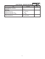
ELECTRICAL SPECIFICATIONS
SPEC
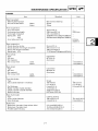
ELECTRICAL SPECIFICATIONS
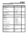
Standard
Item
System voltage
Limit
12V
…
C.D.I.
14° BTDC at 5000r/min
Fixed
400 ~ 600Ωat 20°C (68°F)/
black - white/red
5PJ (T-MORIC)
…
…
…
…
…
Ignition coil
Model (manufacturer)
Minimum ignition spark gap
Primary coil resistance
Secondary coil resistance
2JN (T-MORIC)
6mm (0.24in)
0.184 ~ 0.276Ω at 20°C (68°F)
6.32 ~ 9.48kΩ at 20°C (68°F)
…
…
…
…
Spark plug cap
Material
Resistance
Resin
4 ~ 6kΩ at 20°C (68°F)
…
…
AC magneto
F5PJ (T-MORIC)
12V 85W/5000r/min
0.6A at 3000r/min
1.2A at 8000r/min
0.48 ~ 0.72Ω/white - black
12V at 3000r/min
15V at 8000r/min
0.4 ~ 0.6Ω/yellow/red - black
640 ~ 960Ω at 20°C (68°F)/
black - black/red
…
…
…
…
…
…
…
…
…
…
Rectifier
Model (manufacturer)
No load regulated voltage (DC)
No load regulated voltage (AC)
Rectifier capacity
Withstand voltage
SH614-12 (SHIN DEN GEN)
14 ~ 15V
13 ~ 14V
8A
18V
…
…
…
…
…
Battery
Battery type (manufacturer)
Battery voltage/capacity
Specific gravity
Ten hour rate amperage
GTX5L-BS (GS)
12V/4AH
1.330
0.4A
…
…
…
…
Ignition system
Ignition system type
Ignition timing
Advancer type
Pick coil resistance/color
C.D.I. unit model (manufacturer)
Charging system
System type
Model (manufacturer)
Nominal output
Charging current
Charging coil resistance/color
Lighting voltage
Lighting coil resistance/color
Source coil resistance/color
2-9
ELECTRICAL SPECIFICATIONS
SPEC
Standard
Item
Limit
Headlight type
Halogen bulb
…
Indicator light (voltage/wattage × quantity)
Turn signal indicator light
High beam indicator light
Oil level indicator light
12V 1.7W × 1
12V 1.7W × 1
12V 1.7W × 1
…
…
…
Bulbs (voltage/wattage × quantity)
Headlight
Tail/brake light
Front turn signal light
Rear turn signal light
License plate light
Speedometer light
12V 35/35W × 1
12V 5/21W × 1
12V 10W × 2
12V 10W × 2
12V 5W × 1
12V 3.4W × 1, 1.7W × 1
…
…
…
…
…
…
Constant mesh
…
4WX 01 (SHINLIN)
12V
0.14kW
…
…
…
6.5mm (0.26in)
3.0mm
(0.12in)
…
Electric starting system
System type
Starter motor
Model (manufacturer)
Suction voltage
Power output
Brushes
Overall length
Spring force
Commutator diameter
Armature coil resistance
Mica undercut (depth)
5.49 ~ 8.24N
(360 ~ 540gf, 12.69 ~ 19.04oz)
16.1mm (0.63in)
15.1mm
(0.59in)
0.063 ~ 0.077Ω at 20°C (68°F) …
1.05mm (0.04in)
…
Starter relay
Model (manufacturer)
Amperage
Coil resistance
4WX 00 (SHINLIN)
20A
54 ~ 66Ω
…
…
…
Horn
Horn type
Model (manufacturer)
Maximum amperage
Performance
Coil resistance
Plane
AH-368 (SAKURA)
1.5A
95 ~ 105dB/2m
4.05 ~ 4.55Ω at 20°C (68°F)
…
…
…
…
…
Turn signal relay
Relay type
Model (manufacturer)
Self-cancelling device built-in
Turn signal blinking frequency
Wattage
Condenser
5PJ1 (TAYOUNG)
NO
75 ~ 95cycles/minute
10W × 2 + 1.7W+ AP
…
…
…
…
…
2-10
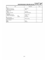
ELECTRICAL SPECIFICATIONS
SPEC
Standard
Item
Limit
Fuse (amperage × quantity)
Main fuse
7A × 1
…
Fuel sender
Model (manufacturer)
Sender unit resistance - full
Sender unit resistance - empty
4VP (TATUNG)
4 ~ 10Ω
90 ~ 100Ω
…
…
…
Oil lever gauge
Model (manufacturer)
4VP (LUN PING)
…
2-11
CONVERTION TABLE / GENERAL TIGHTENING
TORQUE SPECIFICATIONS
SPEC
EAS00028
EAS00030
CONVERSION TABLE
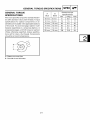
GENERAL TIGHTENING TORQUE
SPECIFICATIONS
All specification data in this manual are listed
in SI and METRIC UNITS.
Use this table to convert METRIC unit data to
IMPERIAL unit data.
This chart specifies tightening torques for standard fasteners with a standard ISO thread
pitch. Tightening torque specifications for special components or assemblies are provided
for each chapter of this manual. To avoid
warpage, tighten multi-fastener assemblies in
a crisscross pattern and progressive stages
until the specified tightening torque is reached.
Unless otherwise specified, tightening torque
specifications require clean, dry threads. Components should be at room temperature.
Ex.
METRIC
MULTIPLIER
IMPERIAL
** mm
0.03937
** in
2 mm
0.03937
0.08 in
CONVERSION TABLE
METRIC TO IMPERIAL
Metric unit
m·kg
Tightening torque m·kg
cm·kg
cm·kg
Multiplier
Imperial unit
7.233
86.794
0.0723
0.8679
ft·lb
in·lb
ft·lb
in·lb
Weight
kg
g
2.205
0.03527
lb
oz
Speed
km/hr
0.6214
mph
Distance
km
m
m
cm
mm
0.6214
3.281
1.094
0.3937
0.03937
mi
ft
yd
in
in
Volume/
Capacity
cc (cm3)
cc (cm3)
lt (liter)
lt (liter)
0.03527
0.06102
0.8799
0.2199
oz (IMP liq.)
cu-in
qt (IMP liq.)
gal (IMP liq.)
kg/mm
kg/cm2
Centigrade
(°C)
55.997
14.2234
9/5+32
lb/in
psi (lb/in2)
Fahrenheit (°F)
Misc.
A: Width across flats
B: Thread diameter
2-12
A
(nut)
B
(bolt)
10 mm
General tightening
torques
Nm
m•kg
ft•lb
6 mm
6
0.6
4.3
12 mm
8 mm
15
1.5
11
14 mm
10 mm
30
3.0
22
17 mm
12 mm
55
5.5
40
19 mm
14 mm
85
8.5
61
22 mm
16 mm
130
13.0
94
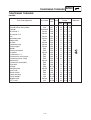
TIGHTENING TORQUES
SPEC
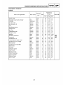
TIGHTENING TORQUES
ENGINE
Part to be tightened
Part name
Thread ’
Q ty
size
Tightening
torque
Remarks
Nm m•kg ft•lb
Spark plug
Cylinder head and cylinder
Cylinder
Air shroud 1
Air shroud 1× 2
Fan
Autolube pump
Reed valve
Air filter
Carburetor cap
Exhaust pipe
Muffler
Exhaust protector
Protector
Crankcase 1× 2
Transmission case cover
Crankcase cover 1(left)
Bolt(case2)
Crankcase cover2(left)
Drain bolt
Oil plug
Idle gear plate
Kick crank
Starter motor
Clutch housing
Clutch weight
Magnet base
C.D.I. rotor
—
Nut
Stud bolt
Screw
Screw
Screw
Screw
Bolt
Screw
Screw
Screw
Bolt
Bolt
Screw
Bolt
Bolt
Bolt
Screw
Bolt
Bolt
Plug
Screw
Bolt
Bolt
Nut
Nut
Screw
Nut
2-13
M 14
M7
M7
M6
6.0
M6
M5
M6
M6
M4
M6
M8
M6
M6
M6
M6
M6
M6
M6
M8
M 14
M6
M6
M6
M 10
M 10
M6
M 10
1
4
4
3
1
3
2
4
2
2
2
2
3
1
6
6
12
1
3
1
1
2
1
2
1
1
2
1
20
14
10
7
2
7
4
11
9
2
9
26
11
9
12
12
12
7
7
18
3
8
9
13
40
30
8
38
2.0 14
1.4 10
7
1.0
0.7 5.1
0.2 1.4
0.7 5.1
0.4 2.8
1.1 8.0
0.9 6.5
0.2 1.4
0.9 6.5
2.6 18.2
1.1 8.0
0.9 6.5
1.2 8.4
1.2 8.4
1.2 8.4
0.7 5.1
0.7 5.1
1.8 13
0.3 22
0.8 5.8
0.9 6.5
1.3 9.4
4.0 29
3.0 22
0.8 5.8
3.8 27
LT
LT
TIGHTENING TORQUES
SPEC
CHASSIS
Part to be tightened
Thread
size
Tightening
torque
Nm
M 12
M 10
M6
M 10
M8
M 25
M 10
M8
M6
M6
M5
M6
M6
M5
M6
M 10
M 14
M6
M8
M10
M8
M5
Frame and engine bracket
Engine bracket, compression rod and engine
Rear carrier
Rear shock absorber and frame
Rear shock absorber and engine
Steering ring nut
Handle holder and steering shaft
Brake hose and master cylinder
Fuel tank
Fuel cock
Fuel sender
Box
Seat lock assembly
Plastic parts & cover
Footrest board
Front wheel axle and nut
Rear wheel axle and nut
Rear brake cam lever
Front brake caliper and front fork
Brake disc and hub
Brake hose and caliper
Brake caliper and bleed screw
2-14
Remarks
m•kg ft•lb
84
45
13
30
16
8.4
4.5
1.3
3.0
1.6
61
31
9.4
22
12
60
20
10
7
4
7
7
2
7
70
120
10
23
20
23
6
6.0
2.0
1.0
0.7
0.4
0.7
0.7
0.2
0.7
7.0
12.0
1.0
2.3
2.0
2.3
0.6
43.4
14
7
5.1
2.9
5.1
5.1
1.4
5.1
51
87
7.2
16.6
14.5
16.6
4.3
See “NOTE”
LT
TIGHTENING TORQUES
SPEC
NOTE :
1. First, tighten the ring nut(lower) approximately 38Nm(3.8m•kg, 27.5ft•lb) by using the torque
wrench, then loosen the ring nut 1/4 turn.
2. Second, tighten the ring nut(lower) approximately 12Nm(1.2m•kg, 8.7ft•lb) by using the torque
wrench.
3. Installing the rubber washer.
4. Then finger tighten the center ring nut and touch rubber washer. Align the slots both ring nut and
install the lock washer.
5. Final, hold the ring nuts(lower and center) and tighten the ring nut(upper) 75Nm(7.5m•kg, 54.2ft•lb)
by using the torque wrench.
6. Confirm, adjust the direction handlebar to the right direction, front wheel suspended. Push direction handlebar lightly with the finger (approximately 1.5kgf • cm), direction handlebar should
turn slowly without interference or hindrance.
1
2
3
4
5
2-15
Lower ring nut
Rubber washer
Center ring nut
Lock washer
Upper ring nut
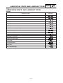
LUBRICATION POINTS AND LUBRICANT TYPES
SPEC
EAS00031
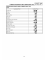
LUBRICATION POINTS AND LUBRICANT TYPES
ENGINE
Lubrication Point
Lubricant
Oil seal lips
LS
O-rings
LS
Bearings
E
Piston surface
E
Piston pin
E
Cylinder
E
Transmission case (bearing)
G
Autolube pump
LS
Starter wheel gear
LS
Idle gear plate
M
Secondary drive gear
G
Kickstarter pinion gear
LS
Drive axle
M
Pump drive gear
LS
Main axle
G
Main axle (bearing)
G
2-16
LUBRICATION POINTS AND LUBRICANT TYPES
SPEC
EAS00032
CHASSIS
Lubrication Point
Lubricant
Oil seal lips
LS
O-rings
LS
Bearings
LS
Speedometer drive gear
LS
Front brake lever pivot shaft
S
Rear brake lever pivot shaft
LS
Front brake camshaft
LS
Front brake cable
LS
Throttle cable
LS
Tube guide (throttle grip) inner surface
LS
Upper steering stem ring nut
LS
Upper bearing outer race
LS
Lower bearing outer race
LS
Rear brake camshaft
LS
Centerstand
LS
2-17
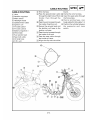
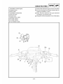
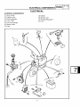
CABLE ROUTING
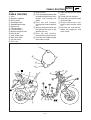
t Wire harness
A Pass the speedometer cable
through the right hole of front
fender, then through the
guide.
B Pass the wire harness
through the inside of ignition
coil.
C Secure the ground lead and
the ignition coil base to the
ignition coil stay.
D Pass the wire harness
through the inside of oil tank.
E Pass the seat cable through
the inside of frame.
EAS00035
CABLE ROUTING
1 Horn
2 Rectifier regulator
3 Main switch
4 Headlight leads
5 Speedometer cable
6 Ignition coil
7 Throttle cable 1
8 Throttle cable 3
9 Battery negative lead
0 Wire brake
q Fuel sender lead
w Seat lock cable
e Oil tank hose
r C.D.I. unit
SPEC
F Align the clip with the white
brand.
G Clamp the wire harness.
H Insert the seat cable through
the frame tube.
I Clamp wireharness, rear
brake cable throttle cable
1,3.
J Position the cylinder between the supporter and
main switch.
0
8
7
q
1
w
e
r
3
2
4
q
8
7 9 6
2-18
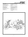
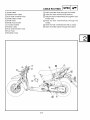
CABLE ROUTING
1 Brake cable
2 Speedometer cable
3 Fuel tank overflow hose
4 Brake cable holder
5 Brake hose
6 Brake hose holder
7 License bracket
8 Flasher relay
9 Fuel tank breather hose
0 Fuel hose
q Breather hose
A Pass the brake hose through
the holder.
B Insert the fuel overflowhose
bottom.
C Pass the fuel overflowhose
through the rear fender hole.
D Pass the fuel overflowhose
through the holder.
E Hold the fuel overflowhose
with a clamp.
F Pass the brake cable through
the holder.
3
1
5
9
2
8
SPEC
q
6
0
7
4
2-19
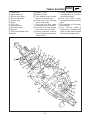
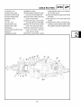
CABLE ROUTING
1 Brake hose
2 Front fender
3 Front fork assembly
4 Nut
5 Plate washer
6 Brake hose holder 1
7 Flange bolt
8 Brake hose holder 2
9 Bolt
0 Grommet
q Flange bolt
w Brake hose holder
e Brake hose holder 3
SPEC
A Tighting torque:3.5 ~ 5.5Nm.
B Assemble the brake hose
holder 3 hang hook must certainty hook the brake hose
holder.
C Tighting torque:8.5 ~ 14Nm.
D Tighting torque:3.5 ~ 5Nm.
E Tighting torque:3.5 ~ 5.5Nm.
F Pass the brake hose through
the brake hose holder.
q
w
e
F
2
1
q
B
3
5
0
1
4
9A
3
E9
8
3
5
C4
2-20
7D
5
6
6
5
CABLE ROUTING
1 Ignition coil
2 Spark plug lead
3 Starter relay leads
4 Auto choke leads
5 Starter relay
6 Band
7 C.D.I. unit
8 Autolube hose
9 Seat lock cable
0 Bracket
q Fuel tank breather hose
w Band 2
e Battery - lead
r Battery + lead
A Pass battery leads through
the slot of footrestboard.
B Cover them after securing
starter relay leads.
C Pass the seat lock cable
through the hole of bracket.
D Pass the fuel tank breath
hose over seat lock cable.
E Clamp carburetor vacuum
hose, fuel hose and fuel cock
vacuum hose.
SPEC
F Clamp autochoke leads and
autolube hose on to carburetor throttle cable.
G Pass the batter y leads
through the forward of cross
pipe.
H Put fuse box on to footrest
board holder.
I Pass throttle cable1,3
wireharness, autolube pump
cable, brake cable through
the outside of battery box.
1
A
2
B 3
I
4
5
6
H
r
7
e
8
G
F
9
0
C
w
E
D
q
2-21
CABLE ROUTING
1 Grip assembly
2 Handlebar switch(right)
3 Front brake light switch
4 Speedometer
5 Rear brake cable
6 Handlebar switch(left)
7 Grip
8 Handlebar assembly
9 Wire harness
0 Throttle cable 1
q Throttle cable 3
w Speedometer cable
e Brake hose
A Route the front brake light
switch lead through between
the handlebar pipe and the
brake hose.
B Route the front brake light
switch lead, left handlebar
switch lead and front turn signal light lead through the
backward of speedometer
cable .
C Route the front turn signal
light lead through the slot of
handlebar bracket and
through the backward of rear
brake cable.
D Route the left handlebar
switch lead through the backward of handlebar pipe.
E Fasten the throttle cables,
brake hose, wire harness,
speedometer cable and rear
brake cable to the frame and
cut the end to be shorter than
5mm and reserve for a finger clearance, the position on
the above of guide wire and
align white point mark of wire
harness.
SPEC
F Route the speedometer
cable through between the
frame and the brake hose to
right side.
G Route the throttle cable1,3
through between the handlebar, wire harness and brake
hose to left side.
H Connect the couplers securely in rear of the brake
hose.
I Pass the throttle cable1,3
through the hole in the
handlebar cover1.
J After adjusting the throttle
cable free play, insert into the
boots.
K After tightening must has
clearance, and tightening
torque 60Nm(6.0m • kg,
43.4ft • lb).
9
K
e
w
B
5 0 q
3
4
C
A
5 6
2
1
q
0
J
8
I H
E
G
F
9
2-22
D
7
CHK
ADJ
CHAPTER 3
PERIODIC CHECKS AND ADJUSTMENTS
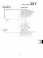
INTRODUCTION ....................................................................................... 3-1
PERIODIC MAINTENANCE AND MINOR REPAIR ................................ 3-1
Periodic maintenance chart for the emission control system ........... 3-1
General maintenance and lubrication chart...................................... 3-2
COVER AND PANEL ................................................................................ 3-4
SEAT AND SIDE COVERS................................................................ 3-4
LOWER COWLING, UPPER COVER AND LEG SHIELD 1 ............ 3-5
LEG SHIELD 2 AND FOOTREST BOARD ....................................... 3-6
HANDLEBAR COVER(FRONT AND REAR) .................................... 3-7
ADJUSTING THE ENGINE IDLING SPEED ........................................... 3-8
3-10
INTRODUCTION/PERIODIC MAINTENANCE AND
MINOR REPAIR
CHK
ADJ
EAS00036
PERIODIC CHECKS AND ADJUSTMENTS
INTRODUCTION
This chapter includes all information necessary to perform recommended checks and adjustments.
If followed, these preventive maintenance procedures will ensure more reliable vehicle operation, a
longer service life and reduce the need for costly overhaul work. This information applies to vehicles
already in service as well as to new vehicles that are being prepared for sale. All service technicians
should be familiar with this entire chapter.
EAS00037
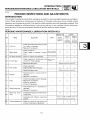
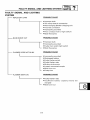
PERIODIC MAINTENANCE AND MINOR REPAIR
EAU17570
Periodic maintenance chart for the emission control system
* Since these items require special tools, data and technical skills, have a Yamaha dealer perform
the service.
INITIAL
NO.
ITEM
ROUTINE
1,000 km
(600 mi)
or
1
month
ODOMETER READING
4,000 km
(2,000 mi)
or
6
months
7,000 km
(4,000 mi)
or
12
months
10,000km
(6,000 mi)
or
18
months
13,000 km 16,000 km
(8,000 mi) (10,000 mi))
or
or
24
30
months
months
1
* Fuel line
• Check fuel and vacuum hoses for
cracks or damage.
• Replace if necessary.
2
* Idle speed
• Check and adjust engine idle
speed.
3
* Exhaust system
• Check for leakage.
• Tighten if necessary.
• Replace gasket(s) if necessary.
4
* Air induction system
• Check the air cut-off valve, reed
valve, and hose for damage.
• Replace any damaged parts.
3-1
PERIODIC MAINTENANCE AND MINOR REPAIR
CHK
ADJ
EAU32115
General maintenance and lubrication chart
INITIAL
NO.
ITEM
ROUTINE
1,000 km
(600 mi)
or
1
month
ODOMETER READING
4,000 km
(2,000 mi)
or
6
months
7,000 km
(4,000 mi)
or
12
months
10,000km
(6,000 mi)
or
18
months
13,000 km 16,000 km
(8,000 mi) (10,000 mi))
or
or
24
30
months
months
* Air filter element
• Clean with solvent.
• Replace if necessary.
2
* Front brake
• Check operation, fluid level, and for
fluid leakage.
• Replace brake pads if necessary.
3
* Rear brake
• Check operation.
• Adjust cable and replace brake
shoes if necessary.
4
* Wheels
• Check runout and for damage.
• Replace if necessary.
5
* Tires
• Check tread depth and for damage.
• Replace if necessary.
• Check air pressure.
• Correct if necessary.
6
* Wheel bearings
• Check bearings for smooth
operation.
• Replace if necessary.
7
* Steering bearings
• Check bearing assemblies for
looseness.
• Moderately repack with lithiumsoap-based grease every 16000
km (10000 mi) or 18 months.
Repack.
8
* Chassis fasteners
• Check all chassis fitting and
fasteners.
• Correct if necessary.
1
9
Front brake lever
pivot shaft
• Apply silicone grease lightly.
10
Rear brake lever
pivot shaft
• Apply lithium-soap-based grease
(all-purpose grease) lightly.
11
Centerstand
• Check operation.
• Lubricate.
• Check operation and for oil
leakage.
• Replace if necessary.
12
* Front fork
13
* assembly
• Check operation and for oil
leakage.
• Replace if necessary.
14
* Autolube pump
• Check operation.
• Bleed if necessary.
• Check vehicle for oil leakage.
• Change.
Shock absorber
Final transmission
oil
15
16
17
* V-belt
Control and meter
* cables
Throttle grip housing
and cable
18
*
19
* switches
Lights, signals and
• Replace.
• Apply Yamaha chain and cable
lube or engine oil 10W-30
thoroughly.
Every 10000 km(6250 mi)
• Check operation and free play.
• Adjust the throttle cable free play if
necessary.
• Lubricate the throttle grip housing
and cable.
• Check operation.
• Adjust headlight beam.
* Since these items require special tools, data and technical skills, have a Yamaha dealer perform the
service.
NOTE:
From 19000 km (12000 mi) or 36 months, repeat the maintenance intervals starting from 7000 km
(4000 mi) or 12 months.
3-2
PERIODIC MAINTENANCE AND MINOR REPAIR
CHK
ADJ
EAU17620
NOTE:
● The air filter needs more frequent service if you are riding in unusually wet or dusty areas.
● Hydraulic brake system
•
When disassembling the master cylinder or caliper cylinder, always replace the
brake fluid. Check the brake fluid level regularly and fill as required.
•
Replace the oil seals on the inner parts of the master cylinder and caliper cylinder
every two years.
•
Replace the brake hoses every four years or if cracked or damaged.
3-3
COVER AND PANEL
CHK
ADJ
EAS00038
COVER AND PANEL
SEAT AND SIDE COVERS
13Nm (1.3 m•kg, 9.4 ft•lb)
4
2
5
3
7
8
1
6
Order
1
2
3
4
5
6
7
8
Job/Part
Q’ty
Removing the seat and side covers
Battery box cover
Seat
Seat hanger
Rear carrier
Rear cover
Side cover(left)
Side cover(right)
Center cover
1
1
1
1
1
1
1
1
Remarks
Remove the parts in the order listed.
NOTE:
Insert the (-) screwdriver into the slot of
battery box cover and pickup then remove.
For installation, reverse the removal procedure.
3-4
COVER AND PANEL
CHK
ADJ
LOWER COWLING, UPPER COVER AND LEG SHIELD 1
4
3
2
5
1
Order
Job/Part
Q’ty
1
2
3
4
5
Removing the lower cowling, upper
cover, and leg shield 1
Lower cowling
Head light lead coupler(low)
Head light lead coupler(high)
Upper cover
Leg shield 1
Remarks
Remove the parts in the order listed.
1
1
1
1
1
Disconnect.
Disconnect.
For installation, reverse the removal procedure.
3-5
COVER AND PANEL
CHK
ADJ
LEG SHIELD 2 AND FOOTREST BOARD
1
7Nm (0.7 m•kg, 5.1 ft•lb)
5
2
6
7
4
3
8
Order
Job/Part
Q’ty
Removing the leg shield 2 and footrest board
Leg shield 1
1
2
3
4
5
6
7
8
Remove the parts in the order listed.
Refer to “LOWER COWLING, UPPER
COVER AND LEG SHIELD 1”.
1
1
1
1
1
1
1
1
Main switch cover
Leg shield 2
Footrest(left)
Footrest(right)
Battery negative lead
Battery positive lead
Battery
Footrest board
Remarks
w
First, disconnect the battery negative
lead, and then the battery positive lead.
For installation, reverse the removal procedure.
3-6
COVER AND PANEL
CHK
ADJ
HANDLEBAR COVER(FRONT AND REAR)
3
2
1
Order
Job/Part
Q’ty
1
2
3
Removing the handlebar cover(front
and rear)
Handlebar cover(front)
Speedometer cable
Handlebar cover(rear)
Remarks
Remove the parts in the order listed.
1
1
1
Disconnect.
For installation, reverse the removal procedure.
3-7
ADJUSTING THE ENGINE IDLING SPEED
CHK
ADJ
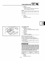
EAS00054
ADJUSTING THE ENGINE IDLING
SPEED
NOTE:
Prior to adjusting the engine idling speed, the air
filter element should be clean, and the engine
should have adequate compression.
1. Start the engine and let it warm up for several minutes.
w
Before starting the engine, be sure to use
the centerstand for safety.
2. Remove:
8 battery box cover 1
Refer to “SEAT AND SIDE COVERS”.
1
3. Connect:
8 digital tachometer 1
(onto the spark plug lead of cylinder )
1
Digital tachometer
90890-06760
4. Check:
8 engine idling speed
Out of specification i Adjust
Engine idling speed
1800 ~ 1900 r/min
3-8
ADJUSTING THE ENGINE IDLING SPEED
b
CHK
ADJ
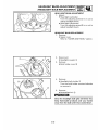
5. Adjust:
8engine idling speed
a
▼▼▼▼▼▼▼▼▼▼▼▼▼▼▼▼▼▼▼▼▼▼▼
a. Turn the throttle stop screw 1 in direction
a or b until the specified engine idling
speed is obtained.
1
Direction a
Direction b
Engine idling speed is increased.
Engine idling speed is decreased.
▲▲▲▲▲▲▲▲▲▲▲▲▲▲▲▲▲▲▲▲▲▲▲
6 . Install:
8 battery box cover
Refer to “SEAT AND SIDE COVERS”.
3-9
CARB
CHAPTER 4
CARBURETOR
AIR INDUCTION SYSTEM ....................................................................... 4-1
AIR FILTER CASE ASSEMBLY ......................................................... 4-1
CHECKING THE AIR INDUCTION SYSTEM ................................... 4-3
4-4
AIR INDUCTION SYSTEM
CARB
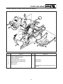
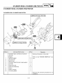
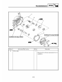
AIR INDUCTION SYSTEM
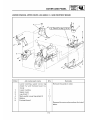
AIR FILTER CASE ASSEMBLY
2
1
3
Order
Job/Part
Q’ty
1
2
3
Removing the air filter case assembly
Hose(to air filter)
Pipe(to exhaust pipe)
Air filter case assembly
Remarks
Remove the parts in the order listed.
1
1
1
Disconnect.
Disconnect.
For installation, reverse the removal procedure.
4-1
AIR INDUCTION SYSTEM
CARB
8
1
9
2
0
q
3
w
4
5
7
6
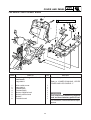
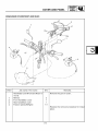
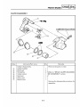
Order
Job/Part
Q’ty
1
2
3
4
5
6
7
8
9
0
q
w
Disassembling the air filter case assembly
Cap
Damper
Air filter case cap
Reed valve
Reed valve stopper
Reed valve seat
Reed valve assembly
Element
Plate
O-ring
Air filter case body
Damper
4-2
Remarks
Remove the parts in the order listed.
1
1
1
1
1
1
1
1
1
1
1
For assembly, reverse the disassembly
procedure.
AIR INDUCTION SYSTEM
CARB
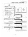
EAS00510
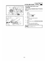
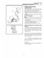
CHECKING THE AIR INDUCTION SYSTEM
1. Check:
8 hoses
Loose connection i Connect properly.
Cracks/damage i Replace.
8 pipes
Cracks/damage i Replace.
2. Check:
8 reed valve 1
8 reed valve stopper
8 reed valve seat
Cracks/damage i Replace the reed valve
assembly.
3. Measure:
8 reed valve bending limit a
Out of specification i Replace the reed
valve assembly.
Reed valve bending limit
0.2 mm (0.0078 in)
1 Surface plate
4. Check:
8 air filter case assembly 1
Cracks/damage i Replace.
▼▼▼▼▼▼▼▼▼▼▼▼▼▼▼▼▼▼▼▼▼▼▼
a. Start the engine and let it warm up for several minutes.
b. Dismount the intake tube 2 of air filter case
assembly, and put a piece of thin paper 3
at the opening of the body, the paper will not
pulsate (sucking and releasing).
c. If there is no pulsation, turn off the engine
and check if there is any leakage or clog in
the air filter case assembly or not. If there if,
repair and repeat the inspection steps in a
and b.
d. If it is still not pulsating, replace the air filter
case assembly.
▲▲▲▲▲▲▲▲▲▲▲▲▲▲▲▲▲▲▲▲▲▲▲
1
3
2
4-3
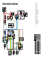
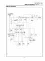
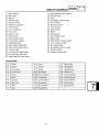
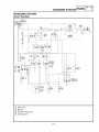
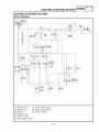
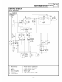
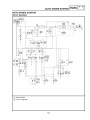
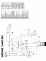
YW50X WIRING DIAGRAM
1
LOCK
OPEN
OFF
CHECK
ON
0
(GREEN)
6
8
9
7
2
q
12V 7A
4
5
(BLACK)(BLACK)
3
n
m
,
1
2
3
4
5
6
7
8
9
0
q
w
e
r
t
y
u
i
o
p
a
s
d
f
g
h
j
k
l
;
z
x
c
v
b
n
m
,
Main switch
Main fuse
Battery
Starter relay
Starter motor
Rectifier/regulator
Auto choke
C.D.I. magneto
C.D.I. Unit
Ignition coil
Spark plug
Front brake light switch
Rear brake light switch
Tail/brake light
Rear turn signal light(left)
Rear turn signal light(right)
License plate light
Front turn signal light(right)
Front turn signal light(left)
Headlight(high)
Headlight(low)
Turn signal relay
Horn
Handlebar switch(left)
Horn switch
Dimmer switch
Turn signal switch
Fuel sender
Speedometer
Fuel gauge
Oil level indicator light
Speedometer light
High beam indicator light
Turn signal indicator light
Oil lever gauge
Handlebar switch(right)
Engine stop switch
Start switch
OFF
START
d
b
s
(BLACK)
f
h
g
j
MARK
(RED)
z
;
12V 1.7W BEAM
CONNECTING WITH GRD. WIRE
12V 1.7W TURN
(RED)
EXPLANATION
R, Br, BrW... COLOR CODE
x c
w
GRD.
e
A, B, C,
(RED) (RED)
v
(RED)
k
r
u
(GREEN) (GREEN)
B
(RED)
12V 1.7W OIL
l
12V 3.4W ILUMI
OFF
PUSH
t y
CONNECTOR MARK
(BETWEEN MAIN & SUB HARNESS)
CONNECTOR SYMBOL
(RED) (RED)
Black
Yellow/Red
Green
White
Blue
Yellow
Orange
Dark green
Gray
Brown/White
Green/Yellow
Black/White
Red
White/Red
Brown
Chocolate
Pink
a
o
p
i
(BLACK) (BLACK)
Blue/White
Black/Red
(BROWN) (BROWN)
(GREEN) (GREEN)
Pink/White
EBO00000
YW50BP
SERVICE M A N U A L
©2001 by Yamaha M o t o r Taiwan Co,.Ltd.
First edition, November 2001
All rights reserved.
A n y reprinting or unauthorized use
w i t h o u t the w r i t t e n permission of
Yamaha M o t o r Taiwan Co,.Ltd.
is expressly prohibited.
EB001000
NOTICE
T h i s m a n u a l w a s p r o d u c e d b y t h e Y a m a h a M o t o r C o m p a n y , Ltd. p r i m a r i l y for use b y Y a m a h a dealers and t h e i r q u a l i f i e d m e c h a n i c s . It is not p o s s i b l e to i n c l u d e all t h e k n o w l e d g e o f a m e c h a n i c in
one m a n u a l . Therefore, a n y o n e w h o uses t h i s b o o k to p e r f o r m m a i n t e n a n c e and repairs on Y a m a h a
v e h i c l e s s h o u l d have a basic u n d e r s t a n d i n g of m e c h a n i c s and the t e c h n i q u e s to repair these t y p e s
of vehicles. Repair and m a i n t e n a n c e w o r k a t t e m p t e d by a n y o n e w i t h o u t t h i s k n o w l e d g e is likely to
r e n d e r t h e v e h i c l e u n s a f e and unfit for use.
Y a m a h a M o t o r C o m p a n y , Ltd. is c o n t i n u a l l y s t r i v i n g to i m p r o v e all of its m o d e l s . M o d i f i c a t i o n s
and s i g n i f i c a n t c h a n g e s in s p e c i f i c a t i o n s or p r o c e d u r e s w i l l be f o r w a r d e d to all a u t h o r i z e d Y a m a h a
deal-ers and w i l l a p p e a r in f u t u r e e d i t i o n s of t h i s m a n u a l w h e r e applicable.
NOTE:
D e s i g n s and s p e c i f i c a t i o n s are subject to c h a n g e w i t h o u t notice.
IMPORTANT MANUAL INFORMATION
P a r t i c u l a r l y i m p o r t a n t i n f o r m a t i o n is d i s t i n g u i s h e d in t h i s m a n u a l by the f o l l o w i n g .
ZL
The Safety Alert Symbol means ATTENTION!
SAFETY IS INVOLVED!
~'~,WARNING
Failure to f o l I o w W A R N I N G i n s t r u c t i o n s could result in severe i n j u r y or death
to the s c o o t e r o p e r a t o r , a b y s t a n d e r or a p e r s o n c h e c k i n g or r e p a i r i n g the
scooter.
CAUTION:
A C A U T I O N i n d i c a t e s special p r e c a u t i o n s t h a t m u s t be taken to a v o i d d a m age to the scooter.
NOTE:
BECOME ALERT! Y O U R
A NOTE p r o v i d e s key i n f o r m a t i o n to make p r o c e d u r e s easier or clearer.
HOW TO USE THIS MANUAL
This manual is intended as a handy, easy-to-read reference book for the mechanic. C o m p r e h e n s i v e
explanations of all installation, removal, disassembly, assembly, repair and check procedures are
laid out with the individual steps in sequential order.
(~
The manual is divided into chapters. An abbreviation and symbol in the upper right corner of
each page indicate the current chapter. Refer to " S Y M B O L S " .
(~
Each chapter is divided into sections. The current section title is shown at the top of each
page, except in Chapter 3 ("PERIODIC CHECKS A N D A D J U S T M E N T S " ) , w h e r e the sub-section title(s) appears.
(~
Sub-section titles appear in smaller print than the section title.
(~
To help identify parts and clarify procedure steps, there are exploded d i a g r a m s at the start of
each removal and disassembly section.
(~
N u m b e r s are given in the order of the jobs in the exploded diagram. A circled n u m b e r indicates a disassembly step.
(~
S y m b o l s indicate parts to be lubricated or replaced. Refer to " S Y M B O L S " .
(~) A job instruction chart accompanies the exploded diagram, providing the order of jobs, names
of parts, notes in jobs, etc.
(~
Jobs requiring more information (such as special tools and technical data) are described sequentially.
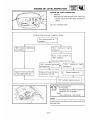
CYLINDEB HEAD" CYF~:N::R: P
1.
~
~
Remove:
•
san
N o T E PI t
nc
pT
IIp~)
Begore removing tha piston pin celt,, cover the
'
with a clean
crankcase
®
®
rag so y o u will not acci
Z. Ro,,,ovo:
• Piston pTn 1~
• Piston ®
• Piston pin bearing ~
GA~ON~
Donot
out_
use a h a m m e r t o d r i v e t h e piston pin
CYUNDER
HEAD INSPECTION
~. Elhxlin~te:
• Carbon deposits
Use a rounded ~crapper
Q'ty
Cvlinder head. Cylinder and piston
removal
1
2
3
4
6
7
8
9
10
Engine
Muffler/Gasket
A i r ~hroud (cylTnder head)
SparkIJlug
Cylinder head/Cylinder head gasket
Cylinder
Piston pin clip
Piston p i n / B e a r i n g
Piston
Pistonring set
CyITnder gasket
•
Rurllark~
@
Cylinder head war~3age
Out of specification >Re8ur'0ce.
Remove the pa~s Enthe order
1/1
1
1
1/1
1
2
Refer to the
tion
"ENGINE REMOVAL" sec-
Warpage
measurement
a n d re s u r f a c e m e n t
• Attach a =traight
•
e d g e ~ a n d a thickness
g a u g e ( ~ on the cylinder head.
M e a s u r e the w a r p a g e limit.
I
1
• If the w a r p a g e is out of specification,
t h e cylinder head.
NOTE:
1
1
Reverse the r e m o v a l procedure f o r in
stallatien.
reface
Rotate the head severaT tTres t o a v o i d r e m o v ing too m u c h moteriol f r o m o n e side.
4-4 . . . . . . . . . . . . . . . . . . . . . . . . . . . . . . . . . . . . .
- -
Q
®
EAS00009
SYMBOLS
GEN
INFO
SPEC
®
®
INSP
ENG
®
~)~
®
CHAS ( ~ ®
CARB
®
ELEC
~=]
TRBL
SHTG
®
@
w.~
•
Symbols (~ to (~) indicate the following.
Serviceable with engine mounted
Filling fluid
Lubricant
Special tool
Tightening torque
Wear limit, clearance
Engine speed
Electrical data
©
®
@
@
@
@
@
@
@
@
®
-n~
@
@
@
®
®
@
i
i
1
®
The following symbols are not relevant to every vehicle.
Symbols (~to (~ are designed as thumb tabs
to indicate the chapter's number and content.
(~ General information
(~ Specifications
(~ Periodic inspection and adjustment
Engine
(~) Carburetor(s)
(~ Chassis
(~ Electrical system
(~ Troubleshooting
@
@
I~lew
Symbols @to @ in the exploded diagrams indicate the types of lubricants and lubrication
points.
(~ Engine oil
@ Gear oil
(~) Molybdenum disulfide oil
(~ Wheel bearing grease
(~ Lithium soap base grease
(~) Molybdenum disulfide grease
Symbols@ to @ in the exploded diagrams
indicate the following.
(~ Apply locking agent (LOCTITE ®)
(~ Replace the part
CHAPTER
GENERAL
SCOOTER INDENTIFICATION
VEHICLE
MODEL
...........................................................................................................
1-1
...........................................................................................
1-1
................................................................................................................................
1-1
IMPORTANT INFORMATION
PREPARATION
............................................................................................................
FOR REMOVAL
REPLACEMENT
GASKETS,
INFORMATION
NUMBER
IDENTIFICATION
CODE
1.
PARTS
OIL SEALS
1-2
.................................................................................................................
1-2
O-RINGS
..........................................................................................
1-2
.........................................................................................................
1-3
........................................................................................................................................
1-3
CHECKING OF CONNECTIONS . . . . . . . . . . . . . . . . . . . . . . . . . . . . . . . . . . . . . . . . . . . . . . . . . . . . . . . . . . . . . . . . . . . . . . . . . . . . . . . . . . . . . . . . . . . . . . . . . . . . . . . .
H O W T O U S E THE CONVERSION TABLE . . . . . . . . . . . . . . . . . . . . . . . . . . . . . . . . . . . . . . . . . . . . . . . . . . . . . . . . . . . . . . . . . . . . . . . . . . . . . . . . . . . . . . .
1-4
CIRCLIPS
AND
CONVERSION
SPECIAL TOOLS
OIL SEALS
TABLE
COTTER
1-2
P I N S ...........................................................................
BEARINGS
AND
DISASSEMBLY
1-2
................................................................
AND
LOCK WASHERS/PLATES
AND
1-5
....................................................................................................................
1-5
................................................................................................................................
1-6
C H A P T E R 2.
SPECIFICATIONS
GENERAL SPECIFICATION
MAINTENANCE
ENGINE
TORQUES
CHASSIS
SPECIFICATION
.....................................................................................................
........................................................................................................................................
TIGHTENING
CHASSIS
TORQUES
...............................................................................................................
........................................................................................................................................
MAINTENANCE
ELECTRICAL
SPECIFICATION
LUBRICATION
2-4
2-4
2-6
2-6
2-7
2-7
2-8
2-8
..................................................................................................... 2-9
...................................................................................................................................
GENERAL TORQUE
CHASSIS
...............................................................................................................
..........................................................................................................................................
MAINTENANCE
ENGINE
.....................................................................................................
..........................................................................................................................................
TIGHTENING
ENGINE
............................................................................................................... 2-1
SPECIFICATION
SPECIFICATIONS
...........................................................................................
POINTS AND LUBRICATION
TYPE
.......................................................................
2-9
2-1 1
2-12
........................................................................................................................................
2-12
......................................................................................................................................
2-13
CABLE ROUTING
.............................................................................................................................
2-14
CHAPTER 3.
PERIODIC I N S P E C T I O N A N D A D J U S T M E N T S
INTRODUCTION
PERIODIC
COVER
................................................................................................................................
MAINTENANCE/LUBRICATION
AND
PANEL
SIDECOVER
LOWER
ENGINE
AND
SEAT
3-1
3-1
................................................................................................................ 3-3
UPPER COVER,
COVER(FRONT
LEG SHIELD
AND
1, 2 A N D
FOOTREST
BOARD
..................... 3-4
REAR) ................................................................................... 3-5
..............................................................................................................................................3 - 6
IDLE SPEED ADJUSTMENT
THROTTLE
CABLE
AUTOLUBE
PUMP
SPARK
PLUG
ENGINE
.......................................................................................................... 3-6
FREE ADJUSTMENT
AIR BLEEDING
INSPECTION
TRANSMISSION
V-BELT
CHASSIS
............................................................................................... 3-8
............................................................................................... 3-10
OIL REPLACEMENT
CLEANING
INSPECTION
..................................................................................... 3-7
........................................................................................................... 3-9
OIL LEVEL INSPECTION
AIR FILTER ELEMENT
........................................................................................ 3-11
.............................................................................................. 3-12
................................................................................................................... 3-14
..........................................................................................................................................3-15
FRONT
BRAKE
REAR BRAKE
LEVER FREE PLAY CHECK ................................................................................ 3-15
LEVER FREE PLAY CHECK ................................................................................... 3-15
BRAKE
PAD INSPECTION
BRAKE
SHOE
BRAKE
FLUID LEVEL INSPECTION
STEERING
........................................................................................................... 3-15
INSPECTION
AIR BLEEDING
INSPECTION
FORK INSPECTION
CHECKING
CENTERSTAND
........................................................................ 3-17
......................................................................................................... 3-22
INSPECTION
ADJUSTMENT
AND
LUBRICATING
ELECTRICAL
SYSTEM)
................................................................................................................... 3-22
ABSORBER
LOCK CABLE
LEVERS
BRAKE
........................................................................................................................3-19
FRONT
CABLE
............................................................................................ 3-16
.......................................................................................................... 3-18
WHEEL
REAR SHOCK
........................................................................................................ 3-16
(HYDRAULIC
ADJUSTMENT
TIRE INSPECTION
SEAT
................................................................
.......................................................................................................................... 3-3
COWLING,
HANDLEBAR
INTERVALS
.................................................................................... 3-22
........................................................................................... 3-22
LUBRICATING
..................................................................................... 3-23
............................................................................................................... 3-23
LUBRICATING
.................................................................................................. 3-23
.....................................................................................................................................3-24
BATTERY
INSPECTION
FUSE INSPECTION
............................................................................................................... 3-24
......................................................................................................................3-29
HEADLIGHT
BEAM
ADJUSTMENT
............................................................................................ 3-30
HEADLIGHT
BULB
REPLACEMENT
............................................................................................ 3-30
TURN
SIGNAL
TAILLIGHT
LICENSE
AND
BULB
LIGHT
TAILLIGHT
REPLACEMENT
BULB
BULB
REPLACEMENT
........................................................... 3-31
.............................................................................................. 3-32
REPLACEMENT
...................................................................................... 3-32
C H A P T E R 4.
ENGINE
E N G I N E O V E R H A U L . . . . . . . . . . . . . . . . . . . . . . . . . . . . . . . . . . . . . . . . . . . . . . . . . . . . . . . . . . . . . . . . . . . . . . . . . . . . . . . . . . . . . . . . . . . . . . . . . . . . . . . . . . . . . . . . . . . . . . . . . 4-1
WlREHARNESS
AND
CABLES
......................................................................................................
4-1
C Y L I N D E R HEAD, C Y L I N D E R A N D P I S T O N . . . . . . . . . . . . . . . . . . . . . . . . . . . . . . . . . . . . . . . . . . . . . . . . . . . . . . . . . . . . . . . . . . . . . . . . . . . . . . . . . . . . 4 - 3
CYLINDER
PISTON
HEAD,
CYLINDER
PIN AND
CYLINDER
HEAD
CYLINDER
AND
AND
PISTON
RINGS
PISTON
PIN AND
PISTON
PIN AND
4-3
4-4
.....................................................................................................
4-4
........................................................................................
4-5
........................................................................................................
4-7
PISTON
PIN BEARING
PISTON
INSTALLATION
CYLINDER
................................................................................
..........................................................................................
INSPECTION
INSPECTION
AND
PISTON
REMOVAL
INSPECTION
PISTON
CYLINDER
PISTON
HEAD
....................................................................................
4-7
................................................................................. 4-8
................................................................................................
4-9
V-BELT, C L U T C H A N D S E C O N D A R Y / P R I M A R Y S H E A V E . . . . . . . . . . . . . . . . . . . . . . . . . . . . . . . . . . . . . . . . . . . . . . . . . . . . . . . . . . . 4-1 1
KICK STARTER
AND
KICK STARTER
.............................................................................................................................
4-12
KICK STARTER
INSTALLATION
4-13
V-BELT,
CLUTCH
SECONDARY
PRIMARY
SECONDARY
V-BELT
AND
PRIMARY
........................................................ 4-14
....................................................................................................
REMOVAL
..............................................................................................
4-15
4-16
4-16
.................................................................................................................
4-17
...................................................................................................................
4-18
................................................................................................
4-19
SECONDARY
SHEAVE
................................................................................................................
4-20
SECONDARY
SHEAVE
INSTALLATION
.....................................................................................
4-21
......................................................................................................................
4-22
PRIMARY
SHEAVE
SHEAVE
................................................................................................................
SHEAVE
INSPECTION
. . . . . . . . . . . . . . . . . . . . . . . . . . . . . . . . . . . . . . . . . . . . . . . . . . . . . . . . . . . . . . . . . . . . . 4-1 1
.................................................................................................
REMOVAL
INSPECTION
COVER(LEFT)
SECONDARY/PRIMARY
SHEAVE
SHEAVE
CLUTCH
CRANKCASE
INSPECTION
SHEAVE
STARTER CLUTCH A N D STARTER M O T O R ................................................................................. 4-24
STARTER
CLUTCH
AND
STARTER
STARTER
CLUTCH
AND
GEARS
C.D.I. MAGNET
MOTOR
.............................................................................. 4-24
INSPECTION
.........................................................................
................................................................................................................................
C.D.I. MAGNETO
.........................................................................................................................
C.D.I. MAGNETO
REMOVAL
C.D.I. MAGNETO
INSTALLATION
.......................................................................................................
..............................................................................................
4-26
4-27
4-27
4-28
4-28
A U T O L U B E P U M P ........................................................................................................................... 4-29
AUTOLUBE
PUMP
.......................................................................................................................
4-29
AUTOLUBE
PUMP
INSTALLATION
4-30
...........................................................................................
T R A N S M I S S I O N .............................................................................................................................. 4-31
TRANSMISSION
..........................................................................................................................
4-31
C R A N K C A S E A N D REED V A L V E . . . . . . . . . . . . . . . . . . . . . . . . . . . . . . . . . . . . . . . . . . . . . . . . . . . . . . . . . . . . . . . . . . . . . . . . . . . . . . . . . . . . . . . . . . . . . . . . . . . . 4 - 3 3
CRANKCASE
AND
REED VALVE
CRANKCASE(RIGHT)
................................................................................................
4-33
................................................................................................
4-35
....................................................................................................
4-35
REMOVAL
CHECKING
THE CRANKCASE
CHECKING
THE
BEARINGS
REED VALVE
INSPECTION
CRANKCASE
(RIGHT)
AND
OIL SEALS
............................................................................ 4-35
.........................................................................................................
INSTALLATION
......................................................................................
4-36
4-36
C R A N K S H A F T .................................................................................................................................. 4-38
CRANKSHAFT
..............................................................................................................................
4-38
CRANKSHAFT
REMOVAL
...........................................................................................................
4-39
CRANKSHAFT
INSPECTION
.......................................................................................................
4-39
CRANKSHAFT
INSTALLATION
...................................................................................................
4-40
CHAPTER 5
CARBURETION
CARBURETION
..................................................................................................................................
CARBURETOR
................................................................................................................................
CABURETOR
DISASSEMBLY
CABURETOR
5-1
5-1
.......................................................................................................
5-2
INSPECTION
...........................................................................................................
5-3
ASSEMBLY
...........................................................................................................
5-5
FUEL LEVEL ADJUSTMENT
.........................................................................................................
5-6
..........................................................................................................
5-7
.............................................................................................................
5-8
CARBURETOR
AUTO
CHOKE
FUEL COCK
INSPECTION
INSPECTION
CHAPTER 6
CHASSIS
F R O N T W H E E L A N D B R A K E D I S C . . . . . . . . . . . . . . . . . . . . . . . . . . . . . . . . . . . . . . . . . . . . . . . . . . . . . . . . . . . . . . . . . . . . . . . . . . . . . . . . . . . . . . . . . . . . . . . . . . . 6-1
FRONT
WHEEL
AND
FRONT
WHEEL
DISASSEMBLY
BRAKE
FRONT
WHEEL
DISASSEMBLY
FRONT
WHEEL
INSPECTION
BRAKE
DISC INSPECTION
D I S C ...............................................................................................
6-1
....................................................................................................
6-2
....................................................................................................
6-3
........................................................................................................
6-3
............................................................................................................
6-4
..........................................................................................................
6-4
FRONT
WHEEL
ASSEMBLY
FRONT
WHEEL
INSTALLATION
WHEEL
STATIC
BALANCE
...................................................................................................
ADJUSTMENT
6-5
.................................................................................. 6-6
F R O N T B R A K E ...................................................................................................................................
6-8
BRAKE
P A D ....................................................................................................................................
6-8
BRAKE
PAD REPLACEMENT
6-9
........................................................................................................
MASTER
CYLINDER
........................................................................................................................
6-12
MASTER
CYLINDER
DISASSEMBLY
.............................................................................................
6-13
..............................................................................................
6-14
................................................................................................
6-14
MASTER
CYLINDER
INSPECTION
MASTER
CYLINDER
ASSEMBLY
MASTER
CYLINDER
INSTALLATION
......................................................................................... 6 - 1 5
CALIPER ........................................................................................................................................... 6 - 1 7
CALIPER DISASSEMBLY
BRAKE
CALIPER
CALIPER
.................................................................................................................
DISASSEMBLY
INSPECTION
................................................................................................
6-18
6-19
................................................................................................................. 6 - 1 9
BRAKE
CALIPER ASSEMBLY
BRAKE
CALIPER
......................................................................................................
INSTALLATION
6-20
............................................................................................... 6 - 2 0
REAR W H E E L A N D REAR BRAKE .................................................................................................. 6-21
REAR WHEEL
...............................................................................................................................
6-21
R E A R B R A K E ................................................................................................................................
6-22
REAR WHEEL
INSPECTION
........................................................................................................
6-23
REAR BRAKE
INSPECTION
.........................................................................................................
6-23
REAR BRAKE
INSTALLATION
HANDLEBAR
....................................................................................................
6-24
....................................................................................................................................
6-25
................................................................................................................................
6-25
HANDLEBAR
HAN DLE BAR INSTALLATIO
STEERING
N .....................................................................................................
........................................................................................................................................
STEERING
....................................................................................................................................
STEERING
REMOVAL
STEERING
INSPCTION
STEERING
INSTALLATION
6-27
6-29
6-29
................................................................................................................. 6 - 3 0
................................................................................................................ 6-31
......................................................................................................... 6-31
F R O N T FORK ................................................................................................................................... 6 - 3 4
FRONT
FORK
FRONT
FORK DISASSEMBLY
...............................................................................................................................
FRONT
FORK REMOVAL
FRONT
FORK DISASSEMBLY
FRONT
FORK INSPECTION
FRONT
FORK ASSEMBLY
FRONT
FORK INSTALLATION
6-34
.....................................................................................................
6-35
.............................................................................................................
6-36
.....................................................................................................
6-36
......................................................................................................... 6-37
........................................................................................................... 6-37
.................................................................................................... 6-39
CHAPTER 7
ELECTRICAL
ELECTRICAL COMPONENTS
............................................................................................................
7-1
........................................................................................................
7-1
........................................................................................................................
7-2
CHECKING SWITCHES ......................................................................................................................
7-4
ELECTRICAL
CIRCUIT
COMPONENTS
DIAGRAM
CHECKING
SWITCH
STEPS
.........................................................................................................................
CONNECTION
AS
SHOWN
IN THIS
MANUAL
.............................................................
S W I T C H P O S I T I O N A N D T E R M I N A L C O N N E C T I O N ......................................................................
C H E C K I N G T H E B L U B S A N D B U L B S O C K E T S ...............................................................................
CHECKING
TYPES
THE
BULBS
OF BULBS
AND
BULB
SOCKETS
...........................................................................
..........................................................................................................................
CHECKING
THE
CONDITION
OF THE
BULBS
CHECKING
THE
CONDITION
OF THE
BULB
..............................................................................
SOCKETS
..............................................................
IGNITION SYSTEM ............................................................................................................................
CIRCUIT
DIAGRAM
........................................................................................................................
TROUBLESHOOTING
CHARGING
CIRCUIT
7-4
7-4
7-5
7-5
7-6
7-6
7-7
7-8
7-9
7-9
..................................................................................................................
7-10
SYSTEM .......................................................................................................................
7-14
DIAGRAM
......................................................................................................................
7-14
TROUBLESHOOTING
..................................................................................................................
7-15
ELECTRIC STARTING SYSTEM ......................................................................................................
7-18
CIRCUIT
DIAGRAM
......................................................................................................................
7-18
TROUBLESHOOTING
..................................................................................................................
7-19
STARTER
MOTOR
.......................................................................................................................
7-22
STARTER
MOTOR
DISASSEMBLY
.............................................................................................
7-23
..........................................................................................................
7-24
LIGHTING SYSTEM .........................................................................................................................
7-26
INSPECTION
CIRCUIT
AND
REPAIR
DIAGRAM
......................................................................................................................
7-26
TROUBLESHOOTING
..................................................................................................................
7-27
........................................................................................................
7-29
SIGNAL SYSTEM .............................................................................................................................
LIGHTING
7-33
CIRCUIT
SYSTEM
DIAGRAM
CHECK
......................................................................................................................
TROUBLESHOOTING
SIGNAL
SYSTEM
..................................................................................................................
CHECK
AUTO CHOKE SYSTEM
7-33
7-34
............................................................................................................
7-36
..................................................................................................................
7-42
DIAGRAM
......................................................................................................................
7-42
TROUBLESHOOTING
..................................................................................................................
7-43
CIRCUIT
CHAPTER 8
TROUBLESHOOTING
STARTING FAILURE/HARD
FUEL SYSTEM
IGNITION
S T A R T I N G . . . . . . . . . . . . . . . . . . . . . . . . . . . . . . . . . . . . . . . . . . . . . . . . . . . . . . . . . . . . . . . . . . . . . . . . . . . . . . . . . . . . . . . . . . . 8-1
...............................................................................................................................
SYSTEM
COMPRESSION
........................................................................................................................
SYSTEM
.............................................................................................................
P O O R IDLE S P E E D P E R F O R M A N C E
POOR
IDLE SPEED
POOR MIDIUM
POOR
PERFORMANCE
AND
HIGH SPEED
FULTY AUTOMATIC(V-BELT
SCOOTER
DOES
OUT
NOT
POOR STANDING
....................................................................... 8-3
PERFORMANCE
................................................................... 8-3
WHILE
ENGINE
IS O P E R A T I N G
.................................................. 8-4
.................................................................................................................
START(LOW
POOR ACCELERATION(POOR
CLIMBING
ABILITY)
HIGH SPEED)
.............................................................................. 8-4
.....................................................................................................................................
P O O R S P E E D .....................................................................................................................................
POOR SPEED
8-4
................................................................. 8-4
O V E R H E A T ........................................................................................................................................
OVERHEAT
8-2
8-3
TYPE) ................................................................................................. 8-4
MOVE
FAILURE
8-2
............................................................................................ 8-3
AND HIGH SPEED PERFORMANCE
MIDIUM
CLUTCH
................................................................................................
8-1
.................................................................................................................................
8-5
8-5
8-5
8-5
I M P R O P E R KICKING .......................................................................................................................... 8-6
SLIPPING
HARD
........................................................................................................................................
KICKING
KICK CRANK
..............................................................................................................................
NOT
RETURNING
...................................................................................................
8-6
8-6
8-6
F A U L T Y BRAKE ................................................................................................................................. 8-7
POOR
BRAKING
MALFUNCTION
E F F E C T ...............................................................................................................
8-7
.............................................................................................................................
8-7
INSTABLE HANDLING
INSTABLE
HANDLING
......................................................................................................................
8-8
..................................................................................................................
8-8
FAULTY SIGNAL AND LIGHTING SYSTEM
HEADLIGHT
BULB
BURNT
.................................................................................... 8-9
D A R K .........................................................................................................................
OUT
........................................................................................................................
FLASHER
DOES
FLASHER
K E E P S O N .....................................................................................................................
FLASHER
BLINKS
SLOWER
FLASHER
BLINKS
QUICKER
HORN
DOES
NOT
B L I N K .........................................................................................................
NOT SOUND
8-9
8-9
8-9
8-9
........................................................................................................
8-10
.......................................................................................................
8-10
.........................................................................................................
8-10
SCOOTER INDENTIFICATION
f
I GEN
EAS00015
GENERAL INFORMATION
SCOOTER IDENTIFICATION
EAS00017
VEHICLE I D E N T I F I C A T I O N N U M B E R
The vehicle identification number (~) is stamped
into the frame.
f
EAS00018
M O D E L CODE
The model code label ~) is affixed to the location s h o w n in the figure. Record the information on this label in the space provided. This
information will be needed to order spare parts.
1-1
IMPORTANT INFORMATION
I GEN
EAS00020
IMPORTANT INFORMATION
P R E P A R A T I O N FOR R E M O V A L A N D D I S A S SEMBLY
1. Before removal and disassembly, remove
all dirt, mud, dust and foreign material.
2. Use o n l y the proper tools and cleaning
equipment.
Refer to "SPECIAL TOOLS".
3. When disassembling, always keep mated
parts together. This includes gears, cylinders, pistons and other parts that have
been
" m a t e d " t h r o u g h normal wear. M a t e d
parts must always be reused or replaced
as an assembly.
4. During disassembly, clean all o f t h e parts
and place them in trays in the order of disassembly. This will speed up a s s e m b l y
and allow for the correct installation of all
parts.
5. Keep all parts a w a y from any source of
fire.
300-008
EAS00021
R E P L A C E M E N T PARTS
Use o n l y genuine Yamaha parts for all replacements. Use oil and grease recom-mended by
Yamaha for all lubrication jobs.
Other brands may be similar in function and
appearance, but inferior in quality.
300-016
EAS00022
G A S K E T S , OIL SEALS A N D O - R I N G S
1. When overhauling the engine, replace all
gaskets, seals and O-rings. All gasket surfaces, oil seal lips and O-rings must be
cleaned.
2. During reassembly, properly oil all mating parts and bearings and lubricate the
oil seal lips w i t h grease.
EAS00023
LOCK W A S H E R S / P L A T E S A N D C O T T E R PINS
After removal, replace all lock washers/plates
~ ) a n d cotter pins. After the bolt or nut has been
tightened to specification, bend the lock tabs
along a flat o f t h e bolt or nut.
1-2
IMPORTANT INFORMATION
I ,NFOI
GEN
I
EAS00024
~\\\\\\\\~1
BEARINGS AND OIL SEALS
Install bearings and oil seals so that the manu
facturer's marks or n u m b e r s are visible. W h e n
installing oil seals, lubricate the oil seal l i p s w i t h
a light coat of lithium soap base grease.
Oil bearings liberally w h e n installing, if appro
priate.
~) Oil seal
CAUTION:
Do not spin the bearing with compressed air
because this will damage the bearing surfaces.
(~ Bearing
EAS00025
CIRCLIPS
Before reassembly, check all circlips carefully
and replace d a m a g e d or distorted circlips,
A l w a y s replace piston pin clips after one use.
W h e n installing a circlip (~), make sure the
s h a r p - e d g e d corner (~) is positioned o p p o s i t e
the t h r u s t ~ that the circlip receives.
(~ Shaft
1-3
IMPORTANT INFORMATION
I GEN
EB801000
CHECKING OF C O N N E C T I O N S
D e a l i n g w i t h stains, rust, m o i s t u r e , etc. on t h e
connector.
1. D i s c o n n e c t :
• Connector
2. D r y each t e r m i n a l w i t h an air b l o w e r .
3.
4.
5.
6.
C o n n e c t and d i s c o n n e c t t h e c o n n e c t o r t w o
or t h r e e .
Pull t h e read to c h e c k t h a t it w i l l not c o m e
off.
If t h e t e r m i n a l c o m e s off, b e n d up t h e pin
( ~ a n d r e i n s e r t t h e t e r m i n a l into t h e c o n Rector.
Connect:
• Connector
NOTE:
The two connectors "click" together.
7.
Check for continuity with a tester.
NOTE:
•
•
•
•
1-4
If t h e r e is no c o n t i n u i t y , c l e a n t h e t e r m i nals.
Be s u r e to p e r f o r m t h e s t e p s 1 to 7 listed
above when checking the wireharness.
For a field r e m e d y , use a c o n t a c t revitalizer
a v a i l a b l e on t h e m a r k e t .
Use t h e t e s t e r on t h e c o n n e c t o r as s h o w n .
H O W TO USE THE C O N V E R S I O N TABLE
I GEN
EB201000
H O W TO USE THE C O N V E R S I O N TABLE
All s p e c i f i c a t i o n data in t h i s m a n u a l are listed in SI and M E T R I C U N I T S .
Use t h i s t a b l e to c o n v e r t M E T R I C u n i t data t o I M P E R I A L u n i t data.
Ex.
METRIC
MULTIPLIER
IMP
** mm
x
0.03937
=
* * in
2 mm
x
0.03937
=
0.083 in
CONVERSION
TABLE
METRIC TO IMP
Known
Multiplier
Result
m.kg
m.kg
cm.kg
cm.kg
7.233
86.794
0.0723
0.8679
ft.lb
in.lb
ft.lb
in.lb
kg
g
2.205
0.03527
Ib
oz
km/h
km
mm
0.6214
0.6214
3.281
1.094
0.3937
0.03937
mph
mi
ft
yd
in
in
Volume/
Capacity
cc(cm 3)
cc(cm 3)
lit(liter)
lit(liter)
0.03527
0.06102
0.8799
0.2199
oz (IMP liq.)
cu.in
qt(IMP liq.)
gal(IMP liq.)
Miscellaneous
kg/mm
kg/cm 2
Centigrade
55.997
14.2234
9/5(°C)+32
Ib/in
psi(Ib/in 2)
Fahrenheit (°F)
Torque
Weight
Distance
m
m
ca
1-5
SPECIAL TOOLS I GEN
EEl02000
SPECIAL TOOLS
T h e f o l l o w i n g s p e c i a l t o o l s are n e c e s s a r y f o r c o m p l e t e and a c c u r a t e t u n e - u p and a s s e m b l y . Use
o n l y t h e a p p r o p r i a t e s p e c i a l t o o l s ; t h i s Will h e l p p r e v e n t d a m a g e c a u s e d b y t h e use o f i n a p p r o p r i ate t o o l s or i m p r o v i s e d t e c h n i q u e s .
W h e n p l a c i n g an o r d e r , r e f e r to t h e list p r o v i d e d b e l o w to a v o i d a n y m i s t a k e s .
Tool No.
YU-01235
Tool name / Function
Illustration
Rotor holding tool
This tool is used to hold the generator rot o r w h e n removing or installing the generator rotor bolt.
YS-28891
Clutch spring holder
This tool is used to disassembly and assembly the secondary pulley.
YU
-90050
-90062
Crankshaft Installation set (~
Adapter (~)
These tools are used to install the crankshaft.
u
Flywheel puller
YU-01189
This tool is used for removing the rotor.
YU-01135-A
Crankcase Separating tool
This tool is used to remove the crankshaft
or separate the crankcase.
YM-33299
Oil seal guide
This tool is used for protecting the oil seal
lip w h e n installing the secondary sliding
sheave.
YU-33975
Steering nut wrench
This tool is used to loosen or tighten the
steering stem ring nut.
YU-01701
Sheave holder
This tool is used to hold the clutch housing w h e n removing or installing the clutch
housing nut.
YU-8036-A
Inductive tachometer
This tool is used to check engine speed.
1-6
0
,.,o1 1
SPECIAL TOOLS I GEN
Tool No.
YU-03112
Tool name / Function
I llustratio n
Pocket tester
This tool is used to c h e c k t h e electrical system.
YM-1409
Oil seal guide
This tool is used to install the left side crankcase oil seal.
YM-1410
Oil seal d r i v e r
This tool is used to install the left side crankcase oil seal.
YM-34487
D y n a m i c spark tester
This i n s t r u m e n t is necessary for checking
the ignition s y s t e m c o m p o n e n t s .
ACC-1100-15-01
Quick Gasket ®
This sealant is used to seal to m a t i n g surfaces (e.g., crankcase m a t i n g sur-faces).
90890-01348
Lockn ut w r e n c h
This tool is used to loosen and t i g h t e n the
c l u t c h c a r r i e r I o c k n u t of t h e s e c o n d a r y
sheave.
YU-33963
-1400
Front fork seal d r i v e r
Weight (~
A d a p t e r Q2~
These tools are used w h e n installing the fork
seal.
T-handle ( ~
YM-01326
Holder
YM-01300-1 ( ~
T h e s e t o o l s are n e e d e d to l o o s e n and
tighten the d a m p e r rod holding bolt.
YM-01312-A
Fuel level gauge
T-handle ( ~ ) / D a m p e r rod holder ( ~
This gauge is used to nleasure the fuel level
in the float chamber.
1-7
®
dJ /
~//
G E N E R A L SPECIFICATION
SPECIFICATION
IsPEcl.-I
GENERAL SPECIFICATION
Model
YW50AP
Model code:
5P J1
Dimensions:
Overall length
Overall w i d t h
Overall height
Seat height
Wheelbase
M i n i m u m ground clearance
M i n i m u m turning radius
1,890 mm(74.4 in)
705 mm(27.8 in)
1,110 mm(43.7 in)
765 mm(30.1 in)
1,275 mm(50.2 in)
120 mm(4.7 in)
2,000 mm(78.7 in)
Basic weight:
With oil and full fuel tank
94 kg(207 Ib)
Engine:
Engine type
Cylinder arrangement
Displacement
Bore x stroke
Compression ratio
Starting system
Lubrication system:
Air cooled 2 strcke, gasoline torque induction
Forward- inclined single cylinder
49cm 3 (2.99 cu.in)
40.0 x 39.2 mm(1.57 x 1.54 in)
7.2:1
Electric and kick starter
Separate lubrication
Oil Type or Grade:
Engine Oil
For Y A M A H A brand:
Yamalube 2 or Air cooled 2-stroke engine oil (ISO
EG-C, EG-D grade)
Transmission Oil
Oil Capacity:
Oil Tank (Engine Oil)
Transmission Oil:
Periodic Oil Change
Total A m o u n t
Yamalube 4 SAE 10W/30 SE or GL gear oil
Air Filter:
Wet type element
Fuel:
Type
Tank Capacity
Regular unleaded gasoline
5.7 L (1.25 Imp.gal, 1.5 US gal)
Carburetor:
Type / Manufacturer
Y14P/1/TEIKEI
1.4 L (1.23 Imp°qt, 1.48 US qt)
0.11 L(0.096 Imp.qt, 0.12 US qt)
0.13 L(0.11 Imp.qt, 0.13 US qt)
2-1
G E N E R A L SPECIFICATION
Model
YW50A
Spark Plug:
Type/Manufacturer
Gap
BPRTHS/NGK
0.6 ~ 0.7 mm(0.02 ~ 0.03 in)
Clutch Type
Dry, Centrifugal automatic
Transmission:
Primary Reduction System
Primary Reduction Ratio
Secondary Reduction System
Secondary Reduction Ratio
Transmission Type
Operation
Helical gear
4.000
Supur gear
3.666
V-belt
Automatic
Chassis:
Frame type
Caster angle
Trail
Steel tube underbone
26.5 °
93mm(3.7 in)
Tire:
Type
Size
front
rear
front
rear
front
rear
Manufacturer
Type
Tubeless
120/90-10
130/90-10
CHENG SHIN
CHENG SHIN
56J
59J
143 kg(315 Ib)
Maximum load*
Cold tire Pressure:
Up to 90 kg
Front
Rear
90 kg load~Maximum load*
Front
Rear
Brake:
Front brake
200kpa(2.0 kg/crn 2, 29 psi)
200kpa(2.0 kg/cm 2, 29 psi)
200kpa(2.0 kg/cm 2, 29 psi)
200kpa(2.0 kg/cm 2, 29 psi)
Single disc brake
Right hand operation
Drum brake
Left hand operation
type
operation
Rear brake
type
operation
Suspension:
Front suspension
Rear suspension
Telescopic fork
Unit swing
Shock absorber:
Front shock absorber
Rear shock absorber
Coil spring/oil damper
Coil spring/oil damper
Wheel travel:
Front wheel travel
Rear wheel travel
65 rnrn(2.56 in)
60 mm(2.36 in)
Electrical:
Ignition system
Generator system
Battery type
Battery capacity
C.D.I
Flywheel Magneto
YTX5L-BS
12V 4AH
2-2
IsPEcl.-I
G E N E R A L SPECIFICATION
Model
Headlight type:
Bulb wattage x quantity:
Headlight
Tail/brake light
Flasher light
Licence plate light
Meter light
High beam indicator light
Oil indicator light
Turn indicator light
YW50A
Bulb
12V 35W/35Wx2
12 5W/21Wx1
V
10Wx4
5Wx 1
3.4Wxl/1.7Wxl
1.7Wx 1
1.7Wx 1
1.7Wx 1
2-3
IsPEcl.-I
MA...E°A.OE SPEO.F.OA-.O° ISPEcl
M A I N T E N A N C E SPECIFICATION
ENGINE
Item
C y l i n d e r head:
Warp l i m i t
Sta nda rd
"~
Limit
0.03 m m
(0.0012 in)
*Lines indicate s t r a i g h t e d g e m e a s u r e m e n t
Cylinder:
Bore size
40.000~40.014mm
(1.5748~1.5754 in)
40.10 m m
(1.5787 in)
0.05 m m
(0.0020 in)
0.03 rnm
(0.0012 in)
0.035~0.040 m m
(0.0014~0.0016 in)
39.958~39.972 m m
(1.5731~1.5737 in)
5 mm(O.2 in)
10.004~10.015 m m
(0.3939~0.3943 in)
9.996~10.000 rnrn
(0.3935~0.3937 in)
0.10 m m
(0.0039 in)
Taper l i m i t
Out of round Ih-nit
Piston:
Piston to c y l i n d e r clearance
Piston size " D "
M e a s u r i n g point " H "
Piston pin bore inside d i a m e t e r
Piston pin outside d i a m e t e r
Piston Ring:
Sectional Sketch (B × T)/'l-ype
Top Ring
1.2 ×
(0.05
1.2 ×
(0.05
2nd Ring
End Gap (Installed):
Top Ring
2nd Ring
I~
Yl
Side Clearance ( Installed):
Top Ring
2nd Ring
2-4
10.045 m m
(0.4 in)
9.975 m m
(0.39 in)
1.6 m m / k e y s t o n e
× 0.06 in)
1.6 r a m / k e y s t o n e
× 0.06 in)
0.15~0.35 m m
(0.005~0.01 in)
0.15~0.35 m m
(0.005~0.01 in)
0.6 mm(O.02 in)
0.03~0.05 m m
(0.0012~0.0020 in)
0.03~0.05 m m
(0.0012~0.0020 in)
0.1 mm(O.O039 in)
0.6 mm(O.02 in)
0.1 mm(O.O039 in)
I
MA..TE°A°OESPEO.F.OAT.O°ISPEcl "
Item
Standard
Crankshaft:
F
Crank Width " A "
Run Out Limit " C "
Connecting Rod Big End Side
Clearance " D "
-
37.90~37.95 mm(1.49~1.49 in)
0.03 mm(0.0012 in)
"--D
.q-
.~p
A
Small End Free Play " F "
A u t o m a t i c centrifugal clutch:
Clutch shoe thickness
Clutch housing inside d i a m e t e r
Clutch shoe spring free length
Clutch - in r e v o l u t i o n
Clutch - stall r e v o l u t i o n
V-belt:
V-belt w i d t h
Kick Starter:
Type
Kick Clip Tension
Carburetor:
I.D. Mark
Main Jet
Needle jet
Jet Needle-clip Position
Main A i r Jet
Cutaway
Pilot Jet
Bypass
Valve Seat Size
Starter Jet
Float Height
Fuel level height
Engine Idling Speed
Limit
0.2~0.5 m m
(0.0029~0.020 in)
0.4~0.8 m m
(0.016~0.031 in)
1.0 mm(0.04 in)
4.0 mm(0.16 in)
105 m m
(4.13 in)
94 mm(3.7 in)
3,300~3,700 r/min
5,500~6,500 r/rain
2.5 mm(0.1 in)
105.5 m m
(4.15 in)
91 mm(3.58 in)
16.6 mm(0.65 in)
14.6 mm(0.57 in)
Ratchet t y p e
1.5~2.5 N (0.15~0.25 kgf)
(0.34~0.56 Ib)
5DA-01
#8O
2.085
3N24-3/5
2.0
3.5
#44
0.8
1.8
#48
15 ~17 ram(0.59 ~ 0.67 in)
3.0~4.0 rnrn(0.12 ~0.16 in)
1,750~1,850 r/rain
(M.J.)
(N J)
(J.N.)
(M.A.J.)
(C.A.)
(P.J.)
(V.S.)
(G.S.)
Reed Valve:
Thickness
Valve Stopper Height
Valve bending l i m i t
0.150~0.154 mm(0.059~0.0060 in)
6.0~6.4 mm(0.24~0.25 in)
0.2 m m (0.0078)
2-5
I
M..°TE°..OE SPEO.F.C.T.O. ISPEcl "" I
TIGHTENING TORQUES
ENGINE
Part to be tightened
Spark plug
Cylinder head and cylinder
Cylinder
Air shroud 1
Air shroud l x 2
Fan
Autolube pump
Reed valve
Air filter
Carburetor cap
Exhaust pipe
Muffler
Exhaust protector
Protector
Crankcase l x 2
T r a n s m i s s i o n case cover
Crankcase cover 1(left)
Bolt(case2)
Crankcase cover2(left)
Drain bolt
Oil plug
Idle gear plate
Kick crank
Starter m o t o r
Clutch housing
Clutch w e i g h t
Magnet base
C.D.I. rotor
Part name
m
Nut
Stud bolt
Screw
Sc rew
Screw
Screw
Bolt
Sc rew
Screw
Screw
Bolt
Bolt
Screw
Bolt
Bolt
Bolt
Screw
Bolt
Bolt
Plug
Screw
Bolt
Bolt
Nut
Nut
Screw
Nut
2-6
Thread
size
M
M
M
M
6.0
M
M
M
M
M
M
M
M
M
M
M
M
M
M
M
M
M
M
M
M
M
M
M
Q'ty
Nm
14
7
7
6
1
6
5
6
6
4
6
8
6
6
6
6
6
6
6
8
14
6
6
6
10
10
6
10
Tightening
torque
120
4 14
4
3
2
3
2
4 11
2
2
2
2 26
3 11
1
6
6
12
1
3
1 18
1
2
1
2
140
130
2
138
m°kg ft°lb
2.0
1.4
10
1.0
0.7
7
0.2
0.7
7
0.4
4
1.1
0.9
9
0.2
2
0.9
9
2.6
1.1
0.9
9
12
1.2
12
1.2
1.2
12
0.7
7
0.7
7
1.8
0.3
3
0.8
8
0.9
9
13
1.3
4.0
3.0
0.8
8
3.8
14
10
7
5.1
1.4
5.1
2.8
8.0
6.5
1.4
6.5
18.2
8.0
6.5
8.4
8.4
8.4
5.1
5.1
13
22
5.8
6.5
9.4
29
22
5.8
27
Remarks
MA.
A.OE SPEO.F.OAT.O. ISPEcl "
CHASSIS
Item
Steering system:
Steering bearing type
No/size of steel balls:
Standard
Ball and race bearing
22 pcs
19 pcs
Upper
Lower
Front suspension:
Front fork travel
Fork spring free length
Fork length (Installed)
Spring rate (K1)
(K2)
Inner tube vend limit
70 rnrn(2.8 in)
236.6 mm(9.31 in)
212.1 mm(8.35 in)
15.68 Nm/mm(1.6 kg/mm,901b/in)
23.5 Nm/mm(2.43 kg/mm,1361b/in)
Rear wheel:
Type
Rim size
Rim material
Rim runout limit
...
...
...
233.6 mm
0.2 mm
(0.008 in)
Rear suspension:
Shock absorber stroke
Shock absorber free length (Installed)
Spring free length (Installed)
Spring rate (K1)
Front wheel:
Type
Rim size
Rim material
Rim runout limit
Limit
55 mm(2.2 in)
281.8 rnrn(11.1 in)
159.8 mm(6.29 in)
71.15 N/mm(7.26 kg/mm,4071b/in)
Cast wheel
MT3.50xl 0
Aluminum
1 mm(0.04 in)
1 ram(0.04 in)
radial
lateral
Cast wheel
MT3.50xl 0
Aluminum
1 mm(0.04 in)
1 mm(0.04 in)
radial
lateral
Front disc brake:
Type
Disc outside diameter x thickness
Single
180x4.0mm
(7.1x0.16 in)
6 ram(0.24 in)
11 mm(0.4 in)
34.93 mm(1.38 in)
DOT #4(or DOT #3)
Pad thickness
Master cylinder inside diameter
Caliper cylinder outside diameter
Brake fluid type
Rear drum brake:
Type
Drum inside diameter
Shoe thickness
Leading, trailing
130 mm(5.12 in)
4 ram(0.16 in)
Brake lever:
Brake lever free play (front at lever side)
Brake lever free play (rear)
Throttle cable free play
2~5 mm(0.08~0.20 in)
10~20 mm(0.39~0.79 in)
3~5 mm(0.12~0.20 in)
2-7
180x3.5 mm
(7.1x0.14in)
0.8 mm(0.03 in)
131 mm(5.16 in)
2 ram(0.08 in)
I
MA.
A.OE SPEO.F.OAT.O. ISPEcl "" I
TIGHTENING TORQUES
CHASSIS
Th read
size
Part to be t i g h t e n e d
M 12
M 10
M
6
M 10
M
8
M 25
M 10
M
8
M
6
M
6
M
5
M
6
M
6
M
5
M
6
M 10
M 14
M
6
M
8
MIO
M
8
M
5
Frame and e n g i n e bracket
E n g i n e bracket, c o m p r e s s i o n rod and e n g i n e
Rear carrier
Rear s h o c k a b s o r b e r and f r a m e
Rear s h o c k a b s o r b e r and e n g i n e
S t e e r i n g ring nut
Handle h o l d e r and s t e e r i n g shaft
Brake hose and m a s t e r c y l i n d e r
Fuel t a n k
Fuel cock
Fuel s e n d e r
Box
Seat lock a s s e m b l y
Plastic parts & c o v e r
Footrest board
Front w h e e l axle and nut
Rear w h e e l axle and n u t
Rear brake cam lever
Front brake caliper and f r o n t fork
Brake disc and h u b
Brake hose and caliper
Brake caliper and bleed s c r e w
2-8
Tightening
torque
Remarks
Nm
m,kg
ft°lb
84
45
13
30
16
22
43
20
10
8.4
4.5
1.3
3.0
1.6
2.2
4.3
2.0
1.0
0.7
0.4
0.7
0.7
0.2
0.7
7.0
12.0
1.0
2.3
2.0
2.3
0.6
61
31
9.4
22
12
16
37
14
7
5.1
2.9
5.1
5.1
1.4
5.1
51
87
7.2
16.6
14.5
16.6
4.3
7
4
7
7
2
7
70
120
10
23
20
23
6
See
"page3-18"
41~
MA.
A.OE SPEO.F.OAT.O. ISPEcl "
ELECTRICAL
Item
Standard
Ignition t i m i n g :
Ignition t i m i n g (B.T.D.C.)
Advanced type
14 °at 5,000 r/min
Fixed
C.D.I.:
Pickup coil resistance/color
limit
...
...
C.D.I. unit m o d e l / m a n u f a c t u r e r
248 ~ 372~ at 20°C (68°F)
(W/R-W/L)
640 ~ 960 ~ at 20°C (68°F)
(B/R-G/W)
5PJ/TIIC
Ignition coil:
M o d e l / m a n ufacturer
M i n i m u m spark gap
P r i m a r y w i n d i n g resistance
S e c o n d a r y w i n d i n g resistance
4WX/TI I C
6 rnrn (0.24 in)
0.32~0.48 ~ at 20°C (68°F)
5.68~8.52k~ at 20°C (68°F)
Spark plug cap:
Type
Resistance
Resin
5 kE2
...
...
Charging System/Type:
Flywheel m a g n e t o
...
Source coil resistance/color
C.D.I. Magneto:
M o d e l / M a n ufacturer
Nominal output
Charging current
5PJ/TIIC
12V 85W/5,000 rpm
0.6A at 3,000r/min
1.2A at 8,000r/min
13~14V at 4,000 rpm
0.48~0.72 ~ (White-Black)
0.4~0.6 ~ (Yellow/Red- Black)
12~15V (3,000~8,000 rpm)
Charging v o l t a g e
Charging Coil Resistance (Color)
Lighting Coil Resistance (Color)
Lighting Voltage
Rectifier:
M o d e l / M a n ufactu rer
Capacity
Withstand voltage
3GF/Taichung
8A
18V
Battery:
Specific g r a v i t y
1.320
Electric starter system:
Type
Starter motor:
M o d e l / m a n ufactu rer/ID n u m b e r
Output
A r m a t u r e coil resistance
Brush overall length
Spring force
...
Constant mesh t y p e
4WX/shulin
0.14 kw
0.0648 ~ 0.0792 E2 at 20°C (68°F)
6.5 m m (0.26 in)
5.49 ~ 8.24 N
(360~540 g) (12.69~19.04 oz)
16.1 m m (0.63 in)
1.05 m m (0.04 in)
Commutator diameter
Mica undercut (depth)
Starter relay:
M o d e l / m a n ufacturer
A m p e r a g e rating
Coil resistance
4WX/Shulin
20A
54~66 E2
2-9
3 m m (0.12 in)
400g
15.1 m m (0.59 in)
I
MA.
A.OE SPEO.F.OAT.O. ISPEcl "
Item
Standard
Horn:
M o d e l / m a n ufacturer
Maximum amperage
4KP/Asian
1.5A
Flasher relay:
Type
Flasher f r e q u e n c y
Capacitor
60~ 120 C y c l e / m i n
Fuel gage:
M o d e l / m a n ufacturer
S e n d e r unit resistance
full
- empty
-
limit
4VP/Sa n Chu
4~10 ~
90~100 ~
Oil level g a u g e :
M o d e l / m a n ufacturer
4VP/Lun Ping
Circuit breaker:
Type
MAIN
Fuse
7 A x l pc .
2-10
...
...
.
.
.
I
OEOERA"TOROOESPEC,F,CAT,ONS ISPEcl "
GENERAL TORQUE
SPECIFICATIONS
A
(Nut)
This chart specifies torque for standard fasteners w i t h standard I.S.O. pitch threads. Torque
specifications for special c o m p o n e n t s or assemblies are included in the applicable sections
of this book. To avoid warpage, tighten multifastener assemblies in a crisscross fashion, in
progressive stages, until full torque is reached.
Unless otherwise specified, t o r q u e specifications call for clean, dry threads. C o m p o n e n t s
should be at room temperature.
F-A
Am
A: Distance across flats
B: Outside thread diameter
2-11
B
(Bolt)
I
General t o r q u e
specifications
m°kg
ft°lb
Nm
10 m m
6 mm
6
0.6
4.3
12 m m
8 mm
15
1.5
11
14 m m
10 m m
30
3.0
22
17 m m
12 m m
55
5.5
40
19 m m
14 m m
85
8.5
61
22 m m
16 m m
130
13.0
94
LUB..OAT.O° PO.°TS A.O LUB..OAT.O° T'.PE ISPEcl ""
L U B R I C A T I O N POINTS A N D L U B R I C A T I O N TYPE
ENGINE
Lubrication Point
Lublicant Type
Oil seal lips
O-rings
Bearings
--~11~
Piston surface
--411~
Piston pin
--411~
Cyl i n d e r
--~11~
Transmission case (bearing)
---411~
Autolube pump
Starter wheel gear
Idle gear plate
--~11~
Secondary drive gear
----II1~
Kickstarter pinion gear
Drive axle
---~11~
Pump drive gear
Main axle
--'qG
Main axle (bearing)
---~11~
2-12
I
• OB"'OAT'O" PO'°TS A"O'OB"'OAT'O° T PE ISPEcl "
CHASSIS
Lubrication Point
Lubricant Type
Oil seal lips
O-rings
Bearings
Speedometer drive gear
Front brake camshaft
Front brake cable
Throttle cable
Tube guide (throttle grip) inner surface
Upper steering stem ring nut
Upper bearing outer race
Lower bearing outer race
Rear brake camshaft
Centersta nd
2-13
I
CAB'E.OOT,.O ISPEcl "
CABLE R O U T I N G
(~ Horn
(~ Rectifier regulator
(~ Main switch
(~ Headlight leads
(~) Speedometer cable
(~ Ignition coil
(~ Throttle cable 1
(~ Throttle cable 3
(~ Battery negative(-)
@ Wire brake
(~) Fuel sender lead
(~) Seat lock cable
(~) Oil tank hose
@
C.D.I.
unit
(~) Wire harness
[ ] Pass the speedometer cable
through the right hole of front
fender, then t h r o u g h the
guide.
[ ] Pass the wire harness through
the inside of ignition coil.
[ ] Secure the ground lead and
the ignition coil base to the
ignition coil stay.
[ ] Pass the wire harness through
the inside of oil tank.
[ ] Pass the seat cable through
the inside of frame.
[ ] Align the clip with the white
2-14
brand.
[ ] Clamp the wire harness.
[ ] Insert the seat cable through
the frame tube.
[ ] C l a m p w i r e h a r n e s s , rear
brake cable throttle cable 1,3.
[ ] Position the cylinder between
the s u p p o r t e r and main
switch.
I
OAB'E.OOT,°O
(~
(~)
(~
(~
(~
(~
(~
(~
(~
@
@
Brake cable
Speedometer cable
Fuel tank overflow hose
Brake cable holder
Brake hose
Brake hose holder
License bracket
Flasher relay
Fuel tank breather hose
Fuel hose
Breather hose
[ ] Pass the brake hose through the holder.
[ ] Insert the fuel overflowhose bottom.
[ ] Pass the fuel overflowhose through the rear
fender hole.
[ ] Pass the fuel o v e r f l o w h o s e t h r o u g h the
holder.
[ ] Hold the fuel overflowhose with a clamp.
[ ] Pass the brake cable through the holder.
2-15
ISPEcl
CAB'E.OOT,°O IS"Eel "
(~
(~)
(~
(~
(~
(~
(~
(~
(~
@
[ ] Pass the brake hose through the holder.
Brake
hose
Front fender
Front fork assembly
Nut
Plate washer
Brake
holder
hose
Flange bolt
Bolt
Brake
holder
hose
Flange
bolt
Q
./
/
t
/
/
/
/
/
/(~
f f
2-16
I
C,B'E.OOT,°O IS"Eel "
and autolube hose on to carburetor throttle cable.
[ ] Pass the battery leads over frame
member.
[ ] Put fuse box on to footrest board
holder.
[ ] Pass throttle cable1,3 wireharness,
autolube pump cable, brake cable
through the outside of battery box.
@ Battery(+)lead
(~ Ignition coil
[ ] Pass battery leads through
(~) Spark plug lead
the slot of footrestboard.
(~ Starter relay leads
[ ] Cover them after securing
(~ Auto choke leads
starter relay leads.
(~ Starter relay
[ ] Pass the seat lock cable
(~ Bind
through the hole of bracket.
(~ C.D.I. unit
[ ] Pass the fuel tank breath
(~ Autolube hose
hose over seat lock cable.
(~ Seat lock cable
[ ] Clamp carburetor vacuum
@ Bracket
hose, fuel hose and fuel
@ Fuel tank breather hose
cock vacuum hose.
@ Bind 2
[]Clamp
a u t o c h o k e leads
(~ Battery(-)lead
B
~i~
r
iJ
"
~~,~ .........
D
~ ~ q ~ - ~ l
~,
..q-.~,J
I
I
*~/'~
~ .......
@~.
2-17
I
•
~.,~J ',~
I
CAB'E ROOT,OO ISPEcl "
(~ Handlebar switch(right)
(~) Speedometer
(~ Wire brake
(~ Handlebar switch(left)
(~ Wire harness
(~ Brake hose
(~ Speedometer cable
(~ Throttle cable1
(~ Throttle cable 3
@ Front flasher leads
[ ] Pass brake cable through the slot of bracket.
[ ] Avoid clamping front flasher leads when installing handlebar covers.
[ ] P a s s throttle cable1,3 t h r o u g h between
handlebar and wireharness.
[ ] Hang the wireharness bind on to the bracket.
f
I
"
:'7. . . . . . . . . . . . . . .
[j}j~
~I
....
!
F
i
i
~ L
~', JI . . . . . .
#
B
]3
C
2-18
I
INTRODUCTION/
PERIODICIVIAINTENANCE/LUBLICATION INTERVALS
I INSP
EB300000
PERIODIC INSPECTIONS AND ADJUSTMENTS
INTRODUCTION
T h i s c h a p t e r i n c l u d e s all i n f o r m a t i o n
ments. These preventive
operation
necessary'to perform
maintenance
procedures,
recommended
if f o l l o w e d ,
inspections and adjust-
will ensure more reliable vehicle
a n d a l o n g e r s e r v i c e life. T h e n e e d f o r costly" o v e r h a u l w o r k w i l l be g r e a t l y " r e d u c e d . T h i s
information
a p p l i e s t o v e h i c l e s a l r e a d y ' in s e r v i c e as w e l l as t o n e w v e h i c l e s t h a t a r e b e i n g p r e -
pared for sale. All service technicians
s h o u l d be f a m i l i a r w i t h t h i s e n t i r e c h a p t e r .
YP301000
PERIODIC MAINTENANCE/LUBRICATION INTERVALS
BREAK-IN
NO.
1
ITEM
*
3
4
*
ROUTINE
TYPE
Fuel line
• Check fuel hoses and v a c u u m hose
f o r cracks or d a m a g e .
• Replace if necessary.
-
Spark p l u g
• Check c o n d i t i o n .
Refer to SPARK
• Clean, regap or replace if neces- PLUGINSPECTION
sa ry.
Air filter element
• Clean or replace if necessary,
Front brake
• Check o p e r a t i o n , f l u i d e level and Brakefluid DOT4
v e h i c l e f o r f l u i d leakage.
Ior DOT3)
•
•
6
7
•
•
•
* Tires
0
-
O
O
0
O
worn to the limit.
O
O
O
worn to the limit.
-
C h e c k t r e a d d e p t h and f o r d a m a g e .
Replace if necesssary.
Check air pressure.
Correct if necessary.
Wheel bearings
• Check Bearing for looseness or
damage.
• Replace if necessary.
9
*
Steering
ings
• Check b e a r i n g play and steering for
roughness.
Chassis fasteners
0
and for
~
1C *
O
0
Whenever
8
bear-
0
0
Whenever
Replace brake shoes.
• Check balance, runout
damage.
• Replace if necessary.
Wheels
*
6,000 km
(4,000 mi)
or
12months
(wh]chever
c o m e s fi rst
ginooil
Replace brake pads.
• Check o p e r a t i o n .
• A d j u s t brake lever free play.
* Rear brake
5
s. . . . . . .
INITIAL
1,000 km
(600 mi)
EVERY
3,000 km
(2,000 mi)
or
6 months
(whichever
co mes first
-
O
-
-
• M a k e sure t h a t all nuts, bolts and
s c r e w s are p r o p e r l y t i g h t e n e d .
-
O
O
O
O
0
• L u b r i c a t e w i t h l i t h i u m soap base
greese,
3-1
O
0
O
0
Every 12,000 km(8,000 mi)or 24
months(whichever
occurs first).
0
0
PERIODICINSPECTION AND
ADJUSTMENTSI INSPDI
EVERY
BREAK-IN
NO.
ITEM
TYPE
ROUTINE
11
Centerstand
• Check operation.
• Lubricate with lithium soap base
greese (all purpose grease).
12"
Front fork
- Check operation and for oil leakage.
13"
Rear s h o c k absorberassembly
- C h e c k o p e r a t i o n and shock absorber for oil leakage.
- Replace shock absorber assembly
if necessary.
14
*Carburetor
15"
A u t o l u b e pump
• Check operation.
- Correct if necessary.
• Bleed if necessary.
16"
Final t r a n s m i s sion oil
- C h e c k o i l level and vehicle for oil
leakage.
• Check engine idling speed.
• Adjust if necessary.
•
17 *
V-belt
Replace.
o Replace.
Sarne as engine
INITIAL
1,000 km
(600 mi)
oil
I
3,000 km
(2,000 mi)
or
6 months
(whichever
comes first)
O
6,000 km
(4,000 mi)
or
12months
(wh ichever
comes fi rst
O
-
O
O
-
O
O
-
O
O
O
-
O
@
O
-
O
O
O
Yarnalubel
300W
SE 4orSAEGL
gear oil
O
E v e r y 12,000 k m ( 8 , 0 0 0
mi)or 24 mont hs(whichever
Occurs first).
Every 9,000 kin(6,000 mi)
I t e m s m a r k e d w i t h an a s t e r i s k (*) r e q u i r e s p e c i a l t o o l s , d a t a a n d t e c h n i c a l skills f o r s e r v i c i n g . T a k e
t h e s c o o t e r to a Y a m a h a d e a l e r .
NOTE:
• T h e air f i l t e r n e e d s m o r e f r e q u e n t s e r v i c e if y o u are r i d i n g in u n u s u a l l y w e t or d u s t y areas.
• Brake f l u i d r e p l a c e m e n t :
1. R e p l a c e t h e b r a k e f l u i d a f t e r d i s a s s e m b l i n g t h e m a s t e r c y l i n d e r or c a l i p e r c y l i n d e r . C h e c k t h e
b r a k e f l u i d level a n d a d d f l u i d as r e q u i r e d .
2. R e p l a c e t h e m a s t e r c y l i n d e r a n d c a l i p e r c y l i n d e r oil seals e v e r y t w o years.
3. R e p l a c e t h e b r a k e h o s e s e v e r y f o u r y e a r s , o r if c r a c k e d o r d a m a g e d .
NOTE:
F r o m 6,000 mi (9,000 k m ) - o r 18 m o n t h s , r e p e a t t h e m a i n t e n a n c e i n t e r v a l s s t a r t i n g 2,000 mi (3,000
mi) o r 6 m o n t h s .
3-2
COVER AND PANEL
COVER AND PANEL
I
INSP
SIDECOVER A N D SEAT
'
i
~,~/~
~ m . k g ,
9.4ft.lb)
8
y---//
j
j
@
Order
.
J o b name/Part n a m e
Q'ty
Remarks
Remove the parts in order.
NOTF"
Sidecover and seat removal
Battery box cover
Insert the (-) s c r e w d r i v e r into the slot of
battery cover and pickup then remove.
.
3.
4.
5.
6.
7.
8.
Seat
Seat hange
Rear carrier
Rear cover
Left side cover
Right side cover
Center cover
Reverse the removal procedure for installation.
3-3
I
COVER AND PANEL
INSP
LOWER COWLING, UPPER COVER, LEG SHIELD 1, 2 A N D FOOTREST BOARD
4
5
[~1 7Nm(0.7m.kg, 5.1ft.lb)
6
..
o
~
""
~
I
/
//
Order
.
2.
3.
4.
5.
6.
Job n a m e / p a r t name
L o w e r c o w l i n g , u p p e r cover, leg
shield 1,2 and f o o t r e s t board removal
Lower c o w l i n g
Upper cover
Leg shield 1
Main switch c o v e r / l e g shield 2
Battery
Footrest board
Q'ty
Remarks
Remove the parts in order.
1
1
1
1/1
1
1
Reverse the removal procedure for installation.
3-4
COVER AND PANEL
I
INSP
H A N D L E B A R C O V E R ( F R O N T A N D REAR)
1
Order
1.
2.
3.
4.
Job name/Part name
H a n d l e b a r c o v e r ( F r o n t and Rear) removal.
Mirrors
Front h a n d l e b a r c o v e r
Rear h a n d l e b a r c o v e r
Flasher light(Left/Right)
Q'ty
Remarks
R e m o v e t h e part in order.
2
1
1
1/1
Reverse the r e m o v a l p r o c e d u r e for installation.
3-5
ENGINE
IDLE SPEED ADJUSTMENT
I INSP
ENGINE
IDLE SPEED A D J U S T M E N T
1. Remove
• Battery box cover (~
2. Tighten:
• Pilot air screw (~)
Turn the pilot air screw in until lightly
seated.
3. Loosen:
• Pilot air screw
Back it out from its lightly seated position.
I
Pilot air screw turn out:
load 1-1/4
\
I
2. Start the engine and let it warm up.
r!~VAVL,W--']~ I [¢-!
I ~
Before starting t h e engine, be sure to use t h e
c e n t e r s t a n d for safety.
. Attach:
• Inductive tachometer (~
To the spark plug lead
I<~1
4.
Inductive tachometer:
YU-8036-A
Check:
• Engine idle speed
Out of specification-->Adjust.
I-~1
Engine idle speed
1,750~1,850 r/min
5. Adjust:
• Engine idle speed
Adjustment steps.
• Turn the throttle stop screw(~ in or out until
specified idle speed is obtained.
I
3-6
Turn
Turn
i:u
t speed Idle
becomes
speed
Idle becomes
higher.
lower.
THROTTLE CABLE FREE A D J U S T M E N T
I INSP
T H R O T T L E CABLE FREE A D J U S T M E N T
1.
Check:
• Throttle cable free play (~
Out of specification-->Adjust.
ree3 o~ mm(0.12
5
~ 0.20 in)
I
Throttle cable free play a d j u s t m e n t steps;
NOTE:
Before adjusting the throttle cable free play, the
engine idle speed should be adjusted.
• Remove the adjuster cover (~
• Loosen the Iocknut @~)on the throttle cable.
• Turn the adjuster (~ in or out until the specified free play is obtained.
I T u r n i n g in--~Free play is increased.
T u r n i n g out->Free play is decreased.
• Tighten the Iocknuts.
• Install the adjuster cover
After adjusting the throttle cable free play, start
the engine and turn the h a n d l e b a r to the right
and to the left to ensure that this does not cause
the engine idling speed to change.
3-7
I
I INSP
A U T O L U B E P U M P AIR BLEEDING
A U T O L U B E P U M P AIR BLEEDING
1. Remove
• Lower cowling
• A i r shroud 1 (~
2. Air bleeding:
• Pump case and / or oil hose.
*
*
*
*
*
*
*
*
*
*
*
*
*
*
*
*
*
*
*
*
~
~
~
~
~
Air bleeding steps:
• Place a rag under the autolube p u m p t o catch
the oil.
• Remove the bleed screw (~.
• Keepthe oil running out until air bubbles disappear.
• When air bubbles are expelled completely,
tighten the bleed screw.
NOTE:
Check the bleed screw gasket. If damaged, replace w i t h a new one.
Place a oil pan under the autolube p u m p to
catch oil.
3.
Air bleeding:
• Pump d i s t r i b u t o r and/or delivery hose
Air bleeding steps:
• Start the engine.
• Run the engine for 2-3 minutes at 2000 r / m i n .
This will c o m p l e t e l y r e m o v e autolube p u m p
system of air.
3-8
~
~
~
~
SPARK PLUG INSPECTION INSP
I
SPARK PLUG I N S P E C T I O N
1.
2.
I
Remove:
• Battery box cover
Inspect:
• Spark plug type
I nco rrect-->Replace.
Standard spark plug:
BPR7HS/NGK
3.
4.
5.
Inspect:
• Electrode (~
Wea r/Da m ag e-->Re place.
• Insulator (~)
A b n o r m a l color->Replace.
Normal color is a medium-to-light tan
color.
Clean the spark plug w i t h a spark plug
cleaner or wire brush.
Measure:
• Plug gap (~
Use a wire gauge or feeler gauge.
Out of specification-->Regap.
I l'0ar'0u00ao
0.6 ~ 0.7 m m (0.02 ~ 0.03 in)
6.
7.
3-9
I
I
Tighten:
• Spark plug
I~4~i20Nm(2"0m'kg'14ft'lb) I
Install:
• Battery box cover.
I
E N G I N E OIL LEVEL I N S P E C T I O N
INSP
E N G I N E OIL LEVEL I N S P E C T I O N
1. Inspect:
• Engine oil level Oil level Iow--~Add sufficient oil by the f o l l o w i n g inspection
steps.
(~ "OIL" indicator light
Engine oil level visual inspection steps:
Turn main switch to " * "
position.
t
|
"OIL" indicator
comes on.
"OIL" indicator light does I
not comes on.
I
light
Turn main switch
" O N " position.
t
/
"OIL" indicator light does I _
not come on.
C
Inspect f a u l t y electrical
circuit, light bulbs etc.
to
Engine oil level and electrical circuit are OK.
"OIL" indicator
comes on.
1
light
S u p p l y engine oil.
"OIL" indicator light comes on.
©1
Recommended oil:
For Yamaha:
Yamalube 2 or 2-stroke engine oil
(ISO EG-C, EG-D grade)
Total:
1.4L(1.23 Imp.qt, 1.48 US.qt)
NOTE:
Install the oil tank filler cap (~ and push it fully
into the filler.
3-10
T R A N S M I S S I O N OIL R E P L A C E M E N T
TRANSMISSION
I INSP
OIL R E P L A C E M E N T
1.
Warm up the engine for several minutes,
then stop the engine.
2. Place a container under the drain hole.
3. Remove:
• Oil filler plug (~
• Drain bolt (with gasket) ~)
NOTE:
Drain the t r a n s m i s s i o n oil completely.
While draining, slightly tilt the scooter to
the right and to the left.
4.
Inspect:
• Gasket (drain bolt) (~
• O-ring (oil filler plug) (~
Damage--~Replace.
5.
6.
Install:
Drain bolt
H 18 .m
Fill:
• Transmission case
m,g. 13.,,)1
©1
Recommended oil:
Yamalube 4 SAE 10W 30SE or GL gear
oil
Oil capacity:
Total a m o u n t
0.13 L (0.11 Imp.qt, 0.13 US.qt)
Periodic oil change
0.11 L(0.096 Imp.qt, 0.12 US qt)
CAUTION:
•
•
A l w a y s use t h e s a m e t y p e of oil; m i x i n g
oils m a y r e s u l t in a h a r m f u l c h e m i c a l reaction a n d lead t o p o o r p e r f o r m a n c e .
Do n o t a l l o w f o r e i g n m a t e r i a l t o e n t e r s
t h e t r a n s m i s s i o n case.
7.
Install:
• Oil filler plug (with O-ring)
8. Inspect:
• Oil leaks
• Oil level
NOTE:
Wipe off any oil spilt on the t r a n s m i s s i o n , tire
or wheel.
3-11
AIR FILTER E L E M E N T C L E A N I N G
I INSP
AIR FILTER E L E M E N T C L E A N I N G
1. Remove:
• Battery b o x c o v e r
2. Remove:
• Caburetor jont clamp ~)
3.
Remove:
• Screw
• A i r filter ( ~
4.
Remove:
• A i r filter case (~)
• A i r filter e l e m e n t
CAUTION:
N e v e r o p e r a t e t h e e n g i n e w i t h t h e air f i l t e r ele m e n t r e m o v e d . T h i s w i l l a l l o w u n f i l t e r e d air
t o enter, c a u s i n g r a p i d w e a r and p o s s i b l e engine damage. Additionally, operation without
t h e c l e a n e r e l e m e n t w i l l affect c a r b u r e t o r jett i n g w i t h s u b s e q u e n t p o o r p e r f o r m a n c e and
possible engine overheating.
Be careful n o t t o h a v e rags or t h e like b l o c k i n g
t h e i n t a k e area of t h e air filter.
5.
6.
Inspect:
• Element (~
Da mage-->Replace.
Clean:
• A i r filter e l e m e n t
A i r filter e l e m e n t c l e a n i n g steps:
• W a s h the e l e m e n t g e n t l y , but t h o r o u g h l y in
solvent.
3-12
AIR FILTER E L E M E N T C L E A N I N G
AWARNING
I
INSP
N e v e r use l o w flash p o i n t s o l v e n t s such as
gasoline t o clean t h e e l e m e n t . Such s o l v e n t
m a y lead to a fire or explosion.
• S q u e e z e t h e e x c e s s s o l v e n t o u t of t h e elem e n t a n d let dry.
CAUTION:
Do not t w i s t t h e e l e m e n t w h e n s q u e e z i n g t h e
element.
• A p p l y t h e f o a m -air f i l t e r oil or e n g i n e o i l .
• S q u e e z e o u t t h e e x c e s s oil.
NOTE:
T h e e l e m e n t s h o u l d be w e t b u t n o t d r i p p i n g .
7.
Install:
• Air filter
• Battery box cover
3-13
V-BELT I N S P E C T I O N
I INSP
V-BELT INSPECTION
1. Remove:
• Kick crank ( ~
• Screws (~
• Crankcase c o v e r 2(left) (~)
• S c r e w s ( A i r c l e a n e r and left crankcase
cover (~
• Crankcase c o v e r 1(left) ( ~
.
Inspect
• V-belt ( ~
Cracks/Wea r/Da mage-->Replace.
Oil or grease a d h e r e to t h e
V-belt-->Check the p r i m a r y and s e c o n d ary sheaves.
Refer to "ENGINE OVERHAUL -INSPECTION A N D REPAIR" section in the CHAPTER 4.
.
Measure:
• V-belt w i d t h ( ~
Out of specification-->Replace.
Refer to " E N G I N E O V E R H A U L " section
in the CHAPTER 4.
~
V-belt w i d t h "
16.6 m m (0.65 in)
< L i m i t > 14.6 m m (0.57 in)
NOTE:
M e a s u r e the V-belt w i d t h on several points.
4.
Install:
• Crankcase c o v e r 1 (left)
• A i r cleaner
I~%l
[ ~ l 9N
• Crankcase c o v e r 2 (left)
3-14
• Kick crank
12Nm(1.2m.kg,ft.lb) I
m(0.9m.kg,
6.5 ft.lb) I
8
F"O"T
B"A"E'EVE" F"EE P'AY C"EC"'"EA" B"A"E I,.Sp I
LEVER FREE PLAY CHECK/BRAKE PAD INSPECTION A D J
I
CHASSIS
F R O N T BRAKE LEVER FREE PLAY CHECK
1.
Check:
• Front brake lever free play
I ~ 1
2~5 mm(0.08~0.20 in)
I
xkWARNING
A soft or s p o n g y feeling in the brake lever can
indicate the presence of air in the brake system. This air must be removed by bleeding the
brake system before the motorcycle is operated. Air in the system will cause greatly diminished braking capability and can result in
loss of control and an accident. Inspect and
bleed the system if necessary.
REAR BRAKE LEVER FREE PLAY CHECK
1.
Check:
• Rear brake lever free play (~
Out of specification-->Adjust.
I~110~20 mm,o3~0 79,n,
Rear brake lever free play adjustment steps:
• Turn the adjuster (~ in or out until the correct free play is obtained.
<
X
I
o
to
BRAKE PAD I N S P E C T I O N
j
3-15
1. Activate the brake lever.
2. Inspect:
• Brake pad
Wear i n d i c a t o r (~ nearly c o n t a c t i n g
brake disc-->Replace brake pads as a set.
Refer to the "BRAKE PAD REPLACEMENT" section in the CHAPTER 6.
(~ Brake disc
(~ Brake pads
B"AKES"OE'"SPECT'O°'I'"SP I
BRAKE FLUID LEVEL INSPECTION
\
BRAKE SHOE I N S P E C T I O N
1.
2.
Activate the brake lever.
Inspect:
• W e a r indicator (~
Indicator at w e a r limit line (~)-->Replace
brake shoes.
BRAKE FLUID LEVEL I N S P E C T I O N
NOTE:
Position the scooter straight up w h e n inspecting the fluid level.
G-L
m
.
Ii~l
Inspect:
• Fluid level is under " L O W E R " level line
(~-->Fill to proper level.
R e c o m m e n d e d fluid:
DOT#4(or DOT#3)
CAUTION:
The fluid m a y corrode p a i n t e d surfaces or plastic parts. A l w a y s clean up spilled fluid i m m e diately.
~!~LvAv/±1-']~ I [¢!
I~
e U s e o n l y t h e d e s i g n a t e d q u a l i t y fluid. Otherw i s e ,the r u b b e r s e a l s m a y d e t e r i o r a t e causing leakage and p o o r brake p e r f o r m a n c e .
eRefill w i t h t h e s a m e t y p e of fluid. M i x i n g fluids m a y result in a harmful chemical reaction
leading to p o o r brake p e r f o r m a n c e .
eBe careful t h a t w a t e r does n o t enter t h e master cylinder w h e n refilling. W a t e r w i l l significantly l o w e r t h e boiling p o i n t of t h e fluid and
m a y result in v a p o r lock.
3-16
I
AIR BLEEDING
(HYDRAULIC
BRAKE
SYSTEIVI)I INSP
AIR BLEEDING (HYDRAULIC BRAKE SYSTEM)
1. Bleed:
• Brake f l u i d
Air bleeding steps:
a. A d d p r o p e r brake f l u i d to the reservoir.
b. Install the d i a p h r a g m . Be careful not to
spill a n y f l u i d or a l l o w t h e r e s e r v o i r to
overflow.
c. C o n n e c t t h e clear plastic tu be ( ~ t i g h t l y to
the caliper bleed screw.
d. Place the o t h e r end o f t h e t u b e into a container.
e. S l o w l y a p p l y t h e brake lever several times.
f. Pull the lever in. Hold the lever in position.
g. Loosen the bleed s c r e w and a l l o w the lever to t r a v e l t o w a r d s its limit.
h. T i g h t e n the bleed s c r e w w h e n the l i m i t
has been reached, t h e n release the lever.
i. Repeat steps ( e ) t o (h) until the air b u b b l e s
have been r e m o v e d f r o m t h e s y s t e m .
j. A d d brake f l u i d to p r o p e r level.
1
~!~LvAv/±1-'t ~ I [¢-!
I ~
Check the operation of the brake after bleeding the brake system.
3-17
I INSP
STEERING ADJUSTMENT
STEERING ADJUSTMENT
1. Check:
• Steering assembly bearings
Gap the bottom of the forks and gently
rock the fork assembly back and forth.
Loosen-->Adjust.
*
*
*
*
*
*
*
*
*
*
*
*
*
*
*
*
*
*
*
*
~
~
~
~
~
~
A d j u s t m e n t steps:
• Remove u p p e r cover, l o w e r c o w l i n g , leg
shield 1,2. refer to "COVER AND PANEL" section.
• Remove all ringnuts using ringnut wrench.
!
::~1 Ring nut wrench:
YU-33975
I
• Tighten the ring nut 3 (~ using nut wrench.
[~122 Nm(2.2 m.kg, 16 f-t.lb) I
NOTE:
Set the torque wrench to the ring nut w r e n c h
so that they form a right angle.
• Loosen the ring nut 3 (~ 1/4 turn.
• Install rubber ring (~) and ring nut 2 (~, then
tighten the ring nut 2 until it contacts w i t h
rubber ring.
CAUTION:
Aligning the slot of ring nut 2 w i t h the slot of
ring nut 3. If not, slightly t i g h t e n ring nut 2 until the slots a l i g n m e n t .
• Install special w a s h e r (~
NOTE:
Insert the projections of special w a s h e r into the
slots of ring nut 3, 2
• Install ring nut 1 ( ~ r~166Nm(6.6 m.kg, 478~.b> I
• Move the handlebar up and d o w n , and/or
back and forth. If handlebar play is excess,
remove the front fork assembly and check
the balls/ball races. Refer to chapter 6.
3-18
~
~
~
TIRE I N S P E C T I O N
FRONT
Manufacturec
CHENG SHIN
TIRE I N S P E C T I O N
Size
120/90-10
WARNING
Type
56J
• The tire pressure should only be checked and
r e g u l a t e d w h e n t h e tire t e m p e r a t u r e equals
t h e a m b i e n t air t e m p e r a t u r e ,
• T h e tire pressure m u s t be adjusted according to t h e total w e i g h t (including cargo, rider
passenger and accessories) and t h e anticip a t e d riding speed,
• O p e r a t i o n of an o v e r l o a d e d scooter could
cause tire d a m a g e , an accident or an injury,
N E V E R O V E R L O A D THE SCOOTER,
REAR
Manufacturec
CHENG SHIN
I INSP
Size
130/90-10
Type
59J
Basic
weight
( w i t h oil and a 9 4 k g ( 2 0 7 1 b )
full uel tank)
M a x i m u m load* 1 4 3 k g ( 3 1 5 1 b )
Front
Rear
Cold t i r e pres- 200 kpa
200 kpa
(2.0 kgf/cm 2, (2.0 kgf/cm<
sure
29 psi)
29 psi)
* Total of cargo, rider, passenger and accessories.
•WARNING
It is d a n g e r o u s to ride w i t h a w o r n - o u t tire.
When the tire tread reaches the w e a r limit, replace the tire immediately.
.
>
Inspect:
• Tire surfaces
Wea r/Da m age-->Re place.
M i n i m u m tire tread depth (~
(front and rear):
1.6 mm (0.06 in)
®
(~ Tread depth
(~) Side wall
(~) Wear indicator
3-19
CHECKING THE
TmESl INSP I I
•WARNING
a__l
• Do not use a tubeless tire on a w h e e l designed only for t u b e tires t o avoid tire failure and personal injury f r o m sudden deflation.
• When using t u b e tires, be sure t o install t h e
correct tube.
• A l w a y s replace a n e w t u b e tire and a n e w
t u b e as a set.
• To avoid pinching the tube, make sure t h e
w h e e l rim band and t u b e are centered in t h e
w h e e l groove.
• Patching a p u n c t u r e d t u b e is n o t r e c o m mended. If it is a b s o l u t e l y necessary t o do
so, use great care and replace t h e t u b e as
soon as possible w i t h a good quality replacement.
[ ] Tire
IB] Wheel
BI
Tube wheel
Tube tire o n l y
Tubeless wheel
Tube or tubeless tire
• After e x t e n s i v e tests, the tires listed b e l o w
have been a p p r o v e d by Y a m a h a M o t o r Co.,
Ltd. for t h i s model. The f r o n t and rear tires
s h o u l d a l w a y s be by t h e same m a n u f a c t u r e r
and of t h e same design. No guarantee conc e r n i n g h a n - d l i n g c h a r a c t e r i s t i c s can be
given if a tire c o m b i n a t i o n o t h e r t h a n one
approved by Yamaha is used on this scooter.
3-20
CHECKING THE T I R E S / C H E C K I N G THE
WHEELSI INSP
N e w tires have a relatively l o w grip on the road
surface until t h e y have been s l i g h t l y w o r n .
Therefore, a p p r o x i m a t e l y 100 km should be
t r a v e l e d at n o r m a l speed b e f o r e any highspeed riding is done.
NOTE:
For tires w i t h a direction of rotation mark (~:
• Install the tire w i t h the mark pointing in the
direction of wheel rotation.
• Align the mark (~)with the valve installation
point.
3-21
WHEEL INSPECTION/FRONT FORK INSPECTION
REAR SHOCK ABSORBER INSPECTION/SEAT LOCK C A B L E A D J U S T M E N T
I
INSP
WHEEL INSPECTION
1. Inspect:
• wheels
Da mage/Bends-->Replace.
Never attempt to make any repairs to the wheel.
NOTE:
After a tire or wheel has been changed or replaced, always balance the wheel.
FRONT FORK INSPECTION
1. Inspect:
• Front f o r k ~
Bends/Damage-->Replace inner t u b e
comp, fork ass'y.
Grease leakage--~Replace inner t u b e
comp. fork ass'y.
U n s m o o t h operation-->Replace f o r k
ass'y.
REAR SHOCK ABSORBER INSPECTION
1. Inspection:
• Rear shock absorber(~)
Oil leaks/Da mage-->Re place.
2. Check
• Tightening torque
% ~
Upper(nut)
30Nm (3.0 m.kg, 22ft.lb',
Lower (bolt) 16 Nm(1.6 m.kg, 12ft.lb',
SEAT LOCK CABLE A D J U S T M E N T
1. Remove:
• Upper cover
Refer to "COVER A N D PANEL" section.
2. Adjust:
• Seat cable
Seat cable adjustment steps:
• Loosen lock nut (~
• Turn adjuster (~ in or out to adjust the seat
lock cable.
• Tighten the lock nut.
3.
3-22
Install:
• Upper cover
CABLE C°EOK.°O A ° O " U B . . O A T . ° O .
"EVE.S "UB..OAT.°O "'"SP''"'
I
C E N T E R S T A N D LUBRICATING
ADJ
'
I~1
EAS00170
CABLE C H E C K I N G A N D L U B R I C A T I N G
The f o l l o w i n g procedure applies to all of the
cable sheaths and cables.
r!~VAVL, W --'t~ [¢-!I I ~
D a m a g e d cable sheaths m a y cause the cable
to corrode and interfere w i t h its m o v e m e n t .
Replace d a m a g e d cable sheaths and cables as
soon as possible.
.
.
Check:
• cable sheath
Damage --> Replace.
Check:
• cable operation
Rough m o v e m e n t --> Lubricate.
Recommended lubricant
t
Engine oil or a suitable cable lubri
ca nt
NOTE:
Hold the cable end u p r i g h t and pour a f e w
drops of lubricant into the cable sheath or use
a suitable lubricating device.
EAS00171
LEVERS L U B R I C A T I N G
Lubricate the pivoting point and metal-to-metal
m o v i n g parts of the levers.
Recommended lubricant
Lithium soap base grease
EAS00173
CENTERSTAND LUBRICATING
Lubricate the pivoting point and metal-to-metal
m o v i n g parts of the centerstand.
Recommended lubricant
Lithium soap base grease
3-23
BATTERY I N S P E C T I O N
I INSP
ELECTRICAL
BATTERY INSPECTION
NOTE:
Since the MF battery is of a sealed-type construction, it is impossible to measure the specific g r a v i t y of the electrolyte in order to check
the state of charge in the battery. Therefore, to
check the state of charge in the battery, voltage must be measured at the batteryterminals.
CAUTION:
CHARGING METHOD
• This b a t t e r y is sealed type. Never r e m o v e
sealing caps even w h e n charging. W i t h t h e
sealing cap removed, t h i s balancing w i l l n o t
be m a i n t a i n e d , and b a t t e r y performance w i l l
l o w e r gradually.
• Never add w a t e r . If distilled w a t e r is added,
chemical reaction in the b a t t e r y w i l l not proceed in the normal w a y , t h u s m a k i n g it impossible for t h e b a t t e r y t o operate regularly.
• The c h a r g i n g t i m e , c h a r g i n g c u r r e n t and
charging v o l t a g e for t h e MF b a t t e r y is different t h a n general t y p e batteries.
The MF b a t t e r y s h o u l d be c h a r g e d as instructed in t h e " C h a r g i n g m e t h o d " . Should
the b a t t e r y be overcharged, t h e electrolyte
level w i l l l o w e r e x t r e m e l y . Therefore, use
special care w h e n charging t h e battery.
• A v o i d using any electrolyte other than specified. The specific g r a v i t y of t h e MF b a t t e r y
electrolyte is 1.32 at 20°C (68°F). (The specific g r a v i t y of the general t y p e b a t t e r y elect r o l y t e is 1.28. ) If the electrolyte w h o s e specific g r a v i t y is less than 1.32, the sulfuric acid
w i l l decrease and t h u s l o w b a t t e r y performance w i l l result.
Should any electrolyte, w h o s e specific gravity is 1.32 or more, be used, the b a t t e r y plates
w i l l corrode and b a t t e r y life w i l l shorten.
1.
Remove:
• Battery b o x cover
Refer to "COVER A N D PANEL" section.
2. Remove:
• Battery
NOTE:
3-24
Remove the (-) lead first.
BATTERY I N S P E C T I O N
I
INSP
Batteries g e n e r a t e e x p l o s i v e h y d r o g e n gas and
c o n t a i n e l e c t r o l y t e w h i c h is m a d e of p o i s o n o u s a n d h i g h l y c a u s t i c s u l f u r i c acid.
Therefore, always follow these preventive
measures:
• W e a r p r o t e c t i v e eye gear w h e n h a n d l i n g or
w o r k i n g near b a t t e r i e s .
• C h a r g e b a t t e r i e s in a w e l l - v e n t i l a t e d area.
• Keep b a t t e r i e s a w a y f r o m fire, sparks or o p e n
f l a m e s (e.g., w e l d i n g e q u i p m e n t , l i g h t e d
cigarettes).
• DO NOT SMOKE w h e n c h a r g i n g or h a n - d l i n g
batteries.
• KEEP BATTERIES A N D ELECTROLYTE O U T
OF REACH OF CHILDREN.
• A v o i d b o d i l y c o n t a c t w i t h e l e c t r o l y t e as it
can cause s e v e r e b u r n s or p e r m a n e n t eye
injury.
FIRST AID IN CASE OF BODILY CONTACT:
EXTERNAL
• Skin ~ Wash with water.
• Eyes - - Flush w i t h w a t e r for 15 m i n u t e s and
get immediate medical attention.
INTERNAL
• D r i n k large q u a n t i t i e s of w a t e r or m i l k fol
l o w e d w i t h m i l k of m a g n e s i a , b e a t e n egg or
v e g e t a b l e oil. G e t i m m e d i a t e medical a t t e n tion.
//
3.
Volt meter
Check:
• Battery c o n d i t i o n
Battery c o n d i t i o n c h e c k i n g steps:
• Connect a digital v o l t m e t e r to the b a t t e r y t e r minals.
I Tester (+) lead Battery (+) t e r m i n a l .
Tester (-) lead Battery (-) t e r m i n a l .
(v)
13.0 8
&
12.5
o
Relationshipbetweenopen-circuit
°
C
)
0
I
NOTE:
The state of a d i s c h a r g e d MF b a t t e r y can be
checked by m e a s u r i n g o p e n circuit v o l t a g e (the
v o l t a g e m e a s u r e d w i t h the p o s i t i v e t e r m i n a l s
being d i s c o n n e c t e d ) .
12.0
~,
I
11.5
i
5 6.5
~0
Chargingtime(hours)
•Thisvariesdependingon the temperature,the stateof
chargein batteryplatesand the electrolytelevel.
3-25
BATTERYINSPECTION I INSP
~1(~1
14
Open circuit voltage Charging time
Ambient
temperature
20°C
.~ 11
|
I
B
100
75
50
|
12.8
or vmore
No charging is necessary.
• Check the b a t t e r y c o n d i t i o n u s i n g f i g u r e s .
EXAMPLE:
Open circuit v o l t a g e = 12.0v
C h a r g i n g t i m e = 6.5 h o u r s
C o n d i t i o n of c h a r g e in b a t t e r y = 20 ~ 30%
|
I
B
30 25 20
Condition of charge in battel~J(%)
2.
C h a r g i n g m e t h o d of MF b a t t e r y
CAUTION:
Ambient temperature
20oc
Charging
&
o
2
• If it is i m p o s s i b l e t o set t h e s t a n d a r d c h a r g ing c u r r e n t , be careful n o t t o o v e r c h a r g e .
e W h e n c h a r g i n g t h e b a t t e r y , be s u r e t o rem o v e it f r o m t h e m o t o r c y c l e . (If c h a r g i n g has
t o be d o n e w i t h t h e b a t t e r y m o u n t e d on t h e
m o t o r c y c l e for s o m e reason, be s u r e t o disc o n n e c t t h e w i r e at t h e n e g a t i v e t e r m i n a l . )
• Never remove the sealing plug from the MF
battery.
• Use special care so t h a t c h a r g i n g clips are in
a full c o n t a c t w i t h t h e t e r m i n a l and t h a t t h e y
are n o t s h o r t e d . (A c o r r o d e d c l i p of t h e
c h a r g e r m a y cause t h e b a t t e r y t o g e n e r a t e
heat at t h e c o n t a c t area. A w e a k clip s p r i n g
m a y cause sparks.)
• Before r e m o v i n g t h e clips f r o m t h e b a t t e r y
t e r m i n a l s , be s u r e t o t u r n off t h e p o w e r
s w i t c h of t h e charger.
• C h a n g e in t h e o p e n - c i r c u i t v o l t a g e of t h e M F
b a t t e r y after b e i n g c h a r g e d is s h o w n b e l o w .
As s h o w n in t h e f i g u r e , t h e o p e n c i r c u i t v o l t age is s t a b i l i z e d 30 m i n u t e s after c h a r g i n g
has been c o m p l e t e d .
T h e r e f o r e , t o c h e c k t h e c o n d i t i o n of t h e batt e r y , m e a s u r e t h e o p e n - c i r c u i t v o l t a g e 30
m i n u t e s after has b e e n c o m p l e t e d .
\
&
o
~1~
Time(Minutes)
Check the open circuit
voltage
3-26
I INSP
BATTERY INSPECTION
C h a r g i n g m e t h o d u s i n g a v a r i a b l e - c u r r e n t (voltage) t y p e c h a r g e r
Charger
AMP
meter
Measure the open-circuit voltage prier to c h a r g i n g .
t
C o n n e c t a c h a r g e r and A M P
m e t e r to the b a t t e r y and start
charging.
+
NOTE:
Voltage should be measured
30 minutes after the machine
is stopped.
NOTE:
Set the c h a n g i n g v o l t a g e at
16
V.
17 (Ifthe setting is lower,
charging Will be insufficient.
If t o o high, the battery Will be
over-charged.)
Make sure the c u r r e n t is h i g h e r
than the standard charging
c u r r e n t w r i t t e n on the battery.
YES
1
NO
By t u r n i n g the c h a r g i n g v o l t a g e
a d j u s t dial, set the c h a r g i n g v o l t age at 20 - 25 V.
+
A d j u s t the v o l t a g e so t h a t c u r r e n t 4
is at s t a n d a r d c h a r g i n g level.
YES
1
M o n i t o r t h e a m p e r a g e f o r 3-5
m i n u t e s to check if the s t a n d a r d
c h a r g i n g c u r r e n t is reached.
NO
1
Set the t i m e r a c c o r d i n g to the
c h a r g i n g t i m e s u i t a b l e for the
o p e n - c i r c u i t v o l t a g e . Refer to
"Battery condition checking
steps".
If c u r r e n t d o e s
not exceed standard charging
current after 5
m i n u t e s , replace
the battery.
l
In case t h a t c h a r g i n g r e q u i r e s m o r e t h a n 5 h o u r s , it is a d v i s a b l e to
check the c h a r g i n g c u r r e n t after a lapse of 5 h o u r s . If t h e r e is a n y
c h a n g e in the a m p e r a g e , r e a d j u s t the v o l t a g e to o b t a i n the s t a n d a r d
c h a r g i n g current.
I
J
M e a s u r e the b a t t e r y o p e n - c i r c u i t v o l t a g e after h a v i n g left t h e batt e r y u n u s e d for m o r e t h a n 30 m i n u t e s .
12.8 V o r m o r e --- C h a r g i n g is c o m p l e t e .
12.7 V o r less --- R e c h a r g i n g is r e q u i r e d .
U n d e r 1 2 . 0 V --- Replace t h e battery.
3-27
BATTERY I N S P E C T I O N
I INSP
Charging method using a constant-voltage type charger
Charger
Volt meter
Measure the open-circuit voltage prier to charging.
NOTE:
V o l t a g e s h o u l d be m e a s u r e d 30 minutes after the m a c h i n e is s t o p p e d .
AMP meter
II
~
I
YES
1
Connect a c h a r g e r and A M P
meter to the battery, and start
charging.
Make sure the current is higher
than the standard charging
current w r i t t e n on the battery.
Charge the battery until the
battery's charging voltage is 15
volts.
NO
1
This type of battery charger Can
not charge the MF b a t t e r y . A
variable voltage charger is recommended.
NOTE:
Set the c h a r g i n g t i m e at 20 h o u r s
(maximum).
Checkthe open-circuit voltage after having left the battery for 30 minutes
after charging.
12.8 V or m o r e - - - Charging is complete.
12.7 V or less --- Recharging is necessary.
Under 12 --V Replace the battery.
Charging method using a constant current type charger
This t y p e if battery charger Can not charge the MF battery.
3-28
FUSE INSPECTION I INSP
4.
Inspect:
• Battery terminal
D i r t y terminal-->Clean w i t h w i r e brush.
Poor co n nection-->Co rrect.
NOTE:
A f t e r cleaning t e r m i n a l s , a p p l y
terminals.
.
l i g h t l y to the
Install
• Battery
• Battery box cover
FUSE I N S P E C T I O N
1. R e m o v e :
• Battery box cover
Refer to " C O V E R A N D P A N E L " section.
2. R e m o v e :
• Fuse ( ~
3. Inspect:
• Fuse ( ~
defective--~Replace
*
*
*
*
*
*
*
*
*
*
*
*
*
*
*
*
*
*
*
*
~
~
~
~
~
B l o w n fuse p r o c e d u r e steps:
• T u r n off i g n i t i o n and the circuit.
• Install a n e w fuse of p r o p e r a m p e r a g e .
• T u r n on s w i t c h e s to v e r i f y o p e r a t i o n of electrical device.
• If fuse b l o w s i m m e d i a t e l y again, check circuit in q u e s t i o n .
~!~Lvlv/±1:] ~11~[¢-!
Never use a fuse w i t h an a m p e r a g e rating other
t h a n t h a t specified. Improvising or using a fuse
w i t h t h e w r o n g a m p e r a g e rat-ing m a y cause
e x t e n s i v e d a m a g e t o t h e electrical s y s t e m ,
cause t h e lighting and ignition systems to malf u n c t i o n and could possibly cause a fire.
Description
Amperage
Main
7A
. Install:
• Fuse
• Battery box cover
3-29
Quantity
1
~
~
~
~
~
~
~
~
~
HEADLIGHT BEAM A D J U S T M E N T I INSP
/HEADLIGHT BULB REPLACEIVIENT I
I
HEAD LIGHT BEAM A D J U S T M E N T
1.
\ j)
Adjust:
• Head l i g h t (vertically)
T u r n t h e a d j u s t i n g s c r e w ( ~ in or o u t to
a d j u s t h e a d l i g h t beam.
• Head l i g h t (Horizontal)
T u r n t h e a d j u s t i n g s c r e w ( ~ in or o u t to
a d j u s t h e a d l i g h t beam.
HEADLIGHT BULB REPLACEMENT
1.
Remove:
• Upper cover
Refer to "COVER A N D P A N E L " section.
2.
Disconnect:
• Headlight coupler (~
Remove:
• Bulb h o l d e r c o v e r ( ~
3.
4.
Remove:
• Headlight bulb holder (~
T u r n the b u l b h o l d e r c o u n t e r c l o c k w i s e
to r e m o v e it.
5.
Remove:
• Bulb(defective) (~
W!~VAV/±I -'| ~ I [¢']1
I ~
Since the headlight bulb gets extremely hot,
keep f l a m m a b l e p r o d u c t s and y o u r hands
a w a y from the bulb until it has cooled down.
3-30
HEADLIGHT BULB / TURN SIGNAL BULB REPLACEMENT
6.
i,.S.l l
ADJ
Install:
• Bulb(new)
CAUTION:
A v o i d t o u c h i n g t h e glass p a r t of t h e h e a d - l i g h t
b u l b t o keep it free f r o m oil, o t h e r w i s e t h e
t r a n s p a r e n c y of t h e glass, t h e life of t h e b u l b
a n d t h e l u m i n o u s f l u x w i l l be a d v e r s e l y affected. If t h e h e a d l i g h t b u l b g e t s s o i l e d , t h o r o u g h l y clean it w i t h a c l o t h m o i s t e n e d w i t h
a l c o h o l or l a c q u e r t h i n n e r .
7.
Install:
• Bulb h o l d e r
• T u r n the b u l b h o l d e r c l o c k w i s e to install
it.
8. Install:
• Bulb h o l d e r c o v e r
9. Connect:
• Headlight coupler
10. Install:
• Upper cover
11. A d j u s t :
• H e a d l i g h t beam
Refer to " H E A D L I G H T BEAM
ADJ U S T M E N T " s e c t i o n
TURN SIGNAL BULB REPLACEMENT
1. Remove:
• Screw (~
• Lens ( ~
2. Replace:
• Bulb ( d e f e c t i v e ) ( ~
3. Install:
• Lens (~)
• Screw (~
CAUTION:
/REAR
_
Do n o t o v e r - t i g h t e n t h e s c r e w s as t h e lens m a y
break.
®
3-31
TAILLIGHT BULB / LICENCE LIGHT BULB REPLACEMENT
i,.s l l
ADJ
CAUTION:
A v o i d t o u c h i n g the glass part of t h e head-light
bulb t o keep it free f r o m oil, o t h e r w i s e t h e
t r a n s p a r e n c y of t h e glass, t h e life of t h e bulb
and t h e l u m i n o u s f l u x w i l l be a d v e r s e l y affected. If t h e h e a d l i g h t bulb gets soiled, t h o r o u g h l y clean it w i t h a cloth m o i s t e n e d w i t h
alcohol or lacquer thinner.
T A I L L I G H T BULB R E P L A C E M E N T
1. Remove:
• Screws (~
• Lens (~
2. Replace:
• Bulb (defective) (~
3. Install:
• Lens (~)
• Screws ~)
LICENSE LIGHT BULB R E P L A C E M E N T
1. Remove:
• Screws (~
• Lens (~)
2. Replace:
• Bulb (defective) (~
3. Install:
• Lens (~)
• Screws (~
3-32
E.O..E.EMOVA" I E"O I o '1
EB400000
ENGINE OVERHAUL
ENGINE R E M O V A L
W l R E H A R N E S S A N D CABLES
~ 1 2 0 N m ( 1 2 . 0 m.kg, 87 ft.lb)
7
12
Order
1~145Nm(4-5 m.kg, 31ft.lb) I
Job name/Part name
Q'ty
Remove the parts in order.
W i r e h a r n e s s and cables r e m o v a l
Rear carrier
Tail cover
Left side panel
Right side panel
Battery b o x cover
Center c o w l i n g
Air filter case
Carburetor
1
2
Remarks
Refer to "COVER A N D PANEL" section
in CHAPTER 3.
Refer to " C A R B U R E T O R "
CHAPTER 6.
Air shroud 1
A u t o l u b e delivery hose
4-1
s e c t i o n in
ENGINE R E M O V A L
mENG m~)~,mm
[~m120Nm(12.0 m.kg, 87 ft.lb)
12
[~q45Nm(4.5m.kg,
31ft.lb)
\
I
~
7
//
Order
J o b name/Part name
Q'ty
Spark plug cap
Battery (-) lead
C.D.I magneto leads coupler
Starter m o t o r leads coupler
Rear wheel nut
8
9
10
11
12
13
1
1
1
1
1
Remarks
NOTF"
Loosen the rear wheel nut.
Rear brake adjuster
Rear brake cable
Pin
Bolt
Engine m o u n t bolt
Engine
Reverse the removal procesure for installation.
4-2
CYLINDER HEAD, CYLINDER A N D PISTON
I ENG I~>]DI
CYLINDER HEAD, CYLINDER A N D PISTON
C Y L I N D E R HEAD, C Y L I N D E R A N D P I S T O N
~126Nm(2.6 m.kg,
10[]~
~
~
H1,Nm(1.
'
1 ..~ ~
9N m(0.9
m
m.kg, 10
ft.'bll
2
Order
1
2
3
4
5
6
7
8
9
10
9
Job name/Part name
.
l
Q'ty
Cylinder head, Cylinder and piston
removal
Engine
Muffler/Gasket
Air shroud 2
Spark
plug
Cylinder head/Cylinder head gasket
Cylinder
Piston
pin
clip
Piston pin/Bearing
Piston
Piston
ring
set
Cylinder gasket
_
18.2
ft.lb)
I
~
7
Rema rks
Remove the parts in the order.
1/1
1
1
1/1
1
2
1/1
1
1
1
Refer to the "ENGINE
tion
REMOVAL"
Reverse the removal procedure for installation.
4-3
CV'..OE..EAO. OV'..OE.. P.STO. E"O IoI .1
P I S T O N PIN A N D P I S T O N R E M O V A L
1. Remove:
• Piston pin clip ( ~
NOTE:
Before r e m o v i n g the p i s t o n pin clip, c o v e r the
crankcase w i t h a clean rag so y o u w i l l not accid e n t a l l y d r o p t h e clip into the crankcase.
2.
Remove:
• Piston pin ( ~
• Piston ~ )
• Piston pin b e a r i n g ( ~
CAUTION:
Do not use a h a m m e r t o d r i v e t h e p i s t o n pin
out.
CYLINDER HEAD INSPECTION
1. E l i m i n a t e :
• Carbon deposits
Use a r o u n d e d s c r a p p e r (~.
2.
Inspect:
• C y l i n d e r head w a r p a g e
Out of specification-->Re-surface.
W a r p a g e m e a s u r e m e n t and r e - s u r f a c e m e n t
steps:
• A t t a c h a s t r a i g h t e d g e ( ~ and a t h i c k n e s s
g a u g e ( ~ on the c y l i n d e r head.
• M e a s u r e the w a r p a g e limit.
I l aroaoe" 't"
0.03 m m ( 0 . 0 0 1 2 in)
• If the w a r p a g e is o u t of s p e c i f i c a t i o n , reface
the c y l i n d e r head.
NOTE:
Rotate the head severai tires to a v o i d r e m o v ing t o o m u c h material f r o m one side.
4-4
~
~
~
~
~
~
I
CYLINDER AND PISTON INSPECTION
I ENG I TDI
CYLINDER AND PISTON INSPECTION
1. E l i m i n a t e :
• Carbon deposits
Use a r o u n d e d scraper (~.
2. Inspect:
• Cylinder wall
Wear/Scratches-->Rebore or replace.
Q
.
4.
5.
6.
Eliminate:
• Carbon d e p o s i t s ( ~
From the piston
grooves.
crown
and
ring
Remove:
• Score markes and lacquer d e p o s i t s
From the sides of piston.
Inspect:
• Piston w a l l
Wea r/Scratches/Da m age-->Re place.
Measure:
• Piston-to c y l i n d e r clearance
Piston to c y l i n d e r c l e a r a n c e m e a s u r e m e n t
steps: First step:
• M e a s u r e the c y l i n d e r bore " C " w i t h a c y l i n der bore g a u g e .
NOTE:
I~...~
/
M e a s u r e the c y l i n d e r bore " C " in parallel to and
at r i g h t a n g l e s to the crankshaft. Then, find the
a v e r a g e of the m e a s u r e m e n t s .
-----~ ~
4-5
CYLINDER HEAD, CYLINDER A N D PISTON
I ENG I
Standard
C y l i n d e r bore
IJCF,
40.000~40.014mm
(1.5748~ 1.5754 in)
-
Taper "T"
O u t of r o u n d
" R"
C =M a x i m u m
T=( M a x i m u m
D6 )
R=( M a x i m u m
D4 or D6 )
-
Wear limit
40.10 m m
(1.5787 in)
0.05
mm
(0.0020 in)
0.03mm
(0.0012 in)
D
D1 o r D2 ) - M( a x i m u m
D5 or
D1 D3 or D5 ) - ( M a x i m u m
D2
• If o u t o f s p e c i f i c a t i o n , r e b o r e or r e p l a c e cylinder, a n d r e p l a c e p i s t o n a n d p i s t o n r i n g s
as a set.
2 n d step:
• M e a s u r e t h e p i s t o n skirt d i a m e t e r " p " w i t h
a micrometer.
( ~ 10 m m f r o m t h e p i s t o n b o t t o m edge.
I l st°nsze
3 9 . 9 5 8 ~ 3 9 . 9 7 2 m m ( 1 . 5 7 3 1 ~ 1 . 5 7 3 7 in)
®
I
• If o u t of s p e c i f i c a t i o n , replace p i s t o n a n d pist o n r i n g s as a set.
3rd step:
• Calculate the piston-to cylinder clearance
with following formula:
I
I
P i s t o n - t o c y l i n d e r c l e a r a n c e = C y l i n d e r bore I
" C "- Piston skirt d i a m e t e r " p "
• If o u t of s p e c i f i c a t i o n , r e b o r e or r e p l a c e cyli n d e r , a n d r e p l a c e p i s t o n a n d p i s t o n r i n g s as
a set.
Piston-to cylinder clearance:
0.035 - 0 . 0 4 0 m m (0.014 - 0.0016 in)
L i m i t : 0.10 m m (0.0039 in)
4-6
I
OV'.°OE..EAO. OV'..OE. A°O P.STO. E"O IIo =1
PISTON R I N G S I N S P E C T I O N
1. Measure:
• Side clearance
O u t of s p e c i f i c a t i o n - - > R e p l a c e
a n d / o r rings.
Use a feeler g a u g e ( ~
Standard
T o p ring
2nd ring
2.
.
L
piston
Li m i t
0.03~0.05mm
0.1 m m
(0.0012 ~ 0.002 in)
(0.0039 in)
0.03-0.05mm
0.1 m m
(0.0012 ~ 0.002 in)
(0.0039 in)
Install:
• Piston ring
Into the c y l i n d e r
Push t h e ring w i t h the piston c r o w n .
Measure:
• End gap
Out of specification-->Replace
a set.
Use a feeler g a u g e (~.
Stand a rd
T o p ring
2nd ring
r i n g s as
Li m it
0 . 1 5 - 0.35 m m
0.6ram
(0.005 ~ 0.01 in)
(0.02 in)
0.15~0.35mm
0.6ram
(0.005 ~ 0.01 in)
(0.02 in)
( ~ M e a s u r i n g Point 20 m m ( 0 . 7 9 in)
PISTON PIN A N D P I S T O N PIN B E A R I N G
1. Inspect:
• Piston pin
B l u e discoloration/Groove-->Replace,
t h e n inspect l u b r i c a t i o n s y s t e m .
4-7
CV'..OE..EAO CV'..OE. A.O P.STO. E"O IIo '1
.
f
"2
Measure:
• Outside d i a m e t e r (~ (piston pin)
Out of specification-->Replace.
ootsdedameter,0ston
on'
'
9.996~ 10.000 m m(0.3935~0.3937in t
.
Measure:
• Piston pin-to-piston clearance
Out of specification-->Replace piston.
Piston pin-to-piston clearance =
Bore size (piston pin)
Outside d i a m e t e r (piston pin)
Piston pin-to-piston clearance"
I
0.004-0.019 mm(0.0016-0.00075 in
<Limit: 0.07 mm>(0.003 in)
1
4.
Inspect:
• Bearing(piston pin)
Pitting/Da m a g e ~ R e p l a c e .
P I S T O N PIN A N D P I S T O N I N S T A L L A T I O N
1.
.
4-8
Apply:
• Engine oil
(to the crankshaft bearing, connecting
rod big end bearing, small end bearing,
piston pin, piston ring g r o o v e s and piston skirt areas.)
Install:
• Reed valve gasket
• Reed valve
• Carburetor joint (~ ~ l 11Nrn(1.1m.kg,
8ft.lb~
OV',.OE..EAO. CV',°OE. A.O ,,StO. I E"O I0 '1
3.
Q~
°-, J
Install:
• Small end bearing
• Piston (~
• Piston pin (~)
• Piston pin clip ~)
NOTE:
• The a r r o w (~ on the piston to the e x h a u s t
side.
• Before installing the piston pin clip, cover the
crankcase w i t h a clean towel or rag so you
will not accidentally drop the pin clip material into the crankcase.
• A l w a y s use a n e w piston pin clip.
CYLINDER AND CYLINDER HEAD
1. Install:
• Cylinder gasket (new gasket)
2. Check:
• Piston rings
(~ 1st ring
(~ 2nd ring
NOTE:
Make sure the ring ends (~ are properly fitted
around the ring locating pins (~) in the piston
grooves.
3.
•
r/
Install:
• Cylinder (~
NOTE:
0
Install the cylinder w i t h one hand w h i l e compressing the piston rings w i t h the other hand.
4-9
O*'.°OE..EAO. C*'.°OE. A°O P.S*O. I' "0 I0 .1
4.
Install:
• Cylinder head gasket (new gasket)
5. Install:
• Cylinder head (~ ~114Nm(1.4m.kg,10ft.lb)
• Spark plug (~)
r~120Nm(2.0m.kg,14ft.lb)
• Air shroud
NOTE:
Tighten the cylinder head holding nuts in stage,
using a crisscross pattern.
4-10
V-BELT, CLUTCH A N D
V-BELT, CLUTCH A N D S E C O N D A R Y / P R I M A R Y SHEAVE
KICK STARTER AND CRANKCASE COVER (LEFT)
12Nm(1.2m.kg, 8.4 ft.lb)~
4 ~
3
I ~ l 7Nm(0.Tm.kg, 5.1 ft.lb
//
I~190Nm(0.9m.kg, 6.5 ft.lb) I
Order
1
2
3
4
5
Job name/Part name
Q'ty
Kick starter and crankcase cover (left)
removal
Kick starter
Crankcase cover 2 (left)
Crankcase cover 1 (left)
Gasket
Pin
Remarks
Remove the parts in order.
Reverse the removal procedure for installation.
4-11
V-BELT, CLUTCH A N D
S E C O N D A R Y / P R I M A R Y SHEAVE
I ENG
V-BELT, CLUTCH A N D S E C O N D A R Y / P R I M A R Y SHEAVE
KICK STARTER
®
Order
(#
®
®
®
®
®
J o b name/Part n a m e
Q'ty
Remarks
R e m o v e the parts in order.
Kick starter r e m o v a l
Crankcase c o v e r 1 (left) r e m o v a l
Kickstarter p i n i o n gear
Kickstarter p i n i o n gear clip
Circlip/Plain w a s h e r
Kickstarter s e g m e n t gear
Return s p r i n g
Collar
1
1
1/1
1
1
1
Reverse the r e m o v a l p r o c e d u r e for installation.
4-12
V-BELT, CLUTCH AND
SECONDARY/PRIIVIARY
SHEAVEI ENG I ~>= I
KICK S T A R T E R I N S T A L L A T I O N
1. Install:
Return spring
• Kickstarter segment gear (~
• Collar (~
• Plain w a s h e r (~
• Circlip (~
Installation steps:
a. Install return spring (~ and s e g m e n t gear
(~ as s h o w n .
b. Install clip (~.
c. Hook the spring onto the crankcase projection (~.
d. Install the kick starter pinion gear (~ and
the kick starter.
4-13
V-BELT" CLUTCH AND I
I~)~1
ENG
SECONDARY/PRIMARY SHEAVE
V-BELT, CLUTCH AND SECONDARY/PRIMARY SHEAVE
3
2
t/~~ /
7
<i
4
,~
10
Order
8 ~
~145Nm(4.5m.kg,33ft.lb)
v
J o b name/Part name
Remarks
Q'ty
V-belt, clutch and s e c o n d a r y / p r i m a r y
sheave removal
Lower cowling
Air s h r o u d 3
1
2
3
4
5
6
7
8
9
10
/
~QI40 N m(4.0 m.kg,29ft.lb)
Crankcase cover (left)
Clutch h o u s i n g
S e c o n d a r y sheave a s s e m b l y
V-belt
Conical w a s h e r / O n e - w a y clutch
Crow washer
Primary fixed sheave
Collar/Washer
Primary sliding sheave
Cam/Slider
Weight
Remove the parts in order.
]Refer to "COVER A N D PANEL" section
in chapter 3.
1
1
1
1/1
1
Refer to "ENGINE R E M O V A L " section.
-I Refer to "SECONDARY SHEAVE A N D VJ BELT REMOVAL " section.
-
Refer to " P R I M A R Y SHEAVE REMOVAL
ASSE M BLY" section.
1
1/1
1
1/3
6
Reverse the removal procedure for installation
4-14
V-BELT, C L U T C H A N D
SECONDARY/PRIMARY
SHEAVE
I
I ENG
SECONDARY SHEAVE
/
[~150Nm(5.0m.kg,
""-4
Order
(#
®
®
®
®
®
@
®
®
®
Job name/Part name
Q'ty
Secondary sheave d i s a s s e m b l y
Nut
Clutch carrier
Clutch shoe spring
Compression spring
Spring seat
Guide pin
Secondary sliding sheave
O-ring
Oil seal
Secondary fixed sheave
Remarks
Disassemble the parts in order.
1
1
2
1
1
2
1
2
2
1
Refer to "SECONDARY SHEAVE DISASS E M B L Y " section.
Refer to " S E C O N D A R Y SHEAVE INS T A L L A T I O N " section.
Refer to " S E C O N D A R Y
S T A L L A T I O N " section.
SHEAVE IN-
Reverse the d i s a s s e m b l y procedure for
assembly.
4-15
36ft.lb)
V-BE'T" O'UTC" A"O I ENG Io =1
S E C O N D A R Y / P R I M A R Y SHEAVE
/
i
PRIMARY SHEAVE REMOVAL
1. Remove:
• Fan
2. Remove:
• Nut (~ (primary sheave)
NOTE:
When loosening the nut (primary sheave), hold
the C.D.I. magneto using flywheel holding tool
®
®.
I ~
I Rotor
holdiyu_01235ngtool:
I
3. Remove:
• Conical spring washer (~
• One-way clutch ®
• Washer (~
• Primary fixed sheave (~
• Shim (~
• V-Belt
4. Remove:
• Collar (~
• Primary sheave assembly®
SECONDARY SHEAVE REMOVAL
1. Remove:
• Nut (~ (secondary sheave)
NOTE:
Hold the secondary sheave using sheave holder
®.
I<~1
Sh eave holder:
YU-01701
2. Remove:
• Clutch housing
• Secondary sheave assembly
• Dowel pins
4-16
I
V-BELT, CLUTCH A N D
S E C O N D A R Y / P R I M A R Y SHEAVE
3.
I ENG I{ =l
Loosen:
• Nut(Clutch carrier)(~
NOTE:
Install the secondary sheave to primary drive
shaft as shown, and hold the secondary sheave
by Universal Roter Holder(~to loosen the nut
(#.
~
Roter holding tool"
YU-01235
]
CAUTION:
Do not r e m o v e the clutch securing nut yet.
If the nut is r e m o v e d w i t h o u t c o m p r e s s i o n g
the secondary sheave. It j u m p s and causes injury.
4. Attach:
• Clutch spring holder (~
I<~l
CI utch
holder:ys_28891
spring
5.
Remove:
• Clutch securing nut (~)
6.
Remove:
• Clutch assembly (~
• Clutch spring (~
• Spring seat (~
• Guide pins
• Secondary sliding sheave
CLUTCH I N S P E C T I O N
1. Inspect:
• Clutch shoes
Glazed parts-->Sand with coarse sandpaper.
NOTE:
After using the sand paper, clean of the polished particles with cloth.
4-17
V-BELT, CLUTCH A N D
S E C O N D A R Y / P R I M A R Y SHEAVE
.
I ENG
Measure:
• Clutch shoe thickness (~
Out of specification-->Replace.
Clutch shoe thickness:
4 mm (0.16 in)
< Wear limit>:
2.5 mm (0.1 in)
V-BELT I N S P E C T I O N
1. Inspect:
• V-belt(~
Crack->Replace.
NOTE:
Replace the V-belt smeared w i t h a lot of oil or
grease.
.
~ 1
4-18
Measure:
• V-belt w i d t h (~
Out of specification-->Replace.
V-belt width"
16.6 mm(0.65 in)
<Wear limit>:
14.6 mm(0.57 in)
V-BELT, C L U T C H A N D
SECONDARY/PRIMARY SHEAVE
I
i ENG
PRIMARY SHEAVE INSPECTION
1.
Inspect:
• Primary sliding sheave (~
• Primary fixed sheave (~)
Wea r/Cracks/Scratch/Da mage
-->Replace.
.
Check:
• Free m o v e m e n t
Insert the collar (~into the p r i m a r y sliding sheave(~, and check for free movement.
Stick or excessive p l a y - > R e p l a c e the
sheave or collar.
.
Measure:
• Out side d i a m e t e r (~) (weight)
Out of specification-->Replace.
----~Out
4-19
side d i a m e t e r (weight)
15.0 mm(0.59 in)
<Limit 14.5 mm>(0.57 in)
V-BELT, C L U T C H A N D
SECONDARY/PRIMARY SHEAVE
SECONDARY
1.
I
I ENG
SHEAVE
Inspect:
• S e c o n d a r y fixed s h e a v e ( ~
• Secondary sliding sheave (~
Scratch/Crack/Damage-->Replace
as a
set.
• Oil seal ( ~
Da mage-->Replace
.
Inspect:
• T o r q u e cam g r o v e ( ~
• G u i d e pin (~)
Wear/Damage-->Replace as a set.
• O - r i n g s (~)
Damage-->Replace.
.
Measure:
• Clutch s p r i n g free l e n g t h
Out of specification-->Replace.
Clutch s p r i n g free length:
94 m m ( 3 . 7 in)
<Limit>:
91 m m ( 3 . 5 8 in)
4.
Inspect:
• Clutch h o u s i n g i n n e r surface
Oil/Scratches--~Remove.
Oil
Scratches
.
Use a rag soaked in lacquer
t h i n n e r or s o l v e n t .
Use an e m e r y cloth ( l i g h t l y
and e v e n l y p o l i s h i n g ) .
Measure:
• Clutch h o u s i n g i n s i d e d i a m e t e r ( ~
Out of specification-->Replace.
Clutch h o u s i n g inside d i a m e t e r :
105 m m ( 4 . 1 3 in)
< W e a r limit>:
105.5 m m ( 4 . 1 5 in)
4-20
V-BELT, CLUTCH A N D
S E C O N D A R Y / P R I M A R Y SHEAVE
SECONDARY
SHEAVE
I ENG I~=1
INSTALLATION
When assembling the secondary sheave, reverse the d i s a s s e m b l y procedure. Note the following points.
. Apply:
• Lithium soap base grease
(to the inside of the sliding/fixed sheave)
2.
Install:
• Sliding sheave (~
NOTE:
Be careful so that the oil seal (~ lips are not
turned over w h e n installing the sheave.
3.
Apply:
• Lithium soap base grease
(to the torque cam grooves and O-rings)
4.
Install:
• Guide pin (~
Check:
• Sliding sheave
U n s m o o t h operation-->Repair.
5.
.
Install:
• Clutch securing nut (~
Use clutch spring holder (~
c,utchs0r,n0ho,der
s288l I
.
Tighten:
• Clutch securing nut (~
I%~%150Nm(5.0 m.kg, 36 ft.lb)
Use Flywheel holding tool
otorho,d,n0too,o01`0
4-21
I
I
V-BELT, C L U T C H A N D
SECONDARY/PRIMARY SHEAVE
8.
I
I ENG
Install:
• Secondary sheave assembly
• Clutch h o u s i n g ( ~
• V-belt (~)
NOTE:
The V-belt m u s t be i n s t a l l e d w i t h t h e a r r o w
fro ntwa rd.
.
Tighten:
• Nut ( ~ (secondary sheave)
1~140 Nm(4.0 m.kg, 29 ft.,b)I
Use s h e a v e h o l d e r ( ~
Sheaveho'der:
YU-01701
PRIMARY
1.
.
Install:
• Weight (~
• Cam@
• Slider (~
• Collar ( ~
.
Check:
• Cam o p e r a t i o n
Not s m o o t h . R e p a i r .
@
4.
.
4-22
SHEAVE
Clean:
• P r i m a r y s l i d i n g s h e a v e face ( ~
• P r i m a r y fixed s h e a v e face ( ~
• Collar ( ~
• Weight (~
• P r i m a r y s l i d i n g s h e a v e cam surface (~)
Install:
• Primary sheave assembly (~
• Collar (~)
Install:
• V-belt
I
V-BELT, CLUTCH A N D
S E C O N D A R Y / P R I M A R Y SHEAVE
.
/
I ENG I%=I
Install:
• Shim (~
• Primary fixed sheave ~)
• Washer (~
• One-way clutch (~
• Conical spring washer (~)
• Nut(~
. Tighten:
• Nut (~ (primary sheave)
[%l 45 Nm(4.5 m.kg, 31ft.lb)
J
i
N O T E :
When tightening the nut (primary sheave), hold
the C.D.I. magneto using Flywheel Holding Tool
®.
~l
.
9.
4-23
~°t°r
t°°':¥~-01
h°'~d'n°
I
Adjust:
• V-belt O
Tense the V-belt by turning the primary
sheave several times.
Install:
• Fan
~I
7 Nm
(0.7 m.kg, 5.1
~.,blI
S T A R T E R CLUTCH A N D STARTER M O T O R
I ENG I~ll
S T A R T E R CLUTCH A N D STARTER M O T O R
~TARTER C L U T C H A N D S T A R T E R M O T O R
11
~,
,10
9.4 ft.lb
4
9
J
3
Ns,ml0 8mk0.58,t,b
6
8
Order
Job name/Part name
S t a r t e r clutch and s t a r t e r m o t o r removal
Left/Right side cover
Center cover
Lower cowling
Air shroud 3
Cooling fan
Rear wheel
Crankcase cover (left)l,2
Primary sheave
1
2
3
4
5
Remarks
Q'ty
Remove the parts in order.
]
Refer to "COVERS A N D PANE L " section
in chapter 3.
Refer to "C.D.I. M A G N E T O
"
section
Refer to "REAR WHEEL" section in chapter 6.
Refer to "KICKER STARTER " section.
Refer to "V-BELT, PRIMARY SHEAVE "
section.
Plate
Plain w a s h e r
Idle gear
Plain w a s h e r
Starter clutch
4-24
STARTERCLUTCH AND STARTERMOTOR I ENG I ~TDI
11
~.
.10
9.4 ft.lb
4
3
Ns.ml0.sm.k0.5.8 ft.,b
9
8
Order
6
7
8
9
10
11
Job name/Part name
Q'ty
Remarks
1
1
1
1
1
2
Gear boss
Bearing
Starter wheel gear
Plate w a s h e r
Starter m o t o r
Starter m o t o r coupler
Reverse the removal
instalation
4-25
procedure for
STARTERCLUTCHAND STARTERIVIOTORI ENG I {~
I
STARTER CLUTCH AND GEARS INSPECTION
1. Inspect:
• Starter c l u t c h
Push t h e d o w e l pin to a r r o w d i r e c t i o n .
U n s m o o t h operation-->Replace starter
clutch a s s e m b l y .
2. Inspect:
• Starter w h e e l gear teeth ( ~
• Idle gear teeth (~)
B rrs/C
u
h ps/Ro
i
u g ess/Wea
h n
r-->Re la ce. p
3. Inspect:
• Starter clutch o p e r a t i o n
c::C> F~
Clutch o p e r a t i o n c h e c k i n g steps:
• Install the starter w h e e l gear to the starter
clutch, and hold t h e starter clutch.
• W h e n t u r n i n g t h e w h e e l gear c l o c k w i s e [ ]
the starter c l u t c h and the w h e e l gear s h o u l d
be e n g a g e d .
If not the starter c l u t c h is faulty. Replace it.
• W h e n t u r n i n g the w h e e l gear c o u n t e r clockw i s e [~], the w h e e l gear s h o u l d t u r n freely. If
not, the starter c l u t c h is faulty. Replace it.
4-26
C.O.'."'°"ETO ENO I O '1 I
C.D.I. M A G N E T O
.'.D.I. M A G N E T O
5
.
4
7
,0i80
m(3.8 m.kg, 27 ft.lb) I
[ ~ 1 7 N m ( 0 . 7 m . k g " 5.1ft.lb) i
17Nm(0.7m.kg,
5.1 ft.I ) I
1
Order
1
2
3
4
5
6
7
8
Q'ty
Job name/Part name
R e mks a r
R e m o v e t h e parts in o r d e r .
C.D.I. m a g n e t o r e m o v a l
Rear c a r r i e r
Tail c o v e r
Left side c o v e r
Right side cover
Center cover
Lower cowling
Air shroud 1
Fan/O-ring
Magneto rotor
Bind
C o u p l e r s ( m a g n e t o leads)
S t a t o r coil
W o o d ruff key
Gasket ( M a g n e t o c o v e r )
Refer to " C O V E R A N D P A N E L " s e c t i o n
in c h a p t e r 3.
1
1/1
1
1
1
1
1
1
R e v e r s e t h e r e m o v a l p r o c e d u r e f o r installation.
4-27
co, MAo.ETol E"° I o --I
C.D.I. M A G N E T O
1.
REMOVAL
Remove:
Nut (~(roto r)
• Plain washer
•
NOTE:
Hold the rotor to loosen the nut bythe flywheel
holding tool (~.
I<~l
2.
Rotor
holdiyu_01235ng tool:
I
Remove:
• Rotor O
• Wood ruff key
Use the flywheel magneto puller (~.
I<~l
Flywheel puller:
YU-01189
I
• Stator assembly
• Gasket
C.D.I. M A G N E T O
1.
2.
3.
4.
5.
INSTALLATION
Install:
• Gasket (~
Apply:
• Lithium soap base grease
(to oil seal)
Pass the C.D.I. magneto lead through the
crankcase hole.
Install:
• Stator assembly[R e Nm(0.8
8
m.kg, 5.8 ft.lb) I
Install:
• Wood ruff key
• C.D.I. magneto Rotor (~
• Plain washer
• Nut
~~;~l 38Nm(3.S m.kg, 31.1ft.lb)
I
NOTE:
• Clean the tapered portion of the crankshaft
and the magneto rotor hub.
• When installing the magneto rotor, make
sure the woodruff key is properly seated in
the keyway of the crankshaft.
• Do not allow the rotor holding tool to touch
the projection on the magneto rotor.
4-28
AOTO'OBEPUMP I E"O I O '1
AUTOLUBEPUMPF ~
AUTOLUBE PUMP
5
JZ
// \
2
,~314Nm(0.4m.kg, 2.8ft.l~b)i /\ ' ~
'~
1
~
7
Order
1
2
3
4
5
6
7
Job name/Part name
Q'ty
Remarks
Remove the parts in order.
Refer to "C.D.I. magneto" section.
Autolube pump removal
C.D.I. magneto
Air shroud 2.
Circlip
Pump drive gear
Pin
Oil hose
Oil delivery hose
Autolube pump ass'y
1
1
1
1
1
1
1
Refer to "Autolube pump installation"
section
Reverse the removal procedure for installation.
4-29
AUTOLUBE PUMP
I ENG I{~]DI
AUTOLUBE PUMP INSTALLATION
CAUTION:
A f t e r installing a u t o l u b e p u m p , it m u s t be
bleeded.
1.
2.
3.
4.
Install
• Pin O
• P u m p d r i v e gear (~)
• Circlip ~
Apply:
• L i t h i u m soap base
(to O-ring)
Install:
• Autolube pump (~
Apply:
• L i t h i u m soap base
(to a u t o l u b e p u m p
grease
[~J4 Nm(0.4m.kg, 2.8ft.lb~
grease
gear (~,(~)
15 cc (0.92 cu o in)
4-30
T.A.SM.SS.O. I E"O I o '1
TRANSMISSION
TRANSMISSION
I
/
4
[~418Nm(1.8
Order
/
~
O
m.kg,
13ft.lb
Job name/Part name
I
Q'ty
6
7
a r ks
"
Drain the transmission oil.
4
R e m
Remove the parts in order.
Refer to "REAR WHEEL/REAR BRAKE
section in chapter 7.
Refer to "V-BELT, CLUTCH, SECONDARY/ PRIMARY SHEAVE" section
Refer to " T R A N S M I S S I O N OIL REPLACEMENT " section in chapter 3.
Secondary sheave
5
2
I~112N m(1.2 m.kg, 8.4ft.lb)
Transmission removal
Rear wheel
1
2
3
/"
Transmission case cover
Gasket (transmission case cover)
Dowel pin
Primary drive gear
Drive gear
Circlip
Main axle
1
1
2
1
1
1
1
4-31
TRANSMISSIONI ENGI~>]DI
-
3
5
/
4/
I.~..~ ~
[~112Nm(1"2m'kg• 8"4ft'lb:
[~'~11 8Nm(1.8 m.kg, 13ft.lb I
Order
8
J o b name/Part name
Q'ty
Drive axle
Remarks
1
Reverse the r e m o v a l p r o c e d u r e for installation.
4-32
C R A N K C A S E A N D REED V A L V E
I ENG I TDI
C R A N K C A S E A N D REED V A L V E
C R A N K C A S E A N D REED V A L V E
~19Nm(0.9m.kg,6.5ft.lb)l ~112Nm(1.2m.kg,8.4ft.lb) I
4
1 1 N m ( 1 1 m kg,8ft Ib) I
~
Order
j
3
j,
~
~
j - J
J"
J o b name/Part n a m e
Q'ty
R e mks a r
Crankcase a n d Reed valve r e m o v a l
R e m o v e the parts in order.
Engine removal
C y l i n d e r head, c y l i n d e r , p i s t o n
Refer to " E N G I N E R E M O V A L " section.
Refer to "CYLINDER HEAD CYLINDER
A N D PISTON" section.
Refer to " K I C K STARTER A N D CRANKCASE COVER (LEFT) " section.
Refer to "V-BELT, CLUTCH A N D SECO N D A R Y / P R I M A R Y SHEAVE " section.
Refer to "C.D.I. M A G N E T O " section.
Refer to "STARTOR CLUTCH AND
STARTOR M O T O R " section.
Refer to " A U T O L U B E P U M P " section.
Refer to " R E A R W H E E L A N D REAR
BRAKE" section in c h a p t e r 6.
Refer to " T R A N S M I S S I O N " section.
Crankcase c o v e r (left)
V-belt, clutch, secondary/primary
sheave
C.D.I. m a g n e t o
Starter clutch, starter m o t o r
Autolube pump
Rear w h e e l
Transmission
4-33
CRANKCASE AND REEDVALVE
~19Nm(0.9m.kg,6.5ft.lb)l
I ENG I >]DI
~ 1 1 2 N m ( 1 . 2 m . k g , 8.4ft.lb) I
4
11Nm(1 l m kg,8ft Ib) I
~
Order
1
2
3
4
5
6
7
8
9
10
j
3
j.
~
~
j-J
J"
Job name/Part name
Q'ty
Intake manifold
Reed valve
Valve seat gasket
Stopper
Crankcase 2
Dowel pin
Engine m o u n t spacer
Circlip
Bearing
Oil seal
Remarks
1
1
1
1
1
2
1
1
1
1
Reverse the removal procedure for installation.
4-34
O.A°KOASEA°O.EEOVA'VE I E"O Io =1
CRANKCASE(RIGHT) REMOVAL
1.
Remove:
• Oil seal s t o p p e r (~
• Screws ( c r a n k c a s e ~ 19Nm(0.9 m.kg,6.5ft.lb !
NOTE:
Loosen each s c r e w 1/4turn, and remove t h e m
after all are loosened.
=~r~ri
2.
Attach:
• Crankcase separating tool (~
I<~l
CrankcaSeyu_01135se
pa rating tool:
I
NOTE:
Fully tighten the tool holding bolts, but make
sure the tool b o d y is parallel w i t h the case. If
n e c e s s a r y , o n e s c r e w m a y be b a c k e d o u t
slightly to level tool body.
.
Remove
• Crankcase (right)
As pressure is applied, alternately tap
on the engine m o u n t i n g bosses.
C H E C K I N G THE C R A N K C A S E
1.
4-35
T h o r o u g h l y w a s h the crankcase halves in
a mild solvent.
2. T h o r o u g h l y clean all the gasket surfaces
and crankcase mating surfaces.
3. Check:
• crankcase
Cracks/damage --> Replace.
• oil delivery passages
O b s t r u c t i o n --> B l o w o u t w i t h c o m pressed air.
C H E C K I N G THE B E A R I N G S A N D OIL SEALS
1. Check:
• bearings
Clean and lubricate the bearings, then
rotate the inner race w i t h y o u r finger.
Rough m o v e m e n t --> Replace.
2. Check:
• oil seals
D a m a g e / w e a r ~ Replace.
C R A N K C A S E A N D REED V A L V E
I ENG I TDI
REED V A L V E I N S P E C T I O N
1.
Measure:
• Valve stopper height (~
Out of specification-->Adjust stopper/Replace valve stopper.
I ~ l
Valve stopper height (~
6.0~6.4 mm(0.24~0.25 in)
. Measure:
• Reed valve clearance @)
Out of specification-->Replace
va lye.
reed
lReedvavecearance
I
I
Less than 0.2 mm(0.0079 in)
C R A N K C A S E (RIGHT) I N S T A L L A T I O N
1.
Install:
• Dowel pins (~
• Engine mount spacer (~
2. Apply:
• Sealant (~)
To the mating surfaces of both case
helves.
~ 1
Quick gasket®:
ACC-1100-15-01
NOTE:
Do not allow any sealant to come into contact
with the oil galley.
-ii -I;
"
I
3. Attach:
• Crankshaft installing tool (~,~)
Crankshaft installation set (~
YU-90050
Crankshaft installer adapter
(M 10)~)
YU-90062
4-36
I
.OASE A.O.EEO VA'VE I E"O Io .1
4.
Tighten:
• Crankcase holding screws
[ ~ l 12 Nm(1.2 m.kg,8.4 ft.lb)
I
NOTE:
T i g h t e n t h e c r a n k c a s e h o l d i n g s c r e w s in stage,
using a crisscross pattern.
,4
5.
6.
Check:
• Crankshaft operation
Unsmnothoperation
Install:
Repair.
• Oil seal ( r i g h t c r a n k case) ( ~
A p p l y g r e a s e on to oil seal lip.
.
Install:
• Oil seal s t o p p e r plate ( ~
H
.
4-37
.ml09
9
m.kg, 6.5
Install:
• Gasket
• Reed v a l v e
• Intake m a n i f o l d (~I~111 Nm(1.1
ft.lb)
m.kg,
I
8 ft.lb)
I
KS.AFT I ENO I O ,,I
CRANKSHAFT
CRANKSHAFT
~
4
2
Order
Job name/Part name
Q'ty
Crankshaft removal
Right crankcase r e m o v a l
1
2
3
4
R e mks a r
R e m o v e the parts in order.
Refer to " C R A N K C A S E A N D
V A L V E " section.
Crankshaft
Bearing
Oil seal
Crankcase c o v e r (left)
REED
1
2
2
1
Reverse the r e m o v a l p r o c e d u r e for instal lation.
4-38
KS.AFT I E"O I o '1
CRANKSHAFT REMOVAL
1. Attach:
• Crankcase s e p a r a t i n g tool ( ~
~
l
Crankcase s e p a r a t i n g t o o l :
YU-01135-A
2.
Remove:
• Crankshaft (~
NOTE:
Make sure the crankcase s e p a r a t i n g tool is centered o v e r t h e c r a n k s h a f t a s s e m b l y .
CRANKSHAFT INSPECTION
1. Measure:
• Runout limit " C"
• C o n n e c t i n g rod big end side clearance
F
iJ g rr
• Small end free play l i m i t " F "
Out of specification-->Replace.
Use V-blocks, dial g a u g e and t h i c k n e s s
gauge.
--H ~-- D
Runout limit "C":
0.03 m m ( 0 . 0 0 1 2 in)
C o n n e c t i n g rod big end side clearance " D " :
0.2 ~ 0.5 m m ( 0 . 0 0 7 9 ~ 0.020 in)
Small end free play " F ' :
0.4 ~ 0.8 m m ( 0 . 0 1 6 ~ 0.031 in)
2. Inspect:
• B e a r i n g s (crankshaft)
Spin the b e a r i n g i n n e r race.
Excessive play/Ro ugh n ess-->Replace.
Pitting/Da mage--~Replace.
4-39
CRANKSHAFTI ENGI{ ll
CRANKSHAFT INSTALLATION
1. Attach:
• Crankshaft Installing Tool
Crankshaft installation set (~
YU-90050
Crankshaft installer adapter
(M10) ~)
YU-90062
Q
2. Install:
• Crankshaft ®
(to the crankcase (~)
CAUTION:
To avoid scratching the crankshaft and to ease
the installation procedure, lubricate the oil seal
lips w i t h grease and each bear-ing w i t h engine
oil.
NOTE:
Hold the connecting rod at t o p dead center
(TDC) w i t h one hand w h i l e t u r n i n g the nut of
the crankshaft installing tool w i t h the other.
Turn the crankshaft installing tool until the
crankshaft assembly b o t t o m s against the bearing.
.
i ~
P
Install:
• Oil seal (~
• A p p l y lithium soap base grease onto
the oil seal lip.
Use the guide (~ and seal d r i v e r ~) to
install the oil seal
Oil seal driver
YM-1410
Oil seal guide
YM-1409
J
4-40
CARBURETION
CARBURETOR
4
/
/
2
1
Order
1
2
3
4
5
6
Q'ty
Job name/Part name
k l 9 N m l 0 . 9 m.kg, 6.5 ft.lb) I
R e m
ks a r
Remove the parts in order.
Carbu retor removal
Battery b o x cover
Grip
End cover
Left/Right cover
Center cover
Air cleaner case a s s e m b l y
A u t o choke lead coupler
Fuel hose/vacuum hose
Oil delivery pipe a s s e m b l y
Carburetor
Throttle cable
Refer to "COVER A N D PANEL" section
in CHAPTER 3.
Reverse the removal procedure for installation.
5-1
•
CABURETOR DISASSEMBLY
'
~,_ .~'~
Order
O
®
®
®
®
®
@
®
®
®
®
@
@
Job name/Part name
Q'ty
Carburetor d i s a s s e m b l y
Throttle cable
Throttle valve
Needle set
Carburetor top cover/o-ring
Throttle stop screw
A u t o choke unit assembly
Float chamber/Seal ring
Float pin
Float/Needle valve
Main jet
Pilot jet
Main nozzle
Carburetor b o d y
Remarks
Disassemble the parts in order.
1
1
1
1
1
1
1/1
1
1
1
1
1
1
Reverse the removal procedure for installation.
5-2
I
O'"'O"'TO" Ic""'l V
CABURETOR
INSPECTION
1.
Check:
• Carburetor b o d y
• Float c h a m b e r
• Jet housing
Cracks/damage --> Replace.
2.
Check:
• Fuel passages
Obstruction --~ Clean.
a. Wash the carburetor in a petroleum-based
solvent. Do not use any caustic carburetor cleaning solution.
b. Blow out all of the passages and jets w i t h
compressed air.
3.
Q
4.
5.
5-3
Check:
• Float c h a m b e r b o d y
Dirt --> Clean.
Check:
• Float c h a m b e r rubber gasket
Cracks/damage/wear --> Replace.
Check:
• Float
Damage --> Replace.
.
Check:
• Needle valve O
D a m a g e / o b s t r u c t i o n / w e a r --~ Replace
the needle valve.
.
Check:
• Throttle valve ( ~
Damage/scratches/wear--> Replace.
I
OA"BO"ETO" ICA"BI
V
Check:
• Jet n e e d l e kit ( ~
• M a i n nozzle ~ )
• M a i n jet ( ~
• Pilot jet ( ~
B e n d s / d a m a g e / w e a r --> Replace.
O b s t r u c t i o n --> Clean.
B l o w o u t the jets w i t h c o m p r e s s e d air.
.
9.
Check:
• Throttle valve movement
Insert the t h r o t t l e v a l v e into t h e c a r b u retor
B o d y and m o v e it up and d o w n .
T i g h t n e s s --> Replace the p i s t o n valve.
10. Check:
• V a c u u m hose
• Fuel hose
C r a c k s / d a m a g e / w e a r --> Replace.
O b s t r u c t i o n --> Clean.
B l o w o u t t h e hoses w i t h c o m p r e s s e d air.
11. M e a s u r e :
• Float h e i g h t (~)
Out of specification-->lnspect needle
v a l v e , float and v a l v e seat.
Feathe0ht
I
15 - 17 m m (0.59 ~ 0.67 in)
*
*
*
*
*
*
*
*
*
*
*
*
*
*
*
Float height measurement
*
*
*
*
*
~
~
~
~
~
steps:
• Install the n e e d l e v a l v e , float and float pin to
the c a r b u r e t o r body.
• Hold the c a r b u r e t o r in an u p s i d e d o w n position.
• M e a s u r e the d i s t a n c e b e t w e e n t h e m a t i n g
s u r f a c e o f t h e f l o a t c h a m b e r ( g a s k e t rem o v e d ) and t o p of t h e float u s i n g a g a u g e .
5-4
~
~
~
~
CARBURETOR
Ic..,I •
NOTE:
The float arm should be resting on the needle
valve, but not compressing the needle valve.
• If the float height is not w i t h i n specification,
inspect the needle valve, float and valve seat.
• If it is w o r n , replace it.
NOTE:
The float height is properly adjusted at the Yama ha
factory. Never attempt to adjust it.
CARBURETOR ASSEMBLY
To assemble the carburetor, reverse the disass e m b l y procedures.
Note the f o l l o w i n g points.
CAUTION:
• Before r e a s s e m b l i n g , w a s h all parts in clean
gasoline.
• A l w a y s use a n e w gasket.
5-5
I
OA"BU"ETO"IOA"BI V
1.
I
Install:
• T h r o t t l e cable ( ~
2.
Install:
• Carburetor assembly
NOTE:
A l i g n the p r o j e c t i o n ( ~ w i t h t h e p r o j e c t i o n s @ .
FUEL LEVEL A D J U S T M E N T
1. Measure:
• Fuel level ( ~
Out of specifications-->Adjust.
Fuel level (~:
3.0~4.0 m m ( 0 . 1 2 ~ 0 . 1 6 in)
( B e l o w the float c h a m b e r line)
M e a s u r e m e n t steps:
• Place the s c o o t e r on a level surface.
• Use a g a r a g e jack u n d e r the e n g i n e to ensure that t h e c a r b u r e t o r is p o s i t i o n e d v e r t i cally.
• C o n n e c t the fuel level g a u g e ( ~ to the d r a i n
pipe (~.
Fuel level g a u g e :
YM-01312-A
• Loosen t h e d r a i n s c r e w ~).
• M e a s u r e the fuel level ( ~ w i t h the gauge.
• If the fuel level is incorrect, a d j u s t t h e fuel
level:
R e m o v e t h e f l o a t c h a m b e r f l o a t and t h e
needle v a l v e .
Inspect the needle valve.
If it is w o r n , replace it.
5-6
I
• Install the c a r b u r e t o r .
• Recheck the fuel level.
*
*
*
*
*
*
*
*
*
*
*
*
*
*
*
*
*
*
*
*
~
~
~
~
~
AUTO CHOKE INSPECTION
(Ambient temperature lower than 45°C)
1. Remove:
• Carburetor
2. Inspect:
• Autochoke unit
C o n n e c t a s u i t a b l e hose ( ~ to t h e starter
(~, a n d b l o w it w i t h t h e m o u t h etc.
Possible--~Good c o n d i t i o n .
Impossible-->Replace auto choke unit.
3. Inspect:
• A u t o choke unit (with battery)
B
I n s p e c t i o n and a d j u s t m e n t steps:
• C o n n e c t a u t o choke u n i t leads to t h e 12 V
b a t t e r y for 5 m i n u t e s .
Black terminal-->12 V b a t t e r y (+) ( ~
Black terminal-->12 V b a t t e r y (-) ( ~
• C o n n e c t a s u i t a b l e hose ( ~ to t h e starter (~),
and b l o w it w i t h the m o u t h etc.
Possible-->Replace auto choke unit.
Im possible-->Good c o n d i t i o n .
5-7
~
~
~
~
~
~
~
~
~
CA"BO"ETO"IOA"BI V
I
FUEL COCK INSPECTION
1.
2.
Stop the engine.
Remove:
• Rear c a r r i e r
• Tail c o v e r
• Left s i d e c o v e r
• Battery box cover
R e f e r to " C O V E R A N D P A N E L " s e c t i o n
in c h a p t e r 3.
Inspect:
• Fuel c o c k
3.
Fuel cock inspection steps:
• D i s c o n n e c t t h e fuel h o s e (~.
• Place t h e r e c e p t a c l e u n d e r t h e fuel h o s e e n d .
• If fuel s t o p s f l o w i n g o u t in a f e w s e c o n d s ,
t h e fuel cock is in g o o d c o n d i t i o n . If not, clean
or r e p l a c e t h e fuel cock.
• Disconnect the vacuum hose ~)and breathe
in t h e v a c u u m h o s e w i t h t h e m o u t h etc. f o r
vacuum .
• If f u e l f l o w s o u t o f t h e f u e l h o s e u n d e r
vacuum and stops under non-vacuum, the
fuel c o c k is in g o o d c o n d i t i o n .
If not, clean o r r e p l a c e t h e v a c u u m hose, fuel
h o s e a n d fuel cock.
*
*
4.
5-8
*
*
*
*
*
*
*
*
*
*
*
*
Install:
• Battery box cover
• Left s i d e c o v e r
• Tail c o v e r
• Rear c a r r i e r
*
*
*
*
*
*
*
*
~
~
~
~
~
~
~
F.O°T W.EEL A.O B.AKE O.SC IC"ASI
oI
CHASSIS
F R O N T W H E E L A N D BRAKE DISC
4 _ _
~--/~
:
/1
,/
m (0.7 m.kg, 5. lft.i b) '
~ " ' - ~ %~ZJ70 Nm(7 m.kg,
~1-O"
Order
-'~'I~.~.~I7~N
(
.0
g,.
.5ft.lb) I
Q'ty
Job name/Part name
b)l5 lft.I
~
R e mks a r
Remove the parts in order.
Front wheel and brake disc removal
~WARNIN(
S e c u r e l y s u p p o r t t h e s c o o t e r so t h e r e
is no d a n g e r of it falling over.
1
2
3
4
5
6
7
8
Speedometer cable
Front brake hose holder
Brake caliper
Wheel axle
Front wheel assembly
Gear unit assembly
Collar
Brake disc
1
1
1
1
1
1
1
1
6-1
Refer to "FRONT WHEEL INSTALLATION" section.
Refer to "FRONT WHEEL ASSEMBLY"
section.
Reverse the removal procedure for installation.
FROOT W.EEL AO0 BRAKE O,SC IC"ASI
oI
FRONT WHEEL DISASSEMBLY
Order
(#
®
®
®
®
Job name/Part name
Remarks
Q'ty
Front wheel disassembly
Oil seal
Bearing
Collar
Spacer
Bearing
1
m
1
Remove the parts in order.
Refer to "FRONT WHEEL DISASSEMBLY/ASSEMBLY" section.
1
1
1
-
Reverse the removal procedure for installation.
6-2
F.OOT W.EE. AO0 B.A.E O.SC IC'ASI
f
f
f
oI
YP ......
-
f
FRONT W H E E L D I S A S S E M B L Y
1. Remove:
• Bearing ( ~
• Spacer
Remove the bearing using a general
bearing p u l l e r (~).
CAUTION:
Handle the wheel w i t h care not to d a m a g e the
brake disc. If the brake disc is d a m a g e d , replace.
YP700020
FRONT W H E E L INSPECTION
1. Inspect:
• Front w h e e l axle
(by r o l l i n g it on a flat surface)
Bends-->Replace.
W!~VAV/±I -'| ~ I [¢']1
I ~
Do not a t t e m p t to straighten a bent wheel axle.
I l heeaxe endn0
0.25 m m (0.0098 in)
2.
3.
Inspect:
• Front tire
Wea r/da mag e--~ Re place.
Refer to "TIRE INSPECTION" in CHAPTER 3.
• Front w h e e l
R e f e r t o " W H E E L I N S P E C T I O N " in
CHAPTER 3.
Measure:
• Front w h e e l r u n o u t
O v e r the specified limits--~Replace.
Front w h e e l r u n o u t limits:
Radial (~: 1.0 m m (0.04 in)
Lateral ( ~ " 1.0 m m (0.04 in)
4.
6-3
I
Inspect:
• Front w h e e l b e a r i n g s
B e a r i n g s a l l o w free p l a y in the w h e e l
hub or the wheel does not turn
s m o o t h l y - - > Replace.
• Oil seals
W e a r / damage-->Replace.
F.O°T W.EE. A°O B.A.E O.SO IC"ASI
4.
Ye
oI
Inspect:
• Collar
Grooved wear-->Replace the collar and
the oil seal as a set.
.....
BRAKE DISC I N S P E C T I O N
1. Measure:
• Brake disc deflection(~
I ~ 1
M a x i m u m deflection:
0.15 mm (0.0059 in)
Out of specification-->Replace.
2.
Measure:
• Brake disc thickness(~
Brake disc thickness:
4.0 mm (0.16 in)
M i n i m u m thickness:
3.5 mm(0.14 in)
Out of specification-->Replace.
Ye
.....
FRONT WHEEL ASSEMBLY
1. Install:
• Bearing (~
• Collar @~)
• Spacer (~)
• Bearing (~
• Oil seal (~
NOTE:
• A p p l y the lithium soap base grease on the
bearing and oil seal lip w h e n installing.
• Use a socket that matches the outside diameter of the race of the bearing.
• A l w a y s use a n e w oil seal.
• Install the oil seal w i t h its m a n u f a c t u r e r ' s
marks or numbers facing o u t w a r d .
CAUTION:
6-4
Do n o t strike t h e inner race of balls of t h e bearing. C o n t a c t s h o u l d be m a d e only w i t h t h e
outer race.
F.O°T W . E E . . ° O
2.
i
B . . . E O.SO IC"ASI
Install:
• Brake disc O H
20 Nm~20 ~k~,
oI
14
ft.lb)
I
NOTE:
T i g h t e n the bolts (brake disc) in stage u s i n g a
c r i s s c r o s s pattern.
EB700030
FRONT WHEEL INSTALLATION
Reverse the " R E M O V A L " p r o c e d u r e .
Note t h e f o l l o w i n g points.
1. Lubricate:
• Front w h e e l axle
• Bearings
• Oil seal (lips)
• D r i v e / d r i v e n gear ( s p e e d o m e t e r )
Recommended lubricant:
L i t h i u m soap base grease
@
2.
Install:
• S p e e d o m e t e r gear u n i t ( ~
NOTE:
Make sure t h a t t h e w h e e l h u b and the speedo m e t e r gear unit are installed w i t h the t h r e e
p r o j e c t i o n s m e s h e d into the t w o slots.
3.
Install:
• Front w h e e l
NOTE:
Make sure that the slot in the s p e e d o m e t e r gear
unit fits o v e r the s t o p p e r on the f r o n t f o r k o u t e r
tube.
4.
Tighten:
• Front w h e e l axle ( ~
• A x l e nut (front w h e e l axle)
H
70
NmCT0 51 "'btlm.kg,
CAUTION:
Before t i g h t e n i n g t h e axle nut, stroke t h e front
fork several t i m e s to check for proper fork operation,
•WARNING
M a k e sure t h a t t h e brake hose is r o u t e d properly.
6-5
F.OOT W . E E . . O 0 B . . . E O.SO IONASI
oI
YP700040
WHEEL STATIC BALANCE ADJUSTMENT
NOTE:
• After replacing the tire and/or rim, the wheel
static balance should be adjusted.
• A d j u s t the front wheel static balance with the
brake disc installed.
1.
2.
3.
Remove:
• Balancing w e i g h t
Set:
• Wheel
(on a suitable stand)
Find:
• Heavy spot
Procedure:
a. Spin the wheel and w a i t for it to rest.
b. Put an "X~" mark on the w h e e l ' s b o t t o m
spot.
c. Turn the wheel so that the "X~" mark is
90 ° up.
d. Release the wheel and wait for it to rest.
Put an " X 2 " mark on the w h e e l ' s b o t t o m
spot.
e. Repeat the above b., c., and d. several
times until all marks come to the same
spot.
f. This spot is the w h e e l ' s heavy spot " X " .
/
4.
Adjust:
• Wheel static balance
A d j u s t i n g steps:
• Instail a balancing w e i g h t (~ on the rim exactly opposite to the heavy spot " X ' .
NOTE:
Start w i t h the smallest weight.
• Turn the wheel so that the heavy spot is 90 °
up.
• Check that the heavy spot is at rest there. If
not, try another w e i g h t until the wheel is balanced.
6-6
F.OOT W.EE. AOO B.A.E O.SC IC"ASI
5.
X
*
X
*
oI
Check:
• W h e e l static balance
*
*
*
*
*
*
*
*
*
*
*
*
*
*
*
*
*
*
~
~
~
~
~
Checking steps:
• T u r n the w h e e l so t h a t it c o m e s to each p o i n t
as s h o w n .
• C h e c k t h a t the w h e e l is at rest at each point.
If not, readjust the f r o n t w h e e l static balance.
X
6-7
~
~
~
~
~
~
~
~
~
F.O°T B.AKE IC"ASI
oI
F R O N T BRAKE
BRAKE PAD
~
H23Nm(23.
m.kg, 16.6 ft.lb) I
~
Order
1
2
3
4
~ ~
J o b name/Part n a m e
[~423NmI2.3m.kg,16.6ft.lb)I
Q'ty
Brake pad r e m o v a l
Caliper s u p p o r t bolt
Caliper
Brake pad
Pad s p r i n g
R e mks a r
R e m o v e the parts in order.
BRAKE PAD R E P L A C E M E N T
1 --I Refer to
1 J section .
2
2
Reverse the r e m o v a l p r o c e d u r e for installation.
"
"
6-8
F.ONT B.A.E IC"ASI
oI
CAUTION:
Disc b r a k e c o m p o n e n t s r a r e l y r e q u i r e disass e m b l y . DO NOT:
• Disassembly components unless absolutely
necessary.
• Use s o l v e n t s in i n t e r n a l brake c o m p o n e n t .
• Use c o n t a m i n a t e d b r a k e f l u i d for c l e a n i n g .
• Use o n l y clean fluid.
• A l l o w brake f l u i d t o c o m e in c o n t a c t w i t h
t h e eyes o t h e r w i s e eye i n j u r y m a y occur.
• A l l o w brake f l u i d t o c o n t a c t p a i n t e d surfaces
or p l a s t i c p a r t s o t h e r w i s e d a m a g e m a y occur.
• Disconnect any hydraulic connection otherw i s e t h e e n t i r e s y s t e m m u s t be disass e m b l e d , drained, cleaned, and then properly filled and bled after reassembly.
BRAKE PAD R E P L A C E M E N T
NOTE:
It is not n e c e s s a r y to d i s a s s e m b l e the brake
c a l i p e r and brake h o s e to replace t h e brake
pads.
1.
e
o
Loosen:
• Retaining bolt ( ~
2. Remove:
• Brake caliper (~)
• H o l d e r (brake hose) ( ~
3. Remove:
• Retaining bolt
• Pads ( ~
• Pad s p r i n g ( ~
NOTE:
o
• R e p l a c e t h e pad s p r i n g i f t h e pad r e p l a c e m e n t
is r e q u i r e d .
• Replace the pads as a set if e i t h e r is f o u n d to
be w o r n to t h e w e a r limit.
Wear
JmJt
0.8 m m (0.03 in)
®
6-9
I
,.o°T B.AKE Ic"AsI
4.
ol
Install:
• Pad springs
• Brake pads (new)
Installation steps:
• Connect a suitable hose (~ t i g h t l y to the caliper bleed screw (~. Then, place the other end
of this hose into an open container.
• Loosen the caliper bleed screw and push the
piston (~ into the caliper by y o u r finger.
• Tighten the capliper bleed screw.
/
H
~~ (0.~ ~.k~, 4.3 ~.'~ i
• Install the pad spring (new) and brake pad
(new) (~
• Tighten retaining bolt (~
~ 1 2 3 Nm (2.3 m.kg, 16.6 ft.lb) I
• Install brake hose holder (~
l ~ l 7 Nm (0.7 m.k~, 5.15 ft.lb) I
• Install caliper (~
[~23 Nm (2.3 m.kg, 16.6 ft.ib)
/
i
I
5. Inspect:
• Brake fluid level
Refer to the "BRAKE FLUID INSPECTION" section in the CHAPTER 3.
(~ "LOWER" level line
t
6-10
I
F.O.T B.A.E IC"ASI
.
Check:
• Brake lever o p e r a t i o n
A s o f t y or s p o n g y feeling Bleed-->brake
system.
AIR BLEEDING " section in
Refer to
the CHAPTER 3.
"
6-11
oI
F.O°T B.AKE IC"ASI
oI
MASTER CYLINDER
6
]
6
3
l~120Nm(2.0m.kg, 14 ft.lb)
Order
J o b name/Part n a m e
Q'ty
R e m o v e the parts in order.
R e f e r t o " B R A K E F L U I D REPLACEM E N T " section in CHAPTER 3.
Master cylinder removal
Drain the brake f l u i d
1
2
3
4
5
6
7
Remarks
Brake l e v e r / c o m p r e s s i o n s p r i n g
Brake s w i t c h
U n i o n bolt
Copper washer
Brake hose
M a s t e r c y l i n d e r bracket
Master cylinder
1/1
1
1
2
1
1
1
Refer to " M A S T E R CYLINDER INSTALL A T I O N " section.
Reverse the r e m o v a l p r o c e d u r e for installation.
6-12
F.O°T B.AKE IC"ASI
oI
M A S T E R CYLINDER D I S A S S E M B L Y
Order
O
®
®
®
Job name/Part name
Q'ty
Master cylinder disassembly
Master cylinder boot
Circlip
M a s t e r c y l i n d e r kit
Spring
R e mks a r
R e m o v e the parts in order.
1
1
1
1
Refer to " M A S T E R CYLINDER A S S E M B L Y " section.
Reverse the d i s a s s e m b l y p r o c e d u r e for
assembly.
6-13
F.ONT B.A.E IC"ASI
oI
YP702040
MASTER CYLINDER INSPECTION
1. Inspect:
• Master cylinder kit O
Wear/scratches-->Replace the master
cylinder assembly.
• Master cylinder boot
Cracks/da m age-->Re
pla
ce.
. Inspect:
• Master cylinder O
• Scratches/wear/damage-->Replace the
master cylinder assembly.
. Inspect:
• Diaphragm (~
Wea r/da mag e-->Re place.
Y P .....
MASTER CYLINDER A S S E M B L Y
WARNING
• All internal brake components should be
cleaned and lubricated with new brake fluid
only before installation.
16~)1
Recommended brake fluid:
DOT #4(or DOT #3)
• Replace the piston seals and dust seals
whenever a master cylinder is disassembled.
1.
Install:
• Cylinder cup (~
• Master cylinder piston (~
Install cylinder cup (~ by using cylinder
cup installer (~).
::~1 Cylinder cup installer set:
90890-01996
6-14
I
F.O.T B.A.E IC"ASI
Ye
oI
.
Install:
• Spring (~
Install the s p r i n g w i t h its s m a l l e r d i a m eter to the m a s t e r c y l i n d e r piston.
• M a s t e r c y l i n d e r kit ( ~
.
Install:
• Circlip (~)
Install the circlip s e c u r e l y into the master c y l i n d e r g r o o v e .
• M a s t e r c y l i n d e r boot ( ~
.....
MASTER CYLINDER INSTALLATION
1. Install:
• Master cylinder (~
• M a s t e r c y l i n d e r bracket ( ~
~ l 9 Nm (0.9
m.kg,
6.5 ft.lb)
CAUTION:
/
• Install the master cylinder bracket ( ~ w i t h
the " U P " m a r k ~ facing u p w a r d .
• Align the end of the holder w i t h the punch
m a r k b on the handle bar.
6-15
I
F.O.T B.A.E IC"ASI
2.
oI
Air bleed:
• Brake s y s t e m
Refer to " A I R B L E E D I N G " s e c t i o n in
CHAPTER 3.
r!~vAvg_,W --']~ I [¢-]
I ~
• Use o n l y d e s i g n a t e d q u a l i t y brake fluid:
O t h e r w i s e , t h e r u b b e r seals m a y d e t e r i o r a t e ,
causing
leakage
and
poor
brake
perforrmance.
• Refill w i t h t h e s a m e t y p e of brake f l u i d :
M i x i n g f l u i d s m a y r e s u l t in a h a r m f u l c h e m i cal r e a c t i o n a n d lead t o p o o r p e r f o r r m a n c e .
• Be careful t h a t w a t e r d o e s n o t e n t e r t h e sign i f i c a n t l y l o w e r t h e b o i l i n g p o i n t of t h e f l u i d
m a y r e s u l t in v a p o r lock.
3.
6-16
Inspect:
• Brake o p e r a t i o n
F.O.T..AKE IC"ASI oI
CALIPER
lh%123Nm(2.3 m.k,g, 16.6
........
Order
Job name/Part name
i .......
Q'ty
3
Remarks
Caliper removal
Drain the brake fluid
1
2
3
4
5
ft.lb)l
Remove the parts in order.
Refer t o " B R A K E F L U I D REPLACEM E N T " section in CHAPTER 3.
Union bolt
Copper w a s h e r
Brake hose
Caliper s u p p o r t bolt
Caliper assembly
1
2
1
1
1
Refer to "CALl PER INSTALLATION" section.
Reverse the removal procedure for installation.
6-17
F.O°T B.AKE IC"ASI
oI
CALIPER D I S A S S E M B L Y
~ ~ ~ j~J'~
Order
(#
®
®
®
®
®
@
~
Job name/Part name
~
~
[~0"6m~
Q'ty
"4"3ft'lb) l
R e m
ks a r
Remove the parts in order.
Caliper disassembly
Caliper bracket
Brake
pad
Pad spring
Caliper piston
Dust
seal
Piston
seal
Bleed screw
1
2
2
1
1
1
1
Refer to "BRAKE
CALIPER
--I
BLY/ASSEMBLY" section.
J
Reverse the disassembly procedure for
assembly.
6-18
DIS
F.ONT B.A.E IC"ASI
oI
YP702020
BRAKE CALIPER D I S A S S E M B L Y
NOTE:
Before disassembling either brake caliper, drain
the brake fluid from the brake hose, master
cylinder, brake caliper and reservoir tank.
1.
Remove:
• Brake caliper piston
Removal steps:
• B l o w c o m p r e s s e d air into the hose joint
opening to force out the caliper piston from
the brake caliper body.
~!~LVAV/_'I-"] ~ I [¢']
I ~
• N e v e r try to pry out the caliper piston.
• Cover the caliper piston w i t h a rag. Be careful not to get injured w h e n the piston is expelled from the m a s t e r cylinder.
CAUTION:
Carefully r e m o v e the caliper piston to prevent
damage.
2.
Remove:
• Dust seal ~)
• Piston seal ~)
When removing, push the seals by your
finger.
CAUTION:
• Do not use a sharp instrument. R e m o v e seals
by your finger.
• Do not re-use r e m o v e d parts.
YP...
CALIPER I N S P E C T I O N
1. Inspect:
• Caliper cylinder
• Caliper piston ~)
Scratches, wear--~Replace caliper assembly.
6-19
F.O.T B.A.E IC"ASI
oI
EB702050
BRAKE CALIPER ASSEMBLY
r!~vAvg_,1--'t~ I [¢-!
I ~
• All i n t e r n a l brake c o m p o n e n t s s h o u l d be
cleaned and lubricated w i t h n e w brake fluid
o n l y before installation.
DOT #4(or DOT #3)
• Replace the caliper piston seals w h e n e v e r a
brake caliper is disassembled.
1.
Install:
• Piston seal (~
• Dust seal (~
2.
Install:
• Caliper piston (~
A p p l y brake fluid to the outer surface
and install.
)
O( )
CAUTION:
• Do n o t force.
• Use care t o p r e v e n t damage on caliper piston.
Y P .....
BRAKE CALIPER INSTALLATION
1. Install:
• Caliper (~
• Caliper s u p p o r t bolt
P~123Nm(2.3m.kg, 16.6ft.lb) I
• Brake hose (~)
• Copper w a s h e r (~
• Union bolt (~
H
25Nm(2.5 m.kg,18ft.lb) I
CAUTION:
When installing the brake hose t o the caliper,
l i g h t l y t o u c h t h e brake hose w i t h t h e s t o p p e r
(~ on t h e caliper.
6-20
, E , , w.EE, A ° 0 , E , ,
=,,KE IC"A=I
oI
REAR WHEEL AND REAR BRAKE
REAR W H E E L
<
2 [;;l~i~]((;16~i:18:8f.?liilb)~"
Order
1
J o b name/Part name
Q'ty
Remarks
Remove the parts in order.
NOTE"
Rear w h e e l and rear brake removal
Place the scooter on a suitable atand so
that the rear wheel is elevated.
1
2
3
4
Muffler assem bly/Gasket
Nut/Plain w a s h e r
Rear w h e e l a s s e m b l y
Plain w a s h e r
1/1
1
1
1
Reverse the d i s a s s e m b l y procedure for
installation.
6-21
,E,, w,EE,,.o,EA,
B,AKE IC"Asl
REAR BRAKE
kllONm(1.0
m.kg,
7.2 ft.lb) I
.
/
J
8
\
Order
1
2
3
4
5
6
7
8
t3
./
-
Job name/Part name
Q'ty
Adjuster
Brake cable
Pin
Return s p r i n g
Brake shoe
C a m s h a f t lever
Wear indicator
Brake c a m s h a f t
Remarks
1
1
1
1
1
1
1
1
Reverse the r e m o v a l p r o c e d u r e for installation.
6-22
.EA. W.EE" A.O .EA. B.A.E I C"Asl
EB701020
REAR W H E E L I N S P E C T I O N
1 Inspect:
• Rear w h e e l axle
• Rear w h e e l
• Rear w h e e l b e a r i n g s
• Oil seals
Refer to " F R O N T WHEEL".
2. Measure:
• Rear w h e e l r u n o u t
Refer to " F R O N T W H E E L " .
EB701021
REAR BRAKE I N S P E C T I O N
1. Inspect:
• Brake l i n i n g surface
Glazed areas-->Polish.
Use coarse sand paper.
NOTE:
After p o l i s h i n g , w i p e the polished particles w i t h
a cloth.
2.
~ 1
Measure:
• Brake l i n i n g t h i c k n e s s ( ~
Brake l i n i n g t h i c k n e s s ( ~ •
Standard:
4 m m (0.16 in)
Limit:
2 m m (0.08 in)
Out of specification-->Replace.
Measuring points " t
"
NOTE:
Replace the brake s h o e s as a set, if e i t h e r is
w o r n to the w e a r limit.
.
®
Measure:
• Brake d r u m i n s i d e d i a m e t e r ( ~
Out of specification-->Replace the w h e e l
Brake d r u m i n s i d e d i a m e t e r :
Standard:
130 m m (5.12 in)
Limit:
131 m m (5.16 in)
6-23
,EA, W.EE" A.O .E,, B.,,E I C"Asl
4.
5.
Inspect:
• Brake drum inner surface
• Oil/scratc hes-->Re pair.
• Oil
Use a rag soaked in lacquer t h i n n e r or
solvent.
• Scratches
Use an e m e r y cloth (lightly and e v e n l y
polishing)
Inspect:
• Cam shaft face.
Wea r-->Replace.
W h e n inspecting t h e brake lining, do not spill
oil or grease on t h e brake lining,
Ye
.....
REAR BRAKE I N S T A L L A T I O N
1. Install:
• Camshaft (~
• Indicator plate (~
Installation steps:
• Set the camshaft w i t h its punched mark (~
facing the direction as shown.
• Align the projection @ on the indicator plate
w i t h the camshaft notch and install.
• C h e c k t h e proper position of the brake shoe.
2.
Install:
• Camshaft l e v e r ( ~
NOTE:
r~ll0Nm(1.0 m.kg,7.2ft.lb~
Set the camshaft w i t h its punched m a r k ( ~ facing the direction on the cam shaft lever @.
6-24
HAOOLE.,. IONASI oI
HANDLEBAR
HANDLEBAR
~;~19Nm(0.9 m.kg, 6.5
ft.lb) I
5
,)
1~143Nm(4.3 m.k 9, 37 ft.lb) I
.
8
10
t-,,.,
2
Order
1
2
3
4
5
6
7
8
9
Job name/Part name
Q'ty
Remarks
Remove the parts in order.
Handlebar removal
Left/Right bake m i r r o r
Front protector bar
Upper cover
Front/Rear handlebar cover
Left/Rig ht flasher
Brake master cylinder
Front brake switch
Handlebar switch (Right)
Throttle cable
Right grip
Brake cable
Rear brake switch
Handlebar switch (Left)
Bind
Refer to " C O V E R S A N D P A N E L " IN
CHAPTER 3.
1
1
1
1
1/1
1
1
1
1
6-25
.AOOLEBARIC"ASI oI
~ 1 9 N m ( 0 . 9 m.kg, 6.5
5
,)~D
1~143Nm(4.3 m.kg, 37
.
ft.lb) I
ftJb)l
8
10
p-..
2
Order
10
11
12
13
Job name/Part name
Q'ty
Remarks
1
1
1
1/1
Wire harness strap
Brake hose
Handlebar comp.
Left grip
Reverse the removal procedure for installation.
6-26
.,,O,EBA, IC"ASI oI
HANDLEBAR INSTALLATION
1.
Clean:
• Steering shaft ®
~!~v~v/±1 --']~ I I ~ [e-]l
Proper cables and leads routing is essential to
issue safe scooter operation.
®
2.
Install:
• Handlebar O
• Bolt (~)
• Nut
NOTE:
®
I~143Nm(4.3 m.kg,
37ft.lb)
Match the bolt (~ on to the steering c o l u m n
dent (~.
®
CAUTION:
There m u s t be a space b after t i g h t i n g bolt ~).
3.
Install:
• Ba nd
NOTE:
Clamp the w i r e harness.
4.
Apply:
• Lithium soap base grease (to t h r o t t l e
cable end and h a n d l e b a r right end).
5.
Install:
• Handlebar switch (right) (~
NOTE:
Insert the projection (~ into the hole (~ on the
h a n d l e b a r comp.
6-27
I
.AOO,EBA. IC"ASI oI
6.
Install:
• Handlebar switch (left) (~
NOTE:
Q
®
Insert the projection (~ into the hole @ on the
handlebar comp.
7.
Install:
• Master cylinder
NOTE:
Match the slot w i t h the punched mark @ on
the handlebar comp.
6-28
STEE.,°OIC"ASI oI
STEERING
STEERING
~-766Nm(6.6 m.kg, 47.8 ft.lb)]
r~122Nm(2.2 m.kg, 16 ft.lb)
21
-J/
I
8
I
38Nm(3.8 m.kg, 27ft.lb)
i
I
I
-9
8
5
40Nm(4.0
Order
29 ft.lb)
Job name/Part name
Q'ty
Remove the parts in order
Refer to " H A N D L E B A R " section.
Refer to "FRONT WHEEL A N D BRAKE
DISC" section
Steering removal
Handlebar
Front wheel
1
2
3
4
5
6
7
8
9
Ring nut 1/Special w a s h e r
Ring nut 2 / R u b b e r w a s h e r
Ring nut 3
Under bracket
Front fork (Left/Right)
Bearing cover
Ball race
Ball (Upper/Lower)
Ball race
Remarks
1/1 -
Refer to "STEERING REMOVAL/INSTAL1
LATION" section.
1 1/1
1
1
22/19
3
Reverse the removal procedure for instal lation.
1/1
6-29
STEE.,°O IC"ASI oI
STEERING REMOVAL
~WARNING
• S e c u r e l y s u p p o r t t h e s c o o t e r so t h a t t h e r e
is n o d a n g e r of it falling over.
• S t a n d t h e s c o o t e r on a level surface.
1.
Removal:
• Ring nut 1 ~)
• Special w a s h e r (~
• Ring nut 2 (~)
• Rubber w a s h e r (~
• Ring nut 3 (~
• Bearing cover (~
• Ball race (~
• Ball (~
• Front fork a s s e m b l y (~
NOTE:
• Remove the ring nuts by steering nut wrench.
~:c~l
Steering
YU-33975
nut w r e n c h (~
I
• Hold the lower bracket by hand, then remove
by using the steering nut w r e n c h @.
• Do not loss the balls (Upper: 22 pcs, Lower:
19 pcs).
2.
3.
Remove
• Front fork a s s e m b l y
Refer to "FRONT FORK" section.
Remove
• Ball race
Ball race r e p l a c e m e n t steps:
• Remove the ball races on the head pipe using long rod (~ and the h a r m m e r as s h o w n .
• Remove the ball races on the under bracket
using the floor chisel ( ~ a n d the h a r m m e r as
shown.
6-30
STEE.,°OIC"ASI oI
STEERING I N S P E C T I O N
1. W a s h t h e b e a r i n g races w i t h a s o l v e n t .
2. Inspect:
• Ball race
• Ball
P i t t i n g / D a mage--~Replace.
NOTE:
A l w a y s r e p l a c e b e a r i n g s a n d races as set.
3.
Inspect:
• Under bracket (~
Crack/Bend/Damage-->Replace.
Q
W!~LVAV/±I-'] ~ I I ~ [¢']1
Do not attempt to straighten a bent under
b r a c k e t as t h i s m a y d a n g e r o u s l y w e a k e n t h e
under bracket.
STEERING I N S T A L L A T I O N
1. Install:
• Ball <~
NOTE:
U p p e r ....... 22 pcs
L o w e r ...... 19 pcs
2.
Lubricate
• Ball
• Ball race
L i t h i u m s o a p base g r e a s e
6-31
STEE.,°O IC"ASI oI
,
\
3. Install:
• Frontfork assembly (~
• Ball race (Upper) ~)
• Bearingcover (~
• Ring nut 3 ~)
• Rubberwasher {~)
• Ring nut 2 (~
• Specialwasher (~
• Ring nut 1 (~
®
NOTE:
Securely support the steering shaft so that
there is no danger of it falling down.
4. Tighten:
• Ring nuts
Tighten
steps:
• Tightenthe ring nut 3 (~ using the ring nut
wrench (~
r~122 am {2.2 m.kg, 16 ft..b~
steor,no,utwrenoho_9 I
NOTE:
.~...~~
~
@@
Set the torque wrench (~ to ring nut wrench (~
so that they form right angle.
~
~!~Lvlv/±~ --{ ~11 ~, [ ,¢-]1
,
Do not over-tightening.
///
/
• Loosen the ring nut 3 @) 1/4 turn.
• Checkthe front fork by turning it lock
to lock.
If there is any binding, remove the front fork
assembly and
inspect
the steering ball bearings
ball
and races.
• Install rubber washer (~ and
ring
nut 2 (~,
then turn the ring nut 2 until
it contacts
with
rubber washer.
~)
,
~ , ~
~
6-32
I
STEE.,°OIC"ASI oI
CAUTION:
Slots on t h e ring n u t 2 and ring n u t 3 s h o u l d
be align. If not, t u r n t h e ring n u t 2 t o w a r d s
t i g h t e n direction until slots a l i g n m e n t .
• Install special w a s h e r (~)
NOTE:
Insert the projections of the special w a s h e r into
the slots.
• Install ring nut 1 (~ and tighten.
[~166Nm(6.6
6-33
47.8 ft.lb)m.kg, I
F.O.T FO.K IC"ASI
oI
F R O N T FORK
FRONT FORK
8
Order
1
2
3
4
5
Q'ty
Job name/Part name
Remarks
R e m o v e t h e parts in order.
Refer to " S t e e r i n g " section.
Front f o r k r e m o v a l
Steering
Under fender
S p e e d o m e t e r cable h o l d e r
Cap bolt
Pinch bolt
Front f o r k
1
1
2
2
2
-
l
Refer to " F R O N T FORK R E M O V A L / I N - S T A L L A T I O N " section.
Reverse the r e m o v a l p r o c e d u r e for installation.
6-34
F.O°T FO.K IC"ASI
oI
FRONT FORK D I S A S S E M B L Y
/
®
®
@
®
c-~
®
Q
[~, 23N m m
(2.3 ~
Order
t
~
O
Job name/Part
Front fork disassembly
Fork
spring
®
®
®
®
®
@
®
®
@
Band/Front fork boot
Bolt/Copper washer
Inner tube
Damper
rod
Rebound spring
Oil
lock
piece
Oil seal clip
Oil
seal
Outer tube
/ '.
name Q'ty
Remarks
Remove the parts
in
Refer to "FRONT FORK
STALLATION"
order.
REMOVAL/INsection.
1
1/1 1
1/1 Refer to FRONT FORK DISASSEMBLY/
1 ASSEMBLY" section.
1/1
1
1
1 Reverse the disassembly procedure for
assembly.
"
6-35
F.O.T FO.K IC"ASI
oI
Y P .....
f
FRONT FORK R E M O V A L
~!~LvAv/_,l -"t ~ I [¢-]
I ~
• Securely support the scooter so there is no
danger of it falling over.
• Stand the scooter on a level surface.
• Stand the scooter on its centerstand.
1. Remove:
• Under fender (~
2.
Remove:
• Cap bolt (~)
• Pinch bolt (~
W!~kvAv/±1 -'] ~ I I ~ [¢']1
Fork spring will j u m p out after removing cap
bolt.
3.
Remove:
• Front fork (Left/Right) (~
YP703020
FRONT FORK D I S A S S E M B L Y
1. Remove:
• Bolt (damper rod) (~
Loosen the bolt (damper rod) (~ while
holding the damper rod with T-handle
~) and holder (~).
~ 1
6-36
T-handle
YM-1326
Holder
YM-01300-1
F.O.T FO.. IC"ASI
.
®
O
®
oI
Remove:
• Inner tube (~
• Oil lock pice (~
• Damper rod ®
• Rebound spring (~
®
3.
Remove:
• Oil seal (~
CAUTION:
"7 "°'" i~:
N e v e r reuse th e oil seal.
~) Rag
YP703030
F R O N T FORK I N S P E C T I O N
1. Inspect:
• Inner tube bending
I ~ l
Inner tube bending limit:
0.2 mm(0.008 in)
Scratches/be nds/da m age-->Replace.
-
U
W!~VAV/±I -'| ~ I I ~ [¢']1
Do not a t t e m p t to straighten a bent inner t u b e
as this m a y d a n g e r o u s l y w e a k e n th e tube.
YP.....
®
F R O N T FORK A S S E M B L Y
Reverse the DISASSEMBLY" procedure.
Note the following points.
1. Install:
• Damper rod (~
• Rebound spring (~
• Oil lock piece (~
• Inner tube L~
Q
"
®
®
6-37
F.O.T FO.. IC"ASI
\
.
Install:
• Inner tube (~
Into outer tube ~).
.
Install:
• Plain w a s h e r (~
• Bolt ( d a m p e r rod) (~)
4.
Tighten:
• Bolt ( d a m p e r rod) (~
A
oI
~%O%123Nm(2.3m.kg, 16.6ft.lb)
NOTE:
Tighten the damper rod bolt ( ~ w h i l e holding the
damper rod with a T-handle(~ and holder ~).
~
5.
T-handle
YM-01326-A
Holder
YM-01300-1
Install:
• Oil seal (~
• Retaining clip
Use the fork seal driver w e i g h t ~) and
the a t t a c h m e n t (~).
NOTE:
• Before installing the oil seal (~, apply lithium
soap base grease onto the oil seal lips.
• A d j u s t the retaining clip so that it fits into the
outer tube groove.
CAUTION:
M a k e sure t h a t t h e oil seal n u m b e r e d side faces
upward.
~
6-38
Fork seal driver w e i g h t :
YM-33963
Attachment:
YM-01400
I
F.O.T FO.. IC"ASI
.
7.
oI
Inspect:
• Inner tube operation
U n s m o o t h operation-->Disassembly and
recheck.
Fill:
• Fork oil ( ~
©1
Oil q u a n t i t y :
88 cc
R e c o m m e n d e d oil:
Fork oil 10 W or e q u i v a l e n t
0;
8.
A f t e r f i l l i n g up, s l o w l y p u m p the f o r k up
and d o w n to d i s t r i b u t e the fork oil.
9.
Install:
• Front f o r k s p r i n g O
NOTE:
• Install the fork s p r i n g w i t h its s m a l l e r p i t c h ( ~
upward .
• Before i n s t a l l i n g the cap bolt, a p p l y grease
to the O-ring.
• T e m p o r a r i l y t i g h t e n t h e cap bolt.
EB703050
FRONT
FORK INSTALLATION
Reverse the " R E M O V A L " p r o c e d u r e .
Note t h e f o l l o w i n g points.
1. Install:
• Front f o r k ( ~
NOTE:
A p p l y grease o n t o cap bolt O-ring before ins t a l l i n g cap bolt.
.
6-39
Tighten:
• Cap bolts (~)
• Pinch bolts (~)
~1
38Nm(3.8 m.kg, 27 ft.lb) I
I 40Nm(4.0 m.kg, 29 ft.lb)~
E.EOT..OA. OO=,O=E°T= I E'EC I
ELECTRICAL
ELECTRICAL C O M P O N E N T S
(~
(~)
(~)
(~
(~
(~
(~
Main switch
Flasher relay
Oil level gauge
C.D.I. UNIT
Fuel level gauge
Starter relay
Fuse
(~
(~
@
(~)
Battery
Ignition coil
Rectifier/Regulator
Horn
®
®
®
@
,
®
0
Y
®
F
7-1
I
Cl.O°lTOlAO.A. IE'EC I
I
CIRCUIT D I A G R A M
,
111L
u
II
i
I
II~l~
I ~1~2- /
~
I
~ l
------I
__i,
/--/
i ®
~ I B I
__1
~
~-I~-
~
"
~4-4-
I1~
II
I
I
®,,®
,,
~ '®
i
•~ - - - I - -
@
1
_EB
I
L ....
I
i--
J
b__
L
i
_J
o
_E,2 ~ _ _ _ _
I
I
I
,
i@
I
I
L
I
7-2
@
I®
I
- -i-I
:~ I ~
III~L
I ~
,
,
:0
i~
~
I
I
I
......
c..cu.T o..o..M I E'Ec I
(~
(~)
(~
(~
(~
(~
(~
(~
(~
@
@
@
(~
@
@
@
(~
(~)
(~
(~
(~
(~)
(~
@
(~
@
(~
@
@
@
(~
@
@
@
(~
@
@
@
Main switch
Main fuse
Battery
Starter relay
Starter motor
Rectifier regulator
Auto choke
C.D.I. magneto
C.D.I. unit
Ignition coil
Spark plug
Rear
switch
brake
Front brake switch
Tail/Brake light
Rear
flasher light(left)
Rear
flasher light(right)
Licence light
Front flasher light(right)
Front flasher light(left)
Head light(for high beam)
Head light(for low beam)
Flasher relay
Horn
Handlebar switch (left)
Horn switch
Dimmer switch
Turn switch
Fuel sender
Meter
Fuel gauge
Oil indicator light
Meter light
High beam indicator light
Turn indicator light
Oil
level
gauge
Handlebar switch (right)
Starter switch
Engine stop switch
COLOR CODE
B
Br
Ch
Black
Brown
Chocolate
Dg
G
Dark
Green
L
Blue
Or
Orange
Sb
P
R
Sky blue
Pink
Red
Gy
Y
W
Green
G ray
Yellow
White
B/R Black/Red
Br/W Brown/White
n/Red
G/R G ree
G/Y Green/Yellow
L/B
L/Y
L/W
Blue/Black
Blue/Yellow
Blue/White
7-3
L/R
R/B
Blue/Red
Red/Black
R/Y
R/W
Red/Yel low
Red/wh
Y/R
Yellow/White
W/G
White/Green
G/W Green/White
W/R White/Red
L/G Blue/Green
ite
I
O.EOK.°OSW.TO.ESIE'EC I
YP N
JJoo r,
"~xl
CHECKING S W I T C H E S
"O"
C H E C K I N G STEPS
Using pocket tester, check switches for contin u i t y b e t w e e n t h e i r t e r m i n a l s to d e t e r m i n e
w h e t h e r t h e y are correctly connected.
Replace the switch c o m p o n e n t if any of the
c o m b i n a t i o n s does not produce the correct
reading.
" --
I ~ 1
Pocket tester:
YU-03112
NOTE:
• Turn the switch to the " O N " , " O F F " positions
several times.
• A d j u s t the pocket tester to correct " 0 " position before checking switches.
• Set the pocket tester selector to " x l ' E 2 .
S W I T C H C O N N E C T I O N A S S H O W N IN THIS
MANUAL
This manual contains connection charts, like
the one s h o w n on the left, s h o w i n g the terminal c o n n e c t i o n s of s w i t c h e s (e.g. the main
switch, handlebar switch, brake switch, lighting switch etc.)
X",•
Br R
OFF
ON O - - O
The column on the extreme left indicates the
different switch positions, the top line ind icates
the colors of the leads connected to the terminals on the switch.
"0~0"
indicates terminals between w h i c h
there is c o n t i n u i t y , i.e. a closed circuit, in the
given switch position.
In this chart:
" B r and R" have c o n t i n u i t y w i t h the switch in
the " O N " position.
7-4
I
O.EOK.°OSW.TO.ESIE'EC I
S W I T C H POSITION A N D T E R M I N A L
CONNECTION
I-
Before c h e c k i n g a s w i t c h refer to the checking s w i t c h e s as s h o w n in the left page and
check for t h e c o r r e c t t e r m i n a l c o n n e c t i o n s
(closed circuit) a c c o r d i n g to the c o l o r c o m b i n a t i o n s s h o w n in the chart.
Poor c o n n e c t i o n , fault-->Repair or replace.
Rear brake s w i t c h
I
I
I
Main switch
Gy Br R
~
C)---O
C ) - O 0 -O
ON
L
J
r Front brake s w i t c h
I
I-
I
I
I
Horn s w i t c h
--'~P
B
~ G
L
<
I
Ch
~>
iI
I I",,t
,,,,,,"~
Y
-C>
O-43
gO 00
Turn switch
<~
L
~
Release
Push in O- 0
Dimmer switch
Start s w i t c h
L/W L/G
Release
Push in O - - O
Br/VV
Dg
O--O
O--O
L
E n g i n e stop s w i t c h
J
B/W B/W L/G
OFF
RUN
0--0
L
<
/
/
F
\
\
7-5
B/VV
OPEN
OFF
I
I
7
B
LOCK
Fuse
0--0
B
c.Ec...o T.E Bo.Bs A.o BO.B SOO.ETS IE'EC I
EAS00733
CHECKING THE BULBS A N D BULB
SOCKETS
Check each b u l b and b u l b socket for d a m a g e
or wear, p r o p e r c o n n e c t i o n s , and also for con
tinuity between the terminals.
D a m a g e / w e a r --~ Repair o r replace t h e bulb,
b u l b socket or both.
I m p r o p e r l y c o n n e c t e d --~ P r o p e r l y connect.
No c o n t i n u i t y --~ Repair o r replace the bulb,
b u l b socket or both.
@
TYPES OF BULBS
The b u l b s used on t h i s s c o o t e r are s h o w n in
the i l l u s t r a t i o n on the left.
• Bulbs @ and ( ~ are used for the h e a d l i g h t s
and u s u a l l y use a b u l b h o l d e r t h a t m u s t be
detached before r e m o v i n g t h e bulb. The maj o r i t y of these t y p e s of b u l b s can be r e m o v e d
f r o m t h e i r respective socket b y t u r n i n g t h e m
co u n t e r c l o c k w i s e .
• Bulbs © are used for t u r n s i g n a l and tail/
brake l i g h t s and can be r e m o v e d f r o m t h e
socket by p u s h i n g and t u r n i n g the bulb counte rcl ockwise.
• Bulbs ( ~ and ( ~ are used for m e t e r and indicator l i g h t s and can be r e m o v e d f r o m t h e i r
respective socket by c a r e f u l l y p u l l i n g t h e m
out.
18410603
©
18410004
7-6
I
C.EOK..O T.E BO'BS..O BO'B SOCKETSIE'EC I
C H E C K I N G THE C O N D I T I O N OF THE BULBS
The following procedure applies to all of the
bulbs.
1. Remove:
• bulb
Since the headlight bulb gets extremely hot,
keep f l a m m a b l e p r o d u c t s and y o u r h a n d s
a w a y from the bulb until it has cooled d o w n .
CAUTION:
• Be sure to hold the socket firmly w h e n removing the bulb. Never pull the lead, otherw i s e it may be pulled out of the ter-minal in
the coupler.
• Avoid touching the glass part of the headlight bulb to keep it free from oil, other-wise
the transparency of the glass, the life of the
bulb, and the luminous flux will be adversely
affected. If the headlight bulb gets soiled,
t h o r o u g h l y clean it w i t h a cloth moistened
w i t h alcohol or lacquer thinner.
. Check:
• bulb (for continuity)
(with the pocket tester)
No continuity --> Replace.
~ 1
Pocket tester
YU-03112
NOTE:
Before checking for continuity, set the pocket
tester to " 0 " and to the "El x 1" range.
a. Connect the positive tester probe to terminal (~ and the negative tester probe to terminal (~, and check the continuity.
b. Connect the positive tester probe to terminal 1 and the negative tester probe to terminal (~, and check the continuity.
c. If e i t h e r of t h e r e a d i n g s i n d i c a t e no
continu-ity, replace the bulb.
18410002
7-7
I
O.EOK.°O T.E BO'BS A.O BO'B SOCKETS IE'Ecl
I
C H E C K I N G T H E C O N D I T I O N OF THE B U L B
SOCKETS
The f o l l o w i n g p r o c e d u r e a p p l i e s to all o f the
b u l b sockets.
1. Check:
• b u l b socket (for c o n t i n u i t y )
( w i t h the pocket tester)
No c o n t i n u i t y --> Replace.
P°ckettester
YU-03112
I
NOTE:
Check each b u l b socket for c o n t i n u i t y in the
same m a n n e r as d e s c r i b e d in the b u l b section;
h o w e v e r , note t h e f o l l o w i n g .
a. Install a g o o d b u l b into t h e b u l b socket.
b. C o n n e c t t h e pocket tester p r o b e s to t h e
respective leads of t h e b u l b socket.
c. Check the bulb socket for c o n t i n u i t y . If a n y
of the r e a d i n g s indicate no c o n t i n u i t y , replace the b u l b socket.
7-8
IE'ECI I
IGNITION SYSTEM
CIRCUIT D I A G R A M
• ....
~-r~',
~ ~
~
~L~J~ ~E~
I--
--
-------- . . . .
,
~
I
I
-
~
,~w
~-~_~
r
s-
~or
-
B
'B~'
I
~,BI
wa?
--
------7
I
I. . . . . . . . .
__
I
I
~
~,_
. . . . . . . .
I
I
I. . . . . . . . . .
I
I
I
__~
I
---~L
',®
. . . . .
I r ~
~®
®
"
; ..... __~___J
I
I
I
@.___~
____~ .......
', ; - - t *
]~-
~
-v-
"
2~___]
~
~B
v
F---
---
I
I
I
I
....
L_
B
Io
_ _ j
L
S
l
F
I
.
.
.
S
-~
~ ~
~_ _ _ _
I@l b
L
,,',#~
-
r . . . .
',
I
L_
(~)
(~
(~)
@
(~)
(~3
®I
,
--q
~
--I
~ _
I
. . . .
~
I
'
Main switch
C.D.I. magneto
C.D.I. unit
Ignition coil
Spark plug
Engine stop switch
7-9
_ _ _
I
.
.
.
.
.
.
.
.
.
.
I
.
J
I
B
I
.o..T.o° SVSTEMI':":C I
I
TROUBLESHOOTING
IF I G N I T I O N S Y S T E M S H O U L D B E C O M E I N O P E R A T I V E
(NO S P A R K OR I N T E R M I T T E N T SPARK)
NOTE:
•
Removethe following parts
before
troubleshooting.
1) Battery box cover
4) Tail
cover
2) Center cowling
5) Side
cover
3) Rear carrier
6) Handlebar
• Use the following special tools in this troubleshooting.
~ 1
1.
•
•
•
Dynamic
tester:YM-34487
spark
I
~ 1
Spark
plug
Check the spark plug condition.
Check the spark plug type.
Checkthe spark plug gap.
Refer to the "SPARK PLUG INSPECTION"
section in the CHAPTER 3.
~
(right)
cover
Pocket
tester:Yu-03112
Standard
spark
BPR7HS (NGK)
plug:
Spark
plug
gap:
0.6~0.7 mm(0.02~0.03 in)
INCORRECT
CORRECT
I Spark
gap.
is faulty,
plug replace it or repair plug
2. Ignition spark
gap
• Disconnectthe spark
cap
plugfrom spark
plug.
• Connectthe dynamic spark tester (~ as
shown.
(~ Spark
cap
plug
• Checkthe ignition spark
(~.gap
• Start engine,
and
increase
gap until
spark
misfire occurs.
~
(front)
Minimum spark
6.0 mm (0.24 in)
I
gap:
lgll0201
MEETS SPECIFICATION
OUTOF SPECIFICATION OR NO
SPARK
I Ignition system is good.
*
7-10
IGNITION SYSTEM
ELEC
+'
*
l
3. Spark plug cap resistance
• Remove the spark plug cap.
• Connect the pocket tester (~Q x lk) to the
spark plug cap.
• Check the spark plug cap for specificated
resistance.
[~
•
J
Spark plug cap resistance:
5k£Q at 20°C (68°F)
OUT OF SPECIFICATION
MEETS
SPECIFICATION
4. Ignition coil resistance
• Disconnect the ignition coil leads from the
ignition coil.
• Connect the pocket tester (~ x 1)to the
ignition coil.
Replace spark plug cap.
Ignition coil:
Tester (+) lead->Terminal (~
Tester (-) lead->Coil base (~)
• Check the p r i m a r y coil for specification
resistance.
Primary coil resistance:
0.32~0.48 E2 at 20°C (68°F)
• Connect the pocket tester (£Q x
ignition coil.
///"
1k) to the
©
Tester (+) lead--~Spark plug lead (~
Tester (-) lead->Coil base (~)
• Check the s e c o n d a r y coil for specificated
resistance.
S e c o n d a r y coil resistance:
5.68 ~ 8.52 k ~at 20°C (68°F)
(Spark plug lead - Coil base)
OUT OF SPECIFICATION
B O T H MEET
SPECIFICATIONS
I Ignition coil is faulty, replace it.
7-11
©
,ON,T,OOS STEM IE'EC I
5. Pickup coil resistance
• Disconnect the pickup coil coupler from
the wireharness.
• Connect the pocket tester (~ × 100) to the
pickup coil terminal.
Tester (+) lead->White/Red lead (~
Tester (-) l e a d , W h i t e / B l u e (~)
• Check the pickup coil for specificated resistance.
-~
OUT OF SPECIFICATION
Pickupcoilresistance:
248~ 372 ~Q at 20°C (68°F)
(Wh ite/Red-Wh ite/Blu e)
I Pickup coil is faulty, replace it.
~N7 SPECIFICATION
MEET
6. Source resistance
• Disconnect the source coil coupler from
the wireharness.
• Connect the pocket tester (~ × 100) to the
source coil terminal.
Tester (+) lead->Black/Red lead (~
Tester (-) l e a d , G r e e n / W h i t e (~
• Check the source coil for specificated resistance.
-~
OUT OF SPECIFICATION
Sourcecoilresistance:
640 ~ 960 E2 at 20°C (68°F)
(Black/Red - Green/White )
I Source coil is faulty, replace it.
~ 7 SPECIFICATION
MEET
NO CONTINUITY
7. Main switch
Refer to "CHECKING SWlTCHS" section.
CONTINUITY
I Main switch is faulty, replace it.
7-12
I
.O..Z.O° SVSTEM IE'EC I
I
NO CONTINUITY
Engine stop switch
Refer to "CHECKING SWlTCHS" section.
8.
I Engine stop switch is faulty, replace it.
CONTINUITY
I
POOR CONNECTION
9. Wiring connection
Check the entire ignition system for conneo
tions.
Refer to the "WIRING DIAGRAM" section.
I Correct.
~ CORRECT
I Replace CDI unit.
7-13
I
O,.OSYSTE. IE'Ecl
CHARGING
CIRCUIT
SYSTEM
DIAGRAM
[- . . . . ~ ~ :
L--~
I
______i
~
I
_
J
I
r
,~ ~
R,~.
R
,~'- -'
,eeL-'
I
. .i. . . .
~_~_~_~
-~
,,®
I
I
l
~,R_, (
®
~
I
78-',r~
~
I
l
£~rq
I
®
~-
L .......
I
I. . . . . . . . . .
i
,,
. . . .
i [ ~ I [ ~
....
~
___
i
~ ~-~T~,~ --1---:
,'--@,
~
i- ~
,'
L_
L__
_]
B',~
_J
L .....
-~
I
I
i
14~ IHb
i
L_____
,'
® ~ ~',D
B,,~
'[_~'
',
(~)
(~
(~
(~
,'TE --,,
,', ~',~
I
[___
I
I
~,,1~
......
~------~
~$~
I
........
. . . . . . . .
i I_t _ll
i<~ ~_li~
~,rm'
.......
i ~ ,
,BI, I
,,
II
,'........
' - C 1"]
------1
~r ~
---4-
i
,,' ~ i ~
I
I
J - - ~
Main fuse
Battery
Rectifier Regulator
CDI magnet
7-14
I
i
i
o,d-E-~--~ - I
~ ~ ' ,
O,.OSYSTEMIE'ECI
TROUBLESHOOTING
THE B A T T E R Y IS N O T C H A R G E D .
NOTE:
• Remove the following parts before troubleshooting.
1) Front protector bar
4) Tail cover
2) Upper cover
5) Right side cover
3) Rear carrier
• Usethe following special tool (s) in this trobleshooting.
1~1
Inductive
YU-8036-A
tach°meter:
Pocket tester:
YU-03112
I 1 ~ 1
1. Fuse (main)
• Remove the fuse.
• Connect the pocket tester (£1 x 1) to the
fuse.
• Checkthe fuse for continuity.
NO CONTINUITY
I Fuse is faulty, replace
~
CONTINUITY
2. Battery
• Checkthe battery condition
Refer to the "BATTERY INSPECTION"
tion in the CHAPTER 3.
[~
it.
Open circuit voltage:
12.8V or more at 20°C
7
INCORRECT
sec-
battery terminals.
(68°F) I o Clean
• Rechargeor replace battery.
CORRECT
*
/ J
J/
7-15
O,NOS,STEMIE'ECI
3. Charging voltage
Connect the inductive tachometer to the
spark plug lead.
Connect the pocket tester (DC20V) to the
battery.
Tester (+) lead- >Battery (+) terminal
Tester (-) lead- >Battery (-) terminal
• Start the engine and accelerate to about
5,000 r/min.
• Check charging voltage.
~
Chargingvoltage:
13 ~
14 at V
4,000 r/min
NOTE:
MEETS SPECIFICATION
Use a full charged battery.
l
OUT OF
SPECIFICATION
I Charging circuit is good.
4. Charging coil and lighting coil resistance
• Disconnect the charging coil coupler from
the wireharness.
• Connect the pocket tester " ~ x 1" to the
charging coils.
• Measurethe charging coil and lighting coil
resistance.
~
z
J
Charging coil resistance:
Tester (+) lead->White lead (~
Tester (-) lead->Earth
Lighting coil resistance:
Tester (+) lead->Yellow/Red (~
Tester (-) lead->Earth
-~
OUT OF SPECIFICATION
Chargingcoilresistance:
0.48~0.72 ~ at 20°C (68°F)
Lighting coil resistance:
0.4-0.6 ~, at 20°C (68°F)
I Charging coil is faulty, replace it.
~=,
MEET
SPECIFICATION
*
7-16
O,OOS
STEMIE'ECI
Se
]
5. Wiring connection
i
Check the entire ignition system for connections.
Refer to the "WIRING D I A G R A M " section.
.~o~
POOR CONNECTION
I Correct.
Replace rectifier regulator.
7-17
E.EOT..O ST..T.°O S STE. I E'EC I
ELECTRIC
STARTING
SYSTEM
CIRCUIT DIAGRAM
IIII
clCI~~
....
__
ON~,IIC~--~______I
,',
...... -~',B
.....Y-,
B
L
i
---,®
f--~,
.
.
.
.
.
, ~~I
'-# 71
[r -~ ---1
~,,@,
I
I
I
'
o~_
I
....
~
I
~-',,B
I
.
.
.
.
.
'
-
.
.
I.
.
.
,
I
.
.
.
.
.
.
.
"~-~
°
___J
i
I!Io,,o
......
~
"
1
I
~)r-----
a
,'--G I ,'~3- --',
,"
L_ B,,(
_J ,'L__ B,,~
_J
I
. . . .
I
I
S
I___
,
@
',
L~__ I
I
I
L
r . . . .
--~'
~--I
s
' ®~',D
L_
,
(~
(~
(~
(~
(~
(~
o,d-Z-~S4~ -'
' fl
~
-~'
L
,t_B_j
(~) Front brake switch
Main switch
(~ Engine stop switch
Main fuse
(~) Starter switch
Battery
Starter relay
Starter motor
Rear brake sv~
switch
7-18
I
I
I
I
®l
0B8
I
ITZ:~=~
,@~
,,
-
,,~~~',~
L
'~ -~-'
,
~ I~
.,,~
®,,®
'
L
--i-"
~
~/a
I
I
......
I
E.EO*..O
STA.*.OO E'EC I S*S*EM
I
TROUBLESHOOTING
J
S T A R T E R M O T O R DOES N O T OPERATE.
NOTE:
• Remove the following parts before troubleshooting.
1)Battery box cover
4)Side covers (left and right)
2)Rear carrier
5)Trunk
3)Tail cover
6)Handlebar cover (front)
• Use the following special tool in this troubleshooting.
I
Pocket tester:
YU-03112
1. Fuse
• Remove the fuse.
• Connect the pocket tester (~ x
fuse.
• Check the fuse for continuity.
S
NO CONTINUITY
1 to ) the
I Fuse is faulty, replace it.
CONTINUITY
2. Battery
• Check the battery condition.
Refer to the "BATTERY INSPECTION" section in the CHAPTER 3.
INCORRECT
Open circuit voltage:
12.8 V or more at 20°C (68°F)
S
l eClean battery terminals.
• Recharge or replace battery.
CORRECT
3. Startermotor
~WARNING
• Connect the battery@positive terminal
and starter motor cable ~) using a jumper
lead (~ *
•
Aw i r e for t h e j u m p e r lead m u s t have t h e
e q u i v a l e n t capacity as t h a t of t h e b a t t e r y
lead or more, o t h e r w i s e it m a y cause t h e
j u m p e r lead t o be burned.
• This check is likely t o p r o d u c e sparks, so be
sure t h a t no f l a m m a b l e gas or fluid is in t h e
vicinity.
DOES NOT MOVE
t
J
• Check the starter motor for operation.
S
MOVES
*
I Starter motor is faulty, repair or replace it.
7-19
I
I
E.EOT..O STA.T.OO S STEM I E'EC I
4. Starter relay
• Disconnect the relay unit coupler from the
wire harness.
• Connect the pocket t e s t e r ( ~ x 1)and
battery(12V) to the relay unit coupler terminals.
Battery(+)lead-->
Blue/White terminal (~
Battery(-)lead--~
Green/Yellow terminal (~)
• Check the starter relay for continuity.
NO CONTINUITY
Tester (+)
lead-->
(~ terminal
Tester ( - ) l e a d ~ (~ terminal
, ~
CONTINUITY
J Replace the starter relay.
NO CONTINUITY
5. Main switch
Refer to "CHECKING SWITCHS" section.
, ~
CONTINUITY
J Main switch is faulty, replace it.
NO CONTINUITY
6. "START" switch
Refer to "CHECKING SWlTCHS" section.
~
1
!;7 CONTINUITY
"START" switch is faulty, replace handlebar
switch (right).
7. Engine stop switch
Refer to "CHECKING SWlTCHS" section.
CONTINUITY
J Engine stop switch is faulty, replace it.
9$
7-20
I
E'EOT..C S*A.*.°O S*S*EM E'EC I I
CONTINUITY
8. Brake s w i t c h e s (front and rear)
Disco n nect the brake switch leads from the
w i r e harness.
Connect the pocket tester (~ × 1)to the
brake switch leads.
/f
\\\
Check the brake switch for c o n t i n u i t y
Switch
Position
Brake is
applied
Brake is
not applied
O:Continuity
Good
condition
Bad condition
0
X
X
I Replace brake switch(es)•
GOOD
CONDITION
9• Wiring connection
C h e c k t h e entire electrical starting system
for connections•
Refer to "WIRING D I A G R A M " section.
POOR CONNECTION
I Correct•
7-21
I
E'ECT..O STA.T.OO S STEM I E'EC I
STARTER M O T O R
._._' .
~~. (
Order
J o b name/Part name
~
Q'ty
~
1
Remarks
Remove the parts in order.
Starter m o t o r removal
Rear carrier
Tail cover
Battery box cover
Left/Right side cover
Center c o w l i n g
Muffler
Rear w h e e l
Air s h r o u d 3
1
2
~
[~113 N m(1"3 m "kg' 9"4 ft'l b)~
Refer to "COVER P A N E L " section in
CHAPTER 3.
m
]Refer to " R E A R W H E E L A N D REAR
BRAKE" section in CHAPTER 6.
Refer to "ENGINE R E M O V A L " section
chapter 4.
Starter m o t o r c o u p l e r
Starter m o t o r
Reverse the removal procedure for installation.
7-22
I
E,ECTR,OSTART,OOSVSTEM I E'EC I
I
STARTER M O T O R D I S A S S E M B L Y
<C_
k~
<. ( ~ . . ~ ~
Order
Cb
®
®
®
®
Job name/Part name
Q'ty
ry~,113Nm(1.3
~
~
=
~
1
Re marks
Disassembly the parts
Starter motor disassembly
O-ring
Rear bracket
Armature ass'y
Ring
Brush holder set
1
1
1
1
1-
9.4
m.kg,
ft.lb)l
order.
in
m
Refer to "Starter motor assembly"
Reverse the disassembly procedure for
assembly.
7-23
E.EOT..C STA.T..O S STEM I E'EC I
I
YP803034
I N S P E C T I O N A N D REPAIR
1. Inspect:
• Commutator
Dirt-->Clean it w i t h #600 grit s a n d p a p e r .
2. Measure:
• Commutator diameter (~
®
Commutatorwearit
I
15.1 m m (0.59 in)
.
Out of specification-->Replace the starter
motor
Measure:
• Mica u n d e r c u t ( ~
Ilocaun'ercut
I
1.05 m m (0.04 in)
Out of s p e c i f i c a t i o n ~ S c r a p e the mica to
the p r o p e r v a l u e (a h a c k s a w blade can
be g r o u n d to fit).
NOTE:
The mica i n s u l a t i o n of the c o m m u t a t o r m u s t
be u n d e r c u t to ensure proper o p e r a t i o n of c o m mutator.
4.
Inspect:
• A r m a t u r e coil resistances ( i n s t a l l a t i o n /
continuity)
Defects-->Replace the starter m o t o r .
If c o m m u t a t o r is dirty, clean it w i t h sandpaper.
®
(~
m
4-(
Bad c o n d i t i o n
Good
condition
J
[]
©
0
x
x
[]
×
0
x
0
O: C o n t i n u i t y
x: No c o n t i n u i t y
Bad condition-->Replace.
7-24
E.EOT.,O STA.T,°O SVSTEM I E'EC I
.
Measure:
• Brush length (~
Out of specification-->Replace.
I ~ 1
.
7-25
Brush length wear limit
3.0 mm (0.012 in)
Measure:
• Brush spring force
Fatigue/out of specification-->Replace as
a set.
I
..o.T.oo s sTEM IE'EC I
LIGHTING
CIRCUIT
SYSTEM
DIAGRAM
[- . . . . ~ ~ :
I
iI........
L--~
______1
~
......
I
~
I
_
J
I
R,~.
R
-~
I
'-C 1"]
I
,BI
------1
I
-'
---4-
........
,,®
®
,,
II
®
~
l
I<~ ~_Ii~
......
~------~
I~L~r
~
I
l
£~rq
I
I
I..........
I
,,
. . . .
i [ ~ I [ ~
....
~ ___
I
,'--@,
,'TE --,,
L_
L__
,', ~',~
_J
,'
B',~
_J
I
I___
i- ~
-~
I
I
I
14~ IHb
L .....
I
L_____
,'
® ~ ~',D
B,,~
'[_~'
',
Main switch
Fuse
Battery
C.D.I. magneto
@
Tail light
(~ Licence light
(~
(~
(~
(~)
(~)
I
~i~
I
J - - ~
Head light(for high beam)
Head light(for low beam)
Light dimmer switch
Meter light
High beam indicator light
7-26
~ ~ l l
I
I
4~ ,,1~
. . . . . . . .
i I _t _ll
~-
~-',r~
I'UL~- ~
L .......
,~'
-
~~
~
r
4~lrml
.......
i
I
~,R_, (
(~)
(~
(~
(~
I
I
I
I
®
..o.T.°o s,,sTE , I':":c I
YP805010
TROUBLESHOOTING
IF THE H E A D L I G H T , HIGH B E A M I N D I C A T O R LIGHT. T A I L L I G H T
A N D / O R M E T E R L I G H T FAIL T O C O M E ON.
Procedure
Check:
1. Lights switch
2. D i m m e r switch
3. Wiring connection (entire lighting system)
NOTE:
• Remove the f o l l o w i n g parts before t r o u b l e s h o o t i n g .
1) Front h a n d l e b a r cover
2) Rear carrier
3) Right side cover
• Use the special tools specified in the t r o u b l e s h o o t i n g section.
°ckettester
I
YU-03112
YP
NO CONTINUITY
.....
1.Fuse
Referto "CHECKING SWITCHES"
sectionlIII
CONTINUITY
YP
I Replace the fuse.
.....
2. Battery
• Check the battery condition.
Refer to "BATTERY INSPECTION" sectior
in CHAPTER 3.
~
YP
IN CORRECT
CORRECT
D
o Clean battery terminals.
• Recharge or replace battery.
.....
3. Main switch
I
Refer to "CHECKING SWITCHES" section
~
NOCONTINUlTY
CONTINUITY
i
*
i Replace the main switch.
I
7-27
I
IE'ECI I
Se
YP
NO CONTINUITY
.....
4. D i m m e r switch
Refer to "CHECKING SWITCHES" section.
~
CONTINUITY
i
l
Replace the left handlebar switch.
5. Lighting coil resistance
• Disconnect the lighting coil coupler from
the wireharness.
• Connect the pocket tester " ~ x 1 to " the
lighting coils.
• Measure the lighting coil resistances.
Tester (+) lead->Yellow/Red lead (~
Tester (-) l e a d , E a r t h
- - ~ Lightingcoilresistance:
OUT OF SPECIFICATION
0.4 ~ 0.6 ~ at 20°C (68°F)
~
MEET
SPECIFICATION
*
I Lighting coil is faulty, replace it.
7-28
..o.T.°osvsTEMIE'ECI
I
Se
YP .....
6. Wiring connection
Check the connections of the entire lighting system.
Refer to "WIRING DIAGRAM".
POOR CONNECTIONS
,~OK
I Correct.
I
Check the condition of each of the lighting
system's circuits.
Refer to "LIGHTING SYSTEM CHECK"
YP805020
L I G H T I N G S Y S T E M CHECK
1.
I
If the headlight and the high beam indicator light fail to come on.
1. Bulb and bulb socket
Refer to "CHECKING SWITCHES" section.
7
NO CONTINUITY
CONTINUITY
2. V o l t a g e
I Replace the bulb and/or bulb socket.
• Connect the pocket tester (DC20V) to the
headlight and high beam indicator light
couplers.
m
~
~
~
\
n
h
[~]When the dimmer switch is on low beam.
IBIWhen dimmer switch is on high beam.
Headlight(low beam):
Tester (+) l e a d , G r e e n O lead
Tester (-) lead->Black (~) lead
Headlight(high beam):
Tester (+) lead-->Yellow (~ lead
Tester (-) l e a d , B l a c k (~ lead
--®
~i:,i,~i,~
High beam indicator light:
Tester (+) lead->Yellow ~ lead
Tester (-) lead->Black (~ lead
~
G/~ :]]
B
g
7-29
..o.T.°o s sTEM IE'EC I
• Turn the main switch to on.
• Start the engine.
• Turn the dimmer switch to low beam or
high beam.
• Checkfor voltage (12V) on the lead at bulb
socket connectors.
,•
OUT OF SPECIFICATION
I The wiring circuit from the main switch to
bulb socket connector is faulty. Repair.
MEETS
SPECIFICATION
I This circuit is not faulty.
YP805021
2. If t h e m e t e r light f a i l s t o c o m e o n .
l
I
l. Bulb and bulb socket
Refer to "CHECKING SWITCHES" section.
7
NO CONTINUITY
1
CONTINUITY
I Replace the bulb and/or bulb socket.
2. V o l t a g e
• C o n n e c t t h e p o c k e t t e s t e r (DC20V) t o t h e
bulb socket coupler.
Tester (+) lead-->
Blue terminal (~
Tester (-) lead-->
Black terminal (~)
%
-
-
L
G_~y
,B
• Turn the main switch to on.
• Start the engine.
• Check the voltage (12V) of the leads on
the bulb socket connector.
g
OUT OF SPECIFICATION
MEETS
SPECIFICATION
I
I This circuit is not faulty.
7-30
The wiring circuit from main switch to bulb
socket is faulty. Repair.
I
..o.T.°osvsTEMIE'ECI
I
Se
3. Licence light does not come on.
1. Bulb and bulb socket
• Checkthe bulb and bulb socket for continuity
~
NO CONTINUITY
CONTINUITY
I Bulb and/or bulb socket are faulty, replace.
2. Voltage
• Connect the pocket tester (DC20V)to the
bulb socket connector.
Tester (+) lead --> Brown @ lead.
Tester (-) lead --> Black (~ lead.
OUT OF SPECIFICATION
• Turn the main switch to on.
• Check the voltage (12V) on the " B r o w n "
lead at the bulb socket connector.
~
l
MEETS
I W i r i n g circuit f r o m main s w i t c h to bulb
socket connector is faulty. Repair.
SPECIFICATION
(12V)
I This circuit is not faulty.
7-31
I
L.O.T..O SYSTEMIE'EC
I
YP805022
3. T h e t a i l l i g h t fails t o c o m e o n .
NO CONTINUITY
I
1. Bulb and bulb socket
Refer to "CHECKING SWITCHES" section.
7
CONTINUITY
I Replace the bulb and/or bulb socket.
2. V o l t a g e
• C o n n e c t t h e p o c k e t t e s t e r (DC20V) t o t h e
bulb socket connector.
Tester (+) lead-->
Brown terminal (~
Tester (-) lead-->
Black terminal (~)
GH Br
,B
Ch Dg
OUT OF SPECIFICATION
• Turn the main switch to on.
Checkthe voltage (12V) on the bulb socket
connector.
MEETS
SPECIFICATION
,•
I
I The wiring circuit from main switch to bulb I
connector is faulty. Repair.
I
I This circuit is not faulty.
7-32
S.O...SVSTE. IE'Ecl
SIGNAL
SYSTEM
CIRCUIT DIAGRAM
C
IIII
_....
ON
I ~,
~IIC
~ ~-~___I
,',
...... -~',B
.....Y-,
B
b
i
---,®
f--~,
.
.
.
.
, ~~I
,-C?]
.
[r -~ ---1
I
I
I
'
,~_~
o~_
I
.... I
~-',,B
I
,° ' ~ - '
.
.
.
.
.
~ I~
'
.,,~
-
.
.
I.
.
.
IT~=~
,,
-
,~I.~
®,,®
'
b
--i -=
~
~/a
,
I
.
.
.
.
.
.
.
I
°
L
___J
i
'~ -@-'
T!I~IIB
'
T l_a~1
1
I
~)r-----
,'- -G I
I
. . . .
,'~3-
I
I
L_S _J L__ _J
I
I___
,
@
',
L~___I
I
I
b
. . . . -->'~--I
I I~ ) ~ I~IIB
r
'
I
•
(~
(~
(~)
@
@
@
(~)
_
_I__Bj
Main switch
Main fuse
Battery
Rear brake switch
Front brake switch
Brake light
Rear flasher light(right)
I
~
(~
(~)
@)
@
(~
(~
(~)
LI_B_j~
[ 1 -@
,-
,'
L
®l
0B8
I
Rear flasher light(left)
Front flasher light(right)
Front flasher light(left)
Flasher relay
Horn
Handlebar switch (Left)
Horn switch
7-33
I
(~
@
(~
(~)
@
(~
Turn switch
Fuel sender
Fuel meter
Oil indicator light
Turn indicator light
Oil level gauge
......
I
S,O.ALSVSTEMIE'ECI I
YP806010
TROUBLESHOOTING
IF T H E F L A S H E R L I G H T , B R A K E L I G H T A N D / O R I N D I C A T O R
FAIL T O C O M E O N . IF T H E H O R N F A I L S T O S O U N D .
Procedure
Check:
1. Fuse (Main)
2. Battery
LIGHT
3.Main switch
4.Wiring connection (entire signal system)
NOTE:
• Remove the following parts before troubleshooting.
1 Battery
)
box cover
5) Tail cover
2) Front protector bar
6) Side covers(Left/Right)
3) Upper cover
7) Center cover
4) Rear carrier
• Use the special tools in the troubleshooting section.
P°ckettester:
I
YU-03112
NO CONTINUITY
¥P
. . . . .
I
1. Fuse
Refer to "CHECKING SWITCHES" section.
~ CONTINUITY
I Replace the fuse.
YP
.....
2. Battery
• Check the battery condition.
Refer to "BATTERY INSPECTION" section
in CHAPTER 3.
IN CORRECT
~ CORRECT
l eClean battery terminals.
• Recharge or replace battery.
YP .....
3. Main switch
Refer to "CHECKING SWITCHES" section.
NO CONTINUITY
CONTINUITY
.-X-
I Replace the main switch.
7-34
S,O°A.SVSTEMIE'ECI
I
Se
YP
......
4. Wireharness
• Checkthe connections of the entire signal system.
Refer to "CIRCUIT SYSTEM
WIRING
GRAM" section.
~
POOR CONNECTION
DIAI Correct.
CONTINUITY
Check condition of each of the signal
system's circuits.
Refer to "SIGNAL SYSTEM
CHECK"
tion.
7-35
sec-
I
SIGNAL SYSTEM
ELEC
'-
*'
YP806020
SIGNAL SYSTEM CHECK
1.
l
If the horn fails to sound.
NO CONTINUITY
l. HORN switch
Refer to "CHECKING SWITCHES" section.
I Replace the left h a n d l e b a r switch.
CONTINUITY
2. Voltage
• Connect the pocket tester (DC20V) to the
horn lead.
Tester (+) l e a d - > B r o w n terminal (~.
Tester (-) lead->Frame g r o u n d
i
• Turn the main switch to on.
• Check for voltage (12V) on the " B r o w n "
lead at the horn terminal.
,•
LoLI
_L
OUT OF SPECIFICATION
n
I The w i r i n g circuit from the main switch to the e
horn is faulty. Repair.
MEETS
I
SPECIFICATION
1-
"Y
3. Horn
• Connect the pocket tester (DC20V) to the
horn at the " P i n k " terminal.
Tester (+) lead->Pink (~ terminal.
Tester (-) lead->Frame g r o u n d
_L
• Turn the main switch to on.
• Check for voltage on the " P i n k " lead at
the horn terminal.
NO CONTINUITY
@ CONTINUITY
i A d j u s t or replace horn.
I Replace the horn.
7-36
S,O.A,S*S*EMIE'Ecl
YP806022
2.
If t h e b r a k e l i g h t f a i l s t o c o m e o n :
NO CONTINUITY
J l. Bulb and bulb socket
Refer to "CHECKING SWITCHES" section.
~7
CONTINUITY
J Replace the bulb and/or bulb socket.
NO CONTINUITY
J
2. Brake switch (Front/Rear)
Refer to "CHECKING SWI
SWITCHES" section.
, ~
I
CONTINUITY
1
J Replace brake switch.
3. Voltage
• Connect the pocket tester (DC20V) to the
bulb socket connector.
Tester (+) lead~>Green/Yellow terminal (~
Tester (-) lead~>Black terminal (~
-
/
•
•
•
-
%'
Turn the main switch to on.
T h e b r a k e l e v e r is p u l l e d in.
C h e c k f o r v o l t a g e (12V) o f t h e " G r e e n / Y e l low" lead on the bulb socket connector.
~
OUT OF SPECIFICATION
MEETS
SPECIFICATION
4. Wiring connection
Wiring circuit from the main switch to the
bulb socket connector is faulty. Repair.
Refer to "SIGNAL SYSTEM WIRING DIAGRAM
JThis circuit is not faulty.
"
7-37
I
S,ONA, SVSTEM IE'Ecl
YP806023
3.
If the flasher light and/or turn indicator
light fails to blink.
NO CONTINUITY
J l. Bulb and bulb socket
Refer to "CHECKING SWITCHES" section.
, ~
CONTINUITY
J Replace the bulb and/or bulb socket.
NO CONTINUITY
J
2. Turn switch
Refer to "CHECKING SWITCHES" section.
~
I
CONTINUITY
1
J Replace the left handlebar switch.
3. Voltage
• Connect the pocket tester (DC20V) to the
flasher relay coupler.
Tester (+) lead->Brown lead (~.
Tester (-) lead->Black lead(~)
• Turn the main switch to on.
• Check for voltage (12V) of the "Brown"
lead at the flasher relay terminal.
,•
OUT OF SPECIFICATION
The wiring circuit from main switch to flasher
relay connector is faulty. Repair.
MEETS
SPECIFICATION
G
4. Voltage
• Connect the pocket tester (DC20V) to the
flasher relay coupler.
Tester (+) lead->Brown/White lead (~.
Tester (-) lead->Black lead(~)
• Turn the main switch to on.
• Check for voltage (12V) on the "Brown/
White" lead at the flasher relay terminal.
~7
OUT OF SPECIFICATION
MEETS
SPECIFICATION
J The flasher relay is faulty. Replace.
*
7-38
I
S,OOA,SVSTEMIE'Ecl
5. Voltage
• Connect the pocket tester (DC20V) to the
bulb socket connector.
At flasher light (left)
Tester (+) lead->Chocolate lead (~
Tester (-) lead->Black terminal (~)
At flasher light (right)
Tester (+) lead--~Dark green lead (~
Tester (-) lead->Black terminal (~
OUT OF SPECIFICATION
• Turn the main switch to on.
• Turn the turn switch to left or right.
• Check for voltage (12V) on the " C h o c o late" lead and " D a r k g r e e n " at the flasher
light terminal.
6. Wiring connection
• Wiring circuit from t h e t u r n switch to bulb
socket c o n n e c t o r is fault. Repair.
Refer to "CIRCUIT D I A G R A M " .
J ~MEETS
SPECIFICATION
I This circuit is not faulty.
4.
"OIL" indicator light does not c o m e on.
NO CONTINUITY
1. Bulb and bulb socket
• C h e c k t h e bulb and bulb socket for continuity.
l
~ CONTINUITY
2. Oil level
• Remove
tank.
• Connect
oil level
I Replace bulb and/or bulb socket.
switch
the oil level switch from the oil
the Pocket Tester (~ x
switch.
1)to the
Tester (+) Lead--~Brown (~
Tester (-) Lead->Gray (~
~,2
....
"-
• Check the oil level gauge for continuity.
Good
Bad condition
condition
BAD CONDITION
©
×
©
[ ] U p r i g h t position
X
[]Upside
down
©
x
x
©
position
Switch position
C): C o n t i n u i t y
X : No c o n t i n u i t y
I Replace oil level switch.
GOODCONDITION
7-39
I
S,°°A,S,S,EM IE'Ecl
3. Voltage
• Connect the Pocket Tester (DC20V) to the
bulb socket connector.
g
Tester (+) Lead->Gray lead (~
Tester (-) Lead--~Black lead (~
• Turn the main switch to " * "
• Check for voltage (12V) on the "Gray" lead
at bulb socket connector.
,•
MEETS
SPECIFICATION
(12V)
I
b
,BI q~l L
OUT OF SPECIFICATION
I This circuit is good.
4. Wiring connection
• Checkthe entire signal system for connections.
Refer to the "WIRING DIAGRAM" section.
YP806027
5.
If t h e fuel g a u g e fails t o o p e r a t e .
1. Fuel sender
Remove the fuel sender from the fuel tank.
Disconnect the fuel sender coupler from
the wireharness.
Connect the pocket tester (~ xl0) to the
fuel sender coupler lead.
Tester (+) lead->Green terminal (~
Tester (-) lead--~Black terminal (~
• Check the fuel sender for specificated resistance.
~Jl
Float position
UP (~
DOWN (~
~7
Specificated
resista nce
4~10~
90~100£~
OUT OF SPECIFICATION
BOTH MEET
SPECIFICATION
I Replace the fuel sender.
7-40
S,O.A,SSTEMIE'Ecl
2. Voltage
• Connect the pocket tester (DC20V) to the
fuel gauge coupler.
,/
I
\
Tester (+) lead->Brown terminal (~
Tester (-) lead->Frame ground
II G
• Turn the main switch to " O N " .
• Check for voltage (12V) of the " B r o w n "
lead on the fuel sender lead.
,•
Ch
I II
OUT OF SPECIFICATION
l
MEETS
SPECIFICATION
Checkthe connection of the entire signal system.
Refer to " C H E C K I N G OF CONNECTIONS".
Refer to "CIRCUIT D I A G R A M " .
3. Fuel gauge
• Connect the fuel sender to wireharness.
• M o v e the float to " U P " ( ~ or " D O W N " (~.
NOTE:
Before reading the meter, stay put the float
for more than three minutes respectively at
" U P " or " D O W N " .
I
• Turn the main switch to " O N " .
• Check the fuel gauge needle moves " F "
or " E "
Float position
DOES NOT MOVE
Needle moves
Float " U P " (~
"F"
Float " DOWN " ( ~
"E"
I Replace the fuel gauge.
~7 MOVES
I This circuit is not faulty.
7-41
,UZO O.OKE S STE. IE'Ecl
A U T O CHOKE S Y S T E M
CIRCUIT
DIAGRAM
IION
CI~~
IIIICc
[-__
....
~, ~--~______I
I. . . . . . . .
'
I. . . . . . .
,
B
'~
• --,®
'~
'
~#~ /
~,a
L
.
.
.
.
.
~ l ~I ' !
~__~_8
--~i_
I
-i 1
-~- ~ - 6
L
I
I
~
-l~'
L . . . . . . .
I
,T
I
I
i
1
I
~)r----I
. . . .
I
I
,'- %71
,'%-
L_
L__
_J
I
s
I___
,
e
',
I
Lit_ - - I
I
L
r . . . .
'
L_
,
-->' ~ - - I
S
®~',D
' fl
~
-~'
L
,t_B_j
(7) Auto choke
(~ C.D.I. magneto
7-42
I
I
I
I
®l
0B8
I
"~ I T. .~. .'. ,. ~
I
I. . . . . . . . . .
-
_~
,~o ~ ,
~ I~1
- -
___~
......
,B
~'
®Ira
L_~:
-o-
-
~
, H-~I
,%7~T]
[r -~ ---1
~
I
,IB Y--
¢]
I
_J
I
AUTO O.O.E SYSTEM IE'Ecl
"y'p .....
TROUBLESHOOTING
IF THE A U T O CHOKE FAILS TO OPERATE.
Procedure
Check:
1. Lighting coil resistance
2. Auto choke unit resistance
3. Wiring connection (entire auto choke system)
NOTE:
• Remove the following parts before troubleshooting.
1. Battery box cover
2. Rear carrier
3. Tail cover
4. Right side cover
• Use the special tools specified in the troubleshooting section.
~ 1
P°cket tester:
YU-03112
I
1. Lighting coil resistance
• Disconnectthe CDI magneto couple from
wire harness.
• Connect the pocket tester (E2 x l ) to the
lighting coil coupler
Tester (+) Lead->Yellow/Red (~ terminal
Tester (-) Lead--~Frame earth
w
Y/R
$
(~ C.D.I. magneto
• Checkthe lighting coil for specificated resistance
OUT OF SPECIFICATION
Lighting coil resistance
0.4~0.6 ~ 20°C (68°F)
I Replace the lighting coil
MEETS
SPECIFICATION
7-43
I
AUTO O.O.E S STEM IE'Ecl
YP...
2. Auto choke unit resistance
• Disconnect the auto choke unit coupler
from the wireharness.
• Connect the pocket tester ( ~ x l ) to the auto
choke unit coupler lead.
Tester (+) l e a d . B l a c k terminal (~
Tester (-) lead->Black terminal (~
~_~
OUT OF SPECIFICATION
Auto choke unit resistance:
8~12~ at 20°C
(68°F)
~ MEETS
I Replace the auto choke unit.
SPECIFICATION
3. Wiring connection
• Check the connection of the entire auto
choke system.
Refer to "CIRCUIT DIAGRAM" section.
POOR CONNECTION
I Correct.
7-44
I
STARTnNG FAnLURE/HARD
?
ITRBLI
I
ISHTGI
STARTnNGI
TROUBLESHOOTING
NOTE:
The f o l l o w i n g t r o u b l e s h o o t i n g does not cover all the possible causes of trouble. It should be
helpful, however, as a guide to t r o u b l e s h o o t i n g . Refer to the relative procedure in this manual for
inspection, a d j u s t m e n t and replacement of parts.
STARTING FAILURE/HARD STARTING
FUEL S Y S T E M
PROBABLE CAUSE
Fueltank
Fuelcock
• Empty
• Clogged fuel filter
• Deteriorated fuel or fuel containing w a t e r or
foreign material
• Clogged fuel tank cap
L
• Deteriorated fuel, fuel c o n t a i n i n g w a t e r or
foreign material
• Clogged pilot jet
• Clogged pilot air passage
• Sucked-in air
• Deformed float
• G r o o v e - w o r n needle valve
• I m p r o p e r l y sealed valve seat
• I m p r o p e r l y adjusted fuel level
• I m p r o p e r l y set pilot jet
• Clogged starter jet
Carburetor
A u t o choke
• C l o g g e d fuel hose
• Clogged fuel cock
• Faulty fuel cock operation
• Broken or disconnected fuel cock
/-
Starter plunger malfunction
W a x malfunction
Faulty t h e r m i s t e r
• Clogged air filter
Air cleaner
8-1
S T A R T I N G FAILURE/HARD S T A R T I N G
IGNITION SYSTEM
•
•
•
•
•
L
?
Improper plug gap
Worn electrodes
Wire between terminals broken
Improper heat range
Faulty spark plug cap
•Broken or shorted primary/secondary coil
• Faulty spark plug lead
• Broken body
CD I unit system
L
Switches and wiring
ISHTGI
PROBABLE C A U S E
Spark plug
Ignition coil
ITRBLI
• Faulty CD I unit
•Faulty source coil
• Faulty pick-up coil
• Faulty main switch
•Broken or shorted wiring
/
L
COMPRESSION SYSTEM
PROBABLE C A U S E
Cylinder and cylinder head
Loose spark plug
Loose cylinder head or cylinder
Broken cylinder head gasket
Broken cylinder gasket
Worn, damaged or seized cylinder
L"
Piston and piston rings
Crankcase and crankshaft
L
•
/"
Reed valve
Improperly seated crankcase
Improperly sealed crankcase (Damaged oil
seal)
Seized crankshaft
•
•
•
•
•
8-2
Improperly installed piston ring
Worn, fatigued or broken piston ring
Seized piston ring
Seized or damaged piston
Deformed reed valve stopper
Improperly seated read valve
Loose intake manifold
Broken gasket
Broken reed valve
II
PERFORMANCE
ITRBLI ?
POOR IDLE SPEED
POOR IVIIDIUIVI A N D HIGH SPEED P E R F O R M A N C E
ISHTGI
POOR IDLE SPEED P E R F O R M A N C E
P O O R IDLE S P E E D P E R F O R M A N C E
PROBABLE CAUSE
Carburetor
•
•
•
•
m
•
L
Auto choke
Improperly returned starter plunger
Clogged or loose pilot jet
Clogged pilot air jet
Improperly adjusted idle speed
(Throttle stop screw)
Improper throttle cable play
Flooded carburetor
•Starter plunger malfunction
• Wax malfunction
• Faulty thermister
Air cleaner
• Clogged air cleaner
Ignition system
•
•
•
•
•
Faulty
Faulty
Faulty
Faulty
Faulty
spark plug
spark plug read
C.D.I. unit
source coil
ignition coil
POOR M I D I U M A N D HIGH SPEED
PERFORMANCE
POOR MEDIUM
MANCE
AND
HIGH SPEED PERFOR-
Carburetor
--
PROBABLE CAUSE
• Refer to starting failure/Hard starting item
(Fuel system, Ignition system, compression
system)
• Clogged or loose main nozzle
• Clogged or loose main jet
• Improperly adjust fuel level
• Sucked-in air
/
Air cleaner
• Clogged air filter
Muffler
• Clogged
8-3
I
POOR M I D I U M A N D HIGH SPEED P E R F O R M A N C E
ITRBLI
ISHTGI '? I
FULTY A U T O M A T I C ( V - B E L T TYPE)
PROBABLE CAUSE
SCOOTER DOES NOT MOVE WHILE ENGINE
IS O P E R A T I N G
--
V-belt
• W o r n , d a m a g e d or s l i p p e d V - b e l t
--
Cam, slider
• Worn, damaged
--
Compression spring
• Damaged
--
Transmission
• Damaged
C L U T C H O U T FAILURE
--
Clutch w e i g h t spring
• Damaged
--
Clutch shoe
• Pealed l i n i n g
--
Primary sheave
• S e i z e d p r i m a r y s l i d i n g s h e a v e and c o l l a r
POOR STANDING
ABILITY)
--
START(LOW
CLIMBING
PROBABLE CAUSE
V-belt
• W o r n or s l i p p e d V - b e l t
Primary sheave
• Improper operation
• Damaged
Compression spring
• Damaged
Secondary sheave
/
• Improper operation
• W o r n g u i d e pin
Clutch shoe
• Plealed l i n i n g
P O O R A C C E L E R A T I O N ( P O O R H I G H SPEED)
--
m
PROBABLE CAUSE
V-belt
/
• Worn
• Greasy
Weight
/
• Worn
• Improper operation
• Worn
Primary/Secondary seave
8-4
OVER HEAT I POOR SPEED
ITRBLI
ISHTGI ? I
OVER HEAT
OVER HEAT
PROBABLE C A U S E
Ignition system
L
• I m p r o p e r plug gap
• Improper spark plug heat range
• Faulty C.D.I. unit
--
Fuel system
L
• I m p r o p e r carburetor setting
• Clogged air filter
--
Compression system
• Carbon accumulation of cylinder head
m
Muffler, Exhaust pipe
•
Oil pimp
--
Clogged
Brake
• Faulty oil pump
• Faulty oil quality
• Drag
Cooling system
•
/
Fandamaged
POOR SPEED
POOR SPEED
--
--
m
PROBABLE C A U S E
Ignition system
L
•Faulty spark plug
• Improper spark plug heat range
• Faulty C.D.I. unit
• Faulty source coil
Fuel system
L
•Clogged fuel tank cap
• Clogged air filter
• Clogged carburetor
Compression system
L
•
•
•
•
•Worn cylinder
Worn, fatigued or broken piston ring
Broken cylinder head gasket
Broken cylinder gasket
Carbon accumulation of cylinder head
Muffler, Exhaust pipe
• Clogged
Clutch
• Refer to "FAULTY AUTOMATIC"
Brake
• Drag
8-5
,MPROPER
ITRBLI
NG ISHTGI
K,CK,
?
IMPROPER KICKING
SLIPPING
PROBABLE C A U S E
Kick axle assembly
•
•
•
•
•
•
Transmission oil
L
H A R D KICKING
Kick axle assembly
Low tension of kick clip
Worn kick axle
Worn or damaged kick gear
Damaged kick clip
Kick clip coming off
Damaged kick clip stopper
• Improper quality (Low viscosity)
•Deterioration
PROBABLE C A U S E
j~
• High tension of kick clip
• Seized kick gear
- - C y l i n d e r , piston and piston r i n g - - L
•Damaged or seized cylinder
• Damaged or seized piston
• Damaged or seized piston ring
m Crankcase and crankshaft
• Improperly seated crankcase
• I m p r o p e r l y seated crankshaft
• Damaged or seized crankshaft
• Damaged or seized crankshaft bearing
L
KICK C R A N K N O T R E T U R N I N G
L
Kick axle assembly
PROBABLE C A U S E
L
8-6
•Damaged kick return spring
• Kick return spring coming off
• Kick clip coming off
• Damaged kick return spring stopper
I
I
ITRBLI
FAULTY BRAKE I S H T G I
?
FAULTY BRAKE
PROBABLE C A U S E
POOR B R A K I N G EFFECT
Drum brake
m
Disc b r a k e
(Front)
•
•
•
•
Worn brake shoe
Worn or rusty brake drum
Improperly adjusted brake free play
Improper brake cam lever position
•
•
•
•
•
Improper brake shoe position
Fatigue/Damaged return spring
Oily or greasy brake shoe
Oily or greasy brake drum
Broken brake cable
•
•
•
•
•
•
•
•
•
•
W o r n b r a k e pad
W o r n b r a k e disc
A i r in brake f l u i d
Leaking brake fluid
F a u l t y m a s t e r c y l i n d e r kit
F a u l t y c a l i p e r seal kit
Loose union bolt
Broken brake hose
O i l y o r g r e a s y b r a k e pad
O i l y o r g r e a s y b r a k e disc
PROBABLE C A U S E
MALFUNCTION
•
•
•
•
•
•
8-7
Bent, d e f o r m e d o r d a m a g e d i n n e r t u b e
B e n t or d e f o r m e d o u t e r t u b e
Damaged fork spring
W o r n o r d a m a g e d slide m e t a l
I m p r o p e r oil v i s c o s i t y
I m p r o p e r oil level
I
I
ITRBLI
INSTABLE HANDLING ISHTGI
?
INSTABLE H A N D L I N G
PROBABLE CAUSE
INSTABLE HANDLING
• Improperly installed or bent
Handlebar
--
Steering
L
Front forks
L
• Uneven tire pressures on both sides
•Incorrect tire pressure
• Unevenly worn tires
L
• Damaged bearing
•Bent or loose wheel axle
• Excessive wheel run-out
L
• Twisted
• D a m a g e d head pipe
• Improperly installed bearing race
~Wheels
Frame
• Bent or damaged
m Engine bracket
Rear shock absorber
• Broken spring
• B o n d e d front forks
L
Tires
--
• Improperly installed steering column
(Improperly tightened ringnut)
• Bent steering column
• Damaged ball bearing or bearing race
/
L
8-8
• Fatigued spring
• O i l leakage
II
FAULTY SIGNAL AND LIGHTING SYSTEM
ITRBLI
ISHTGI ? I
FAULTY SIGNAL AND LIGHTING
SYSTEM
PROBABLE C A U S E
HEADLIGHT DARK
I
•
•
•
•
•
•
•
PROBABLE C A U S E
BULB BURNT OUT
I
L_
- -
• I m p r o p e r bulb
•Improperly grounded
• Faulty main and/or light switch
• Bulb life expires
PROBABLE C A U S E
FLASHER DOES NOT BLINK
I
- -
I m p r o p e r bulb
Too m a n y electric accessories
Hard charging (Broken charging coil)
Incorrect c o n n e c t i o n
Improperly grounded
Poor contacts (main or light switch)
Bulb life expires
•
•
•
•
•
•
•
•
Improperly grounded
Discharged battery
Faulty flasher switch
Faulty flasher relay
Broken w i r e h a r n e s s
Loosely connected c o u p l e r
Bulb burnt out
Faulty fuse
PROBABLE C A U S E
FLASHER KEEPS ON
I
• Faulty flasher relay
• I n s u f f i c i e n t b a t t e r y c a p a c i t y ( n e a r l y discharged)
• Bulb burnt out
L
8-9
FAULTY SIGNAL AND LIGHTING SYSTEM
FLASHER BLINKS SLOWER
ITRBLI
ISHTGI ? I
PROBABLE C A U S E
I
• Faulty flasher relay
• Insufficient battery capacity
(nearly discharged)
• Improper bulb
• Faulty main and/or flasher switch
FLASHER BLINKS QUICKER
PROBABLE C A U S E
I
L
HORN DOES NOT S O U N D
• Improper bulb
• F a u l t y flasher relay
PROBABLE C A U S E
I
•
•
•
•
•
•
8-10
Faulty battery
Faulty fuse
Faulty main and/or horn switch
I m p r o p e r l y adjusted horn
Faulty horn
Broken w i r e h a r n e s s
oo
-~:-~ o~~
o~
~
~
,--
+-~
e-
ra
~
.~- , ~
>~
~
~ ~-'
~-~ r.,~=o~° ~ - ~
~=~.-~a~
._
~==~
~ o~
E
~
~
~:
,- ~
~ x-~
,_
~
©
,---;-;
I
I
.u
]
ii
_ _ j
I
,~__,
I
:- - - - - ~
I
I
I
i
'....
"
--,,
@
i
~'L__' '/~_"_t:
~
e,:?,
L. . . .
I
~
I
II
i_ _ ~ _ 1
, .......
,
:~-~,
,
I. . . .
I
I
?'
I
I
~
,°
I
__[~_
I
_
,
1
I
I
I
IiI
--~
I
_
I - - ~
I
t
t
I
I
~--~-,
t
I
I-
G
I
'
--1
I@
I
......
I
'
,~)
_1
L__~
,,
L . . . . . . . I
L
. . . .
'~nl::
Z
m
Jr.
m
r ....
I
,_~___ ;
. .~'~
..
t~'"~"~l
L . . . . . . . .
,,'
I
,,~~- -,- '
I
J
Yamaha Motor Canada Ltd.
480 Gordon Baker Road
Toronto, ON M2H 3B4