1
CRa FT XMRN°
MODEL
917.377301
OWNER'S MANUAL
• Assembly
• Operation
, Customer
Responsibilities
• Service
• Adjustments
• Repair Parts
Caution:
Read and Follow
all Safety Rules
and Instructions
Before Operating
This Equipment
159798
REV.1
04.01.97
VBL
Printed in U.S,A.,
iii1I
IIII'II!!11'1'111
II
'111
&
SAFETY
RULES
Practices for
Walk-Behind
Safe Operation
Mowers
IMPORTANT:
THIS CUTTING MACHINE IS CAPABLE OF AMPUTATING
HANDS AND FEET AND THROWING OBJECT_
PAiLURE TO OBSERVE THE FOLLOWING SAFETY INSTRUCTIONS
COULD RESULT IN SERIOUS INJURY OR DEATP
SAFETY STANDARDS REQUIRE OPERATOR PRESENCE CONTROLS TO MINIMIZE THE RISK OF INJURY. YOUR UNIT I.
EQUIPPED WITH SUCH CONTROLS.
DO NOT ATTEMPT TO DEFEAT THE FUNCTION OF THE OPERATOR PRESENC,
CONTROLS UNDER ANY CIRCUMSTANCES.
TRAINING:
"
Read this operator's manual carefully. Become familiar with
the controls and know how to operate your mower properly.
Learn how to quickly stop mower.
•
Do not continue to run your mower if you hit a foreign objec
Follow the procedure outlined above, then repair any dan"
age before restarting and operating you mower.
•
Do not allow children to use your mowen Never allow adults
to use mower without proper instructions+
•
Do not change the governor settings or overspeed
engine. Engine damage or personal injury may result.
•
Keep the area of operation clear of atl persons, especially
small children and pets.
•
•
Use mower onty as the manufacturer
scribed in this manual.
Do not operate your mower if it vibrates abnormaliy. Exces
sire vibration is an indication of damage; stop the engine
safely check for the cause of vibration and repair as required
°
Do not run the engine indoors.
OUS.
•
Do not operate mower if it has been dropped or damaged in
any manner. Always have damage repaired before using
your mower.
•
•
Do not use accessory attachments that are not recommended
by the manufacturer.
Use of such attachments may be
hazardous.
Never cut grass by pulling the mower towards you. Mo_
across the face of slopes, never up and down oryou migh
toseyourfooting.
Donot mowexcessivelysteepslopes.
Us(
caution when operating the mower on uneven terrain or wher
changing directions - maintain good footing.
°
,'
The blade turns when the engine is running,
Never operate your mower without proper guards, plates
grass catcher or other safety devices in place.
intended and as de-
thq
Exhaust fumes are danger
PREPARATION:
MAINTENANCE
•
,
Check the blade and the engine mounting bolts often to be
sure they are tightened properly.
,,
Check all bolts, nuts and screws at frequent intervals for
proper tightness to be sure mower is in safe working condition.
•
Keep all safety devices in place and working.
•
To reduce fire hazard, keep the engine free of grass, leaves
or excessive grease and oil.
•
Check grass catcher often for deterioration and wear and
replace worn bags. Use only replacement bags that are
recommended by and comply with specifications of the
manufacturer of your mower.
•
Always keep a sharp blade on your mower.
°
Atlow engine to cool before storing in any enclosure.
•
Never store mower with fuel in the tank inside a building
where fumes may reach an open flame or an ignition source
such as a hot water heater, space heater, clothes dryer, etc.
J
I
I
_
A JL
Always thoroughly check the area to be mowed and clear it of
all stones, sticks, wires, bones, and other foreign objects.
These objects will be thrown by the blade and can cause
severe injury.
*
Always wear safety glasses or eye shields when starting and
while using your mower.
.
Dress properly. Do not operate mower when barefoot or
wearing open sandals.
Wear only solid shoes with good
traction when mowing.
•
Check fuel tank before starting engine. Do not fill gas tank
indoors, when the engine is running orwhen the engine is hot.
Allow the engine to cool for several minutes before filling the
gas tank. Clean off any spilled gasoline before starting the
engine.
,,
*
Always make wheel height adjustments before starting your
mower. Never attempt to do this while the engine is running.
Mow only in daylight or good artificial lighL
OPERATION:
•
Keep your eyes and mind on your mower and the area being
cut, Do not let other interests distract you.
•
Do not mow wet or slippery grass. Never run while operating
your mower. Always be sure of your footing - keep afirm hold
on the handles and walk.
•
Do not put hands or feet near or under rotating parts. Keep
clear of the discharge opening at all times.
•
Always stop the engine whenever you leave or are not using
your mower, or before crossing driveways, walks, roads, and
any gravel-covered areas.
•
Never direct discharge of material toward bystanders nor
allow anyone near the mower while you are operating it.
•
Before cleaning; inspecting, or repairing your mower, stop the
engine and make absolutely sure the blade and all moving
parts have stopped. Then disconnect the spark plug wire and
keep it away from the spark plug to prevent accidental
starting.
ii
.i
. iii
AND STORAGE:
ii
lu.
i
! ii
n
Look for this symbol to point out important safety precautions.
It means
CAUTION!!!
BECOMEALERT!!!
YOUR
SAFETY IS INVOLVED
_
s
i
CAUTION:
Always disconnect
spark
plug wire and place wire where it cannot contact spark plug in order to prevent accidental
starting when setting
up, transporting,
adjusting
or making
repairs,
&
m
i
I_,,T,._,,IIII.
,,,i,,wlllll iii
,i
1,1,1 iii
......................
iii
IH_I,'I,U
iiiiiii H i
H,u
iii
& WARNING &
The engine exhaust
from this product
contains chemicals known to the State of Calimrnia to cause cancer,
birth defects,
or other
reproductive
harm.
CONGRATULATIONS
on your purchase of a Sears Lawn
Mower. It has been designed, engineered and manufac°
tured to give you the best possible dependability and
performance.
PRODUCT
SPECIFICATIONS
HORSEPOWER:
6,6
DISPLACEMENT:
I2.56 CLL IN,
Should you experience any problem you cannot easily
remedy, please contact your nearest Sears Authorized
Service Center/Department.
We have competent, welF
trained technicians and the proper tools to service or repair
this lawn mower.
GASOUNE CAPACITY
AND TYPE:
t.5 QUARTS
UNLEADED REGULAR ONLY
OIL TYPE (API-SF/SG):
SAE 30 (ABOVE 32°F)
SAE 5W-30 (below 32°F)
Please read and retain this manual. The instructions wi]i
enable you to assemble and maintain your lawn mower
properly. Always observe the "SAFETY RULES".
OIL CAPACITY:
27 OZS.
MODEL
NUMBER
917.377301
SPARK PLUG:
(GAP: ,030")
CHAMPION RJ19LM
VALVE CLEARANCE:
INTAKE:
.008"
EXHAUST: .008"
SERIAL
NUMBER
SOLID STATE IGNITION
AIR GAP:
.0125 IN.
DATEOFPURCHASE
BLADE BOLT TORQUE:
35-40 FT. LBS.
THE MODELAND SERIAL NUMBERSWILLBE FOUND
ON A DECAL ATTACHED TO THE REAR OF THE
LAWN MOWER HOUSING
YOU SHOULD RECORD BOTH SERIAL NUMBER AND
DATE OF PURCHASE AND KEEP IN A SAFE PLACE
FOR FUTURE REFERENCE,
MAINTENANCE
A Sears Maintenance
CUSTOMER
AGREEMENT
Agreement is available on this product. Contact your nearest Sears store for details.
RESPONSIBILITIES
o
Read and observe the safety rules.
,
_,
Follow a regular schedule in maintaining, caring for and using your lawn mower.
Follow the instructions under "Customer Responsibilities" and "Storage" sections of this owner's manual.
LIMITED TWO YEAR WARRANTY
ON CRAFTSMAN
POWER MOWER
For two years from date of purchase, when this Craftsman Lawn Mower is maintained, lubricated, and tuned up
according to the operating and maintenance instructions in the owner's manual, Sears will repair free of charge any
defect in material or workmanship,
If this Craftsman Lawn Mower is used for commercial or rental purposes, this warranty applies for only 90 days from
the date of purchase.
This Warranty does not cover:
Experid_te items which become worn during normal use, such as rotary mower btades, blade adapters, belts,
air cleaners and spark plug.
•
Repairs necessary because of operator abuse or negligence, including bent crankshafts and the failure to maintain
the equipment according to the instructions contained in the owner's manual
WARRANTY SERVICE IS AVAILABLE BY RETURNING THE CRAFTSMAN POWER MOWER TO THE NEAREST
SEARS SERVICE CENTER/DEPARTMENT
IN THE UNITED STATES. THIS WARRANTY APPLIES ONLY WHILE
THIS PRODUCT IS IN USE IN THE UNITED STATES.
This Warranty gives you specific legal rights, and you may also have other rights which vary from state to state.
SEARS, ROEBUCK AND CO., D/817 WA, HOFFMAN ESTATES, ILLINOIS
60179
TABLE
OF CONTENTS
iNDEX
A
Accessories ...................................
Adjustments:
Carburetor ............................
Drive Belt ...............................
Engine Speed ........................
Handle Height ........................
Height of Cut ............................
Air Filter:
Replacement .........................
Service ...................................
Assembly ........................................
E
5
!6
15
I6
16
9
14
14
6
Engine:
Air Filter .................................
Oil Change .............................
Oi! Level .................................
Oit Type ................................
Starting ..................................
Stopping ................................
Storage ..................................
O
Controls:
Drive Control ............................
Engine Zone Control ................
Engine Speed Control .............
Operator Presence
Control Bar ..............................
8
8
8
8
Customer Responsibilities..
3, 12-14
Air Filter .................................
t4
Blade Care/Replacement ...... 13
Drive Wheels ......................... 13
Engine ...................................
14
Lubrication ............................
14
Spark Plug ............................. 14
Cutting Levels ................................ 9
H
Handle Adjustment:
Assembly ................................. 6
Cutting Height ........................ 16
L
Lubrication:
Engine ...................................
Lawn Mower ..........................
14
12
M
Maintenance Agreement ................ 3
Maintenance Schedule ................. '12
Mowing Tips ..................................
10
O
9
5
Repair Parts:
Engine .............................. 24-28
Lawn Mower. .................... 20-23
Responsibilities,
Customer..
3, 12-I4
S
Safety Rules ...................................
2
Service and Adjustments .............
Carburetor .............................
Drive Belt ...............................
Engine Speed ........................
Handle ...................................
15
16
t5
16
16
Spark Plug ....................................
14
Specifications ................................. 3
Speed Control:
Engine .....................................
Starting the Engine .......................
8
10
Stopping the Engine .....................
10
Storage .........................................
16
!"
Oil:
Engine ...................................
Storage ..................................
.............................
9
9
9
9
R
Capacity ................................... 3
Storage .................................. 16
Type .......................................
10
B
13
13
Options:
Accessories
F
Fuel:
Blade:
Sharpening ............................
Replacement .........................
14
14
t4
14
10
10
16
Operation:
Drive Control ............................
Engine Control ...........................
Grass Catcher .........................
Mower ......................................
Operator Presence
Control Bar ..............................
12
!6
"Trouble Shooting Cha_t ................ 19
W
Warranty .........................................
3
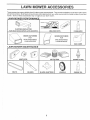
LAWN
OWER ACCESSORIES
These accessories were available when this lawn mower was produced: They are also available at most Sears retail outlets
and service centers. Most Sears stores can also order repair parts for you, when you provide the model number of your lawn
mower. Some of these accessories may not apply to your lawn mower.
LAWN MOWER
PERFORMANCE
CLIPPING DEFLECTOR
FOR REAR DISCHARGE LAWN MOWERS
MULCHER KITS
GRASS CATCHERS
FOR
REAR DISCHARGE
LAWN MOWERS
STABILIZER
GRASS CATCHERS
FOR
SIDE DISCHARGE
LAWN MOWERS
GAS CANS
LAWN MOWER MAINTENANCE
MUFFLERS
BELTS
AIR FILTERS
BLADES
BLADE ADAPTERS
5
SPARK PLUGS
WHEELS
ENGINE OiL
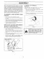
ASS
LY
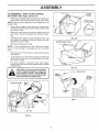
TO INSTALL
(See Fig° 2)
Read these instructions and this manual in its entirety
before you attempt to assemble or operate your new tawn
mower. Your new lawn mower has been assembled at the
factory with the exception of those parts left unassembled
for shipping purposes. All parts such as nuts, washers,
bolts, etc., necessary to complete the assembly have been
placed in the parts bag. To ensure safe and proper
operation of your lawn mower, all parts and hardware you
assemble must be tightened securely. Use the correct
tools as necessary to ensure proper tightness.
TO REMOVE
CARTON
LAWN
MOWER
ATTACHMENTS
Your lawn mower was shipped ready to be used as a
mulcher. To convert to bagging or discharging:
Open rear door and remove mulcher
mulcher plug in a safe place.
plug.
Store
You carl now install catcher or optionat clipping deflector.
,
FROM
To return to mulching operation, install mulcher plug
into discharge opening of mowen
Remove loose parts included with mower.
,
Cut down two end corners of carton and lay end panel
down flat,
,
Remove all packing matefiats except padding between
upper and lower handle and padding holding opera[or
presence control bar to upper handle.
•
Roll lawn mower out of carton and check carton thor°
eughiy for additional loose parts.
HOWTO SET UPYOUR
TO UNFOLD
HANDLE
LAWN MOWER
MULCHER
F_Go2
IMPORTANT: UNFOLD HANDLES CAREFULLY SO AS
NOT TO PINCH OR DAMAGE CONTROL CABLES.
•
Raise handles until lower handle section locks into
place in mowing position.
,
Remove protective padding, raise upper handle sec_
tien into place on lower handle and tighten both handle
knobs.
•
Remove handle padding holding operator presence
control bar to upper handle.
,
Your lawn mower handle can be adjusted for your
mowing comfort.
Refer to "Adjust Handle" in the
Service and Adjustment sect}on of this manual.
OPERATOR PRESENCE
CONTROL BAR _-
--":'_ "
_._)
PPER.ANOLE
////
LIFT UP
_iP-
l
PLUG
(See Fig. 1)
_////
catcher in place, Never attempt to o13proved
deflector
erate the clipping
fawn mower
with the or
reargrass
door
removed or propped open.
b,,
._-.
LIFT UP //"
_1" /7
_
CAUTION: Do not run your lawn mower
witt)out mutcher plug #'_ p}ace or ap-.
//
}h
iy
I/
|y;..'%,//
Xt& ,h. _
"-_,Y
.s&++_.2#..._../
.ow,°o.o..,o°
LOWER HANDLE
FiG, 1
•
ASSEMBLY
TO ASSEMBLE
AND
ATTACH
GRASS
LOWER
FRAME
CATCHER
(See Figs. 3A thru 4)
o insert leg of tubular frame through front opening of
grass catcher and thread frame into sewn hem of bag.
be fully seated)
(Frames rnust
NOTE: Keep bag hem gathered on the straight leg of the
tubular frame.
,
•
•
When frame comes out the other end of sewn hem,
immediately work the end of frame down inside the bag
as shown in inset.
Slide sewn hem evenly around the tubular frame until
both ends of frame are exposed out of the front opening.
Assemble tower frame to tubular frame as shown: Be
sure handle is outside of bag and frames are fully
seated as shown Jn inset.
/
FiG, 3B
LOWER FRAME HANDLE
Slip vinyl bindings over frame.
NOTE: If vinyl bindirTgs are too stiff, hold them in warm
water for a few minutes. If bag gets wet, let it dry before
using.
•
TUBULAR
FRAME
\
CIosetheflip lid. Flip lid must be closed while operating
lawn mower.
Lift the rear door on the mower housing and place the
grass catcher frame onto the formed tabs on the rear
door hinge brackeL
o
The grass catcher is secured to the lawn mower
housing when the rear door is towered onto the grass
catcher frame.
FtG, 3C
GRASS
CATCHER
FRAME
TUBULAR
FRAME
SEWN
FiG. 4
SEWN HEM
FLIP LID
FIG. 3A
OPERATION
KNOW' YOUR LAWN MOWER
READ THIS OWNER'S MANUAL AND SAFETY RULES BEFORE OPERATING YOUR LAWN MOWER, Compare the
illustrations with your lawn mower to familiarize yourself with the location of various controls and adjustments. Save this
manual for future reference.
These symbols
their
may appear on your lawn mower or in literature
supplied with the product.
Learn and understand
meaning.
CAUTION
OR WARNING
ENGINE
ON
ENGINE
OFF
ENGINE ZONE CONTROL
STARTER
FAST
SLOW
CHOKE
CABLE
FUEL
OIL
DANGER KEEP HANDS
AND FEET AWAY
OPERATORPRESENCE
HANDLE
DRIVE CONTROL
HANDLE
CONTROL, BAR
LEVER
KNOB
ENGINE OIL CAP W/DiPSTICK
GRASSCATCHER
DRWECOVER
MULCHERPLUG
GASOLt_
ENGINE SPEED CONTROL
PRIMER
\_
HOUSING
WHEEL ADJUSTER
(ON EACH WHEEl..)
MEETS
CPSC SAFETY
REQUIREMENTS
Sears rotary walk-behind power lawn mowers conform to the safety standards of the American National
and the U.S, Consumer Product Safety Commission. The blade terns when the engine is running.
OPERATOR PRESENCE CONTROL
- must be held
down to the handle to start the engine. Release to stop the
engine.
Standards
Institute
DRiiVE CONTROL LEVER - used to engage power-propelled forward motion of tawn mower,
ENGINE SPEED CONTROL - located on the side of the
engine which al!ows you to select either fas[ (_'_) or slow
(_)
engine speed.
PRIMER o pumps additional fuel from the carburetor tO the
cylinder for use when starting a cold engine.
STARTER HANDLE - used for starting the engine.
8
MULCHER PLUG- must be removed to convert to bagging
or discharging operation.
OPERATION
The operation of any lawn mower can result in foreign objects thrown into the eyes, which can
result in severe eye damage. Always wear safety glasses or eye shields while operating your
lawn mower or performing any adjustments or repairs, We recommend a wide vision safety
mask over the spectacles or standard safety glasses.
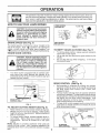
HOWTO
USE YOUR LAWN MOWER
LOWER WHEELS
FOR HIGH CUT
PLATE TAB
CAUTION: Do not run your lawn mower
without muicher plate in place and door
closed or without an approved clipping
deflector
or grasscatcher
in place.
Never attempt
to operate the lawn
mower with the rear door removed or
propped open.
ENGINE
SPEED
RAISE WHEELS
FOR LOW CUT
(See Fig. 5)
The engine speed is controlled by a lever located on the
side of the engine. High (4)
position is for starting the
engine, normal cutting, and better grass bagging. Low
(_) position is for lig ht cutting, trimming and fuel'economy.
ENGINE ZONE
FIG. 6
TO EMPTY GRASS
,
CONTROL
•
CAUTION: Federal regulations require
an engine control to be installed on this
lawn mower in order to minimize the
risk of blade contact injury, Do not
under any circumstances
attempt to
defeat the function of the operator control. The b_ade turns when the engine is
running.
Your lawn mower
ence control bar
positioned behind
operate the lawn
•
CATCHER
(See Fig. 7)
To remove grass catcher, release operator presence
control bar to stop engine.
Lift up rear door and remove the g rass catcher by the
handle.
Do not drag the bag when emptying;
it will cause
unnecessary wear.
is equipped with an operator preswhich requires the operator to be
the lawn mower handle to start and
mower.
FiG. 7
DRIVE CONTROL
=
•
ENGINE SPEED
CONTR,
PRIMER
,
FIG, 5
TO ADJUST
CUTTING
HEIGHT
(See Fig. 6)
Raise wheels for low cut and lower wheels for high cut.
Wheels are set in low cut for shipping. Adjust cutting
height to suit your requirements. Medium position is
best for most lawns,
To change cutting height, squeeze adjuster lever toward wheel
Move wheel up or down to suit your
requirements.
Be sure all wheels are in the same
setting.
NOTE: Adjuster is properly positioned when plate tab
inserts into hole in lever. Also, 9-position adjusters (if so
equipped) allow lever to be positioned between the plate
tabs.
(See Fig, 8)
Self-propelling is controlled by holding the operator
presence control bar down to the handle and pushing
the drive control lever forward until it clicks; then
release the lever.
Forward motion will stop when the operator presence
control bar is released. To stop forward motion without
stopping engine, release the operator presence control
bar slightly until the drive control disengages. Hold
operator presence control bar down to handle to continue mowing without self-propelling.
To keep drive control engaged when turning corners,
push down on handle and lift front wheels off ground
while turning lawn mower.
OPERATOR
•
,
_, \
CONTROL
,
!
PRESENCE
BAR
\
),
TO ENGAGE
DRIVE CONTROL
9
DRIVE CONTROL
DISENGAGED
FIG. 8
OPERATION
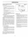
BEFORE
OIL (See
STARTING
ENGINE
GASOLINE
FILLER
ENGINE OIL CAP
WIDtPSTICK
CAP
Fig. 9)
Your lawn mower is shipped without oil in the engine.
Be sure mower is level and area around oil flit is clean,
"
Remove engine oit cap w/dipstick and fitl to the full tine
on the dipstick.
Use27ozs. of oil. Fortype and grade of oil to use, see
"ENGINE" in Customer Responsibilities section of this
manual.
o
,
Pour oil slowly. Do not over fill.
Check oi! level before each use. Add oil if needed. FIll
to full line on dipstick.
o
To read proper leve!, tighten engine oil cap each time.
F_Go9
Reinstall engine oil cap and tighten.
Cbangethe oil afterevery 25 hours of operation oreach
season. You may need to change the oil more often
under dusty, dirty conditions.
MOWING T PS
Under certain conditions, such as very tall grass, it may
be necessary to raise the height of cul to reduce
pushing effort and to keep from overloading the engine
and leaving dumps of grass clippings.
GAS (See Fig, 9)
Fill fuel tank. Use fresh, clean, regular unleaded
gasoline with a minimum of 87 octane. Do not mix oil
with gasoline. Purchase fuel in quantities that can be
used within 30 days to assure fuel freshness.
IMPORTANT: WHEN OPERATING IN TEMPERATURES
BELOW32°F(0°C), USE FRESH, CLEAN WINTER GRADE
GASOLINE TO HELP INSURE GOOD COLD WEATHER
STARTING.
WARNmNG: Experience indicates that alcohol blended
Iuels (called gasohoI or using ethanol or methanol) can
attract moisture which leads to separation and formation of
acids during storage. Acidic gas can damage the fuel
system of an engine while in storage. To avoid engine
problems, the fuel system should be emptied before storage of 30 days or longer. Drain the fuel tank, start the
engine and let it run until fuel lines and carburetor are
empty. Use fresh fuel next season. See Storage Instructions for additional information.
Never use engine or
carburetor cleaner products in fuel tank or permanent
damage may occur.
o
To stop engine, release operator presence control bar.
•
For better grass bagging and most cutting conditions,
the engine speed should be set in the fast (@) position.
,
When using a rear discharge tawn mower in moist,
heavy grass, clumps of cut grass may not enter the
grass catcher. Reduce ground speed (pushing speed)
and/or run the lawn mower over the area a second time.
Keep top of engine around starter clear and clean of
grass clippings and chaff. ]"hiswilt help engine airflow
and extend engine life.
Pores in cloth grass catchers can become fitfed with dirt
and dust with use and catchers will collect tess grass.
To prevent this, regularly hose catchers off with water
and Iet dry before using.
To start a cold engine, push primerfive (5) times before
trying to start. Use a firm push. This step is not usually
necessary when starting an engine which has already
run for a few minutes.
Move engine speed control lever to fast (,f_) position.
Hold operator presence control bar down to the handle
and pull starter handle quickly. Do not allow starter
rope to snap back.
For extremely heavy cutting, reduce the width of cut
and raise the rear of the lawn mower housing one (t)
wheel adjuster setting higher than the front for better
discharge of grass.
tf a trai! of grass clippings is teft on the right side of a rear
discharge lawn mower, mow in a clockwise direction
with a small overlap to collect the clippi_gs on Ihe next
pass.
TO START ENGmNE
o
-
NOTE: In cooler weather it may be necessary to repeat
priming steps. In warmer weather oveS priming may cause
flooding and engine will not start, lf;_!ou do flood engine,
wait a few minutes before attempting to start and do not
repeat priming steps.
10
OPERATION
MULCHING
MOWING TIPS
IMPORTANT:
FOR BEST PERFORMANCE,
KEEP
MOWER HOUSING FREE OF BUILT-UP GRASS AND
TRASH.
SEE
"CLEANING"
IN
CUSTOMER
RESPONSIBILITIES SECTION OF THIS MANUAL.
"
The special mulching blade will recut the grass clippings many times and reduce them in size so that as
they fall onto the fawn they wil! disperse into the grass
and not be noticed.
Also, the mulched grass will
biodegrade quickty to provide nutrients for the lawn.
Always mulch with your highest engine (blade) speed
as this will provide the best recutting action of the
blades.
-
Avoid cutting your lawn when it iswet. Wet grass tends
to form clumps and interferes with the mulching action,
The best time to mow your lawn is the early afternoon.
At this time the grass has dried and the newlycut area
wilt not be exposed to the direct sun.
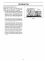
*
For best results, adjust the lawn mower cutting height
so that the lawn mower cuts off only the top one-third
of the grass blades (See Fig. 10). If the lawn is
overgrown it will be necessary to raise the height of cut
to reduce pushing effort and to keep from overloading
the engine and leaving clumps of mulched grass. For
extremely heavy mulching, reduce your width of cut by
overlapping previously cut path and mow slowly.
MAX II3
FtG. 10
Certain types of grass and grass conditions may require that an area be mulched a second time to completely hide the clippings. When doing a second cut,
mow across or perpendicular to the first cut path.
,
Change your cutting pattern from week to week. Mow
north to south one weekthen change to east towest the
next week, This wil! help prevent matting and graining
of the lawn.
11
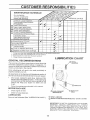
CUSTOiViE
MAINTENANCE
ESPONSIBILITIES
SCHEDULE
FiLL IN DATES
AS YOU COMPLETE
REGULAR SERVICE
SERVICE
DATES
Check for Loose Fasteners
Clean/Inspect Grass Catcher
(If Equipped)
Clean Lawn Mower
Clean Under Drive Cover
(Power-Propelled Mowers)
M
O
W
drive be!t/pulleys
E Check
Power-Propelled Mowers}
R ChecWSharpen/Reptace Blade
Lubrication Chart
Clean Battery/Recharge
Electric Start
w
E Check Engine Oil Level
N Change Engine Oil
G Clean Air Filter
Inspect Muffler
Ctean
or RepJace Spark Plug
N
E Reptace Air Filter Paper Cartridge
1
2
3
4
V'2
- Change more often when operating under a hear ,Ioad or in high ambient
- Service more often when operating
in dirty or dusty conditions.
o Replace
blades
more often when mowing in sandy soil.
- Charge 48 hours at end of season.
GENERAL
temperatures.
LUBRICATION
RECOMMENDATIONS
CHART
(9 WHEEL
ADJUSTER
The warranty on this lawn mower does not cover items that
have been subiected to operator abuse or negligence. To
receive ful! value from the warranty, operator must maintain
mower as instructed in this manual.
Some adjustments wilt need to be made periodically to
properly maintain your unit.
All adjustments in the Service and Adjustments section of
this manual should be checked at least once each season.
i il
_ !i!_
o
Once a year, replace the spark plug, replace air filter
eiement and check blade for wear. A new spark plug
and clean/new air filter element assures proper air-fuet
mixture and helps your engine run better and last
longer'.
Follow the maintenance schedule in this manual,
BEFORE
EACH
I ENGINE O_L
USE
DLE BRACKET
MOUNTING PiN
Check engine oil level.
,
Check for loose fasteners.
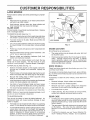
LUBRICATION
Keep unit well lubricated (See "LUBRICATION
CHART").
i
REAR DOOR
HINGE
O
SPRAY LUBRICANT
Q
REFER TO CUSTOMER RESPONSIBILITIES
"ENGIN_:_" SECTION,
IMPORTANT:
DO NOT OIL OR GREASE PLASTIC WH EEL
BEARINGS,
VISCOUS
LUBRICANTS
WILL ATTRACT
DUST AND DIRT THAT WILL SHORTEN THE LIFE OF
THE SELF LUBRICATING
BEARINGS, IFYOU FEEL THEY
MUST BE LUBRICATED,
USE ONLYA DRY, POWDERED
GRAPHITE
TYPE LUBRICANT
SPARINGLY.
12
CUSTO
LITIES
LAWN MOWER
BLADE
ADAPTER
AIways observe safety rules when performing any maintenance.
SHAFT
KEYWAY
TIRES
Keep tires free of gasoline, oil, or insect control chemicals which can harm rubber.
*
Avoid stumps, stones, deep ruts, sharp objects and
other hazards that may cause tire damage.
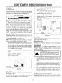
BLADE
CARE
Forbest results, mowerbtademust
bent or damaged blades.
bekeptsharp.
Replace
TO REMOVE BLADE (See Fig. t 1 )
,
,
"CRANKSHAFT
Disconnect spark plug wire from spark plug and place
wire where it cannot come in contact with spark plug.
Turn lawn mower on its side. Make sure air filter and
carbu_'etor are up.
HARDENED
WASHER
LOCK WASHER
Use a wood block between blade and mower housing
to prevent blade from turning when removing blade
bolt,
Remove blade bolt by turning counter-clockwise.
a 9/16" box or open-end wrench.
,
Remove blade and attaching hardware
washer and hardened washer).
GRASS
•
NOTE: Remove the blade adapter and check the key
inside hub of blade adapter. The key must be in good
condition to work properly. Replace adapter if damaged.
TO REPLACE BLADE (See Fig. 1 t)
•
Position the blade adapter on the engine crankshaft.
Be sure key in adapter and crankshaft keyway are
aligned.
•
Be sure the trailing edge of blade (opposite sharp
edge) is up toward the engine.
Install the blade bolt with the tockwasher and hardened
washer into blade adapter and crankshaft.
Use block of wood between blade and lawn mower
housing and tighten the blade bolt, turning clockwise.
Check your grass catcher often for damage or deterioration. Through normal use it will wear. If catcher
needs replacing, replace only with a manufacturer
approved replacement catcher. Give the lawn mower
model number when ordering.
DRIVE WHEELS
Check front drive wheels each time before you mow to be
sure they move freely.
The wheels not turning freely means trash, grass cuttings,
etc. are in the drive wheel area and must be cteaned to free
drive wheels.
tf necessary to clean the drive wheels, check both front
wheels,
•
The recommended tightening torque is 35-40 ft. lbs.
IMPORTANT: BLADE BOLT IS GRADE 8 HEATTREATED.
NOTE: We do not recommend sharpening
you do, be sure the blade is balanced.
CATCHER
The grass catcher may be hosed with water, but must
be dry when used.
(bolt, lock
Position blade on the blade adapter aligning the two (2)
holes in the blade with the raised lugs on the adapter.
ADAPTER
(If purchased as an accessory)
Use
,,
BLADE
FroG.11
Protect your hands with gloves and/or wrap blade with
heavy cloth.
•
TRAILING
EDGE
.
Remove hubcaps, hairpin cotters and washers.
,
Remove wheels from wheel adjusters.
,
Remove any trash or grass cuttings from inside the
dust cover, pinion and/or drive wheel gear teeth.
-
Put wheels back in place.
If after cleaning, the drive wheels do not turn freely,
contact your nearest authorized service center.
blade - but if
TO SHARPEN BLADE
GEAR
Care should be taken to keep the blade balanced. An
unbalanced blade will cause eventual damage to lawn
mower or engine.
•
To keep your drive system working properly, the gear
case and area around the drive should be kept clean
and free of trash build-up. Clean under the drive cover
twice a season.
o
The gear case is filled with lubricant to the proper level
at the factory, The only time the lubricant needs
attention is if service has been performed on the gear
case.
.
If lubricant is required, use only Texaco Starplex Premium 1 Grease, Part No. 750355. Do not substitute.
The blade can be sharpened with a file or on a grinding
wheel. Do not attempt to sharpen while on the mower.
-
To check blade balance, drive a nailinto a beam orwall.
Leave about one inch of the straight nail exposed.
Piace center hole of blade over the head of the nail, If
blade is balanced, it should remain in a horizontal
position. If either end of the blade moves downward,
sharpen the heavy end until the blade is balanced.
13
CASE
CUSTOMER
RESPONSIBILITIES
ENGINE
TO CHANGE AIR FILTER (See Fig. t3)
•
Loosen cover screw,
LUBRiCATiON
Use only high quality detergent oil rated with API service
classification SF or SG. Select the oiI's SAE viscosity grade
according to your expected operating temperature,
Swing cover down and remove from hinge.
Pull paper filter out of air cleaner body.
Clean air cleaner cover and body.
Install a new paper filter.
Reinstall cover to air cleaner body. Be sure hinge is
assembled properly.
Swing cover up and tighten cover screw. (DO not
overtighten).
•
•
,
SAE VISCOSITY GRACES
•
.20 _
.30 _
TEMPERATURE
0_
30 _
_t0_
RANGE
32 _ 40 °
0"
ANTICIPATED
80 °
60 °
10_
BEFORE
20°
NEXT
30 °
40 °
AIR FILTER
COVER
OIL CHANGE
NOTE: Although multiwiscosity oils (5W30, 10W30 etc.)
improve starting in cold weather, these multi-viscosity oils
will result in increased oi! consumption when used above
32°F. Check your engine oil level more frequently to avoid
possible engine damage from running low on oil,
COVER
SCREW
J
HINGE
Change the oil after every 25 hours of operation or each
season. You may need to change the oil more often under
dusty, dirty conditions,
PAPER
FILTER
Check the crankcase oil level before starting the engine
and after each five (5) hours of continuous use, Tighten oil
plug securely each time you check the oil level,
FIG. 13
MUFFLER
TO CHANGE ENGINE OIL (See Fig. 12)
Inspect and replace corroded muffler as it could create a
fire hazard and/or damage.
NOTE: Before tipping lawn mower to drain oil, drain fuel
tank by running engine until fue! tank is empty.
.
.
SPARK
PLUG
Disconnect spark plug wire from spark plug and place
wire where it cannot come in contact with spark plug.
Change your spark plug each year to make your engine
start easier and run better. Set spark plug gap at ,030 inch.
Remove engine oil cap; lay aside on a clean surface,
CLEANING
.
Tip lawn mower on its side and drain eli into a suitable
container. Rock lawn mower back and forth to remove
any oil trapped inside of engine.
°
Wipe off any spilled oil on lawn mower and on side of
engine_
IMPORTANT:
FOR BEST PERFORMANCE,
KEEP
MOWER HOUSING FREE OF BUILT-UP GRASS AND
TRASH. CLEAN THE UNDERSIDE OF YOUR MOWER
AFTER EACH USE,
,
Fill engine with oi!. Fill only to the "FULL" line on the
dipstick. DO NOT OVER FILL.
o
Replace engine oil cap.
•
Reconnect spark plug wire to spark plug.
]
,_ _
_
CONTAINER
FIG. t2
AiR FHLTER
from spark plug and place wire where it
cannot come in contact with the spark
,
Turn lawn mower on its side, Make sure air filter and
carburetor are up. Clean the underside of your lawn
mower by scraping to remove build-up of grass and
trash.
•
Clean engine often to keep trash from accumulating. A
clogged engine runs hotter and shortens engine life.
-
Keep finished surfaces and wheels free of atl gasoline,
oil,etc.
-
We do not recommend using a garden hose to clean
lawn mower unless the electrical system, muffler, air
filter and carburetor are covered to keep water out.
Water in engine can result in shortened engine life.
Your engine will not run properly and may be damaged by
using a dirty air filter.
CLEAN
Replace the _ir filter every year, more often if you mow in
very dusty, dirty conditions. Do not wash air filter.
Clean under drive cover at least twice a season. Scrape
underside of cover with putty knife or similar toot to remove
any build-up of trash or grass on underside of drive cover.
!4
UNDER
DRIVE COVER
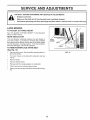
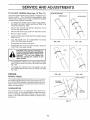
SERVICE AND ADJU
ENTS
CAUTION:
BEFORE PERFORMING ANY SERVICE OR ADJUSTMENTS:
Release control bar,
Make sure the blade and al! moving parts have completely stopped,
,
Disconnect spark plug were from spark plug and place where it cannot come in contact with plug.
LAWN MOWER
TO ADJUST
CUTTING
See "TO ADJUST CUTTING
section of this manual.
HEIGHT
HEIGHT" in the Operation
REAR DEFLECTOR
The rear deflector, attached between the rear wheels of
your lawn mower, is provided to minimize the possibility
that objects wilt be thrown out the rear of the lawn mower
into the operator's mowing position. If the rear deflector
becomes damaged, it should be replaced.
TO REMOVE/REPLACE
DRIVE
COVER
BELT
!
PRESS
DRIVE BELT
(See Fig, 14)
•
•
,
Remove drive cover. Remove belt by pushing down on
gear case pulley.
Turn lawn mower on its side with carburetor and fuel
cap up.
Remove blade.
FIG. 14
Remove debris shield.
-
Remove belt from engine pulley on crankshaft.
•
Install new belt by reversing above steps.
•
Always use factory approved belt to assure fit and tong
life.
15
SERVICE
TO ADJUST
HANDLE
(See Figs,
AND ADJUSTMENTS
15 Thru 17)
SHIPPING POSITION
Your tawri mower handfe can be raised or lowered for your
mowing comfort.
Four (4) positions are available: high,
medium high, medium Jow and low. HandIes are shipped
mounted in the medium low position.
*
To change from medium towto medium high position,
the upper and lower handle sections will have to be
turned over (See Fig. t5B).
,
Remove the controls and operator presence control
bar from the upper handle.
,
Remove the starter rope guide from the lower handle.
,
,
Remove hairpin cotters.
Disconnect the iower handle from the handle brackets
(See Fig. 17).
Turn the handle over and reassemble
cotters that have been removed.
MEDIUM LOW
MEDIUM HIGH
the hairpin
,
Reassemble the starter rope guide.
o
Reassemble the controls and the operator presence
control bar to the upper handle.
FiG. 15A
FiG, 18B
LOW
HiGH
CAUTION: The operator presence contro_ bar must pivot freely to permit blade
brake engagement when control bar is
released,
Do not over tighten the
fasteners holding the controls to the
upper handled
To change from medium low to high position only the
upper handle section will have to be turned over (See
Fig. 16A).
=
To change from medium low to low position, only the
lower handle section will have to be turned over (See
Fig. 16B).
ENGINE
ENGINE SPEED
FIG, 16A
Your engine speed has been factory set. Do not at[erupt
to increase engine speed or it may result in personat i__jury.
If you believe that the engine is running too fast ortoo slow,
take your lawn mower to an authorized service center for
repair and adjustment.
SQUEEZE
TO REMOVE
FIG. t6B
LOWER HANDLE
\
CARBURETOR
HANDLE
BRACKET
Your carburetor has a non-adjustable fixed main jet for
mixture control. If your engine does not operate properly
due to suspected carburetor problems, take your lawn
mower to an authorized service center for repair and/or
adjustment.
HAIRPIN CLIP
FiG. 17
t6
....
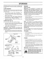
STORAGE
Immediately prepare your lawn mower for storage at the .....
end of the season or if the unit will not be used for 30 days
or more.
ENGINE
LAWN MOWER
IMPORTANT:
IT tS IMPORTANT TO PREVENT GUM
DEPOSITS FROM FORMtNG IN ESSENTIAL FUEL
SYSTEM PARTS SUCH AS CARBURETOR, FUEL FILTER,
FUEL HOSE, OR TANK DURING STORAGE.
ALSO,
EXPERIENCE INDICATES THAT ALCOHOL BLENDED
FUELS (CALLED GASOHOL OR USING ETHANOL OR
METHANOL) CAN ATTRACT MOISTURE WHICH LEADS
TO SEPARATION AND FORMATION OF AC!DS DURING
STORAGE.
ACIDIC GAS CAN DAMAGE THE FUEL
SYSTEM OF AN ENGINE WHILE IN STORAGE.
When lawn mower is to be stored for a period of time, clean
it thoroughly, remove all dirt, grease, leaves, etc. Store in
a clean, dry area.
,
Clean entire lawn mower (See "CLEANING" in the
Customer Responsibilities section of this manual).
,
Lubricate as shown in the Customer Responsibilities
section of this manual.
o
Be sure that all nuts, bolts, screws, and pins are
securely fastened. Inspect moving parts for damage,
breakage and wear. Replace if necessary.
*
*
,
(See Fig. 18)
,
Squeeze the bottom ends of the lower handle toward
each other until the lower handle clears the handle
bracket, then move handle forward.
,
Loosen upper handle mounting bolts enough to allow
upper handle to be folded back.
IMPORTANT:
WHEN FOLDING THE HANDLE FOR
STORAGE OR TRANSPORTATION, BE SURE TO FOLD
THE HANDLE AS SHOWN OR YOU MAY DAMAGE THE
CONTROL CABLES.
o
Never use engine or carburetor cleaner products in the
fuel tank or permanent damage may occur.
Use fresh fuel next season.
NOTE:
Fuel stabilizer is an acceptable alternative in
minimizing the formation of fuel gum deposits during storage. Add stabilizer to gasoline in fuel tank or storage
container. Always follow the mix ratio found on stabilizer
container. Run engine at least 10 minutes after adding
stabilizer to allow the stabilizer to reach the carburetor. Do
not drain the gas tank and carburetor if using fuel stabilizer.
You can fold your lawn mower handte for storage.
z
Drain the fuel tank=
Start the engine and let it run until the fuel !ines and
carburetor are empty.
Touch up all rusted or chipped paint surfaces; sand
lightly before painting.
HANDLE
FUEL SYSTEM
ENGINE
OIL
Drain oil (with engine warm) and replace with clean engine
oil. (See "ENGINE"
in the Customer Responsibilities
section of this manual).
When setting up your handle from the storage position,
the lower handle will automatically lock into the mowing
position.
CYLINDER
Remove spark plug.
Pour one ounce (29 ml) of oil through spark plug hole
!nto cylinder.
LOWER HANDLE
Pu!! starter handle slowly a few times to distribute oit.
*
Replace with new spark plug.
OTHER
SQUEEZE TO
FOLD
o
Do not store gasoline from one season to another.
,
Replace your gasoline can if your can starts to rust.
Rust and/or dirt in your gasoline wilt cause problems.
If possible, store your unit indoors and cover it to give
protection from dust and dirt.
HAIRPIN
COTTER
=
Cover your unit with a suitable protective cover that
does not retain moisture. Do not use plastic. PIastic
cannot breathe which al!ows condensation to form and
will cause your unit to rust.
IMPORTANT: NEVER COVER MOWER WHILE ENG!NE
AND EXHAUST AREAS ARE STILL WARM.
OPERATOR PRESENCE
CONTROLBAR
UPPER HANDLE
FOLDFORWARD
FORSTORAGE
inside a build-
FOLD BACKWARD
flame or spark. Allow the engine to coo}
MOWING
POSITION
LOWER
HANDLE
FiG. t8
17
i
SERVICE
18
OTES
TRO
PROBLEM
LESHOOTING
CAUSE
Does not start
Loss of power
Poorcut-uneven
POINTS
CORRECTION
t.
2.
3.
4.
Dirty air filter.
Out of fuel
Stale fuel.
Waterin fue!.
1.
2.
3.
4.
5.
6.
7.
8.
9.
Spark plug wire is disconnected.
Bad spark plug.
Loose blade or broken blade adapter.
Control bar in released position
Control bar defective
5.
6.
7.
8.
9.
Clean/replace air filter.
Fill fuel tank.
Drain tank and refill with fresh clean fuel.
Drain fuel tank and carburetorand refill tank with fresh
gasoline.
Connect wire to ptug.
Replace spark plug.
Tighten blade bolt or replace blade adapter.
Depress control bar to handle.
Replace control bar.
!.
1.
Set in "Higher Cut" position.
2.
3.
4.
5.
6.
Rear of lawn mower housing/blade dragging
in heavy grass.
Cutting too much grass.
Dirty air filter.
Buildup of grass, leaves and trash under mower.
Too much oil in engine.
Walking speed too fast.
2.
3.
4.
5.
Set in "Higher Cut" positEon.
Clean/replace air filter.
Clean underside of mower housing.
Check oil level.
6.
Cut at slower walking speed.
1.
2.
3.
4.
Worn, bent or loose blade.
Wheel heights uneven.
Low engine speed.
Buildup of grass, leaves, and trash under mower.
1.
2.
3.
4.
Replace blade. Tighten blade bott.
Set at1wheels at same height.
Set engine speed control in fast position.
CIean underside of mower housing.
!.
2.
Replace blade. Tighten blade bolt.
Contact authorized service center!department.
Depress control bar to upper handle before
pulling starter rope.
Contact authorized service center/department.
Replace blade adapter.
Move lawn mower to cut grass or to hard surface
to start engine.
m
Excessive
vibration
i.
Worn, bent or loose blade.
2.
Bent engine crankshaft.
!.
Engine flywheel brake is on when control bar is
released.
1.
2.
3.
4.
Bent engine crankshaft
Blade adapter broken.
Biade dragging in grass.
2.
3.
4.
Loss of drive
1.
2.
Drive wheels not turning with drive control engaged.
Belt not driving.
1.
2.
Adjust or replace drive control cable, if broken.
Put belt on pulleys or replace belts if broken.
Grass catcher not filling
(If so equipped)
1.
2.
Cutting height too low.
Lift on bIade worn off.
3.
4.
Catcher not venting air.
Low engine speed.
1.
2.
3.
4.
Raise cutting height.
Replace blade.
Clean grass catcher.
Set engine speed control in fast position.
1.
2.
Raise cutting height.
Raise rear of lawn mower housing one (t)
setting higher.
Empty grass catcher.
Adjust handle height to suit.
Starter rope hard to pull
1,1==
Hard to push
__
1.
2.
3.
4,
•
,!
,il
Grass is too high or wheel height is too low.
Rear of lawn mower housing/blade dragging
in grass.
Grass catcher too full.
Handle height position not fight for you.
t9
i
3.
4.
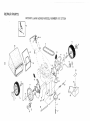
REPAIR PARTS
ROTARY LAWN MOWER _IODEL NUMBER
91 I°$1,301
11
!
54
18
t4
t0
#O
#O
25
2.6\
14
I
t
4t
I0
8
13
t2
I
REPAIR PARTS
ROTARY LAWN MOWER MODEL NUMBER
KEY
NO,
1
2
3
4
5
6
8
9
10
11
12
13
14
15
16
18
z
PART
NO.
145755
48385
63601
144929
146527
150495
150182
145212
88446
150340
12000058
137054
88080
88118
67725
701037
DESCRIPTION
Controf Cable Assembly
Control Head Kit
Locknut #10-24
HexWasher Head Screw 1/4-20 x 2.12
V-Belt
Spring Retainer
Hubcap
Locknut
Nylon Bushing
Wheel & Tire Assembly
E-Ring
Pinion
Dust Cover
Felt Washer
Washer 1/2x 1-1/2 x.134
Selector Knob
KEY
NO.
PART
NO,
25
26
28
31
32
33
35
36
37
38
40
41
53
54
55
57
152903
143603
702806
132010
137052
48386
151521
702511
137090
STD541425
75192
151520
144747
154870
86012
144748
917.377301
DESCRIPTION
Drive Cover Decal
Pan Head Tapping Screw #10-24 x 2-3/4
Drive Cover
Hex Flange Nut
Drive Pulley
Drive Control Cable Kit
Wheel Adjuster Assembly (Left)
Gear Case Assembly
Spring
Locknut 1/4-20
Spring
Wheel Adjuster Assembly (Right)
Frame Throat
Grassbag Assembly
Driveshaft Cover
Frame Tube
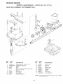
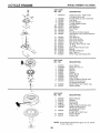
REPAIR PARTS
ROTARY LAWN MOWER _ * MODEL
GEAR CASE ASSEMBLY
PART NUMBER
NO. 917.377301
70251t
J
jJ
J
17
15
14
10
KEY
NOo
PART
NOo
!
2
3
4
6
17490416
137055X004
137053
57072
48373
7
8
9
t0
77881
137051
137074
57079
DESCRIPTION
Tapping Screw 114-20 x 1-1/4
Engagement Bracket
Shifter
Seal
Gear Case 14alves Kit (Includes Key
Nos, 4, 5, and 7)
Bearing
Worm Shaft
Drive Shaft
Hardened Washer
KEY
NO,
PART
NO.
DESCRIPTION
11
t2
13
t4
t5
16
17
18
19
131484
700343
86447
137050
750436X
750369
12000003
850848
81585X004
Clutch Yoke
Bushing
PLug
Helical Gear
Clutch Jaw
Grease
E-Ring
Hi-Pro Key
Spring Bracket
NOTE:
24
Att component dimensions given in U.S, inches.
t inch = 25.4 mm
SERVICE
25
NOTES
MODEL
NUMBER
143.976600
9O0
416
151A
12
240
,135
130'
35O
.243B
25t
26
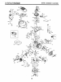
______4"_-YGLE
ENGINE
MODEL
NUMBER
!
KEY PART
NO. NO.
1
2
6
7
9
10
11
12
14
1{5
:16
17
18
!9
20
25
36t77
27652
36059
36005A
590568
36002
36003
32447
28277
36006
36008
31335
651018
36103
36010
36186
26
30
40
40
40
41
41
650802
36185
36073
36074
36075
36070
36071
41
36072
42
42
42
43
45
46
48
5O
52
69
70
72
73
75
80
81
82
36076
36O77
36078
20381
36023A
32610A
36030
36031A
29914
36032A
36194
30572
28833
36010
30574A
30590A
30591
36057
36034
650924
611154
611155
611156
650815
650816
34443A
610118
651007
36054
36061
36187
36471
36472
293!4B
293!5C
6021A
35395
31672
31673
40016
27234A
32755
30200
650925A
83
85
86
89
9O
9t
92
93
!co
!0t
t03
t"_o
ti9
120
125
!25
126
126
t 3O
t35
150
15!
I5iA
t69
i7)
t74
177
!!
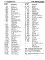
DESCRIPTION
Cylinder (incL 2,10,t2,20 & 125)
Dowel Pin
Breather Element
* Breather Cover & Gasket
Screw, 10-24 x3/4"
Breather Valve Body
Check Valve
Breather Tube
Flat Washer
Governor Rod (Machined)
Governor Lever
Governor Lever Clamp
Screw, Torx'r-15, 8-32 x 19/64"
Governor Spring
Oil Seal
Blower Housing Baffle Assay.
(InclJ95)
Screw, t/4-20 x 5/8"
Crankshaft
Piston, Pin,Ring Set (Std.)
Piston, Pin,Ring Set (.010 OS)
Piston, Pin,Ring Set (.020 OS)
Piston & Pin Ass'y.(Std.) (inc!. 43)
Piston & Pin Ass'y.
(.0t00S)(Incl.43)
Piston & PinAss'y.
(.020 OS)(incl.43)
Ring Set (Std.)
Ring Set (.0!00S)
Ring Set (.020 OS)
Piston Pin NetainingRing
Connecting Rod Assy. (Incl. 46) .
Connecting Rod Bolt
Valve Lifter
Camshaft (MCR)
Oil Pump Ass'y,
* Mounting Flange Gasket
Mounting Flange (Incl. 72 thru 85)
Oil Drain Plug (Incl. 73)
Drain Plug Gasket
OiI Seal
Governor Shaft
Washer
Governer Gear Ass'y. (Inct,81)
Governor Spool
Idler Gear
Screw, 1/4-20 x t-9/t6"
Flywheei Key
Flywheel
Flywheel Fan
Belleville Washer
Flywheel Nut
Solid State ignition
Spark Plug Cover
Screw, TorxT-15, 10-24x 15/t6"
Ground Wire
* Cylinder Head Gasket
Cylinder Head
Exhaust Valve (St&) (lncL 151)
Exhaust Valve (!/32" OS)
Intake Valve (Std;! (lncL 151)
Intake Valve (1/32 OS)
Screw, 5/I6-!8 x 1-t/2"
Resistor Spark Plug (RJ19LM)
Valve Spring
Lower Valve Spring Cap
Intake Valve Seal
* Valve Spring Box Gasket
Valve Spring Box Cover
Screw, 10-24 x 9/16"
Carburetor Mounting Stud
KEY
NO.
PART
NO.
184
186
187A
190
t9tA
t92
t93
194
195
198
!99
202
203
204
205
215
239
240
243B
245
250
25I
25IA
255
256
260
26t
262
263A
275
276
277
285
2r47
290
292
300
30t
305
307
308
310
346A
347
350
370A
370B
3700
380
390
400
36183
36009
36195
36013
36012
36016
36015
36014
610973
36017
360t8
36482
31342
651029
651030
36051
36048
36190
651041
36046
36191
650928
650933
36193
650983
36188
650737
650929
36192
36107
36043
650927
34449A
650926
34357
26460
36189
36246
36063
35499
36040
36064
28763
650898A
36045
36261
36155
36861
63267tA
590702
360620
416
36085
417
900
650760
--
900
--
143.976600
II I
DESCRIPTION
Carburetor Gasket
Governor Link
Air Baffle
Brake Lever Ass'y.
Brake Controi Lever
Brake Control Lever Link
Brake Spring
Retaining Ring
Termina! Ass'y,
Brake Control Lever Spring
Brake Lever Bushing
Compression Spring
Compression Spring
Screw, 5-40 x 7/16"
Screw, Torx T-!0, 6-32 x 17/32"
Control Knob
* Carburetor To Air Cleaner Gasket
Air C_eaner Body (IncL239 & 350)
Air Oteaner Stud
Air Cleaner Filter
Air Cleaner Cover
Lock Nut !/4-20
Wing Nut, 1/4-20
Control Plate
Screw, 8-32 x 2!/64"
Blower Housing
Screw, !/4-20 x t/2"
Screw, 1/4-20 x tl/16"
Starter Grill
Muffler
Locking Plate
Screw, 5/6-18 x 2-11/32"
Starter Cup
Screw, 8-32 x 21/64"
Fuel Line
Fuel Line Clamp
Fuel Tank 0ncL 301)
Fuel Cap
Oil Fill Tube
"O" Ring
Fill Tube Clip
Dipstick
Screw, 10-32 x 35/64"
Screw, 10-32 x 27/32"
Primer
Lubrication Decal
Control Decal
Primer Decal
Carburetor (Incl. 184,239)
Rewind Starter
Gasket Set
(lncL Items Marked * in Notes)
Spark Arrestor Kit
Slncl. 417)(Optional)
crew, 8-32 x 3/8" (Optional)
Replacement Engine 750792B, order
from 71-999
Replacement SiB 750797, order from
71-999
RPM High 2900 to 3200
RPM Low 2450 to 2750
(NOTE: This engine could have been built with 590739
starter. Refer to the design of the rope pulley strength
ribs for part identification., Individual starter parts do not
interchange.). Incl. part # s 27234A (1),28833 (1),
36005A (1), 36032A (1), 36035 (1), 36048 (1), 36061
(1), 36183 (2), 696088 Instruction sheet (1)
NOTE: All component dimensions given in U.S. inches
1 inch = 25.4 mm
27
4-CYCLE ENGINE
MODEL
....
.........
NUMBER
143.976600
III1[II
KEY PART
NO, NO.
632671A
16A
1
5
6
7
25
25A
27
28
29
30
632539
632593
632541
650506
632675
632701
632544
632543
632548
632551
_,
3t
32
33
36
37
632637
632672
632673
632674
632547
"_
9_o
_,_
1_8^
"._: _
38 632545
37A
632547
38A 632545
39 632549
2741
30_
"_28
;
_"]
i
_
_"-_
_:"
r_
L
_
_:<_.O
_
40
47
632676
632554
DESCRIPTION
Carburetor (incl. 187B & 239
of Engine Parts List)
Throttle Shaft & Lever Assembly
Dust Seal
Throttle Shutter
Throttle Shutter Screw
Float Bowl
Idle Restrictor
Float Shaft
Float
Float Bowl to Body Gasket
inlet Needle, Seat & Seat Retainer
(Incl. 31)
Seat Retainer
Bowt Drain Screw
Bowl Drain Washer
Main Nozzle Tube
"0" Ring, Main Nozzle Tube
"0" Ring
Spring, Main Nozzle Tube
Spring
Float Bowl Retainer
Main Fuel Jet
Welch Plug, Idle Mixing Well
i
KEY PART
NO, NO.
-1
2
3
4
5
6
7
8
11
590702
590599A
590600
590696
590601
590697
590698
590699
590700
590703
12
13
590535
590701
DESCRIPTION
Recoil Starter
Spring Pin (Incl. 4)
Washer
Retainer
Washer
Brake Spring
Starter Dog
Dog Spring
Pulley & Rewind Spring Ass'y.
Starter Housing Ass'y.
(40 degree grommet)
Starter Rope ( 98" X 9164" dia.)
Starter Handle
--=1
KEY PART
NO. NO.
-3
6
7
8
11
590739
590740
590616
590617
590618A
590638
12
590535
13
14
590701
590741
DESCRIPTION
Rewind Starter
Retainer
Starter Dog
Dog Spring
Pulley & Rewind Spring Ass'y
Starter Housing Ass'y
(40 degree grommet)
Starter Rope
(Length 98" x 9/64" dia.)
Starter Handle
Locking Tab
!= =-'
NOTE: All component dimensions given in U.S. inches
1 inch = 25.4 mm
28
SERVICE NOTES
29
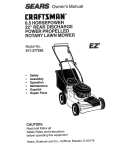
CRI:IFTSMI:IN
OWNER'S
ANUAL
6.6 HORSEPOWER
22" REAR DISCHARGE
POWER PROPELLED
ROTARY LAWN MOWER
Each lawn mower has its own model number.
gine has its own model number.
MODEL NO.
917.377301
Each en-
The model number for your lawn mower will be found on a
decai attached to the rear of the lawn mower housing.
The model number for your engine wil! be found on the
blower housing of the engine,
All parts listed herein may be ordered from any Sears,
Roebuck and Co. Service Center/Department and most
Retail Stores.
WHEN ORDERING REPAIR PARTS, ALWAYS GIVE THE
FOLLOWING INFORMATION:
IFYOU NEED
REPAIR SERVICE
OR PARTS:
* PRODUCT-
LAWN MOWER
* MODEL NUMBER - 917.377301
* ENGINE MODEL NO. - 143.976600
FOR REPAIR SERVICE, CALL
THIS TOLL FREE NUMBER:
1-800-4-REPAIR
(1=800-473-7247)
FOR REPLACEMENT PARTS
INFORMATION AND
ORDERING, CALL THIS
TOLL FREE NUMBER:
o PART NUMBER
= PART DESCRIPTION
Your Sears merchandise has added value when you
consider Sears has service units nationwide staffed with
Sears trained technicians..,
professional
technicians
specifically trained to insure that we meet our pledge to
you, we service what we sell.
! -800-FON-PART
(1-800-366-7278)
3O