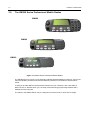
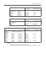
1
Professional Radio
GM300 Series
Selling Guide
68P64114B38
Issue: July 2000
ii
Computer Software Copyrights
The Motorola products described in this manual may include copyrighted Motorola computer programs stored
in semiconductor memories or other media. Laws in the United States and other countries preserve for Motorola certain exclusive rights for copyrighted computer programs, including the exclusive right to copy or reproduce in any form, the copyrighted computer program. Accordingly, any copyrighted Motorola computer
programs contained in the Motorola products described in this manual may not be copied or reproduced in
any manner without the express written permission of Motorola. Furthermore, the purchase of Motorola products shall not be deemed to grant, either directly or by implication, estoppel or otherwise, any license under
the copyrights, patents or patent applications of Motorola, except for the normal non-exclusive royalty-free
license to use that arises by operation of law in the sale of a product.
iii
Table of Contents
Chapter 1
PRODUCT OVERVIEW
1.0 Introduction.......................................................................................................... 1-1
1.1 How to use this Selling Guide ........................................................................ 1-1
2.0 The GM Series of Professional Radios ............................................................... 1-2
2.1 A Common Design Approach......................................................................... 1-2
2.2 Radio Software Upgrades .............................................................................. 1-3
2.3 Quality Assurance .......................................................................................... 1-3
3.0 The GM300 Series Professional Mobile Radios .................................................. 1-4
3.1 GM340 Mobile Radio ..................................................................................... 1-5
3.2 GM360 Mobile Radio ..................................................................................... 1-6
3.3 GM380 Mobile Radio ..................................................................................... 1-7
3.4 Radio Comparison ......................................................................................... 1-8
3.5 Reasons To Trade Up.................................................................................... 1-9
3.6 Radio Sales Models ..................................................................................... 1-10
3.7 Packaged Sales Models............................................................................... 1-10
3.8 Customer User Guides................................................................................. 1-11
3.9 Accessories.................................................................................................. 1-12
Chapter 2
FEATURES AND BENEFITS
1.0 Introduction.......................................................................................................... 2-1
2.0 Audio Quality Enhancement ................................................................................ 2-1
2.1 Xpand™ Voice Compression ......................................................................... 2-1
3.0 Channels ............................................................................................................. 2-2
3.1 Number of channels ....................................................................................... 2-2
3.2 Channel Alias ................................................................................................. 2-2
3.3 Channel Selection .......................................................................................... 2-2
3.4 Memory Channel............................................................................................ 2-3
3.5 Repeater/Talkaround ..................................................................................... 2-3
3.6 Dual Power Levels ......................................................................................... 2-4
4.0 Features .............................................................................................................. 2-4
4.1 Programmable Buttons .................................................................................. 2-4
4.2 Default Settings.............................................................................................. 2-6
4.3 Address, Status and Channel Entry (GM360, GM380) .................................. 2-6
4.4 Power Up Channel ......................................................................................... 2-7
4.5 Power Up Logic.............................................................................................. 2-7
4.6 Power Off Logic.............................................................................................. 2-7
4.7 Power Off Memory ......................................................................................... 2-9
4.8 VOX................................................................................................................ 2-9
iv
5.0 Scan Operation ..................................................................................................2-10
5.1 Scanning.......................................................................................................2-10
5.2 Nuisance Channel Delete .............................................................................2-12
5.3 Carrier Squelch Scan....................................................................................2-12
5.4 Scan Vote .....................................................................................................2-12
6.0 Transmit Features ..............................................................................................2-12
6.1 Transmit Time-Out Timer (TOT) ...................................................................2-12
6.2 Transmit Admit Criteria .................................................................................2-13
7.0 Squelch Features ...............................................................................................2-15
7.1 Receive Squelch Mode.................................................................................2-15
7.2 PL/DPL Squelch Codes ................................................................................2-15
7.3 Monitor..........................................................................................................2-16
7.4 Hook Operation.............................................................................................2-17
8.0 Accessory Connector .........................................................................................2-18
8.1 Dealer Programmable I/O Features..............................................................2-18
8.2 Output Functions ..........................................................................................2-20
8.3 Input Functions .............................................................................................2-22
8.4 Data Transmissions ......................................................................................2-24
8.5 Accessory Packages ....................................................................................2-24
9.0 5 Tone (Select 5) Signalling ...............................................................................2-25
9.1 Introduction ...................................................................................................2-25
9.2 Signalling Standards.....................................................................................2-25
9.3 G/R Tone Redefinition ..................................................................................2-25
9.4 Single Tones.................................................................................................2-26
10.0 5 Tone (Select 5) Encode Sequences ...............................................................2-26
10.1 Telegrams.....................................................................................................2-26
10.2 Contact List (GM360, GM380)......................................................................2-27
10.3 Status Lists (GM360, GM380) ......................................................................2-27
10.4 Address and Status Multicall (GM360 with SMART mic, GM380) ................2-27
10.5 Dedicated Call Buttons (Call 1,2,3 and 4).....................................................2-28
10.6 Telegram on PTT..........................................................................................2-28
10.7 Side Tones On/Off ........................................................................................2-29
11.0 DTMF .................................................................................................................2-29
11.1 DTMF encode sequence ..............................................................................2-29
11.2 DTMF Live Dial Mode (GM360 with SMART mic, GM380) ..........................2-30
12.0 5 Tone (Select 5) Decoder .................................................................................2-30
12.1 Multiple Parallel Decoders ............................................................................2-30
12.2 Individual Calls..............................................................................................2-30
12.3 Group Calls...................................................................................................2-31
12.4 ID Decode Display - Caller Identity (GM360, GM380) ..................................2-31
12.5 Status Decode Display (GM360, GM380) ....................................................2-32
12.6 Call Reminder ...............................................................................................2-32
12.7 Call Back.......................................................................................................2-32
12.8 Missed Calls List (GM360, GM380) ..............................................................2-32
v
13.0 Additional Decode Functions............................................................................. 2-34
13.1 Start Auto-Reset and Stop Auto-Reset (Cleardown).................................... 2-34
13.2 Authorisation ................................................................................................ 2-34
13.3 Stun / Unstun ............................................................................................... 2-35
13.4 Auto-Acknowledge Features ........................................................................ 2-35
13.5 Call Forward................................................................................................. 2-36
13.6 Emergency Calls .......................................................................................... 2-36
13.7 Lone Worker................................................................................................. 2-38
14.0 Option Board Support........................................................................................ 2-39
14.1 Voice Recorder ............................................................................................ 2-39
15.0 User Indications................................................................................................. 2-40
15.1 Display (GM360, GM380) ............................................................................ 2-40
15.2 Menu and Prompts (GM360/GM380)........................................................... 2-40
15.3 Keypad (GM360 with SMART mic, GM380) ................................................ 2-41
15.4 Backlight (GM360, GM380).......................................................................... 2-41
15.5 Alerts ............................................................................................................ 2-41
16.0 Installation ......................................................................................................... 2-42
16.1 Control Heads .............................................................................................. 2-42
16.2 Remote Mount.............................................................................................. 2-42
17.0 Other Dealer Benefits ........................................................................................ 2-43
17.1 Password Protection of the Codeplug .......................................................... 2-43
18.0 Radio Feature Comparisons.............................................................................. 2-44
18.1 GM340/GM360/GM380 vs GP300 Series vs GM950 .................................. 2-44
vi
Chapter 1
PRODUCT OVERVIEW
1.0
Introduction
This Selling Guide is intended to be a reference manual to help you sell and support the GM300
Series Professional Mobile Radios.
This Selling Guide will allow you to answer the following questions:
What product ranges are in the GM Series of Professional Radios ?
What products are in the GM300 Series ?
Who can benefit from the GM300 Series ?
What are the product features ?
How do these features benefit my business ?
This Selling Guide complements the GM300 Series sales training and should be used in conjunction
with a radio on a live system. This hands on experience will provide you with valuable knowledge
which will help you explain the benefits of the GM300 Series to your customers.
1.1
How to use this Selling Guide
The Selling Guide is divided into two chapters Chapter 1 This chapter is a general Product Overview of the New GM Series of Professional
Radios with a more detailed description of the GM300 Series. The chapter provides model numbers
and a list of accessories.
Chapter 2 This chapter describes the Features and Benefits of the product and develops
some ideas on how these features can be of benefit to your customers. The chapter explains the full
flexibility of the radio whilst showing you how simple and easy it is to use.
1-2
2.0
PRODUCT OVERVIEW
The GM Series of Professional Radios
Following the completion of extensive research with you our channel partners and your customers,
Motorola have developed the GM Series of Professional Mobile Radios.
These new radios have been specially developed to meet the communication needs of you and your
customers.
The GM Series consists of three different product ranges :
GM100 Series
A popular and versatile Mobile product range which offers PL and MDC signalling.
GM300 Series
A popular, versatile and sophisticated conventional Mobile product range which offers PL and 5
Tone Selective signalling.
GM600 Series
A popular and versatile trunking Mobile product range which offers MPT1327 signalling.
GM1200 Series
A sophisticated trunked Mobile product range offering MPT1327 trunking signalling.
For further information on GM100, GM600 and GM1200 Series radios, please refer to the relevant
Product Manuals which are listed in your Price Pages.
2.1
A Common Design Approach
All the radios in the GM Series share a common design, the latest RF and semiconductor
technology has been used to produce wideband and fully synthesised radios that offer :
High quality audio allowing effective and efficient communication.
Innovative remote mount design for ease of installation.
Motorola reknowned build quality.
Wide area coverage providing successful communication over a larger
range.
All the radios share a common appearance, common accessories and similar user interfaces.
Common accessories means all GM Series accessories will work with all
GM Series radios - a considerable benefit for you and your customers.
A common user interface means, wherever possible, the radios work in the
same way. This should mean that it will be easier for you and your customers
to learn how to use the radios.
The GM Series of Professional Radios
1-3
Common 5 Tone Mobile and Portable radio user interface.
2.2
The mobile and portable radios share a common CPS and user interface.
This will make it easier for you and your customers to move between radio
platforms.
Radio Software Upgrades
Motorola realise that as communication requirements for you and your customers evolve, it is
necessary to be able to offer a communication solution to meet these changing requirements which
does not force you or your customers to replace existing radios.
Radio software upgrade tools will be available to allow new functionality to be added quickly and
easily to most GM Series radios.
Benefits
You, our channel partners, can upgrade your stock quickly and efficiently.
End users can benefit from new functionality without the cost and inconvenience of buying
new radios.
This will provide you with the ability to offer a changing range of radio benefits to respond to
the evolving needs of your customers.
2.3
Quality Assurance
2.3.1
Accelerated Life Testing
Each model in the GM Series has passed the Motorola Accelerated Life Test (ALT). This testing
simulates 5 years hard use in the field and all Motorola radios pass this rigorous test.
2.3.2
Environmental Protection
All GM Series radios have been designed and tested by Motorola to meet the European standard
specification IP54 and US Military specifications 810 C, D and E.
2.3.3
IP54
This standard demonstrates the radio's ability to withstand driving rain and dust directed at the radio
from all directions.
2.3.4
Military Standards 810 C, D and E
These Military standards ensure efficient radio operation in rough environments. All radios meet the
following specifications :
Low pressure
Salt fog
High temperature
Dust
Rain
Vibration
Humidity
Shock
1-4
PRODUCT OVERVIEW
3.0
The GM300 Series Professional Mobile Radios
GM380
GM360
GM340
Figure 1-1 GM300 Series Professional Mobile Radios.
The GM300 Series is a range of conventional Professional Mobile Radios providing PL and 5 Tone
selective signalling. Research showed that different professions have different communication
needs.
To help you provide different communication solutions for your customers, each radio offers a
distinct choice of features which you can easily customise using programming software and a
suitable personal computer.
The radios in the GM300 Series can be configured to provide on-site or local area coverage.
The GM300 Series Professional Mobile Radios
3.1
1-5
GM340 Mobile Radio
On/Off/Volume
Knob
Programmable
Button 2 (P2)
(Interchangeable)
Red/Yellow/Green
LED Indicators
Programmable
Button 1 (P1)
(Interchangeable)
Microphone
Jack
Channel Indicator LEDs (4)
Channel Selector
Buttons (1, 2, 3 & 4)
MAEPF-26781-O
Figure 1-2 GM340 Radio Features.
This entry level, 2 way radio is easy to use, offering simple functionality with uncompromised
reliability and ruggedness. It has the capability to be fitted with option boards that allow additional
functionality to be added quickly and easily.
Who is the target audience for this radio ?
The GM340 is the affordable communication solution for
professionals who may require a simple, yet flexible, radio and need
up to six different communication channels.
1-6
3.2
PRODUCT OVERVIEW
GM360 Mobile Radio
Exit Button
Menu/Select Button
Red/Yellow/Green
LED Indicators
On/Off/Volume
Knob
Display (1 line 14 characters)
Microphone
Jack
Programmable
Buttons P1 and P2
(Interchangeable)
Channel Selector
or Menu Navigation
Up/Down/Left/Right
Programmable
Buttons P3 and P4
(Interchangeable)
Figure 1-3 GM360 Radio Features
As well as offering all the advantages of the GM340, this versatile radio provides the user with extra
visual information which promotes effective and efficient communication.
Who is the target audience for this radio ?
The GM360 is the ideal communication solution for professionals who
require an informative versatile radio, which offers an increased choice
of communications methods all of which are easily accessible and
simple to use.
Ideal for those professionals who work in large teams and need up to
255 different communication channels.
The GM300 Series Professional Mobile Radios
3.3
1-7
GM380 Mobile Radio
Red/Yellow/Green
LED Indicators
Exit Button
Menu/Select Button
Display (4 lines of 14 characters)
On/Off/Volume
Knob
Keypad
Microphone
Jack
Programmable
Buttons P1 and P2
(Interchangeable)
Channel Selector
Menu Navigation
Up/Down Left/right
Programmable
Buttons F1, F2 and F3
Programmable
Buttons P3 and P4
(Interchangeable)
Figure 1-4 GM380 Radio Features
As well as offering all the advantages of the GM360, this truly sophisicated radio provides the user
with a keypad which allows communication with colleagues other than those who are programmed
into the radio. It also offers a 4-line display for extra user information.
Who is the target audience for this radio ?
The GM380 is the ideal management communication solution, which
with its increased utility further improves efficient and effective
operation.
Like the GM360, this radio is ideal for those professionals who work in
large teams and need up to 255 different communication channels.
1-8
3.4
PRODUCT OVERVIEW
Radio Comparison
The GM300 Series of Professional Mobile Radios share a common design, the differences are
summarised below :
Table 1-1 GM300 Series Professional Mobile Radios Comparison.
GM340
GM360
GM380
On-off / volume control
√
√
√
Channel control
√
√
√
Red, yellow, green LEDs
√
√
√
5 Tone signalling
√
√
√
Option boards
√
√
√
Radio Upgrades
√
√
√
14 Character alphanumeric display
−
1 Line
4 Line
√
√
Menu keys
Keypad with 0 - 9, * and #
−
−
√
Programmable buttons P1, P2,
√
√
√
External Alarm
√
√
√
Channel Steering
√
√
√
Programmable Buttons P1, P2,1-4
√
−
−
Programmable Buttons P1 - P4
−
√
√
Programmable Function Keys F1-F3
−
−
√
External Hook
√
√
√
Display Backlight Control
−
√
√
The GM300 Series Professional Mobile Radios
3.5
Reasons To Trade Up
GM380
All the advantages of the GM360 plus:
Increased number of possible communication contacts using
numeric keypad as well as pre-programmed call lists.
Additional programmable buttons.
4-line display.
GM360
All the advantages of the GM340 plus:
Helpful visual operational information - Includes Current Power
setting, Contact Names and Status Text messages.
Translated Menu Prompts.
Additional feature capability accessible via easy to use dealer
configurable menus including pre-programmed call lists.
255 Communication channels.
GM340
Entry level Professional Radio.
Build quality and environmental specifications.
Simple talk and listen operation with benefits of 5 Tone Selective
signalling.
Radio can be upgraded.
Option board capability.
Special emergency button.
General Purpose input/output (GPIO).
Programmable buttons - more features at your fingertips.
Up to 6 communication channels.
1-9
1-10
3.6
PRODUCT OVERVIEW
Radio Sales Models
The following sales models are available:
Table 1-2 Radio Sales Models.
Model
Description
Frequency
Band
Frequency Range
Power
Level
Model Number
GM340
VHF
136 -174 MHz
1-25W
MDM25KHC9AN1_E
GM340
UHF
403 - 470 MHz
1-25W
MDM25RHC9AN1_E
GM360
VHF
136 -174 MHz
1-25W
MDM25KHF9AN5_E
GM360
UHF
403 - 470 MHz
1-25W
MDM25RHF9AN5_E
GM360
LB1
29.7-36.0 MHz
25-60W
MDM25BKF9AN5_E
GM360
LB2
36.0-42.0 MHz
25-60W
MDM25CKF9AN5_E
GM360
LB3
42.0-50.0 MHz
25-60W
MDM25DKF9AN5_E
GM380
VHF
136 -174 MHz
1-25W
MDM25KHN9AN8_E
GM380
UHF
403 - 470 MHz
1-25W
MDM25RHN9AN8_E
Benefits
Wideband operation and programmable channel spacing means a significant reduction in the
number of different sales models that you need to stock.
Not all the product variants are available in every country due to differences in the local market
requirements. Please refer to your price pages for a complete list of models.
3.7
Packaged Sales Models
All GM340, GM360 and GM380 packaged sales models consist of the following items :
Radio
Basic User Guide
Enhanced Compact Microphone
Power Cable
Low Profile Trunnion
External Loudspeaker (GM380 models only)
Options are available, please check your Price Pages for details.
The GM300 Series Professional Mobile Radios
3.8
1-11
Customer User Guides
In order to help you and your customers use the radios safely and efficiently, two different customer
booklets have been written :
3.8.1
Basic User Guide
Feature User Guide
Basic User Guide
The Basic User Guide provides useful information for your customers on how to start using their new
GM300 Series radio. A copy of this multi-lingual booklet is included in every sales model box.
It contains essential radio safety and care information.
IMPORTANT:
3.8.2
It is important that your customers read and understand this
information. Please ensure your customers receive this booklet
when they receive their radio.
Feature User Guide
The Product Manual contains a printed copy of the Feature User Guide. It has been written
especially for your customers and provides step by step operational instructions for all the features
available for the GM340, GM360 and GM380 radios.
IMPORTANT:
3.8.3
For simplicity, please provide just the operational information for
the features which you have programmed into your customers
radio.
Languages
The Basic User Guide is in the following languages:
English
Spanish
Dutch
Polish
German
Portuguese
Russian
Romanian
French
Danish
Czech
Italian
Swedish
Hungarian
Turkish
The Feature User Guide is in the Product Manual Languages:
English
Spanish
German
French
Italian
Russian
1-12
PRODUCT OVERVIEW
3.9
Accessories
3.9.1
Palm Microphone
The mobile packages include a high performance microphone and hang-up clip. These
microphones offer a Push To Talk (PTT) key and have a “Hang-up switch” at the rear that will clear a
call when the microphone is replaced into the hang-up clip.
A telephone type connector inserts into the radio’s front panel. This connection is protected by a
snug fitting rubber boot designed to keep the connections free from dirt and moisture.
The microphone has been designed for maximum durability. It contains impermeable silicon treated
membranes which eliminate corrosion problems caused by moisture. It also has a sealed
microphone switch to protect against corrosion.
3.9.2
Remote Mount Kit
A remote mount kit is available as an accessory, allowing the control head to be mounted on the
dashboard, whilst the radio unit is situated elsewhere, for example, in the car boot (trunk). This
provides convenient mounting in areas of restricted space, and also reduces the probability of the
mobile radio being stolen.
3.9.3
External Speakers
External speakers are available to provide either 7.5 W or 13 W of audio, enough for clear
communication in even very noisy and harsh environments. The speakers measure approximately
125mm x 125mm x 44mm.
3.9.4
Mounting Bracket and Power Cables
The mobile radio is supplied ready for installation with a rugged swivel mounting cradle and fused 3
metre power cable included as part of the standard packaged model.
3.9.5
Additional Accessories
A wide selection of accessories are available for the mobile radio, which includes a range of
microphones, mounting kits and cables:-
Enhanced Compact Microphone
Heavy Duty Microphone
Smart Microphone ( Enhanced Keypad Microphone)
Visor Mounted Microphone
Telephone Style Handset
Range of Mounting Options
Footswitch With Remote PTT
External Alarm Relay
Power and Control Cable Options
Desk Microphone for use with Base Station
Service accessories
Chapter 2
FEATURES AND BENEFITS
1.0
Introduction
This chapter describes those radio features and functionality which offer a significant benefit to your
customers. The intention is to provide you with useful information which is relevant to your
customers that will help you sell the GM300 Series Professional Mobile radios.
2.0
Audio Quality Enhancement
2.1
Xpand™ Voice Compression
Xpand™voice compression combines two audio quality enhancement features - Companding and
Low Level Expansion (LLE).
2.1.1
Companding
Companding is a collective term to define compressing the audio signal on transmission and
expanding the audio signal on reception. The overall effect is to reduce noise in the received signal,
giving you crisper, clearer audio clarity. Companding should only be used when other radios in your
system have the same companding feature available.
Companding and LLE are mutually exclusive, switching on one of the features automatically
switches off the other.
It is important to ensure that all radios in a team have the feature switched on.
Benefits
2.1.2
Crystal clear communication which makes listening easier.
Improves efficiency as messages are heard and understood first time.
Low Level Expansion (LLE)
This allows improvements in audio quality by reducing noise usually heard during pauses in
conversation.
This feature is automatically included in every radio and should only be switched off in specialised
applications.
Benefits
Pauses in conversations are now silent which makes it easier to listen.
2-2
FEATURES AND BENEFITS
Audio Quality Enhancement Summary
Table 2-1 Xpand™ Summary
LLE
ON
ON
COMPANDING
OFF
3.0
Channels
3.1
Number of channels
OFF
X
(Can’t happen condition)
Recommended for
teams where all radios
use companding
Default factory setting.
Recommended for mixed
fleets of companding and
non- companding radios
Recommended only for
applications where flat
audio is used e.g. data
applications.
The GM340 mobile supports up to 6 channels, the GM360 and GM380 mobiles up to 255 channels.
On the GM340 the channels must be assigned to the 6 programmable buttons. Thus, the number of
buttons left to assign to features is 6 minus the number of channels.
Each channel can be either a repeater channel, where the transmit and receive frequencies differ
(Semi-Duplex operation), or a Talkaround channel, where the transmit and receive frequencies are
the same (Simplex Operation).
3.2
Channel Alias
With up to 255 channels it can be difficult to remember who is on which channel number. To make it
easier to recognise the channels, each channel can be given a meaningful alphanumeric name (or
Alias) up to 14 characters long.
Benefits
3.3
Meaningful names can be given to each channel, making it easier to find the right channel.
Channel Selection
On the GM340, channels are selected by pressing pre programmed buttons; one channel per
button.
Channels
2-3
On the GM360 and GM380 there are several methods to change channel:
Use the up / down scroll buttons. If the buttons are held down, the radio will fast scroll
through the channels.
Enter the channel number directly on the keypad on the GM380, or on the SMART mic on
the GM360.
Press a Memory Channel button.
With direct entry from the keypad, the menu select button (tick) must be pressed before the radio
goes to the new channel. If the selected channel is invalid (including wrong number of digits), an
error tone is sounded, and the radio returns to the Channel menu option.
Benefits
3.4
Different methods of channel selection to suit the user.
Fast scroll, direct keypad entry and Memory Channel all facilitate fast channel selection.
Memory Channel
On the GM360 and GM380, up to two of the programmable function buttons can be programmed as
Memory Channel. A Memory Channel button has a specific channel assigned to it. A short press of
the button will take the radio direct to that channel without having to use the channel scroll buttons or
keypad.
Memory Channel buttons avoid the hassle of scrolling through all the channels programmed into the
radio; they jump straight to a predefined channel.
Memory Channel buttons can be fixed or user programmable. If the Memory Channel buttons are
user programmable, a long press of the button changes the channel assigned to the button to the
one that radio is on at the time. This allows the user to redefine the channels if a particular channel
is more frequently used.
User programmed Memory Channels are remembered when the radio is turned off.
Benefits
3.5
Fast Access to Important Channels
User Programmable for day to day operations
Repeater/Talkaround
Repeater channels use fixed base equipment to increase the range of the radio's signal. Sometimes
a repeater is used to interface users to telephone interconnect equipment or other system features.
Talkaround frequencies are used between radios within close range of each other when there is no
repeater, the repeater is not operating or communications off a system repeater is desired.
A programmable button can be programmed as a Repeater/Talkaround select. On a Repeater
channel that has “Talkaround” enabled, the programmable button toggles the channel between
repeater and talkaround frequencies.
Benefits
Provides direct (radio-radio) operation.
Allows operation out of repeater range.
Continued communication even when parts of the system are taken out of service for
maintenance.
2-4
3.6
FEATURES AND BENEFITS
Dual Power Levels
Two transmitter power levels are available (high or low) on a radio wide basis. Once the power levels
are set in the CPS, each channel can be configured as a high power or low power channel.
The two levels are easy for the service shop to set up - simply type in the absolute power level
required (e.g.: “5” for 5 watts, or “15” for 15 watts) and the radio automatically provides this power on
the relevant channel. These power levels can be copied from one radio (or archive file) to another
radio, significantly reducing workshop time when selling a large fleet of radios.
The power level on a channel can be toggled via a programmable button or the menu.
Benefits
Power programmable per channel.
Low power reduces air way interference and congestion.
High power allows the radio to transmit over a greater distance.
4.0
Features
4.1
Programmable Buttons
The GM300 Series Professional Series mobiles have CPS programmable buttons. They can be
programmed with a wide range of features that are available in the radio. The most commonly used
features can be programmed to these buttons, thereby customising the radios to the individual
customers’ needs.
The GM340 has 6 programmable buttons. However, channel selection must also be assigned to
these programmable buttons. Thus, the number of buttons left to assign to features is 6 minus the
number of channels
The GM360 has 4 programmable buttons. If the SMART mic is used, the 3 programmable buttons
on that can also be used, giving a total of 7 programmable buttons.
The GM380 has 7 programmable buttons. If the SMART mic is used, the 3 programmable buttons
(A, B and C) are programmed in parallel to the F1, F2 and F3 buttons on the radio.
4.1.1
Exchangeable Buttons
Some of the programmable buttons on the radios are exchangeable. They can be removed and
replaced with buttons showing icons that represent the function programmed to them. This improves
the ease of use for the user as the buttons show representative icons for the programming.
P1 and P2 on the GM340, and P1 to P4 on the GM360 and GM380 are exchangeable.
Benefits
Most frequently used features are available on a button press.
Exchangeable buttons make user identification of programmable buttons very easy.
Features
2-5
Table 2-2 Exchangeable Buttons
Feature
Icon
Channel
Description
Button Type
Direct entry in to Channel menu
Direct entry
Memory Channel 1
M1
Direct entry to Memory Channel 1
Direct entry
Memory Channel 2
M2
Direct entry to Memory Channel 2
Direct entry
S
Direct entry in to Status List menu
Direct entry
Direct entry in to Contact List menu
Direct entry
Direct entry in to Missed Calls menu
Direct entry
Status List
Contact List
GM340 GM360 GM380
Call1
Call 1
Sends out Call 1 telegram
initiate
Call 2
Call 2
Sends out Call 2 telegram
initiate
Call 3
Call 3
Sends out Call 3 telegram
initiate
Call 4
Call 4
Sends out Call 4 telegram
initiate
Call button specific to call
base / dispatcher
initiate
initiate
Missed Calls
Q
Base Call
Emergency
orange Puts radio into Emergency mode
button
DTMF
D
Puts radio into permanent DTMF Live Dial initiate
mode
Monitor/Cancel
C
Toggles radio between Monitor 1 / 2
mode, and normal squelch mode.
toggle
Talkaround
J
Toggles radio between Talkaround and
Repeater operation
toggle
Power level
B
Toggles radio power between high and
low
toggle
Switches Scan feature on/off
toggle
Switches Lone Worker feature on/off
toggle
Switches External Alarm feature on/off
toggle
Switches Call Forward feature on/off
toggle
Scan
G
Lone Worker
External alarm
Call Forward
b
Fwd
Keypad Lock
Locks/Unlocks Keypad and menu buttons toggle
Option Board
N
Switches Option Board feature on/off
Companding
A
toggle
Switches Xpand feature on/off
toggle
Backlight
Switches Backlight on/off
toggle
Play/Record
To Play / Record messages on voice stor- initiate
age option board
initiate
Nuisance Delete
C
Deletes nuisance channel from scan list
Cancel
C
Cancels / deletes messages from Voice initiate
Storage feature
Nuisance Delete /
Cancel
C
Combines Nuisance Delete and Cancel
Personality
P
Data
D
A
initiate
Other Exchangeable Buttons Available
Voice Message
Absent
LLE
Clear/Coded
LLE
L
2-6
4.2
FEATURES AND BENEFITS
Default Settings
The display, up / down buttons and keypad can be programmed to start up in different modes. This
allows the radio to be configured to provide the most user friendly operation.
4.2.1
Default Display Mode (GM360/GM380)
When the display is in the idle state, it displays the default display. This can be programmed to be:
4.2.2
Text up to 14 characters long;
Channel on GM360;
Channel, Status and Address on GM380.
Default Up / Down Button Mode (GM360/GM380)
The default function of the up / down navigation buttons can be programmed to be:
4.2.3
Channel;
Address;
Status.
Default Keypad Mode (GM360 with SMART mic, GM380)
The default function of the keypad can be programmed to be:
Channel;
Address;
Status.
Benefits
4.3
Default settings allow the most frequently used function(s) to be programmed to up / down
and/or keypad, thus customising the radio for optimum performance. This saves the radio
user’s time.
Address, Status and Channel Entry (GM360, GM380)
The Address, Status and Channel can be entered immediately on the up /down buttons or the
keypad, if they are set up as the default modes. If they are not the default modes, the Address,
Status and Channel entry menus can be selected through the menu navigation buttons or
programmable buttons programmed to provide direct entry to the appropriate menu.
Once in the entry menu, the selected feature can be:
Incremented or decremented by the up / down menu navigation buttons;
Entered directly on the keypad (GM360 with SMART mic, GM380).
After a period of inactivity (10 seconds) or an item is selected, the radio returns to its default modes.
Benefits
Keypad direct entry of the Address, Status and Channel digits allows fast selection.
Programmable buttons allow rapid change between entry functions.
Both these make the radio quicker to use and save the radio user’s time.
Features
4.4
2-7
Power Up Channel
The radio can be programmed to power up on a pre-defined channel or the last used channel.
Benefits
4.5
Designated Power Up Channel avoids missing first messages
Power Up Logic
The radio can be powered up by:
Pressing the on/off switch;
Asserting the emergency wake up line (GPIO pin 9). If emergency with wake up is enabled
on the radio and an emergency switch is connected to the accessory connector, the radio
automatically turns on in emergency mode whenever the emergency switch is pressed.
Emergency wake up takes priority over the other power up mode.
Asserting the ignition line (GPIO pin 10). If ignition sense is enabled on the radio and the
vehicle’s ignition is connected to the accessory connector, the radio will automatically turn
on whenever the vehicle ignition is turned on;
Benefits
4.6
Ignition power up caters for users where auto power-up is required, for example, Fire Engines.
Power Off Logic
The ability to turn the radio off is dependant on:
Its turn on method
The state of the ignition line
Whether “ignition override” is enabled
Whether it is in emergency mode
Whether “ON/OFF in emergency” is enabled
If the radio is turned ON via the ON/OFF switch, it can only be turned OFF via the ON/OFF switch.
However, if Ignition Override is enabled, the ignition line must be de-asserted (ie the vehicle turned
off) before the radio can be turned off via the ON/OFF switch.
If the radio is turned ON via the ignition, it can be turned OFF via the ignition or the ON/OFF switch.
However, if Ignition Override is enabled, the radio can only be turned off via the ignition.
If the radio is turned on via the emergency wake up, and ON/OFF in emergency is disabled, the
radio cannot be turned OFF.
If the radio is turned on via the emergency wake up, and ON/OFF in emergency is enabled, the
radio will follow the turn OFF rules as if it had been turned ON via the ON/OFF switch.
The Power OFF logic is shown in the tables below:
2-8
FEATURES AND BENEFITS
Radio turned ON via ON/OFF button
Possible Actions
Press ON/OFF
Start State
Ignition Override
Ignition line
Disabled
Asserted
Disabled
Enabled
Enabled
De-assert Ignition Line
Effect on radio
Switch OFF
Stay ON
Not asserted
Switch OFF
-
Asserted
Stay ON
Stay ON
Not Asserted
Switch OFF
-
Radio turned ON via Ignition
Possible Actions
Press ON/OFF
Start State
De-assert Ignition Line
Effect on radio
Ignition Override
Disabled
Switch OFF
Switch OFF
Enabled
Stay ON
Switch OFF
Radio turned ON via Emergency
Possible Actions
Press ON/OFF
Start State
De-assert Ignition Line
Effect on radio
ON/OFF in
Emergency
Ignition Override Ignition line
Disabled
Disabled
Asserted
Stay ON
Stay ON
Disabled
Disabled
Not asserted
Stay ON
-
Disabled
Enabled
Asserted
Stay ON
Stay ON
Disabled
Enabled
Not Asserted
Stay ON
-
Enabled
Disabled
Asserted
Switch OFF
Stay ON
Enabled
Disabled
Not asserted
Switch OFF
-
Enabled
Enabled
Asserted
Stay ON
Stay ON
Enabled
Enabled
Not Asserted
Switch OFF
-
Benefits
The radio can only be turned OFF in specified conditions.
ON/OFF in Emergency prevents the radio from being turned OFF by mistake or by attacker.
Features
4.7
2-9
Power Off Memory
Certain features are remembered when the radio is turned off, and reinstated when the radio is
turned on.
Channel - (unless there is a designated power up channel)
Last selected Address
Last selected Status
Last stored Memory Channel
Backlight ON/OFF
Keypad Tones ON/OFF
Keypad lock ON/OFF
Escalert ON/OFF
Voice messages
Stun state
Benefits
4.8
Operational Parameters are not lost when the radio is turned off.
VOX
Whenever the user speaks into the microphone the radio automatically goes into transmit mode; this
is the equivalent of pressing the PTT.
With various audio threshold levels and tolerances programmed into the radio, the VOX feature
intelligently senses background noise, resulting in VOX adapting automatically to the noise level in
the environment by setting the microphone input to key up the radio.
The microphone sensitivity can be adjusted to take account of the background noise.
VOX operation is only possible when a special VOX accessory is fitted to the accessory connector of
the mobile.
Benefits
"Hands free" radio operation.
Drivers can talk without having to take their hand off the steering wheel, or look away from the
road.
Passengers do not have to stop, put down their work tools and pick up the radio when making
and receiving a call - this increases productivity.
VOX operation automatically adapts to any noise level.
2-10
FEATURES AND BENEFITS
5.0
Scan Operation
5.1
Scanning
Scanning allows activity on different communication channels to be monitored. Each radio can be
programmed with up to 32 scan lists, and each scan list can contain up to sixteen channels which
are listened to sequentially.
Once scan has started, detection of an incoming call causes the radio to automatically switch to the
channel so that the call can be received and scan temporarily stops: this is called the “landed” state.
Benefits
5.1.1
Efficient communication - incoming calls are not missed even when they can be received from
more than one communication channel.
Simplifies the radio operation for users of multiple communication channels.
Single Priority Scan
Each list can specify a “Priority” channel that is monitored for activity more often, even when the
radio is “landed” and listening to another channel in the scan list. If the correct unmute condition is
detected on the priority channel when the radio has ‘landed on’ another channel, the priority alert
will sound and it will switch to the priority channel to take the call.
5.1.2
Scan Activation
Each channel can be programmed to use any of the scan lists. Scan is activated by:
5.1.3
pressing a programmable button that has been programmed as the Scan button;
selecting scan via the menu;
changing to a channel which has been programmed with “Automatically Start Scan”: this starts scan operation as soon as the radio switches to that channel, i.e. Auto Scan.
Scan Transmit Channel and Talkback
When the radio is not in the landed state (i.e. it is actively scanning, looking for valid channel
activity), pressing the PTT causes the radio to change to the defined “Scan Transmit Channel”,
where it remains for the duration of the two-way conversation, after which active scanning resumes.
The Scan Transmit Channel choices are:
Scan Start Channel
Designated Channel
Last Free Channel
Last Busy Channel
Voted Channel
“Talkback” mode allows the user to respond directly to messages received on “landed” channels, as
long as the response begins during the programmable scan hang timer (called the listen “Scan
Reset” Timer). If Talkback is disabled, pressing the PTT when in the landed state causes the radio
to change to the defined “Scan Transmit Channel”. Talkback has no impact when the radio is
actively scanning - it only has an impact on the radio’s operation in the landed state.
Scan Operation
2-11
Scan Start Channel (home channel):
Causes the transmission to occur on the original channel that the radio was on, when scan
operation was started. Talkback can be enabled or disabled.
Designated Channel:
Causes transmissions to occur on a designated, pre-programmed channel. Again Talkback can be
enabled or disabled.
Last Busy Channel:
Causes transmissions to occur on the channel that was the most recently “landed” on (i.e.: busy).
Talkback can be enabled or disabled.
Last Free Channel:
Causes transmissions to occur on the channel that was most recently detected as being free of
activity. The last free channel is updated each time the scan list is gone through, to ensure that the
last free channel remembered by the radio was very recently free. When the PTT is pressed this
avoids, as far as possible, sending the radio to a channel that is now busy. Talkback can be enabled
or disabled.
Voted Channel:
Causes transmissions to occur on the last voted channel. See the section on Scan Vote.
Scan TX
Mode
Channel to transmit on, or to suspend scan on, if taken off-hook
During Active
Scan
Landed,
Talkback disabled
Landed,
Talkback enabled
Scan Start
Channel
Home
Home
Landed
Designated
Designated
Designated
Landed
Last Busy
Last Landed
Landed
Landed
Last Free
Last Free or
invalid if none
Landed
Landed
Voted
Voted
Voted
Landed
The radio’s display indicates the channel on which transmission will occur or is occurring, depending
on the operational mode in use.
NOTE In order to have the radio “power-up” into scan mode, the power-up channel should
be defined, and be set to an “Auto Scan Start” channel.
Benefits
Calls can be initiated even whilst scanning.
Auto Scan simplifies scan operation, and frees up a function button.
Highly flexible - tailor to match specific user requirements.
The most important channel can be scanned more frequently than other channels and even
when landed on another channel.
2-12
5.2
FEATURES AND BENEFITS
Nuisance Channel Delete
Nuisance Channel Delete allows channels which continually generate unwanted calls or noise to be
temporarily removed from the scan list. The priority channel, last channel in the scan list and home
channel cannot be deleted.
A programmable button must be set up as nuisance channel delete. Deleted channels can be
recovered by turning the radio or scan off and back on again.
Benefits
5.3
Nuisance Channels can be temporarily removed from the scan list by the user.
Efficient radio operation as the radio just listens to channels where valid calls will be received.
Carrier Squelch Scan
Carrier Squelch Scan allows the user to hear all activity on the scan list channels; the radio does not
check PL/DPL or tone signalling. Scanning just for carrier is the fastest scan method.
5.4
Scan Vote
Scan Vote mode is used in multi-frequency simulcast systems that provide wide area repeater
coverage in applications where frequency spectrum is readily available. The typical system has a
set of scattered base sites that are transmitting the same information on different frequencies. The
radios scan the frequencies of these base sites and perform a voting algorithm to select the
strongest base site. The radio’s transmit frequency is typically the same on every channel, but the
radio’s receive frequencies are different.
The voting algorithm is described in the CPS help text.
6.0
Transmit Features
6.1
Transmit Time-Out Timer (TOT)
The Transmit Time Out Timer limits the duration of calls by cutting off transmission after a
pre-programmed time.
TOT can be implemented in order to enforce efficient use of air time. Also in vehicular operations, a
microphone can accidentally be lodged between seats or other objects and accidentally become
continuously keyed. This would deny other users from using the channel. TOT automatically ends
the call and frees up the channel.
The TOT can be
non-cumulative: the TOT returns to zero each time the radio is de-keyed;
cumulative: the TOT adds all transmission times since the call started. The TOT returns
to zero when the call ends (auto reset timer expires or is cancelled).
A “TOT Pre-Alert” can be programmed to sound five seconds before the transmission is cut off, to
warn the user to finish the conversation.
Transmit Features
2-13
A “Re-Key inhibit duration” can be programmed, which prevents users from re-transmitting a
period of time after the TOT has expired. This prevents an individual user from “hogging” the
channel.
A “De-Key Telegram on TOT” can be programmed to send a telegram when the radio times out.
Benefits
6.2
Enforces efficient use of airtime.
Addresses accidental continuous keying.
Re-Key Timer stops users hogging the channel.
Transmit Admit Criteria
Transmit Admit Criteria automatically check the channel for activity and only allow the radio to
transmit if certain criteria are met. This enforces radio operational discipline and simplifies radio
operation. The Transmit Admit Criteria available are:
Never Allowed - This option prevents the user transmitting and operationally the channel is receive
only.
Always Allowed - This option allows the user to transmit at any time.
Channel Free - This option only allows transmission when carrier is not present.
PL/DPL Lockout - This option only allows transmission when carrier is not present, or
when carrier is present and the radio is detecting the PL decode frequency for the channel.
This option is required for the type of repeater that holds up both carrier and PL during repeater
hang time. Repeater hang time is the period of time during which the repeater remains keyed after a
user’s radio has de-keyed. It is used to prevent other users with different PLs gaining access and
control of the repeater before a ‘called’ radio with the same PL has had a chance to reply.
Past PL/DPL Lockout - This option only allows transmission when carrier is not present, or
when carrier is present and the radio has detected the PL decode frequency for the channel since
carrier was detected.
NOTE Carrier is assumed to be lost when the radio is keyed, so this criterion must be
satisfied again after de-key.
This option is required for the type of repeater that only holds up carrier (not PL) during hang time,
but where the radios on the repeater use PL. It is used to prevent other users with different PLs
gaining access and control of the repeater during gaps in the conversation.
In this case the called radio, not receiving PL during the hang time, must remember that it did
receive the correct PL prior to hang time and is therefore able to transmit.
2-14
FEATURES AND BENEFITS
Carrier Gone Timer Expired – This option only allows transmission when carrier has not been
detected for a programmable period of time.
This option is used to prevent operators currently not involved in calls, transmitting over other users
who may be active on the channel, but are de-keyed with their auto-reset timers running.
PL/DPL Not Detected – This option only allows transmissions when carrier is not present, or
when carrier is present and the radio is not currently detecting the PL decode frequency for the
channel.
This option may be used:
To prevent PL users in the same group from transmitting over each other;
If used on repeaters that transmit PL during hang times, users from other groups can gain
access during the repeater hang time.
If one group is monopolising a repeater, it allows another group to ‘break in’ during
repeater hang time if a PL is also transmitted;
Potential problems are:
Should not be used on repeaters that transmit PL during repeater hang time as users
within the same group cannot transmit during this period and this leads to enforced gaps
in the conversation.
A PL user from one group can transmit at the same time as a PL user from another group.
Past PL/DPL Not Detected – This option only allows transmissions when carrier is not present, or
when carrier is present and the radio is not and has not detected the PL decode frequency for the
channel since carrier was detected.
Channel Free or No PL/DPL but Past PL/DPL – This option only allows transmissions when
carrier is not present, or
when carrier is present and the radio is NOT currently detecting the PL decode frequency for the
channel but has detected the PL decode frequency since carrier was detected.
Benefits
6.2.1
Enforces channel discipline.
Prevents improper radio transmissions.
Prevents crosstalk on a shared frequency.
Equal user access when combined with Time Out Timer.
Transmit Admit Criteria not Applied in Auto Reset
It is possible to disable the Transmit Admit Criteria whilst the radio is in Auto Reset.
Benefits
Once a call is set up, the user is always able to transmit during the Auto Reset time, this
means they can always finish their call.
Squelch Features
6.2.2
2-15
Channel Free Beep
If a transmission attempt fails due to Transmit Admit Criteria not being satisfied, a Channel Free
Beep is sounded as soon as the criteria are satisfied.
Benefits
User is advised as soon as they are permitted to transmit; particularly useful on a busy
channel.
Message can be sent as soon as possible.
Don’t have to waste time re-trying to transmit.
7.0
Squelch Features
7.1
Receive Squelch Mode
Squelch settings are used to keep the radio’s loudspeaker turned off unless the required type of
signal is detected. The default squelch mode of the radio when it is first turned on can be set as any
of the following:
7.2
Open Squelch (Hear all background noise)
Carrier Squelch (Only open squelch if Carrier is detected)
PL/DPL Squelch (Only open squelch if the correct PL/DPL is received)
Tone Squelch (Only open if the correct 5 tone signal is received)
Tone & PL/DPL (Only open if correct 5 tone and PL/DPL are received)
PL/DPL Squelch Codes
PL/DPL squelch can be explained to customers as a way to stop them hearing communications
between other users on the same channel who are not in their group (on the same PL/DPL). It
allows several groups within an organisation to share the same channel.
PL codes are often used to access community repeaters.
Each channel can be programmed with separate encode and decode PL/DPL codes.
PL codes can be set between 65 and 255Hz, in 0.1Hz steps.
DPL has 103 codes between 023 and 754.
7.2.1
PL Squelch
PL squelch can be:
Standard: squelch requirements are satisfied when its PL is present
Reverse: squelch requirements are satisfied when its PL is not present
2-16
7.2.2
FEATURES AND BENEFITS
PL Reverse Burst / DPL TOC
A Reverse Burst or Turn Off Code (TOC) can be generated when the PTT is released on a channel
transmitting PL/DPL (respectively). It is sent to indicate the end of transmission to the receiving
radio and so reduce squelch tail.
These are the equivalent of 5 tone Cleardown / Remote Close calls.
Benefits
7.3
Different groups in an organization can share a channel
Users don't hear the communications of other groups
Monitor
Monitor allows the normal Receive Squelch Mode to be temporarily disabled. This allows voice
activity on a channel to be listened to. It is particularly useful in radio systems when a single
communication channel is shared by several different teams of people, as it allows individuals to
check that the channel is free prior to making a call.
NOTE On many community repeaters monitor is not allowed, as users are not allowed to
hear other users’ communications. If this is the case, Transmit Inhibit Criteria can be
used instead.
7.3.1
Monitor 1 and Monitor 2 Modes
The GM300 Series radios have 2 monitor modes; short press for Monitor 1; long press for Monitor 2.
Monitor 1 disables one level of receive squelch, monitor 2 disables a second level of receive
squelch.
For example,
Example 1
Example 2
Standard Receive Squelch
PL
Tone & PL
Monitor 1 Squelch (Short Press)
CSQ
PL
Monitor 2 Squelch (Long Press)
Open
Open
If the radio is in auto-reset mode, ‘tapping’ the monitor button causes auto-reset to end and put the
radio into receive squelch mode: ie it will end a call. A long press will put the radio into monitor 2
mode.
Squelch Features
7.3.2
2-17
Forced Monitor on PTT (Smart PTT)
It is good radio practice to monitor the channel before transmitting. Forced monitor on PTT enforces
this. The first press of the PTT or a call button puts the radio in monitor mode. The second press of
the PTT or call button actually make the radio transmit. This is Forced Monitor ‘Always’.
Forced Monitor ‘Only if Channel Busy’ is a Smart PTT. It only enters monitor mode if there is
channel activity; if there is no channel activity the radio is allowed to transmit on the first PTT or call
button press.
Benefits
7.4
Allows squelch codes to be temporarily disabled.
Forced monitor enforces good radio practice.
Forced monitor is an easy way to monitor channel for activity prior to transmitting.
Encourages users not to transmit over the top of other users.
Hook Operation
Going “Off-Hook” by taking the microphone out of its hang-up clip makes the radio enter auto-reset
mode, which in turn changes the squelch setting to that defined as the autoreset squelch.
The options available for the Hook are all to do with length of time that the hook function is active. It
can be:
Disabled -
(Going Off Hook has no effect);
Permanent - (The function is active for all the time it is Off Hook);
Timed -
(The function is active only for the duration of the AutoResetTimer,
even if the microphone is left Off Hook).
The Hook feature is ignored if the radio is in any of the following modes:
Emergency;
Stunned;
Menu.
Benefits
Easy way to monitor the channel for activity prior to transmitting
Timed Hook automatically squelches the radio, so the user doesn’t have to put the
microphone back on the physical hang up switch.
2-18
FEATURES AND BENEFITS
8.0
Accessory Connector
8.1
Dealer Programmable I/O Features
All models of the GM300 Series Professional mobile radios incorporate a dealer programmable
accessory connector as standard.
There are:
4 input lines,
1 output line, and
3 input / output (I/O) lines.
Table 2-3 Accessory Connector I/O Features
Pin number
3
4
External Output Functions:
PL/DPL Detect
Radio Busy
External Alarm
Per Channel Output
Car Radio Mute
PTT Sense
Decoder Output Control
Channel Steering
Hook
Voice PTT
Data PTT
Voice & Data PTT
Mute Audio PA
Open RX Audio
Public Address
Call 1/2/3/4
Emergency
Emergency Wakeup
Ignition
8
Carrier Detect
External Input Functions:
6
9
10
12
14
GM950
Yes
Yes
Yes
Yes
Yes
Yes
Yes
Yes
Yes
Yes
Yes
Yes
Yes
Yes
Yes
Yes
Yes
Yes
Yes
Yes
Accessory Connector
2-19
Table 2-4 Accessory Connector Pin Out
Function
Pin
1
Speaker -
2
External Mic
3
Digital In 1 (Ext. PTT use External Mic/ Data PTT use Flat TX Audio)
4
Digital Out 2 (External Alarm)
5
Flat TX Audio. Sensitivity 150mV rms to for 60% deviation
6
Digital In 3
7
Ground
8
Digital In/Out 4
9
Digital In 5 with Wakeup (Emergency)
10
Digital In 6 with Wakeup (Ignition)
11
Flat / Filtered RX Audio (Flat RX Audio 330mV rms at 60% deviation
Filtered RX Audio 600mV rms at 60%dev at 1kHz) CPS selectable
12
Digital In/Out 7
13
Switched Battery Voltage (max 1A, Dropout Voltage max1V)
14
Digital In/Out 8
15
RSSI (Radio Signal Strength Indicator)
16
Speaker +
17
Bus+ (used for CPS and Flash)
18
Boot Control
19
Reserved
20
Reserved
Each programmable pin can be disabled or programmed to a feature. The active state of each pin
can be set as high or low: except
emergency is active low;
ignition is active high.
NOTE Please refer to the Radio Installation Manual for more information.
Benefits
Enables interface to a wide range of external devices.
Customer specific applications can be catered for.
Gives excellent opportunities for enhanced dealer added value.
Interface to external Mobile Data Modems.
2-20
FEATURES AND BENEFITS
8.2
Output Functions
8.2.1
Carrier Detect
The output is asserted whenever carrier is detected and is de-asserted if no carrier is present.
The output is de-asserted if the radio is in TX mode.
8.2.2
PL/DPL Detect
The output is asserted whenever the correct PL is detected.
If PL override is disabled, the output is de-asserted when the correct PL is lost.
If PL override is enabled, the output remains asserted for the AutoReset time after the correct PL is
lost. This is particularly useful when the mobile is used as a base station and needs to remain active
during short losses of RF or PL, eg when the signal is lost for a short moment, or a 5 tone sequence
is sent (many earlier radios cannot encode PL and 5 tone simultaneously).
The output is de-asserted if the radio is in TX mode.
8.2.3
Radio Busy
This output is asserted whenever carrier is detected, or the radio is in TX mode.
8.2.4
External Alarm
If the radio has external alarm enabled and a telegram is decoded that has external alarm enable,
the output is asserted. This output can be used to energise a relay, etc, that will sound the car's horn
and, or flash the lights.
The output is de-asserted when any button is pressed, the radio is stunned or the external alarm
timer expires. The timer is reset each time the output is asserted. For instance, if the external alarm
duration is 5 seconds, and two decodes are received 1 second apart, the alarm starts on receipt of
the first decode, and stop 6 seconds later (i.e., 5 seconds after the second decode).
External Alarm cannot be enabled on decoders set for Stun, Ack1 ringing, Ack1 Answer or Silent
Interrogate.
NOTE This feature is not legal in all countries.
Benefits
Enables the radio user to be aware of an incoming call when out of, but near to, the vehicle.
Accessory Connector
8.2.5
2-21
Per Channel Output
The output is asserted when the radio is on a channel that has 'Per Channel Output' enabled,
otherwise the output is de-asserted.
This is used to drive any device which is channel usage specific.
8.2.6
Car Radio Mute
This option is used to mute the audio on a car’s hi-fi system when the two way radio is in use.
The output is asserted if the radio’s loudspeaker is open or the radio is transmitting.
The output is de-asserted if the radio’s loudspeaker has been closed and the radio has not
transmitted during the preceding 5 seconds.
8.2.7
PTT Sense
PTT sense is an output line that follows the internal PTT input line. It is used to give full control of the
transmit function to an external device, eg a computer sending data, so that it can control a user’s
attempts to transmit voice messages.
If PTT sense is programmed, when the internal PTT is pressed, the PTT sense line is asserted.
Note that pressing the mic PTT does not make the radio go into transmit. If the external device is not
transmitting, it asserts the Voice PTT line. It is this that causes the radio to transmit and the audio to
be transmitted.
If the external device is already transmitting, it does not assert the Voice PTT line and the voice will
not be transmitted. When the external device finishes transmitting, it accepts the next internal mic
PTT.
In this application, the audio source must be set to the front microphone, with external voice PTT.
The data source is input on the flat Tx audio line (pin 5), with external data PTT.
If Voice and Data PTT is used (instead of separate Voice PTT and Data PTT), the external device
will not transmit it’s data whilst the audio is transmitting. However, if data is being transmitted, and
the internal PTT is pressed, voice and data will be transmitted simultaneously. This set up will
reduce but not eliminate the possibility of voice and data being transmitted simultaneously, and
hence the data being corrupted.
Benefits
Allows an external device to take control of the transmit function of the radio.
Allows data and audio to be sent from the same radio without clashing.
2-22
8.2.8
FEATURES AND BENEFITS
Decoder Output Control
The output is asserted by the successful decode of a decoder that has 'Assert Output Control'
enabled.
It is de-asserted by the successful decode of a decoder that has 'De-assert Output Control' enabled.
This option is enabled/disabled per personality. This function can be useful for simple telemetry
applications.
Benefits
Allows remote control of external device.
When used in conjunction with external call switch, gives simple telemetry.
8.3
Input Functions
8.3.1
Channel Steering
Channel steering allows an external device to select a channel, using a parallel interface.
The CPS can configure up to 5 input pins in channel steering mode. On the GM340 there are only 3
pins available and six channels selectable.
The radio software takes the state of these inputs and brings them together to form an N bit value,
where N is the number of pins assigned to channel steering by the CPS and the channel selected is
a result of the binary count obtained from these pins; the least significant bit is assigned to the
lowest pin number that has channel steering assigned to it.
This value is the Channel Steering Index.
If the Channel Steering Index is zero, channel steering has no affect and channels are selected by
normal user inputs.
If the Channel Steering Index is not zero, then the channel is set to the channel that corresponds to
the Channel Steering Index value. If the selected channel index refers to a channel higher than the
number of channels programmed in the radio, the highest available channel is selected.
Any attempts to change channel via user button action are ignored if the Channel Steering Index is
not zero, and the Button Error Alert is sounded instead. This includes the following button actions:
Up/Down.
Memory Channel.
Entering channel numbers via the keypad.
If the Channel Steering Index is reset to zero the radio returns to the last ‘user selected’ channel.
If the radio goes into any Emergency Mode for which an Emergency Revert Channel is defined, the
Emergency Revert Channel takes precedence over Channel Steering.
8.3.2
Hook
External hook performs the same function as microphone hook. This can be a mechanical hang-up
or electrical switch.
Accessory Connector
8.3.3
2-23
Voice PTT
If Voice PTT is asserted, the TX audio is routed from one of the microphone paths. CPS
programming defines whether the external voice PTT uses the internal or external (pin 2)
microphone audio path.
8.3.4
Data PTT
If data PTT is asserted, it is assumed that the external PTT is an electronic switch (e.g. a modem)
and that it requires the fastest possible radio response. When this pin is asserted the microphone
path is muted and the TX audio is routed from the Flat TX audio input (pin 5).
8.3.5
Voice & Data PTT
If voice and data PTT is asserted, it is assumed that the external PTT is an electronic switch that
requires the fastest possible radio response. The microphone path and the Flat TX audio input are
both enabled and the two signals are summed to form the TX signal. CPS programming defines
whether the external PTT uses the internal or external (pin 2) microphone audio path.
8.3.6
Mute Audio PA
When this input is asserted the audio PA (and speaker) is muted. When it is de-asserted, the audio
PA operates under normal software control and follow programmed squelch requirements.
8.3.7
Open RX Audio
When this input is asserted the received audio, or option board audio (if fitted), is routed through to
the audio PA (and speaker) independent of the normal squelch criteria.
8.3.8
Public Address Enable
When enabled, this feature allows the radio to act as a ‘Public Address’ system. An external switch
is connected to this pin. When this pin is asserted, the radio routes the internal or external mic audio
through to the Rx Audio (pins 7 and 11). A public address kit must be connected to the Rx audio
pins; this provides extra audio amplification and connection to an external speaker (eg mounted on
the roof of the car).
When the public Address pin is asserted and the mic PTT is pressed, the radio cannot receive calls.
When the Public Address pin is asserted but the mic PTT is not pressed, the radio can receive calls.
However, the Public Address pin must be de-asserted (ie the external Public Address switch moved
to OFF) before the user can reply to the call.
8.3.9
Call 1, Call 2, Call 3, Call 4
If one of call 1, call 2, call 3 or call 4 inputs is asserted, then its associated telegram is transmitted.
It provides the same functionality that is assigned to a call programmed on a button.
2-24
8.3.10
FEATURES AND BENEFITS
Emergency
If an emergency switch is assigned, asserting the input causes the radio to go into emergency
mode.
Emergency switch assigned to pin 9 is a special case. In addition to normal emergency mode,
asserting the input when the radio is turned off will invoke Emergency with Wake Up. This causes
the radio to power up and immediately enter Emergency mode.
8.3.11
Ignition
Ignition sense is programmable per radio. Connecting the vehicle ignition to this line causes the
radio to turn on automatically when the ignition is turned on, and turn the radio off when the ignition
is turned off. This feature is particularly useful where the radio must always be on when the vehicle
is in use, for example, a fire engine.
Benefits
8.4
The radio turns on automatically when the vehicle is started.
Data Transmissions
Mobile data systems are increasing in popularity. The GM300 Series mobiles have been designed
with this is mind. They have:
flat transmit and receive audio available on the accessory connector;
special programmable digital lines on the accessory connector;
the ability to connect an internal or external data modem to the radio.
An external data modem can be connected to the mobile via the rear accessory connector.
An internal data modem can be fitted neatly inside the DataPro accessory. The mobile’s control
head is put into the remote mount configuration and then the DataPro is connected to the front of
the transceiver. The audio and digital signals that are normally routed via the rear accessory
connector are taken out via 2 D-type connectors on the front of the box. This gives easy connection
with standard connectors to other external devices, such as computers.
Motorola has selected Application Partners who have specially designed modems to fit inside the
GM300 Series mobiles. Several different signalling formats and speeds of modem are available to
meet the many different application requirements. Most have RS232 signalling via the D-type
connectors.
8.5
Accessory Packages
Several common accessories are listed in the Accessory Package.
Choosing one of these automatically sets up the GPIO interface in the required configuration.
Changes of, and additions to, the standard configuration can be made.
Benefits
Reduces time to set up the radio.
5 Tone (Select 5) Signalling
2-25
9.0
5 Tone (Select 5) Signalling
9.1
Introduction
In 5 tone systems, each radio has a unique numeric identity (e.g. 12345). To signal the number
12345, a sequence of 5 tones is sent. Sequences of audible tones of a very short duration are sent
between radios. Most 5 tone sequences take less than half a second to send.
When the radio receives the correct 5 tone sequence it sounds alert beeps and flashes LEDs to
indicate to the user that they have been called. The squelch opens so that activity on the channel
can be heard, as this is a message specifically directed at them.
Benefits
9.2
Easier, faster communications.
Users only receive calls specifically for them.
Alert beeps notify users when a call is received for them.
Radio user does not need to continuously listen to channel - less user fatigue.
Improved system performance.
Signalling Standards
There are several “standards” for 5 tone signalling, each of which uses different durations and
frequencies to represent the numbers 0 to 9. The GM300 Series supports all major European 5 tone
signalling standards:
100ms CCIR
French ZVEI
70ms CCIR
Modified ZVEI
20ms CCIR
ZVEI
EEA
In addition, up to two dealer defined signalling standards can be programmed (with any frequency
and tone duration within the operational range of the radio) to cater for special applications.
Signalling is defined on a per channel basis, for optimum system integration potential. For example,
channel 1 may use 100ms CCIR and channel 2 could be ZVEI.
Benefits
9.3
Exceptional flexibility to integrate the radio into existing 5 tone systems.
No need to change hardware modules to cater for a change in signalling standard.
G/R Tone Redefinition
For each of the signalling standards, the group (G) and repeat tones (R) may be “redefined” if
necessary. For example, in some systems the 0 digit frequency has been used as a group call
identifier, as this can be selected from the keypad.
2-26
9.4
FEATURES AND BENEFITS
Single Tones
Two single tones can also be dealer defined, and used within sequences or on their own. This
allows the GM300 to be sold into a wider range of existing systems.
10.0
5 Tone (Select 5) Encode Sequences
The radio can be programmed with up to 32 encode sequences.
Each encode sequence can be defined as any one of the 5 tone signalling standards or DTMF.
5 tone sequences can:
be up to 12 digits long
have digits 0-9, A-F, G, R, 2 single tones, status or address variable digits.
DTMF sequences can:
be up to 24 digits long;
have digits 0-9, P (pause), * and #.
Each sequence can be set up with a pre-time. This is a period that the radio transmits before the
sequence is sent out. This allows the total communications path from the transmitter, through any
repeaters and to the receiving radio, to be set up before tones are sent.
Benefits
10.1
Exceptional flexibility to integrate into existing 5 tone and DTMF systems.
Telegrams
1, 2 or 3 encode sequences are sent in rapid succession (concatenated) to form a telegram.
Each encode sequence can contain only one type of signalling or DTMF, but Telegrams can contain
encode sequences with different signalling.
For example,
sequence 1
sequence 2
ZVEI
DTMF
The 5 tone sequence opens a telephone interconnect, and the DTMF dials the phone number.
Each radio can be programmed with up to 32 telegrams.
Telegrams may be sent in a variety of ways, such as pressing the PTT, or one of the programmable
function buttons which has set to be a call button. It is also possible to have an external call button.
Telegrams are also used to define the message sent by the Auto-Acknowledge and Call Forward
features.
Benefits
Telegrams enable the radio to be integrated into systems requiring multiple sequences to
cater for special 5 tone applications such as Caller Identity or Repeater Access.
5 Tone (Select 5) Encode Sequences
10.2
2-27
Contact List (GM360, GM380)
A contact list, similar to a phonebook, may be used to give access to up to 255 pre-programmed
numbers accessed via the menu. Each entry can have an alias of up to 14 characters of
alphanumeric text. The alias is a meaningful name for the individual or group.
The Contact List is used to dial the number of outgoing calls, and to identify the caller of incoming
calls. Depending on the way the radio is programmed, it displays either the alias or the number of
the person being called, or the caller.
The Contact List can be imported to and exported from the CPS in a Microsoft Excel file.
Benefits
10.3
Fast, easy access to pre-programmed numbers, saving time dialling and ensuring accuracy.
Easy caller identification by displaying name.
Fast and easy updates to the Contact List.
Status Lists (GM360, GM380)
A status is a code for transmitting prearranged messages, e.g. status “05” may indicate “Return to
Base”. The prearranged messages (alias) and associated code digits are contained in a Status List
which contains up to 255 entries. There are separate encode and decode status lists; or they can be
combined in the decode status list.
The Status List(s) can be imported to and exported from the CPS in Microsoft Excel files.
Benefits
10.4
Pre-arranged messages used to convey status avoids ambiguity.
Efficient use of airtime.
Sends useful information to team members, discreetly, without the need to talk.
Fast and easy updates to the Status List(s)
Address and Status Multicall (GM360 with SMART mic, GM380)
Contact and Status lists limit the user to 255 pre programmed entries for each list. Multicall allows
the user to send any address or status.
The radio is put into address or status mode (as appropriate) by pressing a pre programmed button
or via the menu. The number is entered on the keypad, then a Fixed Telegram button or Address
Send button (for Advanced Multicall users only) must be pressed to insert the digits into the telegram
and send it. Alternatively, the menu select button (tick) can be pressed to store the digits for future
transmission.
Addresses up to 8 digits can be sent: 100 million addresses!
Statuses up to 3 digits can be sent: 1000 statuses.
The radio decodes the address and status data as normal. If the codes match any in the contact or
status decode lists, the alias is displayed; if the codes do not match the lists the number is displayed.
2-28
FEATURES AND BENEFITS
Addresses and Status can be entered into one encode telegram and sent simultaneously. They can
also be simultaneously decoded from one received telegram.
Benefits
10.4.1
Up to 3 variable status digits.
Up to 8 variable address digits.
Basic and Advanced Multicall
Basic Multicall users only enter variable digits and use a Fixed Telegram button to transmit the
telegram.
Advanced Multicall users enter a telegram number (1 - 9) followed by variable digits. Address Send
and Fixed Telegram buttons can be used to transmit the telegram. If an Address Send button is
used, the variable digits are inserted into the entered telegram, then transmitted. If a Fixed Telegram
button is used, the telegram number is ignored and the variable digits are inserted into the Fixed
telegram, then transmitted.
10.5
Dedicated Call Buttons (Call 1,2,3 and 4)
Up to 4 buttons to be programmed with a telegram which is always sent whenever the button is
pressed. It is comparable with the memory button facility on some telephones.
Often, one of the buttons is programmed as a fixed call to the central dispatcher (Base Call);
another button is used as a multicall button to send address and/or status digits, either selected
from the address and status lists or entered on the keypad. The GM340 can only send
pre-programmed telegrams.
External call buttons or switches can also be programmed to the accessory connector. (See
Accessory Connector section.)
Benefits
10.6
Fast access to frequently called people.
Simple and effective operation.
Promotes efficient radio operation.
External call switch for simple telemetry.
Telegram on PTT
All GM300 Series radios can generate an encode telegram, either manually from one of the call
buttons, or automatically tied to PTT operation. When the PTT is pressed, PTT Keyup Mode
automatically sends the telegram:
Every PTT - The radio sends the telegram on every PTT press. This is often used to generate an
identity (PTT-ID) so that each transmission can be monitored by the system.
Once Only - The radio sends the telegram just once at the beginning of the call, eg to call another
radio. The sequence is not sent again until the call ends (monitor button pressed) or the Auto Reset
time expires.
DTMF
2-29
Periodic - If the system requires periodic awareness of who is transmitting, for example for health &
safety reasons, then a telegram is sent when the PTT is first pressed and periodically during the
transmission.
De-Key - An encode telegram can also be sent “On Dekey” when the PTT is released, to act as a
Cleardown call.
Benefits
10.7
Telegrams tied to PTT provide valuable system information.
Telegrams sent Once on PTT simplifies radio operation.
End of Message Alert speeds up communications.
Side Tones On/Off
Whenever the radio encodes (sends) a 5 tone telegram, usually these tones are also heard from the
radio’s loudspeaker to act as a confidence aid for the radio user. In the case of Telegram on PTT, this
also indicates when it is OK to start to talk.
These “side tones” can be set on or off, to cater for the user’s preference.
11.0
DTMF
DTMF (Dual Tone Multi Frequency) is used when the radio is required to operate with an interface to
a telephone system.
On all radios a DTMF encode sequence can be sent, and
on the GM360 with SMART mic and the GM380, the keypad can be put into DTMF live dial mode.
Each DTMF encode sequence can:
be up to 24 digits long;
have digits 0 - 9, P (pause), * and #.
The radio does not decode DTMF. A DTMF decode option board can be fitted if required.
11.1
DTMF encode sequence
All radios can send pre programmed DTMF sequences. The sequences cannot contain a
combination of 5T and DTMF digits; however, 5T and DTMF sequences can be combined in a
telegram.
2-30
11.2
FEATURES AND BENEFITS
DTMF Live Dial Mode (GM360 with SMART mic, GM380)
There are two ways to access DTMF live dial on the radio:
Send a telephone interconnect call (5T or DTMF sequence) to a station that connects to a
telephone line. The radio can then send DTMF live dial calls from the keypad. On completion of the
call, the radio (if programmed) sends a cleardown call (5T or DTMF sequence) and the keypad
returns to the default keypad mode.
Press a button pre-programmed to enter DTMF mode. The radio then sends DTMF live dial from the
keypad. If needed, DTMF interconnect and cleardown calls can be sent from call buttons or live dial
entry on the keypad. The radio keypad remains in DTMF live dial mode until the DTMF mode button
is pressed again. When the radio exits DTMF mode, the keypad returns to the default keypad mode.
Benefits
Link up with a telephone network to extend the communication system.
Pre programmed DTMF sequences allow all radio users to call frequently needed telephone
numbers (max 32 sequences).
Live dial allows the user to dial any DTMF telephone number.
12.0
5 Tone (Select 5) Decoder
12.1
Multiple Parallel Decoders
The radio can be programmed with up to 16 parallel decoder sequences.
Each 5 tone decoder sequences can:
be up to 12 digits long
have digits 0 - 9, A - F, G, R or 2 single tones.
The radio does not decode DTMF. A DTMF decode option board can be fitted if required.
Benefits
12.2
Extremely Flexible decoder functionality to cater for many applications.
Individual Calls
Individual Calls allows two radio users to talk to each other in a one to one conversation.
Benefits
Alerts a user when a call is received specifically for them.
Less radio user fatigue - no need to always be listening.
Easier, faster communications.
Improved system performance.
Allows private / sensitive information to be exchanged between two individuals (unless
someone presses the monitor button).
5 Tone (Select 5) Decoder
12.3
2-31
Group Calls
Group Calls allows a single user to call a number of other radio users at the same time for a one to
many conversation. Like a conference call, the entire conversation is shared with everybody in the
team. Although only one person can speak at a time, all members of the team can listen and take
part in the conversation.
Group Call can be achieved simply via PL radios. In this situation, all users will hear the call.
The key benefits of 5 tone radios is the ability to direct calls to a specific radio. It also allows systems
with a large number of radios to be configured to contain a number of small groups, perhaps based
on a functional or departmental basis. Each radio may be member of a number of groups.
For each decoder, it is possible to specify which digit positions in the received 5 tone sequence can
be “Group” digits. If a Group tone is received in that position rather than the usual number’s tone, the
radio recognises and decodes the call. The radio then generates a “Group Call” alert.
For example
Radio ID is:
Group digits:
Radio will respond to:
12345
- - - GG
12345
(Individual Call)
123GG
(Group of up to 100 radios)
1234G
(Sub-Group of 10 radios)
Both normal and expanded group call decode is supported.
Benefits
12.4
One call puts you in contact with a team of people.
Allows radio to be part of one or more workgroups.
Much more flexibility to define groups than possible with PL/DPL.
Teamwork is possible even when team members may be geographically remote from each
other.
Information is shared quickly and efficiently.
ID Decode Display - Caller Identity (GM360, GM380)
When a user sends out a call, their user ID is usually encoded in the 5 tone sequence that is
transmitted. When that call is received, the receiving radio can extract the caller’s ID information
from the telegram. If the caller’s ID matches one in the contact list, the caller’s alias is displayed. If
there is no match in the contact list then just the ID digits are displayed.
Benefits
Enables user to know who is calling before they answer the call.
Answer important calls immediately.
Answer less important calls at your convenience.
If radio user is away from vehicle, they will know who called when they return.
2-32
12.5
FEATURES AND BENEFITS
Status Decode Display (GM360, GM380)
When a call is received, the receiving radio can extract the caller’s status from the telegram. If the
status matches one in the status list, the status alias is displayed. If there is no match in the status
list then just the status digits are displayed. The radio can simultaneously decode address and
status from one telegram the address and status information alternates on the display. On the
GM380 both are displayed.
Benefits
12.6
Text for standard status messages.
Fast and efficient communication.
Call Reminder
The radio sounds a distinctive alert when an incoming call is not answered. The alert continue to be
sounded periodically until the radio user presses any of the buttons. The display flashes the alias or
number of the last call received by the radio.
Benefits
12.7
Users made aware of last unanswered call.
Call Back
As the GM300 Series radios are able to work out the identity of the calling radio, it is possible to use
this number to Call Back to the original caller. The caller’s ID is immediately copied into the call back
sequence.
This is especially useful if a call is received when the radio user is temporarily out of their vehicle.
On return to their vehicle, the user hears the Call Reminder alerts and sees the display flashing the
last caller. All the radio user has to do is press the PTT, or whichever button has been programmed
with the Call 1 feature, to call back to the original caller.
NOTE Call back can also be made to work on GM340 models. However, the radio user will
not know which number they are calling back to!
Benefits
12.8
Simplifies and speeds-up return of the last call.
Missed Calls List (GM360, GM380)
If an incoming call is unanswered, the caller’s ID is placed in the Missed Calls List. The Missed Calls
List stores the following information about each call:
Caller’s radio ID, or alias (if defined in the contact list);
Status digits, or alias (if defined in the status list);
Telegram number (Advanced Multicall users only).
5 Tone (Select 5) Decoder
2-33
If the received telegram does not have address digits, the call is not placed in the Missed Calls List.
If a second call occurs from a radio ID already stored in the Missed Calls List, only the most recent
information is stored.
The Missed Calls List can support up to 10 entries. If the Missed Calls List is already full and
another unanswered call occurs, the radio can be programmed to either:
Discard the oldest call entry, or
Not enter any new calls.
If the Missed Calls List has entries, the Missed Calls List icon is illuminated. If one or more new calls
have been added since the last time the Missed Calls List was displayed, the Missed Calls List icon
flashes.
The Missed Calls menu can be accessed via the menu navigation buttons or a programmable
button. However, if the Missed Calls List is empty, the Missed Calls menu is not available. Missed
Calls are displayed on a last in first out basis. They can be viewed and deleted from the Missed Calls
List.
The currently selected Missed Call can be answered by pressing any button programmed as Fixed
Telegram. The radio ID stored for that entry is entered in the telegram, then transmitted.
For Advanced Multicall users only, the currently selected Missed Call can be answered by pressing
any button programmed as Address Send. The radio ID stored is entered in the telegram number
stored, then transmitted.
The tick and hash buttons serve as Fixed Telegram or Address Send buttons, if so programmed.
There must be the correct number of radio ID digits for the selected telegram’s Variable Digits. An
incorrect number of digits results in an error tone.
When the Missed Call is answered, the Missed Calls menu is exited, and the call is deleted from the
Missed Calls List.
NOTE When a user answers the Missed Call, they may be on a different channel from that on
which the call was received.
The Missed Calls List is remembered over radio power down.
If Call Forward has been enabled, the calls are not stored in the Missed Calls List of the forwarding
radio.
Benefits
The user knows who has called if they are unable to answer calls for some reason.
The caller’s ID is stored even if another call is received.
The user can answer calls when it is convenient for them.
The user does not have to answer the calls in the same order that they were received.
2-34
13.0
FEATURES AND BENEFITS
Additional Decode Functions
In addition to individual and group call alerts, the functions available to be activated on successful
decode are:
13.1
Start Auto-Reset and Stop Auto-Reset (Cleardown)
The Auto Reset Timer can be started and stopped by decode of a 5 tone sequence.
Start Auto Reset decode starts the auto reset timer and opens the squelch so that voice messages
are heard. Stop Auto Reset decode (“Cleardown” or “Remote Close”) ends the auto reset timer and
returns the radio to the “Receive Squelch” so that the radio is squelched.
Start Auto-Reset and stop Auto-Reset are used to “authorise” and “de-authorise” the radio when
operating in Authorisation.
Benefits
13.2
Automatically opens squelch so that radio user can hear incoming voice message.
Automatically closes squelch, to prevent user from hearing unwanted messages.
Authorisation
Authorisation allows the central dispatch to control call set up and monitoring activity. Only
authorised radios can make calls or monitor channels. The only call a de-authorised radio can make
is the request for authorisation to a pre-determined destination.
In order that the user can be confident that their call has been received by the base, the base sends
back an acknowledgement beep for a short period. To allow the mobile user to hear the
acknowledgement beep, the “Monitor Timer” is be set to open the radio’s squelch automatically for a
few seconds.
On receipt of the request for authorisation call from the mobile, the base, when ready, sends back
an authorisation call. The mobile becomes “Authorised” when it receives this call: the squelch opens
and the PTT allows the mobile user to talk with the base.
At the end of the conversation, the radio is sent a “De-Authorisation” 5 tone sequence from the
base, to reset it back to the de-authorisation state.
It is possible for the base to authorise a whole group of radios, if “Conference Calling” is required.
Benefits
Complete control of radio usage within a team, especially useful for supervisors.
Enables central dispatcher to deal with calls on priority basis.
Enforces good system discipline.
Prevents users from listening to sensitive conversations.
Reduced time wasting leading to increased productivity.
Efficient use of air time.
Additional Decode Functions
13.3
2-35
Stun / Unstun
Stun/Unstun can only be activated by the system manager or administrator.
A 5 tone sequence is sent to a radio which, on decode, causes it to stop working: the buttons do not
function and it will not transmit or receive audio.
This feature can be used to stop a radio working in case:
The radio is stolen;
Hire radios are not returned or payments not made;
A user abuses communication protocols.
The radio can only be unstunned, i.e. returned to operational use, by an unstun signal sent from the
system administrator or returning the radio for reprogramming.
Benefits
13.4
Over-the-Air Stun prevents fraudulent or illegal use of the radio.
Render stolen radios unusable.
Disable unreturned hire radios.
Disable lease radios if monthly payment not received.
Over-the-Air reset of stunned radios eliminates need to bring radio to base.
Auto-Acknowledge Features
When the GM300 Series radio decodes one of its 5 tone sequences, it can be programmed to
automatically send back a 5 tone telegram. This provides an (audible) 5 tone response to the calling
radio, so that they know that their call has been received.
The radio can decode the auto-acknowledge sequence. Most 5 tone systems use this to automate
calls from the central dispatcher. If the dispatcher console does not receive the expected
acknowledge, the call is resent to the mobile – Telegram Repeat.
It is possible to incorporate “Status” within the auto-acknowledge telegram. It is therefore possible
for the central dispatcher to “interrogate” the mobile radio to find out the current status of the mobile
vehicle operator. This of course assumes that the operator remembers to update the Status number
as appropriate.
The auto-acknowledge feature is highly flexible, to enable the radio to work in a wide variety of 5
tone systems. Up to 16 different acknowledge replies can be set up, each with different encode
telegrams and other features such as making the radio wait until the channel is free before sending
back the auto-acknowledge telegram, sending the telegram on a pre-defined channel, and turning
off the usual side tones and LEDs associated with Auto-Ack operation.
An auto-acknowledge telegram may be sent prior to the radio invoking a call forward telegram.
Benefits
Auto-Acknowledge can be used to automate calls from the dispatcher.
Auto-Acknowledge with status allows dispatch to integrate the radio.
High degree of system flexibility is possible.
“Silent Interrogate” or “Radio Check” is possible (turn off side tones/LEDs).
2-36
13.5
FEATURES AND BENEFITS
Call Forward
Feature
Call Forward allows calls to be forwarded to a portable radio, a 5 tone pager or another radio user.
This can be used if the user is away from the vehicle, or does not want to be disturbed.
Benefits
13.6
Enables re-routing of calls when user is away from vehicle.
If you really cannot be disturbed, e.g. in a meeting, your calls can be answered by somebody
else.
Emergency Calls
Emergency is useful if a user is in a potentially hazardous situation, such as risk of hijack or hostage
situation (taxis and police). A single button press establishes immediate communication with a predefined person or group of people. Emergency calls are prioritised by the radio system and by pass
all normal system protocols.
Emergency can be activated by pressing a button or switch with the feature programmed to it. The
Emergency feature can be programmed to any of the programmable buttons, or inputs on the
accessory connector. If an emergency switch is connected to pin 9 of the accessory connector and
the radio is turned off, pressing the switch will turn the radio on and immediately put it into
emergency mode: see emergency wake up in the accessory connector section.
13.6.1
Emergency Cycles
When in emergency mode, the radio cycles through periods of transmission (TX) and reception
(RX), to allow the central dispatcher (base) to hear activity in the vicinity of the radio, and to then
allow the radio user to hear messages from the base. This is automatic due to the assumption that
in the emergency situation, the radio user is probably unable to press and release the PTT button.
The duration of the TX and RX periods within the cycle is dealer programmable.
NOTE The microphone must be a ‘hot’ mic for its audio to be transmitted. In a ‘hot’ mic, the
PTT is not in series with the mic, and the radio can put the mic into transmit mode.
The enhanced compact mic, MDRMN4025, is a ‘hot’ mic.
Limited Number of Cycles:
The number of TX/RX cycles can be dealer programmed as a fixed number, or to carry on until the
emergency mode is reset (see later).
TX Cycle: Tone / Tone & Voice
Optionally, a special “alarm” tone can be transmitted along with any sounds picked up by the
microphone. This alarm tone is at a low level, so that voice messages from the mobile radio user
can still be heard by the central dispatcher, but is distinctive so that all radio users on the channel
are immediately aware that they are listening to an emergency transmission.
Additional Decode Functions
2-37
TX Cycle: Telegram
A special 5 tone emergency telegram can be transmitted, to activate emergency mode on the
central dispatcher’s equipment (e.g. Centro Plus desktop controller). This telegram can also contain
Status information.
TX Cycle: Voice Message
An emergency message can be pre-recorded which is sent automatically when the emergency call
feature is activated. This message can contain, for example, the user’s location or status which
would be useful to the recipient, especially if the user is unable to talk.
Refer to Voice Storage to use this feature.
13.6.2
On/Off Switch Enable
The On/Off switch can be programmed to be operational or non-operational when in Emergency
mode. If the On/Off switch is enabled, then when in standard emergency, it is possible to turn the
radio off (and therefore reset the emergency mode). If the On/Off switch is disabled, it is not possible
to turn the radio off. See Power Off Logic section.
13.6.3
Secret Emergency
The radio can be set to “Secret Emergency” . The display and LEDs turn off, the alert tones and side
tones are not generated and the audio is muted; the radio appears to be turned off, even though it is
in fact transmitting and receiving.
In “Standard Emergency” the display, LEDs and alert tones function as in normal radio operation
and they change if the radio changes channel or transmits as part of the emergency operation.
13.6.4
Emergency Squelch
The Emergency Squelch can be set different from the standard squelch setting.
13.6.5
Emergency Debounce
In order that the emergency mode of operation is not entered into by accident, it is possible to
programme the period of time that the emergency button must remain pressed, before the radio
enters emergency mode.
13.6.6
Emergency Revert Channel
A default emergency channel can be specified, so that the radio changes to this channel during the
emergency transmission and reception.
13.6.7
Emergency Microphone Source
The microphone source during TX periods is dealer programmable. It can be either the standard
microphone (which will work even if the PTT is not pressed), or an external microphone wired into
the 16 pin accessory connector. This external microphone can be hidden within the vehicle to avoid
the possibility of an attacker being able to disconnect the working microphone (even if the standard
microphone is ripped out, the radio can still transmit because it is using the hidden microphone).
2-38
13.6.8
FEATURES AND BENEFITS
Emergency Microphone Gain
It is quite likely, especially if a hidden emergency microphone is used, that the speech level will be
lower than normal operational situations. Therefore, a special microphone gain can be set for
emergency operation, to amplify quiet sounds.
Incoming emergency calls are unique and easily identifiable.
13.6.9
Exiting Emergency Mode
Emergency mode can be exited by:
Completion of a limited number of transmit receive cycles;
Turning the radio off;
Power is removed from the radio;
Receipt of a 5 tone Emergency Reset sequence – stops the emergency cycles and
returns the radio to normal operation.
13.6.10 Incoming emergency
Incoming emergency calls are decoded by the radio. A unique and easily identifiable alert is
sounded.
Benefits
13.7
A single button press initiates automatic radio operation in situations where vehicle driver is
unable to operate radio as normal.
Immediate and guaranteed communication with your team when you need it most in an
emergency situation - no unpredictable infrastructure delays.
Emergency TX/RX cycles allow other radio system users to hear what is happening at the
emergency site, and to talk to the radio user.
Secret Emergency provides “covert” communications for sensitive situations.
Highly flexible configuration to match radio user requirements.
Emergency reset enables central dispatcher to reset radio remotely from emergency mode.
Lone Worker
Lone Worker is a special form of Emergency mode. The feature enables individuals to work alone
with added safety. The radio continues to operate as normal providing the radio buttons are pressed
regularly. However, if none of the radio buttons are pressed for a pre-determined amount of time, the
radio sounds a distinctive reminder to prompt the user to press one of the buttons.
If after a further amount of time, the radio user still has not pressed any of the buttons, the radio
concludes the operator is in need of assistance and automatically makes an emergency call to a
pre-determined contact number.
The operation is flexible and can be tailored to meet specific customer requirements.
The Lone Worker Response time can be set from 1 to 255 minutes, giving sufficient time for a driver
to leave his vehicle, check a premise and return to the vehicle. The driver could leave a voice or
status message stating where he is going, so that if he does not return to his vehicle the location is
transmitted in the emergency call.
Option Board Support
2-39
Benefits
14.0
Added security and safety for individuals who work remotely from their team.
Added security and safety for individuals or teams who work in hazardous conditions.
Ensures that in the event of an emergency, communication is established quickly and
efficiently with all the inherent benefits of emergency operation.
Option Board Support
The functionality of the GM Series radios can be enhanced by installing a third party Option Board.
The Option Board is plugged into a purpose designed connector fitted on the radio motherboard; no
soldering of wires is required.
Option Boards presently available are:
Voice Storage - (available through Motorola)
SmarTrunk - (available from SmarTrunk Systems Inc)
Transcrypt Encryption - (available from Transcrypt International)
For information regarding the operation of these third party Option Boards, and the considerable
benefits they provide, please contact the appropriate supplier. Recommended third-party supplier
internet sites are:
SmarTrunk Systems Inc -
http://www.smartrunk.com
Transcrypt International -
http://www.transcrypt.com
Benefits
Radio functionality can be enhanced to match the customers’ requirements.
The Option Boards are plug-in (no soldering is required). Fitting is quick, easy and does not
introduce faults.
14.1
Voice Recorder
14.1.1
Voice Recorder Feature
Voice recorder requires voice storage. Voice Storage is standard on the GM380 but on the GM340
and GM360 an option board needs to be fitted inside the radio.
Voice Recorder allows the storage, retrieval and deletion of voice messages. The radio can record
messages received over the air or detected by the radio microphone. A number of different
messages can be recorded with up to 120 seconds of available record time. The messages are
remembered by the radio even when the radio is switched off.
Benefits
Paperless notepad.
Record and retrieve important information when you need it.
For example delivery addresses sent out by a central dispatcher.
2-40
14.1.2
FEATURES AND BENEFITS
Emergency Message Feature (GM360, GM380)
An emergency message may be pre-recorded using the voice recorder and sent automatically when
the emergency call feature is activated. This message may contain, for example, the user’s location
or status which may prove useful to the recipient, especially if, in the emergency situation, the user
is unable to talk. The user can record just one message which can have a maximum length of 120
seconds.
Benefits
User location and or status sent discreetly without the need to talk into the radio.
Discreet messages sent between organisations to aid security.
15.0
User Indications
15.1
Display (GM360, GM380)
The GM360 has a 1 line 14-character display, the GM380 has a 4 line 14 character display. The
displays show channel, address, status, menu and radio status information.
On the GM360, the default display is programmable as channel, address or status. The other
functions are displayed when the mode is entered, via the menu or programmable buttons.
On the GM380, the default display is channel, status and address.
A line of 13 icons illuminate to indicate useful features such as scan, DTMF mode and missed calls.
Benefits
15.2
Helpful user information increases user efficiency.
Menu and Prompts (GM360/GM380)
Many of the radio features are contained in a structured menu which allows fast and easy access to
the feature set. Prompts are given to guide the user through the menu and to understand the radio
state. The menu and prompts are programmable as:
English
French
German
Spanish
Italian
Polish
Russian
Benefits
Quick access to the radio features.
Permits many features to be CPS programmed then accessed in the radio.
Helpful user information increases user efficiency.
Choice of 7 languages.
User Indications
15.3
2-41
Keypad (GM360 with SMART mic, GM380)
A touch tone keypad may be used for dialing a phone number (DTMF), for changing channel or
entering an address or status number.
Benefits
15.3.1
Allows rapid channel, address and status selection; particularly useful on a large or complex
system.
Extends the DTMF feature.
Keypad Lock/Unlock (GM360, GM380)
The Keypad Lock feature allows the keypad keys and menu keys to be locked in order to eliminate
accidental key presses.
Benefits
15.4
Prevents accidental key presses.
Deterrent to non-users tampering with the radio.
Backlight (GM360, GM380)
Backlight illuminates the radio display, keypad and menu navigation keys.
The radio can be programmed to have the backlight:
Permanently on;
Permanently off;
On for a timed period - on power up, if the display changes and for any button or key press,
the backlight turns on for a programmed period of time.
Backlight brightness, of the display, keypad and menu buttons, can also be set by the user via the
menu.
Benefits
Ease of use giving clear indication of the keys and display especially in subdued light.
Allows the radio to be used in a wider variety of environments.
15.5
Alerts
15.5.1
Programmable Alerts
There are eighteen different alerts, 2 ring tones and keypad feedback tones. Each can be
programmed as:
Disabled
Variable volume (relative to volume setting)
Fixed (programmed)
2-42
FEATURES AND BENEFITS
Benefits
15.5.2
Audible indicators enable users to hear the call progress without having to look at the radio.
Improves the “user friendliness” of radio operation.
Specific user requirements can be met.
Volume of alert tones can be linked to received volume level.
Escalert
Escalert allows the volume of incoming call indications to steadily increase.
Benefits
Attracts users attention to incoming calls.
Helps reduce time to answer calls - improves efficiency.
Helps promote efficient radio operation in high noise environments.
16.0
Installation
16.1
Control Heads
The control head on the mobiles can be disconnected from the transceiver eg for remote mount
installation. It must be noted that although the control heads on different models of mobile are
physically interchangeable, the software functionality is NOT interchangeable; for example, a
GM360 control head will not work on a GM340 transceiver, or via versa.
IMPORTANT:
16.2
If the wrong control head is connected to the transceiver, the
radio will not work!
Remote Mount
Each of the mobile radios can be installed in a remote mount configuration. The control head and
transceiver are separated, and reconnected via a length of cable. This allows the head to be
mounted where it can be seen easily and the transceiver to be mounted somewhere else eg the car
boot. This is useful if space is limited, and also reduces the probability of theft.
The cable to connect the control head and transceiver is flat 8 wire telephone cable with small
telephone telco connectors on the ends. As the connectors are so small, the cabling can be routed
through the vehicle more easily, usually using just the conduits normally available and not having to
drill any extra.
Other Dealer Benefits
17.0
Other Dealer Benefits
17.1
Password Protection of the Codeplug
2-43
The codeplug that is programmed into a radio can be password protected. If the codeplug is
password protected, the correct password must be entered into the CPS before it will read the radio.
However, a new codeplug can be programmed into a radio with a password protected codeplug;
thus a radio can be programmed from a CPS codeplug file if the password is forgotten, or a new file
can be created and programmed into a radio if a customer changes dealer.
Password Protection only works on radios with radio firmware version:
R03 and above for portables,
R01 and above for mobiles,
and with codeplug software version 4 and above for both portables and mobiles.
Radios upgraded to the above firmware versions are capable of being set up with password
protection.
Benefits
The radio codeplug cannot be read and used by another dealer, thereby safeguarding the time and
effort invested by yourself.
2-44
FEATURES AND BENEFITS
18.0
Radio Feature Comparisons
18.1
GM340/GM360/GM380 vs GP300 Series vs GM950
This chart highlights the differences between the New GM300 Series of Professional Radios and
their predecessors in the Motorola range of portable and mobile radios.
*
**
New Mobile Feature
Opt.
Requires Option Board
-
Requires Keypad Microphone
Feature available
Feature Not Available
Table 2-5 Comparison of Motorola Radios
Pre-emphasis / De-emphasis
*
VOX
Alerts
Volume (min & max)
GM950 N2
GM950 N3
GM950 N4
Low Level Expansion
-
-
-
6
255
255
1
16
255
255
4
128
128
-
-
-
-
-
4
-
-
-
-
-
-
-
-
-
-
-
-
-
-
-
GM380
GP380
Companding
GP360
*
*
GM950
Mobile Series
GP340
Audio Features:
GM360
Feature description
GM340
New
GP300
Professional
Portable Series
GP320
GM300
Professional
Mobile Series
-
-
-
Channel
Number of channels
*
Channel alias
-
Dedicated channel select buttons
6
-
-
Channel select via up/down buttons
-
fast scroll channel change
Numeric channel select (keypad select)
*
Channel select via menu mode
Memory channel
Channel power - high / low
Repeater talkaround
PL Encode: PL & DPL
PL Decode: PL & DPL
PL reverse burst
DPL turn off code (TOC)
-
**
-
-
-
-
-
-
Radio Feature Comparisons
2-45
Table 2-5 Comparison of Motorola Radios (Continued)
*
*
*
*
Up/down navigation buttons
channel, address or status
Keypad
channel, address or status
Powerup
Powerup methods
on/off/volume switch
ignition switch
emergency wakeup
Power up channel - last or designated
Parameters remembered over
power down
last selected status
last stored memory channels
-
-
-
-
-
-
-
-
-
-
-
-
-
-
-
32
Channels per Scan List
16
16
16
home (start channel)
designated
last busy
last free
voted
Talkback when landed
Scan Vote
GM950 N2
32
Channel change during scan
-
Scan transmit channel
-
32
Priority scan
**
**
Scan
Nuisance channel delete
-
Scan List
-
-
GM950 N4
-
-
GM950 N3
Autoscan
*
-
channel
last selected address
*
GP380
current channel
channel, status & address
-
GM950
Mobile Series
GP360
*
CPS specified text
GP340
Display
GP300
Professional
Portable Series
GP320
Default settings
GM380
Feature description
GM360
New
GM340
GM300
Professional
Mobile Series
-
-
-
-
-
32
32
32
2
2
2
16
16
16
4
16
16
-
-
-
-
-
-
2-46
FEATURES AND BENEFITS
Table 2-5 Comparison of Motorola Radios (Continued)
*
Dekey telegram on TOT
Transmit: Transmit Admit Criteria
Always allowed
Never allowed
Channel free
PL/DPL Lockout
Past PL/DPL Lockout
*
*
*
*
Carrier Gone Timer Expired
PL/DPL Not Detected
No PL/DPL or Past PL/DPL
Channel Free or No PL/DPL but Past
PL/DPL
Transmit Admit Criteria NOT applied in
autoreset
*
Channel free beep
Busy Channel Lockout
GM380
GM950 N4
TOT rekey inhibit timer
GM950 N3
TOT pre-alert timer
GM950 N2
Cumulative TOT
GP380
*
GP360
TOT
GM950
Mobile Series
GP340
Transmit: TOT
GM360
Feature description
GM340
New
GP300
Professional
Portable Series
GP320
GM300
Professional
Mobile Series
-
-
-
-
-
-
-
-
-
-
-
-
-
-
-
-
-
-
-
Squelch:
Squelch signalling settings
open squelch
carrier squelch
coded squelch - standard
*
coded squelch - reverse
signalling squelch
coded+signaling squelch
Monitor 1, monitor 2
Forced monitor
AutoReset Squelch
Hook - disabled, permanent, timed,
external
Radio Feature Comparisons
2-47
Table 2-5 Comparison of Motorola Radios (Continued)
Decode Output Control
Rx audio - filtered unsql,
filtered sql, flat unsql
*
Rx audio - flat sql
-
-
-
-
-
-
-
-
-
-
-
-
-
-
-
GP380
GM950 N4
Car audio mute
PTT sense
GM950 N3
External Alarm
Per channel output
GM950 N2
PL override
Radio Busy
GP360
Carrier Detect
PL/DPL Detect
GM950
Mobile Series
GP340
Disabled
GP300
Professional
Portable Series
GP320
External Output line function
GM380
Feature description
GM360
New
GM340
GM300
Professional
Mobile Series
-
-
-
-
External Input line functions
Channel steering
Hook
Voice PTT
Data PTT
Voice & Data PTT
Mute audio PA
Open RX Audio
Public Address
Call 1,2,3,4
Emergency
Emergency Wakeup
Ignition sense
ignition override
Conventional Signalling: Select 5
Signalling standard
user defined signalling standard
*
2
2
2
2
2
2
2
2
2
GR Redefinition
Single Tones per radio
2
2
2
2
2
2
2
4
4
4
CCIR - 20mS
CCIR - 70mS, 100mS
EEA
-
2
ZVEI - standard, modified, French
modified
-
-
2-48
FEATURES AND BENEFITS
Table 2-5 Comparison of Motorola Radios (Continued)
GM300
Professional
Mobile Series
GM950 N3
GM950 N4
12
12
7
7
7
5T sequences
32
32
32
32
32
32
32
16
16
16
Telegrams
32
32
32
32
32
32
32
16
16
16
-
-
-
-
-
**
**
-
-
GP380
12
GP360
12
GP340
12
GP320
12
GM380
12
GM360
GM950 N2
GM950
Mobile Series
5T sequence digits
Feature description
GM340
New
GP300
Professional
Portable Series
Conventional Signalling: Select 5 Encode
Simultaneous PL & 5T encode
*
*
*
*
*
Contact list
address alias
Status list
status alias
Menu/Select telegrams
Conventional Signalling:
Select 5 Multicall
Number of address variable digits
Number of status variable digits
*
Advanced multicall seqs
Variable digit entry
*
contact & status lists
keypad entry variable digit
Variable digit lockout
-
**
8
8
3
**
3
-
3
7
3
7
-
-
-
-
-
-
8
8
8
8
3
Conventional Signalling: Select 5 Decoder
Parallel decoders
16
16
16
16
16
16
16
Decode sequence digits
12
12
12
12
12
12
12
-
-
Individual call
Group call - std & expanded
Call reminder alert
*
*
*
Decode address alias
Decode status alias
Simultaneous decode of address and
status digits
Auto Acknowledge
*
*
*
Auto Acknowledge decode
Telegram Repeat
Call cancel
-
7
7
7
-
-
-
-
-
-
Radio Feature Comparisons
2-49
Table 2-5 Comparison of Motorola Radios (Continued)
Missed calls list
Authorisation
Cleardown / remote close
Emergency
Emergency initiation
On pressing emergency button
from external I/O
emergency wake-up
Exiting Emergency TX/RX cycles
Limited number of cycles
via 5-tone decode
turn radio off
Emergency TX/RX cycles
TX cycle: Voice
TX cycle: tone with voice
TX cycle: Emergency Telegram
*
Tx cycle: Voice message (on option
board)
Permanent Rx
Programmable emergency squelch
Emergency Revert Channel
Emergency Microphone gain
Emergency Microphone Source
On/Off in emergency
secret emergency
*
*
*
*
Lone Worker
Incoming Emergency
emergency decode
status
GM950 N2
GM950 N3
GM950 N4
-
10
10
-
-
-
-
-
10
10
-
-
-
-
GP380
Stun/unstun
GP360
Priority decode
GM950
Mobile Series
GP340
Call back
GP300
Professional
Portable Series
GP320
Select 5 Decode Actions
GM380
Feature description
GM360
New
GM340
GM300
Professional
Mobile Series
-
-
-
-
-
10
-
-
-
-
-
-
-
2-50
FEATURES AND BENEFITS
Table 2-5 Comparison of Motorola Radios (Continued)
GM950 N3
GM950 N4
GM950 N2
GM950
Mobile Series
GP380
GP360
GP340
GP300
Professional
Portable Series
GP320
GM380
Feature description
GM360
New
GM340
GM300
Professional
Mobile Series
-
-
16
-
Conventional Signalling: DTMF (encode only)
DTMF sequence digits
*
Pre-programmed seq
Telephone interconnect calls
Live dial (via keypad)
Option Boards capable
*
*
*
*
Voice Storage
24
-
**
opt
opt
opt
opt
voice recorder
opt
opt
-
opt
emergency message
Backlight
Backlight variable intensity
Keypad lock
*
record incoming message (manual)
Others
*
24
Multilingual menus and prompts
*
**
New Feature
Opt.
Option Board required
Requires Keypad Microphone
-
**
-
24
24
-
24
24
-
-
24
opt
opt
opt
opt
opt
opt
opt
opt
opt
-
opt
opt
-
Feature available
Feature Not Available
-
-
-
-
-
-
-