1
OWNER'S
MANUAL
MODEL NO.
917.295852
®
Caution:
Read and follow
all Safety Rules
and Instructions
Before Operating
This Equipment
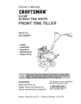
5.0 P
17 raNCHTINE WIDTH
REAR TiNE TILLER WiTH
COUNTER ROTATING TINES
= Assembly
= Operation
- Customer Responsibilities
- Service and Adjustments
- Repair Parts
Sears, Roebuck and Co., Hoffman Estates, IL 60179 U.S.A.
i
illll
llllll
llll
A
Safe Operation
SAFETY RULES Powered
Practices for Walk-Behind
TRAINING
•
Read the Owner's Manua! carefully. Be thoroughly
familiar' with the controls and the proper use of the
equipment° Know how to stop the unit and disengage
the controls quickly.
= Never allow children to operate the equipment° Never
allow adults to operate the equipment without proper
instruction_
•
Keep the area ofoperation clear of al! persons,particularly small children, and pets.
°
°
°
°
•
•
°
•
°
•
°
°
°
•
°
°
Thoroughly inspectthe areawhere the equipment isto
be used and remove all foreign objects.
Disengage all clutches and shift into neutral before
starting the engine (motor).
Do not operate the equipment without wearing adequate outer garments. Wear footwear that will improve footing on slippery surfaces.
Handle fuel with care; it is highly flammable.
Use an approved fuel container.
Never add fuel to a running engine or' hot engine.
Fill fuel tank outdoors with extreme care. Never fill fuel
tank indoors.
Replace gasoline cap securely and clean up spilled
fuel before restarting.
Use extension cords and receptacles as specified by
the manufacturer for all units with electric drive motors
or electric starting motors°
Never attempt to make any adjustments while the
engine (motor) is running (except where specifically
recommended by manufacturer).
MAINTENANCE
•
•
•
•
•
•
•
•
•
AND STORAGE
Keep machine, attachments, and accessories in safe
working condition..
Check shear pins, engine mounting bolts, and other
bolts at frequent intervals for proper tightness to be
sure the equipment is in safe working condition
Never store the machine with fuel in the fuel tank inside
a building where ignition sources are present, such as
hot water and space heaters, clothes dryers, and the
like. Allow the engine to cool before storing in any
enclosure.
Always refer to the operator's guide instructions for
important details if the tiller is to be stored for an
extended period.
°
•
°
- IMPORTANT
-
CAUTIONS, IMPORTANTS,
AND NOTES ARE A MEANS
OF ATTRACTING
ATTENTION
TO IMPORTANT
OR
CRITICAL INFORMATION
IN THIS MANUAL,
IMPORTANT.* USED TO ALERT YOU THAT THERE ISA
POSSIBILITY
OF DAMAGING THIS EQUIPMENT
OPERATION
•
°
Keep children and pets away
Do not overload the machine capacity by attempting to
till too deep at too fast a rate.,
Never operate the machine at high speeds on slippery
surfaces. Look behind and use care when backing.
Never allow bystanders near the unit,
Use only attachments and accessories approved by
the manufacturer of the tiller (such as wheel weights,
counterweights, cabs, and the like).
Never operate the tiller' without good visibility or lighL
Be careful when tilling in hard ground. The tines may
catch in the ground and propel the tiller forward, if this
occurs, let go of the handlebars and do not restrain the
machine.
°
PREPARATION
A
Rotary Tillers
Do not put hands or feet near or under rotating parts.
Exercise extreme caution when operating on or crossinggravel drives, walks, or roads. Stay alert for hidden
hazards or traffic. Do not carry passengers°
After striking a foreign object, stop the engine (motor),
remove the wire from the spark plug, thoroughly inspect the tiller for any damage, and repair the damage
before restarting and operating the tiller.
Exercise caution to avoid slipping or falling.
if the unit should start to vibrate abnormally, stop the
engine (motor') and check immediately for the cause.
Vibration is generally a warning of trouble.
Stop the engine (motor) when leaving the operating
position.
Take all possible precautions when leaving the machine unattended. Disengage the tines, shift into
neutral, and stop the engine.
Before cleaning, repairing, or inspecting, shut off the
engine and make certain all moving parts have stopped.
Disconnect the spark plug wire, and keep the wire
away from the plug to prevent accidental starting.
Disconnect the cord on electric motors.
Do not run the engine indoors; exhaust fumes are
dangerous.
Never operate the tiller without proper' guards, plates,
or other safety protective devices in place.
NOTE: Gives essential information that will aid you to
better understand, incorporate, or execute a particufar set
of instructions.
.................
,,,,,,
,, ,,,,,,,,,,,,,,,
A
,,,,,,,,,, ,,,,,,,
portant safety precautions.
It means
CAUTION!!! BECOME ALERT[!! YOUR
Look for this symbol to point out imSAFETY IS INVOLVED.
............
! _b
ILIJLI
,,,,,
IIIIUIIUIII
plug
wire and
place wire
where itspark
canCAUTION:
Always
disconnect
not contact spark plug in order to prevent accidental starting when setting
up, transporting, adjusting or making
repa=rs.
WARNING
A
The engine exhaust from this product contains chemicals known to the State of California to cause cancer, birth defects, or other
reproductive
harm.
2
CONGRATULATIONS on your purchase of a Sears Tillero
it has been designed, engineered and manufactured to
give you the best possible dependability and performance
PRODUCT
Should you experience any problems you cannot easily
remedy, please contact your nearest authorized Sears
Service Center/Departmento They have competent, welltrained technicians and the proper tools to service or repair
this unit.
Please read and retain this manual., The instructions will
enable you to assemble and maintain your tiller proper¥
Always observe the "SAFETY RULES".
MODEL
NUMBER
SPECIFICATIONS
HORSEPOWER:
5,0 HP
DISPLACEMENT:
9°03 cu ino(148cc)
GASOLINECAPACITY:
3 Quarts
Unleaded Regular
OIL (API_SF/SG):
(CAPACITY:20 oz,)
SAE 30 (Above 32°F)
SAE 5W-30 (Below 32°F)
SPARK PLUG:
Champion
(GAP:
RJtgLM
,030")
(STD361458)
917.295852
SERIAL
NUMBER
MAINTENANCE
AGREEMENT
A Sears Maintenance Agreement is available on this prod _
uct. Contact your nearest Sears store for details,
DATE OF
PURCHASE
CUSTOMER
THE MODEL AND SERIAL NUMBERS WILL BE
FOUND ON THE MODEL PLATE ATTACHED TO
THE TOP OF THE TRANSMISSIONn
YOU SHOULD RECORD BOTH SERIAL NUMBER
AND DATE OF PURCHASE AND KEEP IN A SAFE
PLACE FOR FUTURE REFERENCE.
RESPONSIBILITIES
•
Read and observe the safety rules,
•
Follow a regular schedule in maintaining, caring for and
using your ti_lero
Follow the instructions
under the "Customer
Responsibilities" and "Storage" sections of this Owner's
Manual°
°
IMPORTANT:
THtS UN]T IS EQUIPPED WITH AN INTERNAL COMBUSTION ENGINE AND SHOULD NOT BE USED ON
OR NEAR ANY UNIMPROVED
FOREST-COVERED,
BRUSH-COVERED
OR GRASS COVERED LAND UNLESS THE
ENGINE'S EXHAUST SYSTEM IS EQUIPPED WITH A SPARK ARRESTER MEETING APPLICABLE
LOCAL OR STATE
LAWS (IF ANY).. IF A SPARKARRESTER
IS USED, IT SHOULD BE MAINTAINED IN EFFECTIVE WORKING ORDER BY
THE OPERATOR
IN THE STATE OF CALIFORNIA THE ABOVE IS REQUIRED BY LAW (SECTION 4442 OF THE CALIFORNIA
PUBLIC
RESOURCES
CODE}. OTHER STATES MAY HAVE SIMILAR LAWS. FEDERAL LAWS APPLY ON FEDERAL LANDS,
SEE YOUR SEARS AUTHORIZED SERVICE CENTER/DEPARTMENT
FOR SPARK ARRESTER
REFER TO THE REPAIR
PARTS SECTION OF THIS MANUAL FOR PART NUMBER_
LIMITED TWO YEAR WARRANTY
ON CRAFTSMAN
TILLER
For two years from date of purchase, when this Craftsman Tiller is maintained, lubricated, and tuned up according to
the operating and maintenance instructions in the owner's manual, Sears will repair free of charge any defect in
material or workmanship.
This Warranty does not cover:
•
Expendable items which become worn during normal use, such as tines, spark plugs, air cleaners and belts
°
Repairs necessary because of operator abuse or negtigence, including bent crankshafts and the failure to
maintain the equipment according to the instructions contained in the owner's manual,
o
If this Craftsman Tiller is used for commercial or rental purposes, this Warranty applies for only 30 days from the
date of purchase,
WARRANTY SERVICE IS AVAILABLE BY RETURNING THE CRAFTSMAN TILLER TO THE NEAREST SEARS
SERVICE CENTER/DEPARTMENT IN THE UNITED STATES. THIS WARRANTY APPLIES ONLY WHILE THIS
PRODUCT IS IN USE IN THE UNITED STATES,,
This Warranty gives you specific legal rights, and you may also have other rights which vary from state to state
SEARS, ROEBUCK AND CO. D/817 WA, HOFFMAN ESTATES, ILLINOIS 60179
3
TABLE OF CONTENTS
SA
FEI_"_
RULES
............................................................
MAINTENANCE SCHEDULE ...................................... 13
SERVICE & ADJUSTMENTS ................................. 15-18
STORAG E ...................................................................
19
TROUBLESHOOTING ................................................. 20
REPAIR PARTS-TILLER ........................................ 21-27
REPAIR PARTS-ENGINE ...................................... 28-32
SERVICE/PARTS ORDERING ................ BACK COVER
2
CUSTOMER RESPONSIBILITIES ...................... 3,13-15
PRODUCT SPECIFICATIONS ...................................... 3
WARRANTY ................................................................... 3
ACCESSORIES ............................................................. 5
ASSEMBLY ................................................................ 6-8
OPERATION ............................................................. 9-12
INDEX
A
Engine (cont'd)
R
Lubrication ................................ 14
Repair Parts:
Oil Level ...............................................
11
Tiller ..............................................
21-27
Adjustments:
Oil Type .................................11,14
Engine ................................. 28-32
Carburetor .......................................
18
Spark Plug ..................................15
Depth Stake ...................................
10
Rules for Safe Operation ....................2
Starting ..............................................
12
Handle Height ................................
15
Stopplng .................................... 10
Side Shields .............................. 11
S
Storage .............................................
19
Throttle .......................................18
Winter Operation ...................... 14
Service
&
Adjustments:
Tines ...............................................
17
Carburetor. .....................................
18
V-Belt (Ground Drive) ................t6
F
Handle
Height
.......................................
15
Air Cleaner ........................................ 14
Side Shields .....................................
11
Fuel:
Throttle .....................................................
18
Filling
Tank
..................................
11
B
Tines ...............................................
17
Storage .........................................
19
Belt:
V-Belt (Ground Drive) .................16
Type ..............................................
11
Wheels ....................................... 15
Belt Guard ...........................................
16 Finish:
Repair' Parts .................................
22
Maintenance ............................. 15 Service:
V-Belt (Ground Drive) ...............16
Repair Parts ................................
21-32
Service
Record
...............................
13
H
C
Shear Pins:
Handle:
Operation ......................................12
Cooling System .................................14
Height Adjustment ........................
15
Repair' Parts ...................................
26
Controls:
Repair Parts ..................................
2t
Spark Plug:
Choke ...............................................
9
Gap ............................................. 3
Throttle ........................................ 9
L
Maintenance ............................ 15
Drive (Tines) ........................................
9 Lubrication:
Cultivating ........................................ 12
Lubrication Chart .........................
13 Storage:
Fuel System .............................. 19
Customer Responsibilities:
Engine ...................................... 14
Tiller, ........................................... 19
Air Cleaner'. ..................................14
Cooling System ..........................14
M
T
Finish ...............................................
15
Muffler:
Maintenance Schedule ..............13
Tilling ..............................................10,12
Maintenance ......................................
15
Muffler. ........................................ 15
Tines:
Spark
Arrester
..............................
3
Oil Change .....................................
14
Arrangement/Replacement .... 17
Spark Plug .......................................
15
Operation .........................................
10
O
Tines ........................................... !7
Repair Parts ................................26
Transmission .................................
15 Oil:
Shear Pins ..................................12
V-Bett (Ground Drive) .............. 16
Level ........................................ 11 Transmission:
Type ................................................
11,!4
Maintenance .....................................
15
D
Operation:
Repair Parts ....................................
24
Cultivating ...................................12 Troubleshooting ..........................................
Depth Stake:
20
Fill Fuel Tank ............................ 11
Adjustment ..........
.............................10
Starting Engine ......................... 12 Transporting ..................................... 11
Repair Parts .............................. 25
Stopping Tines & Engine ......... 10
W
Tilling ..........................................10
E
Tilling Hints ......................................
12 Warranty ....................................................
3
Engine:
Tine Operation .......................... 10
Wheels:
Air Cleaner'. ..................................14
Transporting Tiller .........................
11
Removal ..........................................
15
Cooling System ........................ 14
Winter Operation .......................14
Fuel Type .........................................
11
Repair Parts ...............................23
Accessories .........................................5
4
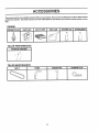
ACCESSOR
These accessories were available when the tiller was purchased. They are also available at most Sears Retail outlets
and Service Centers. Most Sears Stores can order repair parts for you when you provide the model number of your
tiller.
ENGINE
sPARK
PLUG
MUFFLER
AIRF,LTER
GAS CAN
ENGINE
OIL
STASiUZER
_
F'
TILLER
PERFORMANCE
FURROW
OPENER
f'
TILLER MAINTENANCE
, ,,,L
,
, ....
BELT
TINES
SHEAR
5
PIN
HAIRPIN
CLIP
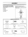
Your new tiller has been assembled at the factory with exception of those parts left unassembled for shipping purposes, To
ensure safe and proper operation of your tiller all parts and hardware you assemble must be tightened securely, Use the
correct toots as necessary to insure proper tightness.
TOOLS
REQUIRED
FOR ASSEMBLY
OPERATOR'S
A socket wrench set will make assembly easier. Standard
wrench sizes are listed,
POSITION
(See Fig. 1)
When right or left hand is mentioned in this manual, it
means when you are in the operating position (standing
behind tiller handles).
(t) Utility knife
(1) Wire cutter
FRONT
(1) Screwdriver
(1) Tire pressure gauge
(1) Pair of pliers
(t) 9/16" wrench
RIGHT
LEFT
OPERATOR'S
POSITION
FIG. 1
CONTENTS OF HARDWARE
PACK
,,,H,
G
(1) Carriage Bolt 3/8-16 UNC x I Gr 5
(2) Handle Locks
.........................
(1) Center Locknut 3/8-16 UNC
Ulll
@
(1) Flat Washer 13/32 x 1 x 11 Ga.
................................
(2) Hairpin Clips
(1) Cable Clip
(!) Handle Lock Lever'
, ,,,L
(1) Pivot Bolt
3/8-16 UNC Grade 5
6
Extra Shear Pins
, i i,i i,,i,,i,i
ASS MBLY
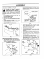
UNPACKING
CARTON
.........................
Grasp handle assembly. Hold in "up" position. Be sure
handle lock remains in gearcase notch_ Slide handle
assembly into position_
(See Fig. 2)
i ll,,,i
i ,i
i
i,
:
staples when handling or disposing of
I
CAUTION:
Be careful of exposed
!
cartoning material.
,,,
J
i,i
i
I _
...........
fo--_;;_:'.'_.,.,
IMPORTANT: WHEN UNPACKING AND ASSEMBLING
TILLER, BE CAREFUL NOT TO STRETCH OR KINK
CABLES
°
While holding handle assembly, cut cable ties securing
handle assembly to top frame and depth stake.. Let
handle assembly rest on tiller_
,
o
Remove top frame of carton..
Slowly ease handle assembly up and place on top of
carton,
•
Cut down right hand front and right hand rear corners
of carton, lay side carton wall down°
•
Remove packing material from handle assembly.
•
Separate shift rod from handle assembly°
HANDLE
__ _
ASSEMBLY
"UP" POSIT, ON
_'_-
": °",.. TIGHTEN HXNDLE i
"". LOCK LEVER TO I
_,
_-_" _._'_
HOLD
I"_0OSEN
HANDLE
_
__:_:
t LOCKLEVERTO _
_-_ _
!,,ow ,
.....
I
_
FIG. 4
•
SHIFT ROD
°
Rotate handle assembly down_ Insert rear carriage
bolt first, with head of bolt on L.H. side of tiller and
loosely assemble IocknuL (See Fig..5)
Insert pivot bolt in front part of plate
•
Cut down rear panel of carton.
•
Lower the handle assembly. Tighten bolts so handle
moves with some resistance. This will a[!ow for easier
adjustment,
Place flat washer on threaded end of handle lock lever
\
•
•
HANDLE
ASSEMBLY
i
/
/-_:.:::_i
°
i
insert handle lock lever through handle base and
gearcase. Screw in handle lock lever just enough to
hold lever in ptace.
insertsecond handle lock (with teeth inward) in the slot
of the handle base (just inside of washer)..
I .......
FIG. 2
INSTALL
°
HANDLE
o
(See Figs. 3, 4, and 5)
Insert one handle lock (with teeth facing outward) in
gearcase notch,. (Apply grease on smooth side of
handle tock to aid in keeping lock in place until handle
assembly is Iowered into positionr)
VIEW FROM R°H. SIDE OF TILLER
With handle assembly in lowest position, securely
tighten handle lock lever by rotating clockwise Leaving handle assembly in lowest position will make it
easier to remove tiller from carton.
GEARCASE
REAR
CARRIAGE
HANDLE
LOCK
FLAT
WASHER
SLOT
BOLT
HANDLE
\
LOCK
HANDLE ASSEMBLY
LEVER
;0
GEARCASE
NOTCH
ot .- L"Do" LE
HANDLE
BASE
LOCKNUT
FIG. 5
FIG. 3
7
PIVOT
BOLT
CONNECTSHIFT ROD (See Fig. 6)
REMOVE TILLER
*
Insert end of shift rod farthest from bend into hole of
shift lever indicator
•
Make sure shift lever indicator is in "N" (neutral) posi
tion (See Fig 6)
•
insert hairpin c|ip through hole of shift rod to secure
Insert other end of shift rod into hole in shift lever
•
Tilt tiller forward by lifting handIe Separate cardboard
cover from leveling shietd
•
Insert second hairpin clip through hole of shift rod
,,
Rotate tiller handle to the right and putt tiller out of
carton
ATTACH THIS END
TO SHIFT LEVER
INDICATOR
ATTACH THIS
END TO SHIFT
INSERT
•
\
CABLE
FROM CRATE
CLIP
(See
Fig. 7)
Insert plastic cable clip into hole on the back of handle
coiumno Push cables into cfip
HANDLE
COLUMN
SHIFT ROD
SHIFT
LEVER
INDICATOR
CABLES
LE CLIP
FIG, 7
CHECK TIRE PRESSURE
The tires on your unit were overinflated at the factory for
shipping purposes
Correct and equal tire pressure is
important for' best tiffingperformance,.
•
Reduce tire pressure to 20 PSi°
SHIFT LEVER
HANDLE
•
CLIP
SHIFT ROD
FIG, 6
8
HEIGHT
Handle height may be adjusted to better suit operator
(See "TO ADJUST HANDLE HEIGHT" tn the Service
and Adjustments section of this manual)°
OPERATION
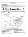
KNOW YOUR TILLER
READ THIS OWNER'S MANUAL AND SAFETY RlJLES BEFORE OPERATING YOUR TILLER.
Compare the illustrationswith yourtiller to familiarize yourself with the location of various controls and adjustments, Save
this manua! for future reference,
These symbols may appear on your Tiller or in literature supplied with the product, Learn and understand their
meaning.
RUN
CAUTION
OR WARNING
ENGINE
ON
...................................
i
iiiiii
i
DRIVE
CONTROL
BAR
ENGINE
OFF
FAST
SLOW
FUEL
CHOKE
OiL
STOP O
, i_11_1,111,111_11,1,1,1,1
THROTTLE
CONTROL
SHIFT LEVER
SHIFT LEVER
INDICATOR
CHOKE CONTROL
RECOIL
STARTER
HANDLE
DEPTH STAKE
LEVELING
SHIELD
i
OUTER
SIDE
SHIELD
FIG. 8
MEETS ANSI SAFETY REQUIREMENTS
Our tillers conform to the safety standards of the American National Standards Institute,
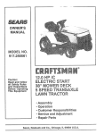
SHIFT LEVER - Used to shift transmission gears
SHIFT LEVER INDICATOR - Shows which gear the
transmission is in,,
RECOIL STARTER HANDLE - Used to start the engine
CHOKE CONTROL - Used when starting a cold engine
DRIVE CONTROL BAR - Used to engage tines,
DEPTH STAKE - Controls depth at which tiiler will dig.,
LEVELING SHIELD - Levels titled soil,,
OUTER SIDE SHIELD - Adjustable to protect small plants
from being buried°
THROTTLE CONTROL _ Used to control engine speed,
9
OPERATION
The operation of any tiller can result in foreign objects thrown into the eyes, which can
result in severe eye damage. Always wear safety glasses or eye shields before starting
your tiller and while tilling° We recommend a wide vision safety mask over the spectacles
or standard safety glasses.
...............................................
,,,,,
,,,,
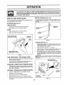
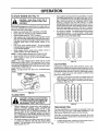
HOW TO USE YOUR TILLER
DEPTH STAKE (See Fig. 10)
Know how to operate all controls before adding fuel and
oil or attempting to start engine.
The depth stake can be raised or lowered toallow you more
versatile tilling and cultivating, or to more easily transport
your tiller.
STOPPING
(See Fig. 9)
TINES AND DRIVE
•
•
Release drive control bar to stop movemer_t,,
Move shift lever to "N" (neutral) position°
qSPORT
POSITION
SHALLOWES'i
TILLING
ENGINE
•
Move throttle control to "STOP" position_
°
Never use choke to stop engine_
TILLING
DRIVE CONTROL BAR
"ENGAGED" POSITION
STAKE
DEPTH
SHIFT
LEVER
FIG, 10
TILLING
°
°
Hold the drive control bar against the handle to start
tilling movement° Tines and wheels will both turn,
° Move throttle control to "FAST" pc)sition fordeep tilling.
To cultivate, throttle control can be set at any desired
speed, depending on how fast or slow you wish to
cultivate.
IMPORTANT: ALWAYS RELEASE DRIVE CONTROL BAR
BEFORE MOVING SHIFT LEVER 1NTO ANOTHER
POSITION
DRIVE CONTROL BAR
"DISENGAGED" POSITION
FIG. 9
•
•
Release depth stake pin. Pull the depth stake up lor
increased tilling depth. Place depth stake pin in hole of
depth stake to lock in position.,
Place shift lever indicator in 'q_' position.
°
/
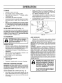
TINE OPERATION
(See Fig. 11)
- WITH WHEEL DRIVE
Always release drive control bar before moving shift
lever into another position.
Tine movement is achieved by moving shift lever to "T"
(till) position and engaging drive control bar.
DEPTH STAKE PIN
'RELEASED
POSITION
FORWARD - WHEELS ON LY/TIN ES STOPPED
•
Release drive controf bar and move shift lever indicator
to "F" (forward) position,, Engage drive control bar and
tiller will move forward.
REVERSE - WHEELS ONLY/TINES
STOPPED
•
DO NOT STAND DIRECTLY BEHIND TILLER.
•
Release the drive control bar.
°
•
Move throttle control to "SLOW" position.
Move shift lever indicator to "R" (reverse) position.
°
Hold drive control bar against the handle to start titler
movement.
"LOCKED"
POSITION
NUT "A"
OUTER
SIDE SHIELD
NUT "B"
FIG. 11
10
OPERATnON
Engine oil should be to point of overflowing
For
approximate capacity see "PRODUCT SPECIFiCATIONS" on page 3 of this manual. All oil must meet
A PJ Service Classification SF or SG
TURNING
•
Release the drive control bar,
°
Move throttle control to "SLOW" position.
.
Place shift lever indicator in "F" (forward) position,
Tines will not turn
o
Lift handle to raise tines out of ground,
°
Swing the handle in the opposite direction you wish to
turn, being careful to keep feet and legs away from
tines.
°
For cold weather operation you should change oil for
easier starting (See oil viscosity chart in the Customer
Responsibilities section of this manual)
°
To change engine oil, see the Customer Responsibilities section in this manual
When you have completed your turn-around, release
the drive control bar and lower handle. Place shift lever
in 'T' (till) position and move throttle control to desired
speed. To begin tilling, hold drive control bar against
the handle,
OUTER SIDE SHIELDS
OIL
(See Fig. 11)
OIL
FILLER
PLUG
The front edges of the outer side shields are slotted so that
the shields can be raised for deep tilling and lowered for
shallow tilling to protect small plants from being buried,
Loosen nut "A" in slot and nut "B", Move shield to desired
position (both sides). Retighten nuts°
DRAIN
PLUG
FIG. 12
TO TRANSPORT
ADD GASOLINE
•
Fill fuel tank.
Use fresh, clean, regular unleaded
gasoline. (Use of leaded gasoline will increase carbon
and lead oxide deposits and reduce valve tile
IMPORTANT:
WHEN OPERATING IN TEMPERATURES
BELOW 32°F (0°C), USE FRESH, CLEAN, WINTER GRADE
GASOLINE TO HELP iNSURE GOOD COLD WEATHER
STARTING
CAUTION: Before lifting or transporting, allow tiller engine and muffler to
cool. Disconnect sparkplugwire. Drain
gasoline from fuel tank.
i
i
ll,l,l,i,
AROUND THE YARD
°
-
Release the depth stake pin. Move the depth stake
down to the top hole for transporting the tiller. Place
depth stake pin in hole of depth stake to lock in position.
This prevents tines from scuffing the ground.
Place shift lever indicator in "F" (forward) position for
transporting.
=
Hold the drive control bar against the handle to start
tiller movement_ Tines wil! not turn_
-
Move throttle control to desired speed.
WARNING: Experience indicates that alcohol blended
fuels (called gasohol or using ethanol or methanol) can
attract moisture which leads to separation and formation of
acids during storage_ Acidic gas can damage the fuel
system of an engine while in storage. To avoid engine
problems, the fuel system should be emptied before
storage of 30 days or longer. Drain the gas tank, start the
engine and let it run until the fuel lines and carburetor are
empty. Use fresh fuel next season. See Storage section
of this manual for additional information. Never use engine
or carburetor cleaner products in the fue{ tank or permanent
damage may occur_
AROUND TOWN
•
•
Disconnect spark plug wire°
Drain fuel tank.
•
Transport in upright position to prevent oil leakage.
CAUTION: Fill to within 1/2 inch of top
of fuel tank to prevent spills and to
allow for fuel expansion. If gasoline is
accidentally spilled, move machine
away from area of spill. Avoid creating
any source of ignition until gasoline
vapors have disappeared.
BEFORE STARTING ENGINE
IMPORTANT:
BE VERY CAREFUL NOT TO ALLOW DIRT
TO ENTER THE ENGINE WHEN CHECKING OR ADDING
OIL OR FUEL. USE CLEAN OIL AND FUEL AND STORE
iN APPROVED, CLEAN, COVERED CONTAINERS
USE
CLEAN FILL FUNNELS.
CHECK
Do not overfill. Wipe off any spilled oil
or fuel. Do not store, spill or use gasoline near an open flame.
ENGINE OIL LEVEL (See Fig. 12)
•
The engine in your unit has been shipped, from the
factory, already filled with SAE 30 summer weight oil
°
With engine level, clean area around oil filler plug and
remove ptug_
:
11
Hi,l/ill,
OPERATION
TO START ENGINE (See Fig. 17)
i
°
Soil conditions are importantfor proper tiIling. Tines will
not readily penetrate dry, hard soil which may contribute to excessive bounce and difficult handling of your
tiller. Hard soil should be moistened before tilling;
however, extremely wet soil will "ba!l-up" or clump
during tilIing. Wait until the soil is less wet in order to
achieve the best results_ When tilling inthe fall, remove
vines and long grass to prevent them from wrapping
around the fine shaft and slowing your tilling operation.
Do not leanon handle_ This takes weight off the wheels
and reduces traction. To get through a rea_ly tough
section of sod or hard ground, apply upward pressure
on handle or tower the depth stake_
......................
When starting engine for the first time or if engine has run
out offuel, itwilltake extra pulisof the recoil starter to move
fuel from the tank to the engine.
Make sure spark plug wire is properly connected°
.
Move shift lever indicator to "N" (neutral) position.
•
Place throttle control in "FAST" position_
•
With engine fully choked, grasp recoil starter handle
with one hand and grasp tiller handle with other hand._
Pull rope out slowly until engine reaches start of compresston cycle (rope will pull slightly harder at this
point),.
•
Pull recoil starter handle quickly. Do not let starter
handle snap back against starter_ Repeat if necessary
in half choked position.
° When engine starts, slowly move choke control to
"RUN" position as engine warms up.
NOTE: A warm engine requires less choking to start_
•
Move throttle control to desired running position_
•
Allow engine to warm up for a few minutes before
engaging tines_
NOTE: If at a high altitude (above 3000 feet) or in cold
temperatures (below 32°F), the carburetor fuel mixture
may need to be adjusted for best engine performance. See
"TO ADJUST CARBURETOR" in the Service and Adjustments section of this manual.
NOTE; tf engine does not start, see "Troubleshooting
Points".
CHOKE
"_ CONTROL
.
FIG. 14
CULTIVATING
Cultivating is destroying the weeds between rows to prevent them from robbing nourishment and moistu re from the
plants, Atthe same time, breaking up the upper layer of soil
crust will hetp retain moisture in the soil. Best digging depth
is 1" to 3"_ Lower the outer side shields to protect small
plants from being buried,
° Cultivate up and down the rows at a speed which will
allow tines to uproot weeds and leave the ground in
rough condition, promoting no further growth of weeds
and grass (See Fig, 15)_
©©Q
©
© ©!©
i©
HANDLE
FIG. 13
TILLING
HINTS
handl,ng your tiller, start actual field
use
with throttle
in slow
position (midCAUTION:
Unttlyou
are accustomedto
way between "FAST" and "IDLE")
© ©!© ©i©
I
|I
Tilling is digging into, turning over, and breaking up
packed soil before planting_ Loose, unpacked soil
helps root growth_ Best tilling depth is 4" to 6". A tiller
will also clear the soil of unwanted vegetation. The
decomposition of this vegetable matter enriches the
soil Depending on the climate (rainfall and wind), it
may be advisable to till the soil atthe end of the growing
season to further condition the soil.
For easier handling of your'tiller, leave about 8 inches
of untilled soil between the first and second tilling
passes. The third pass wil! be between the first and
12
second (See Fig. !4).
_,,_
FIG,, 15
TINE SHEAR PINS
The tine assemblies on your' tiller are secured to the tine
shaft with shear pins (See "TINE REPLACEMENT" in the
Service and Adjustments section of this manual).
If the tiller is unusually overloaded or jammed, the shear
pins are designed to break before internal damage occurs
to the transmission_
°
if shear pin(s) break, replace only with those shown in
the Repair Parts section of this manual.
CUSTOMER
i
i
.......
i,,ll,l,l,llll
, iii
,111
I'"
,,i,iii I,LII_
IINI'"I'III'I'I
D/Zz
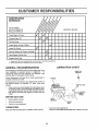
FILL IN DATES
AS YOU COMPLETE
REGULAR SERVICE
i'nii iiiqqq,ll
iiii
SERVICE
/
iiiiiii
Check Engine Oil Level
ii
, i
i l llIHrNNNNI
.........................
i/"
Oil Pivot Points
i ii i
DATES
i!
Change Engine Oil
i
IES
I
MAINTENANCE
SCHEDULE
........................
BIL
RESPO
i i
,, Nil
!/
Inspect Spark Arrester/ Muffler
inspect Air Screen
If
...........i,ii
..............................
Clean or Replace Air Cleaner Cartridge
...............................
'
Clean Engine Cylinder Fins
..................
m,HHNU
U,
If
Replace Spark Plug
If
I - Change more olten when operating under a heavy load or in high ambient temperatures,
2 - Service more often wheri operating tn didy or dusty conditions,
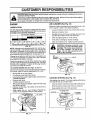
LUBRICATION
GENERAL RECOMMENDATIONS
CHART
The warranty on this tiller does not cover items that have
been subjected to operator abuse or negligence,. To
receive full value from the warranty, the operator must
maintain tiller as instructed in this manual,
* THROTTLE
CONTROL
Some adjustments will need to be made periodically to
properly maintain your tiller.
"* ENGINE
,
'.
All adjustments in the Service and Adjustments section of
this manual should be checked at least once each
season.
Once a year you should replace the spark plug, clean
or replace air filter, and check tines and belts for wear.
A new spark plug and clean air filter assure proper airfuel mixture and help your engine run better and last
longer.
/
i_ ,_,,
1\if, t ....
_
\
HINGES
BEFORE EACH USE
•
Check engine oil level
•
°
Check tine operation°
Check for loose fasteners°
BRACKET
\
\
LUBRICATION
* WHEEL
HUB
* SAE 30 OR I0W-30 MOTOR OIL
** REFER TO CUSTOMER RESPONSIBILITIES
Keep unit well lubricated (See "LUBRICATION CHART").
13
"ENGINE"
SECTION
CUSTOMER
_"'""
" "" ''
q'....
::
R
ILITIES
.......................
..............
...............................................................
iiii,,,,,,,,'
.........................
'....... ,, ,u ,,,,,
_,_
Disconnect spark plug wire before performingany maintenance(except carburetor adjustment) to prevent
i
!
Prevent fires! Keep the engine free of grass,leaves, spilledoil, or fuel Removefuel from tank before tipping
accidental
starting of engine.
unit
for maintenance.
Cleanmuffler area of all grass, dirt, and debris.
Do not touch hot muffleror cylinderfins as contactmay cause burns.
ENGINE
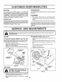
AIR CLEANER (See Fig, 18)
LUBRICATION
Service air cleaner cartridge every twenty-five hours, more
often if engine is used in very dust"y conditions..
*
Loosen air cleaner screws, one on each side of cover_
Use only high quality detergent oil rated with APt service
classification SF orSG. Selectthe oil s SAE viscosity grade
according to your' expected temperature.
SAEVISCOSITY
GRADES
co
-30 °
-20 _
-
30.
-_0_
0_,
10=
20 _'
30"
•
Remove air cleaner cover,
Carefully remove air cleaner cartridge. Be careful Do
not allow dirt or debris to fall into carburetor'.
•
Clean by tapping gently on a fiat surface_
•
•
If very dirty o_"damaged, replace cartridge,
Clean and replace cover,, Tighten screws securely,.
40 _
................
•
FIG. 16
NOTE: Although multi-viscosity oils(5W-30, 10W-30, etc.)
improve starting in cold weather, these mufti-viscosity oils
will result in increased oil consumption when used above
32°F (0°C). Check your engine oil level more frequently to
avoid possible engine damage from running low on oil
t
tutllll
lllllll,liH
........
as kerosene, are not to be used to clean
I
cartridge. They may cause deteriora|
tion of the cartridge. Do not oil car|
tridge. Do not use pressurized air to
I
clean or dry cartridge.
,..............................................................
Change the oil after the first two hours of operation and
every 25 hours thereafter' or at least once a year if the tiller
is not used for 25 hours in one year'_
Check the crankcase oil level before starting the engine
and after each five (5) hours of continuous use. Add SAE
30 motor oil or equivalent. Tighten oil filler' plug securely
each time you check the oil level,.
AIR
CLEANER
TO CHANGE ENGINE OIL (See Figs. 16 and 17)
Determine temperature range expected before oil change,.
All oil must meet API service classification SF or SG
•
•
•
Be sure tiller is on level surface,,
Oil will drain more freety when warrn_
Use a funnel to prevent oil spill on tiller, and catch oil in
a suitable container'.
COOLING
•
•
Remove drain plug.
Tip tiller forward to drain oil
Your engine is air cooled. For proper engine performance
and long life keep your engine clean.
•
After oil has drained completely, replace oil drain plug
and tighten securely,,
Remove oil filler' plug. Be careful not to allow dirt to
enter the engine.
Refill engine with oil. See "CHECK ENGINE OIL
LEVEL" in the Operation section of this manual.
•
Clean air screen frequently using a stiff-bristled brush,
•
•
Remove blower' housing and clean as necessary,
Keep cylinder fins free of dirt and chaff.
•
•
FIG. 18
SYSTEM
(See
Fig. 19)
CYLINDERFINS
BLOWER
HOUSING
OIL
AIR
DRAIN
_
)
PLUG\
,OIL RLLER
PLUG
FIGo17
FIG. 19
14
SCREEN
CUSTOMER
RESPONSIBBLmTIES
MUFFLER
TRANSMISSION
Do not operate tiller without muffler. Do not tamper with
exhaust system° Damaged mufflers or spark arresters
could create a fire hazar& Inspect periodically and replace
if necessary° if your engine is equipped with a spark
arrester screen assembly, remove every 50 hours for
cleaning and inspection.. Replace if damaged°
Your transmissionis sealed and will only require lubrication
if serviced.
CLEANING
SPARK PLUG
Replace spark plugs at the beginning of each tilling season
or after every 50 hoursof use, whbhevercomes first. Spark
plug type and gap setting is shown in "PRODUCT SPECIFICATIONS" on page 3 of this manual..
•
Clean engine, wheels, finish, etc. of all foreign matter,
o
Keep finished surfaces and wheels free of a[! gasoline,
oil, etc.
°
Protect painted surfaces with automotive type wax.
We do not recommend using a garden hose to clean your
unit unless the muffler, air filter and carburetor are covered
to keep water ouL Water in engine can result in a shortened
engine life.
CE AND ADJUSTMENTS
.............
I &
i,nl,nl,,,ll,i
i
i
I n /i
lllllUU,ll,l,i
CAUTION:
spark plug wire from spark plug and place wire where it cannot come into
contact
withDisconnect
plug.
...............
1,1,1111
IIII
]llJllllillllili
TILLER
I
I
I
I
I
I
I
I
I
i
II
i
liiliil
ninniinnni
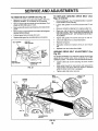
TO REMOVE WHEEL (See Fig. 21 )
Select handle height best suited for your tiliing conditions,.
Handle height will be different when tiller digs into soil..
= First loosen handle lock lever.
•
Place blocks under transmission to keep tiller from
tipping.
Remove outer side shield by removing nuts"A" and "B".
°
Remove inner side shield by removing nuts "C" and
•
Handle can be positioned at different settings between
"HIGH" and "LOW" positions.
°
°
Remove hairpin clip and clevis pin from wheet.
Remove wheel and tire.
•
Retighten handle lock lever securely after adjusting.
°
Repair tire and reassemble_
TO ADJUST
HANDLE
_':
_"
--_
:?Z" z:"-.i.:'
,
"'"_;"_:;S,,
'"
"_\'x
HANDL_OW
-
HEIGHT (See Fig. 20)
"D".
HANDLE (HIGH
/
CLEVIS
POSITION)
'"_:'"
//LEVER
""\___
'
HAIRPIN
CLIP
POSnlON)
NUT "A"
FIG. 20
TIRE
I&
/
CARE
F
NUT "B"
less beads are seated, overinflation
CAUTION:
mounting tires, uncan
cause anWhen
explosion,
•
Maintain 20 pounds of tire pressure. If tire pressures
are not equal, tiller will pull to one side.
-
Keep tires free of gasoline or oil which can damage
rubber°
INNER SIDE
OUTER SHIELD
SIDE
SHIELD
FIG. 21
15
AND ADJUSTM
SE
illlllllll
illll
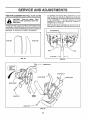
TO REPLACE GROUND
Figs, 22 and 23)
TO REMOVE BELT GUARD (See Fig. 22)
•
•
•
Remove L.H. inner and outer side shields (See "TO
REMOVE WHEEL" in this section of this manual).
Remove hairpin clip and clevis pin from left wheel. Pull
wheel out from tiller about 1 inch.
°
Remove
guard°
Remove
(located
Pull belt
°
Replace belt guard by reversing above procedure_
-
o
BELT (See
Remove beltguard, (See 'TO REMOVE BELT GUAR D"
in this section of this manual).
Loosen belt guides "A" and "B" and also nuts "C" and
°
.gt,
two (2) cap nuts and washers from side of belt
e
e
hex nut and washer from bottom of belt guard
behind wheel).
guard out and away from unit,
o
o
BELT GUARD
DRIVE
CAPNUT
AND WASHER
Remove old belt by slipping from engine puttey firsL
Place new belt in groove of transmission pulley and
into engine pulley. BELT MUST BE iN GROOVE ON
TOP OF iDLER PULLEY, NOTE POSITION OF BELT
TO GUIDES,
Tighten belt guides "A" and "B" and nuts "C" and "D",
Check belt adjustment as described below,
0
Replace belt guard,
o
Reposition wheel and replace clevis pin and hairpin
clip,
Replace inner and outer side shields
HEX NUT
AND
WASHER
(LOCATED
BEHIND
CAP NUT
AND WASHER
":'_'_N
HAIRPIN
CLIP
GROUND
DRIVE
BELT ADJUSTMENT
For proper belt tension, the extension spring should have
about 5/8 inch stretch when drive control bar is in "ENGAGED" position. This tension can be attained as follows:
° Loosen cable clip screw securing the drive control
cable.
•
Slide cable forward for less tension and rearward for
more tension until about 5/8 inch stretch is obtained
while the drive controt bar is engaged,
AND
CLEVIS PIN
FIG. 22
°
Tighten cable clip screw securely,
BELT
GUIDE "A"
CABLE CLIP
SCREW
ENGINE
PULLEY
CONTROL
CABLE
LESS
TENSION
NUT"D"
IDLER
PULLEY
(See
Fig. 23)
EXTEN,
SPRING
TRANSMISSION
PULLEY
FIG. 23
16
SERVICE AND ADJUSTMENTS
ll, i
i,
i
TINE REPLACEMENT
(See Figs. 24, 25 and 26)
ill i,
,
.
To maintain the superb tilling performance of this
machine the tines should be checked for sharpness,
wear, and bending, particularly the tines which are next
to the transmission,
if the gap between the tines
exceeds 3-1/2 inches they should be replaced or
straightened as necessary.
o
New tines should be assembled as shown in Fig 26
Sharpened tine edges wilt rotate rearward from above
i,ll
..............................
i,
CAUTION:
Tines are sharp. Wear
gloves or other protection when handling tines.
,,,_1111
A badly worn tine causes your tiller to work harder and dig
more shallow,. Most important, worn tines cannot chop and
shred organic matter as effectively nor bury it as deeply as
good tines. A tine this worn needs to be replaced°
TRANSMISSION,
\
NEW TINE
WORN T1NE
rlNE
3-112" MAX
FIG. 24
FIG. 25
HAIRPIN CLIP
COUNTER
TINE
ROTATION
HAIRPIN CL1P
SHARP EDGE
SHARP EDGE
SHARP
EDGES
SHEARPIN
SHEAR PIN
FIG. 26
17
SHARP EDGE
SERVICE AND ADJUSTM
..........
,,,,,,,,,,,,,,,
l llUl=l
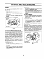
FINAL SETTING
ENGINE
•
TO ADJUST THROTTLE
(See Fig. 27)
•
•
•
°
CONTROL
Start engine and allow to warm for five minutes. Make
final adjustments with engine running at idle and drive
control bar in "DISENGAGED" position
•
With throttle control lever in "SLOW" position, turn idle
needle valve in (clockwise) until engine begins to die
then turn out (counterclockwise) untit engine runs
rough. Turn valve to a point midway between those two
positions.
IDLE RPM ADJUSTMENT
CABLE
Loosen cable clamp screw to allow cable to move_
Move throttle control lever on upper handle to "FAST"
position_
Pull throttle cable out until engine bellcrank is back as
far as it will go..
Hold cable in this position and tighten clamp screw
securely.
°
To adjust idle RPM, rotate throttle linkage counterclockwise and hold against stop while adjusting idle
speed adjusting screw to obtain 1750 RPM Release
throttle linkage.
ACCELERATION TEST
CLAMPSCREW
THROTTLE
CABLE,
•
High speed stop is factory adjusted. Do not adjust or
damage may result,
IMPORTANT: NEVER TAMPER WITH THE ENGINE
GOVERNOR, WHICH IS FACTORY SET FOR PROPER
ENGINE SPEED. OVERSPEEDINGTHE ENGINE ABOVE
THE FACTORY HIGH SPEED SETTING CAN BE
DANGEROUS. 1FYOU THINK THE ENGINE-GOVERNED
HiGH SPEED NEEDS ADJUSTING, CONTACT YOUR
NEAREST SEARS SERVICE CENTER/DEPARTMENT,
WHICH HAS PROPER EQUIPMENT AND EXPERIENCE
BELLCRANK
FIG. 27
TO ADJUST
CARBURETOR
Move throttle control lever from "SLOW" to "FAST"
position.. If engine hesitates or dies, turn needle valve
out (counterclockwise) 1/8 turn, Repeat test and
continue to adjust, if necessary, until engine accelerates smoothly.
(See Fig. 28)
TO MAKE
The carburetor has a high speed jet and has been preset at
the factory and adjustment should not be necessary° However, minor adjustments may be required to compensate
for differences in fuel, temperature, altitude or Ioado If the
carburetor does need adjustment, proceed as follows_
ANY
NECESSARY
THROTTLE LINKAGE
ADJUSTMENTS,
THROTTLE
STOP
in general, turning the idle needle valve in (clockwise)
decreases the supply of fuel to the engine giving a leaner
fuel/air mixture_ Turning the needle valve out (counterclockwise) increases the supply of fuel to the engine giving
a richer fuel/air mixture_
IMPORTANT: DAMAGE TO THE NEEDLES AND THE
SEATS IN CARBURETOR MAY RESULT IF SCREWS ARE
TURNED IN TOO TIGHT.
IDLE SPEED
ADJUSTING SCREW
PRELIMINARY SETTING
•
•
Air cleaner assernbfy must be assernbied to the carburetor when making carburetor adjustments.
Be sure the throttle control cable is adjusted properly
(see above).,
With engine off, turn idle needle valve in (clockwise)
closing it finger tight and then turn valve out (counterclockwise) 1-1/2 turns.
IDLE NEEDLE VALVE
FIG. 28
18
STORAGE
ENGINE OIL
Immediatety prepare you r tiller for storage at the end of the
season or if the unit will not be used for 30 days or more.
CAUTION:
Never store the tiller with
!
where fumes may reach an open flame
gasoline
the tank
a building
or spark, in Allow
theinside
engine
to cool
before storing in any enclosure
I
!!
Drain oi/(with engine warm) and replace with ctean o+!.
(Sea"ENGINE" in the Customer Responsibilities section ol
this manual).
CYLINDERS
TILLER
=
Remove spark plug
Pour ! ounce (29 ml) of oil through spark plug hole into
cylinder,.
Pull starter handle slowly several times to distribute oil
•
Clean entire tiller (See "CLEANING" in the Customer
Responsibilities section of this manual).
°
Replace with new spark plug,
=
Inspect and replace belts, if necessary (See belt re+
placement instructionsin the Service and Adjustments
section of this manual)+
Lubricate as shown in the Customer Responsibilities
section of this manual
OTHER
J_t
+
_m_H
m,
+
.........
°
+
!
-
Be sure that all nuts, bolts and screws are securely
fastened.. Inspect moving parts fordamage, breakage
and wear. Replace if necessary+.
=
Touch up all rusted or chipped paint surfaces; sand
_ightly before painting°
IMPORTANT:
IT IS IMPORTANT TO PREVENT GUM
DEPOSITS
FROM FORMING
LN ESSENTIAL
FUEL
SYSTEM PARTS SUCH AS THE CARBURETOR,
FUEL
FILTER, FUEL HOSE, OR TANK DURING STORAGE..
ALSO,
EXPERIENCE
INDICATES
THAT ALCOHOL
BLENDED
FUELS
(CALLED
GASOHOL
OR USING
ETHANOL OR METHANOL) CAN ATTRACT MOISTURE
WHICH LEADS TO SEPARATION
AND FORMATION OF
ACIDS DURING STORAGE. ACIDtC GAS CAN DAMAGE
THE FUEL SYSTEM OF AN ENGINE WHILE IN STORAGE°
.
Start the engine and let it run until the fuel lines and
carburetor are empty.
-
Never use engine or carburetor cleaner products in the
fuel tank or permanent damage may occur,
Use fresh fuel next season,
,,
.
Replace your gasoline can if your can starts to rust+
Rust and/or dirt in your gasoline will cause problems.,
•
If possible, store your unit indoors and cover it to give
protection from dust and dirt.
Cover your unit with a suitable protective cover that
does not retain moisture, Do not use plastic. Plastic
cannot breathe which allows condensation to form and
will cause your unit to rusL
IMPORTANT: NEVER COVER TILLER WHILE ENGtNE
AND EXHAUST AREAS ARE STILL WARM.
FUEL SYSTEM
Drain the fuel tank..
Do not store gasoline from one season to another.
°
ENGINE
•
,,
NOTE: Fuel stabilizer is an acceptable alternative in
minimizing the formation of fuel gum deposits during storage. Add stabilizer to gasoline in fuel tank or storage
container° Always follow the mix ratio found on stabilizer
container. Run engine at least 10 minutes after adding
stabitizerto allowthe stabilizer to reach the carburetor+ Do
not drain the gas tank and carburetor if using fuel stabilizer.
19
TROUBLESHOOTING
POINTS
PROBLEM
CAUSE
CORRECTION
Will not start
1.
2.
3,
4,
5.
Out of fuel
Engine not "CHOKED" propedy.
Engine flooded
Dirty air cleaner.
Water in fuel
1
Fifl fuel tank,
2
3,
4,
5,
6.
7.
8
9
10.
Clogged fueltank
Loose sparkplug wire,
Bad spark plug or Improper gap
Carburetor out of adjustment
Oil soaked air filter_
6.
See 'q-O START ENGINE" in Operation section
Wait several minutes before attempting to start
Clean or replace air cleaner cartridge,
D_aln fuel tank and carburetor, and refill tank with tresh
gasoline,
Remove fuel tank and clean.
1,
2.
3.
4,
5.
6.
Thro_e control not sat properly,
Dirty air cleaner,
Bad spark plug or improper gap
Stale or dirty fuel,
Loose spark plug wire,
Carburetor out of adjustment.
IIIIIIIIIIIII
Hard to start
III
JIL_
_
7.
8,
9.
10,
Make sure spark plug wire is seated properly on plug
Replace spark plug or adjust gap
Make necessary adjustments
Replace air filter.
1,.
2.
3.
4
5,
6.
Place throttle contro! in "FAST" position,
Clean or repEace air cleaner cartridge
Replace spark plug or adjust gap
Drain fuel tank and refill with fresh gasotine,
Make sure spark plug wire is seated properly on plug,
Make necessary adjustments.
UI.IlU
iiH,l,l,ll ii
Loss of power
1.
2
3,
4
5
6
7,
8.
9.
I0.
11,
12
I3
Engine is overtoaded,,
Dirty air cleaner
Low oil leveVdirty oil,
Faulty spark plug.
Oil in fuel.
Sta_a or dirty fuel
Water in fuel
1
2.
3
4.
5,
Set depth stake for shallower tilling
C{ean or reptace air cleaner cartridge
Check oil level/change oil
Clean and regap or change spark ptug
Draln and clean fuel tank and refill, and c_ear_carburetor
Drain fuel tank and refill with fresh gasoline
Drain fuel tank and carburetor, and refill tank with fresh
gasoline.
8, Remove fuel tank and clean_
9,_ Connect and tighten spark plug wire,
I0,
Clean engineair screen,
11
Clean/replace mufiler.
12,, Make necessary adjustments.
13. Contact an authorized service center/department,
Clogged fuel tank..
Spark p]ugwirelcose.
Dirty engine air screen
Dirty!dogged muffler,
Carburetor out of adjustment
Poor compression
Low oil level!dirty oil
Dlrb! engine air screen_
Dirty engine
Partially plugged muffler.
Improper carburetor adjustment
1,
2.
3
4,
5,
, ,,, ,,,
.........................
Check ot_lsve!/change oil
Clean engine air screen
Clean cy[lnder fins, air screen, and muffler area
Remove and clean muffler
Adjust carburetor to richer position
illlllllllllll
ii i i
Excessive bounce/
illl i ii
1
2,
3
4
5
6
7.
,,,,,,,,,,,,,,,,
Engine overheats
lllll
illll
ii
1
Ground too dry and hard,
1.
Moisten ground or wait for more favorable soil
conditions
Soil bails up or clumps
1
Ground too wet.
1
Wait for more favorable soil conditions
Engine runs but
won't move
1
2
3
Drive control bar is not engaged
V-belt not correctly adjusted,
Vobeit is off pulley(s)
1
2
3
Engage dr_ve control
lnspect/ad}ust V-be]t
Inspect V-belt,
1
2.
3
Tiffingtoo deep,
Throttle control not properly adjusted
Carburetor out of adjustment
1
2
3,
Set depth stake for shallower tilling
Check throttle control setting
Make necessaryadjustments_
Shear pin(s) broken.
1,
Replace shearpin(s)
difficult handling
tiller
Engine runs but labors
when tilling
Tines wilt not rotate
20
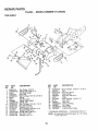
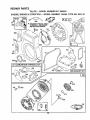
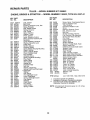
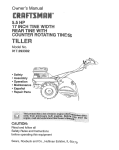
REPAIR PARTS
TILLER " " MODEL NUMBER 917.295852
HANDLES
9
\
2
15
11
KEY
NO.
1
2
3
4
5
6
7
6
9
PART
NO.
DESCRIPTION
Throttle, Control
Grip, Handle
Grommet, Handle
Bar, Drive Control Assembly
Cap, Vinyl
Panel, Control
Bushing, Sptit
* Screw, Pan Head #10-24
* Bolt, Carriage
5/16-18 UNC x 2-1/2 Gr. 5
Handle, Grip
11o646X
10
*
Clip, Hairpin
11 STD624003
Bolt, Shoulder
12 81328
Handle, Shift
11074tX
t3
Grommet, Rubber
14 109313X
Rod, Shift
110702X
t5
*
Bo_t, Carriage 3/8-16 x t Gr. 5
16 STD533710
Lock, Handle
17 109229X
127012X
141406
110673X
127254X
6712J
137119
110641X
7t 191008
STD533125
KEY
NO.
18
19
20
21
22
23
24
25
26
27
28
29
31
PART
NO.
STD541437
1913161t
109228X
150258
121145X
86777
DESCRIPTION
*Nut, Centeflock 3/6-16
Washer 13/32xl xll
Ga..
Lever, Lock, Handle
Handle, Assemble
C_ip, Plastic, Cable
Screw, Hex, Washer Hd, Slotted
#10-24 x 1/2
9484R
Clip
73970500
Locknut, Hex, Flange
110675X
Clutch, Cable
STD54t025 * Nut, Hex 1/4-20
S'TD551125 * Washer, Lock 1/4
STD541462 *Nut, Keps #I0-24
150696
Bolt, Pivot
* STANDARD HARDWARE - - PURCHASE LOCALLY
NOTE: All component dimensions given in U.S. inches.
1 inch = 25 4 mm
21
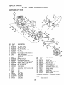
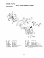
REPAIR PARTS
TILLER -- MODEL NUMBER 917.295852
MAINFRAME,
LEFT SIDE
3
I
42
38
37
17
21
20
21
KEY
NO,
PART
NO.
1
2
3
4
5
6
7
8
9
STD541431
STD551137
STD541037
74930568
STD571810
! 10111X
STD532505
8700J
86777
10
1I
12
13
14
15
16
17
19
20
21
22
23
24
25
26
27
28
15
DESCRIPTION
26
Nut, Keps 5/16-18
*Washer, Lock 3/8
*Nut, Hex 3/8-16
Bolt, Hex 5/16-18 x 4-t/4
*Pin, Roll
Lever, Shift
* Bolt, Carriage 1/4-20 x 1/2 Gr, 5
Plate, Shift Indicator
Screw, Hex, Washer Head, Slotted
#10-24 x 1/2
9484R
Clip
STD551125 *Washer, Lock 1/4
STD541025 *Nut, Hex 1/4-20
23230506
* Screw, Set, 5/16-18 x 3/8
120938X
Spacer, Split &327 x 0°42 x 2.68
STD551031 *Washer 11/32x11/16x16Ga.
145102
Sheave, Transmissien
STD541031 * Nut, Hex 5/16-18
12000028
Ring, Retainer
110653X
Guard, Pinch Point
145216
Spacer', Split 0..327 x Q.42 x 1.688
104214X
Nut, Cap 5/16-i8
5015J
Tire
128952
Rim
795R
Tire Valve
126875X
Rivet, Drilled
STD624003 *Clip, Hairpin
131159X459
Guard, Belt
132801
Belt, V
104679X
Pulley, Idler'
15
23
22
24
25
KEY
NO.
PART
NO.
29
30
31
32
33
34
35
36
37
38
39
41
42
12000032
105611X
102384X
I02141X
STD523710
102383X
74760524
102331X
130812
145822
140062
19111610
151004
*STANDARD
NOTE:
22
DESCRIPTION
Ring, Klip
Bracket, Idler
Belt, Hex 5/16-16 x 12
Shaft, Idler Arm
* Bolt, Hex 3/8-16 x 1
Ceunterweight, L.H.
Bolt, Hex 5/16-18 x 1-1t2
Bracket, Reinforcement, L.H
Sheave, Engine
Stud, Guard Belt
Cap, Plunger
Washer11/32 x 1o00 x 10 ga
Spacer, Engine
HARDWARE
-- PURCHASE
LOCALLY
All component dimensions given in U.S inches.
1 inch = 254 mm
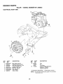
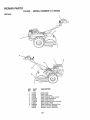
REPAIR PARTS
TILLER -- MODEL NUMBER 917.295852
MAINFRAME,
RIGHT SIDE
10
1
8
9
7
KEY
NO,
1
2
3
4
5
6
7
8
PART
NO.
STD541431
102332X
74760524
102173X
STD551137
STD541037
STD624003
t26875X
DESCRIPTION
KEY
PART
NO.
NO.
9 5015J
128952
795R
10 140535
* Nut, Keps 5/16-18
Bracket, Reinforcement
Bolt, Hex 5/16-18 x 1-1/2
Counter Weight, R.H.
* Washer, Lock 3/8
* Nut, Hex 3/8-16
* Clip, Hairpin
Rivet, Drilled
DESCRIPTION
Tire
Rim
Tire Valve
Engine, Briggs & Stratton
Model Noo 135202,
Type Noo 0237-01
* STANDARD HARDWARE - - PURCHASE LOCALLY
NOTE:
23
All component dimensions given in US.inches
1 inch = 25..4 mm
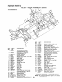
REPAIR PARTS
TILLER--IVIO1D L
NUMBER9 917.295852
TRANSMISSION
15
25
"_._
I
25
11
6
23
5
18
44
48
53
18
t
49
KEY
NO.
44
51
KEY
PART
NO.
NO.
1 150697
150698
3
4
5
6
7
8
9
10
11
12
I3
t4
15
16
18
19
20
106211X
5020J
1370H
137335
1451O1
4895H
102!36X
7392M
100371K
106!60X
142145
8353J
12000039
140525
4358J
12000040
t02114X
21
22
23
24
25
27
102115X
6803J
I02111X
STD551143
STD541143
143009
DESCRIPTION
Transmission Assembfy
(Includes Key Nos+2-52)
Gearcase, LH+ w/Bearing
(Includes Key No..4)
Gasket, Gearcase
Bearing, Needle
Washer, Thrust 5/8 x 1.10 x 1/32
Pinion, Input
Shaft, Input
Bearing, Needle
Washer, Seal
Ball, Steel
Spring, Shift, Fork
O-Ring
'
Arm, Shift
Fork, Shift
Ring, Ktip
Shaft, Shift
Washer
Ring, Klip
Gear, Assembly, Reverse Idler
(includes Key Nos+21 and 22)
Gear, Reverse Idler
Bearing, Needle
Shaft, Reverse idler
Washer, Lock 7/16
Nut, Hex 7/16-20
Bearing, Shaft, Ground Ddve L H
PART
NO+
28
29
30
3t
32
33
34
35
36
106390X
t02134X
150737
143008
106388X
102121X
102112X
102101X
137300
37
38
39
40
41
42
43
44
45
46
47
48
4422J
137301
105345X
105346X
8358J
4220R
106146X
9672R
102144X
140576
7393R
150700
49
50
51
52
53
--
132688
106147X
17720408
STD541031
122204X
6066J
DESCRIPTION
Spacer 0.765 x 1 125 x 1.23
Chain #35-50 Pitch
Ground Shaft Assembly
Bearing, Shaft, Ground Drive RH
Spacer 0.70 x 1.00 x 1 150
Sprocket and Gear Assembiy
Shaft, Reduction (2nd)
Screw, Whiz, Lock 5/16-18 x 3-1/2
Sprocket Assembty w/Bearing
(Includes Key Nos 37 and 38)
Bearing, Needle
Sprocket, Tine
Gear, Cluster, Red 1st & 2nd
Gear, Reverse
Shaft, Reduction (1 st)
Washer, Thrust
Spacer 1.01 x 1.75 x 0.760
Cup, Formed
Ring, Spiral
Seal, Ring, Rubber
Seal, Oil
Gearcase, R H.. w/Bearing
(includes Key No+8)
Shaft, Tine
Chain, Rotler #50-50 Pitch
Screw 1/4+20 x 1/2
Nut, Hex 5/16-18
Bearing Kit, Tine Shaft
Grease, Plastitube #1
* STANDARD HARDWARE - - PURCHASE LOCALLY
NOTE:
24
At] component dimensions given in US° inches.
1 inch = 25.4 mm
REPAIR PARTS
TILLER
-- MODEL
NUMBER
9'17.295852
TINE SHIELD
2
5
7
5
8
of
28
24
24
23
29
15
16
19
21
KEY
NO.
1
2
3
4
5
6
7
8
9
10
11
12
13
!4
15
16
17
PART
NO.
98000129
104088X459
8393J
12000036
STD533107
8394J
8392J
109230X
•124289X459
STD533110
STD541031
STD55113!
721 t 0510
124311 X
104101 X459
STD541025
STD551 125
DESCRIPTION
KEY
NO.
Nut, Flange 5/16-18
Shield, Side, Outer L. H.
Pin, Stake, Depth
Ring, Klip
* Bolt, Carriage 5/16-18 x 3/4 Gr 5
Spring
Bracket, Latch
Spring, Depth Stake
Shield, Tine
* Bolt, Carriage 5/16-'t8 x I Gr. 5
* Nut, Hex 5/16-18
* Washer, Lock 5/16
Bolt, Carriage 5/16-18 x 1-1/4
Bracket, Shield Tine
Shield, Side, Outer R,.H°
* Nut, Hex 1/4-20
* Washer, Lock 1/4
18
19
20
21
22
23
24
25
26
27
28
29
30
PART
NO,
DESCRIPTION
STD532512 * Bolt, Carriage 1/4-20 x 1-1/4 Gr.. 5
102701X
Grip
STD541037 * Nut, Hex 3/8-16
102156X
Stake, Depth
74930632
Bolt, Hex 3/8-16 x 2
4440J
Hinge
72140404
* Bolt, Carriage 1/4-20 x 1/4
6712J
Cap, Vinyl
109227X
Pad, ldler
102695X459
Shield, Leveling
120588X
Pin, Hinge
124309X459
Shield, Side
73970500
Locknut, Hex, Flange
* STANDARD HARDWARE - - PURCHASE LOCALLY
NOTE: All component dimensions given in U S. inches..
1 inch = 25°4 mm
25
REPAIR PARTS
TILLER -- MODEL NUMBER 917.295852
TtNE ASSEMBLY
2
1
5
3
8
11
9
\
KEY
NO.
1
2
3
4
5
6
7
PART
NO,
4459J
132673
6554J
STD624008
132727
73610600
STD551137
DESCRIPTION
KEY
NO.
Tine, Outer, Loll..
Pin, Shear
Tine, Inner, L.H.
* Clip, Hairpin
Assembly, Hub and Plate, LH.
Nut, Hex 3/8-24
* Washer, Lock 3/8
PART
NO.
DESCRIPTION
8 74610616
Bolt, Hex 3/8-24 x 1
9 4460J
Tine, Outer, R.H.
10 132728
Assembly, Hub and Plate, R..H.
11 6555J
Tine, Inner, R.H+
* STANDARD HARDWARE - - PURCHASE LOCALLY
NOTE;
26
All component dimensions given in U.S. inches,
1 inch = 25>4 mm
REPAIR PARTS
TILLER
-- MODEL
NUMBER
917.295852
DECALS
7
6
o\
KEY
NO.
I
2
3
4
5
6
7
8
9
_
--
PART
NO.
141170
152397
152400
137538
120431X
102180X
110719X
272931
120075X
153006
153007
DESCRIPTION
Decal, Logo
Decal, Logo
Decal, Description
Decal, Caution, Drive Control
Decal, Hand Placement
Decal, Shift indicator
Decal, Operation and Lubrication
Decal, Engine B&S
Decal, Warning, Rotating Tines
Manual, Owner's (English)
Manual, Owner's (Spanish)
27
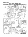
REPAIR PARTS
TILLERENGINE,
BRIGGS
- MODEL
& STRATTON
NUMBER
- - MODEL
917.295852
NUMBER
135202,
TYPE
NO. 0237-01
14
307
36
306
35
_
308
5
40
7
552
741
10
529
15
528
26
613
81
12 _
614
_ 230
(_J
_
45
27 .......
128 /i_5-.___
219 li'
22
616
_-- 59,
INSTRUCTION MANUAL.
28
REPAIR PARTS
TILLER
ENGINE,
BRIGGS
"--,_--------_L,
- - MODEL
& STRATTON
NUMBER
-- MODEL
_
\ _ _}J
917.295852
NUMBER
135202, TYPE
NO. 0237-01
679
52
/-"-_
__
205
127
392
__
435
433
124
611
967
191
916
181
621
_
224
204
223
29
REPAIR PARTS
TILLER-ENGINE,
BRIGGS
MODEL
& STRATTON
NUMBER
- - MODEL
917.295852
NUMBER
135202,
TYPE
NO. 0237-01
3°°
_r REQUIRES SPECIAL TOOLS
TO INSTALL SEE REPAIR
INSTRUCTION MANUAL.
334
23
305
200
37
52
307
7
332_
121 CARBURETOR
OVERHAUL
KIT
191
19°
[ 358 GASKET
163
%
55
30
SET
REPAIR PARTS
TILLER
ENGINE,
KEY PART
NO. NO.
1
2
3
5
7
8
9
10
1t
12
13
14
15
16
18
19
20
21
22
23
24
25
26
27
28
29
30
32
33
34
35
36
37
395990
297565
299819
214040
272157
495774
27549
94621
66578
270080
270125
27O126
94221
94679
93448
94387
492088
23O978
494044
495660
2946O6
66768
94682
94666
399673
222698
298904
298905
2989O6
298907
298982
299742
298983
298984
298985
26026
298909
298908
299430
390459
221890
94745
211119
261044
260552
26478
222443
BRIGGS
- - MODEL
& STRATTON
NUMBER
- - MODEL
917.295852
NUMBER
KEY PART
NO. NO,
DESCRIPTION
Cylinder Assembly
Bushing, Cylinder
* Seal, Oil
Head, Cylinder
* Gasket, Cylinder Head
Breather Assembly
*Gasket, Valve Cover
Screw, Breather Mounting
Grommet, Breather Tube
* Gasket, Crankcase, Standard .015"
*Gasket, Crankcase .005"Thick
*Gasket, Crankcase _009"Thick
Screw, Cylinder Head 2-3/32"
Screw, Cylinder Head 2-15/32"
Plug, Pipe, Hex Socket
Plug, Oil Drain
Crankshaft
Gear Pin, Crankshaft
Cover Assembly, Crankcase
Bushing, Crankcase Cover
* Seal, Oil
Plug, Oil Filler
Screw, Cover Mounting
Stud, Crankcase Cover
Flywheel, Magneto
Key, Flywheel
Piston Assembly, Standard Size
Piston Assembly ..010" Oversize
Piston Assembly ..020"Oversize
Piston Assembly .030" Oversize
Ring Set, Piston, Standard Size
Ring Set, Piston, Standard, Chrome
Ring Set, Piston .010" Oversize
Ring Set, Piston .020" Oversize
Ring Set, Piston .030" Oversize
Lock, Piston Pin
Pin Assembly, Piston, Standard
Pin Assembly, Piston °005" Over
Rod Assembly, Connecting
Rod Assembly, Connecting
.020" Undersize Crankpin Bore
Dipper, Connecting Rod
Screw, Connecting Rod
Valve, Exhaust
Valve, Intake
Spring, Intake Valve
Spring, Exhaust Valve
Guard, Flywheel
40
93312
45
46
52
55
56
57
58
260642
212733
272585
497442
281504
263074
280399
59 396892
60 393152
65 94686
73 225176
81 222263
90 495426
95 93499
96 223793
97 490048
108 491177
118 231533
121 495606
124 94616
127 220352
127A 223789
149 26336
152 280575
153 490589
154 93527
163 271935
!80 495391
181 494559
190 94712
190A 94677
191 272489
200 223886
201 262280
202 262270
*
**
***
135202,
TYPE
NO. 0237-01
DESCRIPTION
Retainer, Intake Valve and Exhaust
Spring
Tappet, Valve
Gear, Cam
*** Gasket, Carburetor Mounting (2)
Housing, Rewind Starter
Pulley, Rewind Starter
Spring, Rewind Starter
Rope, Rewind Starter
(Cut to Required Length)
insert, Starter Handle
Handle, Rewind Starter
Screw, Housing Mounting
Screen, Rotating
Lock, Screw
Carburetor Assembly
Screw, Throttle Valve to Shaft
Throttle, Carburetor
Shaft and Lever, Throttle
Valve and Shaft Group, Choke
Valve, Needle
Carburetor Overhaul Kit
Screw, Hex Head
Plug, Welch
Plug, Welch
Spring, Needle Valve
Spring, Throttle Adjustment
Screw and Collar
Screw, Machine, Round Head
*** Gasket, Air Cleaner Mounting
Tank Assembly, Fuel
Cap, Fuel Tank
Screw, Fuel Tank
Screw, Fuel Tank Mounting 1-3/4"
*** Gasket, Fuel Tank to Carburetor
Guide, Air
Link, Governor
Link, Throttle
Included in Gasket Set (495603)
Included in Carburetor Overhaul Kit (495606)
Included in both Gasket Set (495603), and
Carburetor Overhaul Kit (495606)
NOTE: Atl component dimensions given in U.S inches
1 inch = 25.4 mm
3'1
REPAIR PARTS
TILLER-ENGINE,
KEY PART
NO. NO.
202A 262470
203 280720
204 222962
205 231520
208 262279
209 262282
216 262359
219 494845
220 221551
222 490649
223 223455
224 93491
227
230
256
300
304
305
306
307
308
332
333
334
337
346
356
358
363
373
383
392
394
414
432
433
434
435
455
456
459
461
467
515
490374
222450
223813
393615
495759
94619
224820
94680
224738
92284
397358
93414
802592
93705
398808
495603
19069
92987
89838
262328
272650
220982
221377
93265
213963
93141
225121
281503
281505
262626
280715
263073
BRIGGS
& STRATTON
MODEL
NUMBER
- - MODEL
917.295852
NUMBER
KEY PART
NO. NO.
DESCRIPTION
Link, Control
Bell Crank
Bushing, Governor Lever, Flat
Screw, Shoulder
Rod, Speed Control
Spdng, Governor
Link, Choke
Gear, Governor'
Washer;Thrust
Panel, Control
Lever, Governor Control
Rivet, Governor Control Lever
Mounting
Lever Assembly, Governor
Washer, Governor Lever
Crank, Bell
Muffler, Exhaust
Housing, Blower
Screw, Blower Housing Mounting
Shield, Cylinder
Screw, Cylinder Shield
Cover", Cylinder Head
Nut, Flywheel
Armature Group
Screw, Armature Mounting
Plug, Spark
Screw, Sems
Wire, Ground
Gasket Set
Flywheel Puller
Nut, Hex
Wrench, Spark Plug
Spring, Fuel Pump Diaphragm
**Diaphragm
Washer
Cap, Spring
Pin, Diaphragm Cover
Cover, Diaphragm
Screw, Diaphragm Cover
Cup, Starter
Retainer'
Pawl, Starter
Pin, Spring
Knob, Control
Spring, Friction
526
527
528
529
542
552
562
592
608
611
613
614
616
621
623
634
635
676
679
680
741
851
869
870
871
9t6
966
967
968
969
971
987
995
10!2
10t6
94659
223786
231550
67838
93572
231079
92613
231082
497830
391813
93935
93306
231077
396847
94943
271853
66538
393757
270382
221839
261696
221798
211787
211172
262001
63709
280321
492797
491588
495872
490073
94018
398970
491577
490507
224278
RPM Settings:
*
**
***
135202, TYPE
NO. 0237-01
DESCRIPTION
Screw, Sems, Tank Bracket MounL
Clamp, Breather Tube
Tube, Breather
Grommet, Breather Tube
Screw
Bushing, Governor Crank
Bolt, Governor Lever
Nut, Hex
Starter Assembly, Rewind
Fuel Pipe and Clip Assembly
Screw, Hex Head, Shoulder
Pin, Cotter
Crank, Governor
Switch, Stop
Screw, Shoulder
Washer, Throttle Shaft, Foam
Elbow, Spark Plug
Deflector, Exhaust, Side Outlet
Washer, Foam
Washer, Brass
Gear, Timing
Cable Terminal, Ignition
Seat, Intake Valve, Standard
Seat, Exhaust Valve, Standard
Guide, Exhaust Valve
Guide, Intake Valve
Rack, Gear' Control
Base, Air Cleaner
Filter, Air Cleaner
Cover, Air Cleaner
Screw, Air Cleaner
Screw, Hex Head
Seal, Throttle Shaft
Lever, Bracket Assembly
Retainer, Link
Spacer
Low: 1200-1600, High: 3500-3700
Included in Gasket Set (495603)
included in Carburetor Overhaul Kit (495606)
Included in both Gasket Set (495603), and
Carburetor Overhaul Kit (495606)
NOTE: All component dimensions given in U.S. inches
1 inch = 25..4 mm
32
SE
33
LH HI _UIUll
_
..................
HH""'
.....................................
SERVICE
i illl illll
IIHIIIIllL
NOTES
34
35
illll
ii illlllllllll
iilll
illll
ii ill
£RIIFTZMIIN °
OWNER'S
MANUAL
5.0 HP
17 INCH TINE WIDTH
TINE TILLER WITH
COUNTER ROTATING
MODEL NO.
917.295852
Each tiller has its own model number,, Each engine has its own model
number.,
The model number' for your tiller will be found on a plate attached to the
top of the transmission.
The model number for your engine will be found on the blower housing of
the engine_
IF YOU NEED
REPAIR SERVICE
OR PARTS:
FOR REPAIR SERVICE, CALL
THIS TOLL FREE NUMBER:
1-800-4-REPAIR
(1-800-473-7247)
All parts listed herein may be ordered from any Sears, Roebuck and Co
Service CentedDepartment and most Retail Stores,
WHEN ORDERING REPAIR PARTS, ALWAYS GIVE THE FOLLOWING INFORMATION:
= PRODUCT - REAR TtNE TILLER
• MODEL NUMBER - 917.295852
. ENGINE MODEL NUMBER - 135202, TYPE NUMBER 0237-01
= PART NUMBER
FOR REPLACEMENT PARTS
INFORMATION AND
ORDERING, CALL THIS
TOLL FREE NUMBER:
1-800-FON-PART
(1-800-366-7278)
• PART DESCRIPTION
Your Sears merchandise has added value when you consider Sears has
service units nationwide staffed with Sears trained technicians.._ profes sional technicians specifically trained to insure that we meet our pledge
to you, we service what we sell..
Sears, Roebuck and Co., Hoffman Estates, IL 60179 U.S.A.
i
153006
1,,29.96 TR
H
PRLNTED
iN THE U,.S,,A.