1
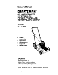
Owner's Manual
£RI:IFTSMI:IN
°
65 HORSEPOWER
22 EZ MULCH
POWER PROPELLED
ROTARY LAWN MOWER
Model No.
917.377431
•
•
•
•
•
•
Safety
Assembly
Operation
Maintenance
EspaSol
Repair Parts
CAUTION:
Read and follow all
Safety Rules and Instructions
before operating this equipment
Sears, Roebuck
and Co., Hoffman Estates, IL 60179
Warranty
Safety Rules
Assembly
Operation
Maintenance Schedule
Maintenance
2
2
4
6
10
10
Product Specifications
Service and Adjustments
Storage
Troubleshooting
Repair Parts
Parts Ordering
11
14
15
16
36
Back Cover
LIMITED "TWO YEAR WARRANTY ON CRAFTSMAN
POWER MOWER
For two years from da{e of purchase, when this Craftsman Lawn Mower is maintained,
lubricated, and tuned up according to the operating and maintenance instructions in the
owner's manual, Sears will repair free of charge any defect in material or workmanship.
If this Craftsman Lawn Mower is used for commercial or rental purposes, this warranty
applies for only 90 days from the date of purchase.
This Warranty does not cover:
• Expendable items which become worn during normal use, such as rotary mower
blades, blade adapters, belts, air cleaners and spark plug.
• Repairs necessary because of operator abuse or negligence, including bent crankshafts and the failure to maintain the equipment accordir_g to the instructions contained in the owner's manual.
Warranty service is available by retuming the Craftsman power mower to the nearest
Sears Service Center/Department
in the United States. This warranty applies only while
this product is in use in the United States.
This Warranty gives you specific legal rights, and you may also have other rights which
vary from state to state.
SEARS, ROEBUCK AND CO., D/817 WA, HOFFMAN ESTATES, ILLINOIS 60179
Safety standards require operator presence controls to minimize the risk of injury.
Your unit is equipped with such controls.
Do not attempt to defeat the function of the
operator presence controls under any
circumstances.
TRAINING:
• Read this operator's manual carefully.
Become familiar with the controls and
know how to operate your mower
properly. Learn how to, quickly stop
mower.
• Do not allow children to use your mower.
Never allow adults to use mower without
proper instructions.
• Keep the area of operation clear of all
persons, especially small children and
pets.
• Use mower only as the manufacturer
intended and as described in this manual.
• Do not operate mower if it has been
dropped or damaged in any manner.
Always have damage repaired before
using your mower.
• Do not use accessory attachments that
are not recommended by the manufacturer. Use of such attachments may be
hazardous.
• The blade tums when the engine is
running.
PREPARATION:
• Always thoroughly check the area to be
mowed and clear it of all stones, sticks,
wires, bones, and other foreign objects.
These objects will be thrown by the blade
and can cause severe injury.
• Always wear safety glasses or eye
shields when starting and while using
your mower.
•
Dross properly. Do not operate mower
when barefoot or weadng open sandals.
Wear only solid shoes with good traction
when mowing.
• Check fuel tank before starting engine.
Do not fill gas tank indoors, when the
engine is running or when the engine is
hot. Allow the engine to cool for several
minutes before filling the gas tank. Clean
off any spilled gasoline before starting the
engine.
• Always make wheel height adjustments
before starting your mower. Never
attempt to do this while the engine is
running.
• Mow only in daylight or good artificial
light.
• Do not run the engine indoors. Exhaust
fumes are dangerous.
• Never cut grass by pulling the mower
towards you. Mow across the face of
slopes, never up and down or you might
lose your footing. Do not mow excessively steep slopes. Use caution when
operating the mower on uneven terrain
or when changing directions -- maintain
good footing.
• Never operate your mower without
proper guards, plates, grass catcher or
other safety devices in place.
MAINTENANCE
AND STORAGE:
• Check the blade and the engine mounting bolts often to be sure they are
tightened properly.
• Check all bolts, nuts and screws at
OPERATION:
frequent intervals for proper tightness to
• Keep your eyes and mind on your mower
be sure mower is in safe working
and the area being cut. Do not let other
condition.
interests distract you.
• Keep all safety devices in place and
• Do not mow wet or slippery grass. Never
working.
run while operating your mower. Always
• To reduce fire hazard, keep the engine
be sure of your footing -- keep a firm
hold on the handles and walk.
free of grass, leaves or excessive grease
and oil.
• Do not put hands or feet near or under
• Check grass catcher often for deteriorarotating parts. Keep clear of the discharge
tion and wear and replace worn bags.
opening at all times.
Use only replacement bags that are
• Always stop the engine whenever you
recommended by and comply with
leave or are not using your mower, or
specifications of the manufacturer of your
before crossing driveways, walks, roads,
mower.
and any gravet--coverod areas.
• Always keep a sharp blade on your
• Never direct discharge of matedal toward
mower.
bystanders nor allow anyone near the
• Allow engine to cool before storing in any
mower while you are operating it.
enclosure.
• Before cleaning, inspecting, or repaidng
• Never store mower with fuel in the tank
your mower, stop the engine and make
inside a building where fumes may roach
absolutely sure the blade and all moving
an open flame or an ignition source such
parts have stopped. Then disconnect the
as a hot water heater, space heater,
spark plug wire and keep it away from the
clothes dryer, etc.
spark plug to prevent accidental starting.
,_CAUTION:
Always disconnect spark
• Do not continue to run your mower if you
plug
wire
and
place
wire where it cannot
hit a foreign object. Follow the procedure
contact
spark
plug
in
order to prevent
outlined above, then repair any damage
accidental
starting
when
setting up,
before restarting and operating you
transportihg,
adjusting
or
making repairs.
mower.
8
WARNING
• Do not change the governor settings or
The engine exhaust from this product
overspeed the engine. Engine damage or
contains chemicals known to the State of
personal injury may result.
California to cause cancer, birth defects,
• Do not operate your mower if it vibrates
or other reproductive harm.
abnormally. Excessive vibration is an
indication of damage; stop the engine,
safely check for the cause of vibration
and repair as required.
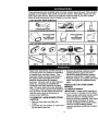
Theseaccessories
available
were available when this lawn mower was produced. They are also
at most Sears retail outlets and service centers. Most Sears stores can also
order repair parts for you, when you provide the model number of your lawn mower.
Some of these accessories may not apply to your lawn mower.
LAWN MOWER
PERFORMANCE
o
CUPPING DEFLECTOR
FOR REAR DISCHARGE LAWN MOWERS
GRASSCATCHERS
FOR
REAR DISCHARGE
LAWN MOWERS
MULCHER Krrs
_-'_/!
STABIUZER
"
GRASS CATCHERS
FOR
LAWN MOWERS
SlOE DISCHARGE
_(
GAS CANS
LAWN
MOWER
MAINTENANCE
MUFFLERS
BELTS
SPARK PLUGS
AIR RLTERS
BLADES
BLADE ADAPTERS
WHEELS
ENGINE OIL
Read these instructions and this manual in • Remove all packing materials except
its entirety before you attempt to assemble
padding between upper and lower
or operate your new lawn mower. Your
handle and padding holding operator
new lawn mower has been assembled at
presence control bar to upper handle.
• Roll lawn mower out of carton and check
the factory with the exception of those
parts left unassembled for shipping
carton thoroughly for additional loose
purposes. All parts such as nuts, washers,
parts.
bolts, etc., necessary to complete the
HOW TO SET UP YOUR LAWN
assembly have been placed in the parts
bag. To ensure safe and proper operation
MOWER
of your lawn mower, all parts and hardware TO UNFOLD HANDLE
you assemble must,be tightened securely.
IMPORTANT:
Unfold handle carefully so
as not to pinch or damage control cables.
Use the correct tools as necessary to
• Raise handles until lower handle section
ensure proper tightness.
locks into place in mowing position.
TO REMOVE
LAWN MOWER
FROM
•
Remove protective padding, raise upper
CARTON
handle section into place on lower
• Remove loose parts included with
handle and tighten both handle knobs.
mower.
• Remove handle padding holding
• Cut down two end comers of carton and
operator presence control bar to upper
lay end panel down flat.
handle.
4
•
Your lawn mower handle can be
adjusted for your mowing comfort.
Refer to "Adjust Handle" in the Service
and Adjustment section of this manual.
Operator presence controlbar
Upper handle
._Lift
J//
....
_
up_,_
,,/Lower
handle
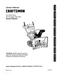
TO PREPARE
BATTERY
NOTE: Your battery must be charged
before you can start your lawn mower.
• Disconnect engine battery connector
(male) from battery connector (female)
• Connect battery charger connector
(male) to battery connector (female).
• Plug battery charger into 110 volt A.C.
outlet.
• Leave battery charger connected for 24
hours before starting your engine for the
first time.
• After charging, connect engine connector (male) to battery connector (female).
Your engine has an integral alternator for
partial charging. Connect your battery
charger to charge battery as required.
IMPORTANT: THE ENGINE
ALTERNATOR WILL NOT CHARGE A
DISCHARGED BATTERY.
At the end of the mowing season the
battery should be charged for 48 hours to
protect the battery during winter storage.
&,CAUTION: Always disconnect the
engine connector (male) from the battery
connector (female) to prevent accidental
starting when transporting or storing your
lawn mower after the season.
Battery charger
Bakery
ConNector
Engine
Connector
(male)
5
(male)
Battery
Connector
(female)
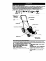
KNOW YOUR LAWN MOWER
READ THIS OWNER'S MANUALAND SAFETY RULES BEFORE OPERATING YOUR LAWN
MOWER. Compare the illustrations with your lawn mower to familiarize yourself with the
location of various controls and adiustments. Save this manual for future reference.
These symbols may appear on your lawn mower or in literature supplied with the
product.
Learn and understand
&
CAUTION
OA WARNING
ENGINE
ON
ENGINE
OFF
their meaning.
FAST
i'..I
_OW
•
CHOKE
FUEL
C_L
DANGER KEEP HANDS
AND FEET AWAY
Operator presence controlbar
Key
Engine zone
control
Auxiliar
handle
Handle knob
Gasoline fillercap
Engine oil cap with dipstick
Primer
Dnve cover
Mulcher doo
Wheel adjuster
(on each wheel)
MEETS CPSC SAFETY REQUIREMENTS
Sears rotary walk-behind power lawn mowers conform to the safety standards of the
American National Standards Institute and the U.S. Consumer Product Safety Commission. The blade turns when the engine is running.
Auxiliary starter handle - used for starting
the engine.
Drive control lever - used to engage powerpropelled forward motion of lawn mower.
Mulcher - allows conversion to discharge or
bagging operation.
Key start switch - used for starting the
engine.
Operator presence control bar- must be
held down to the handle to start the engine.
Release to stop the engine.
Pdmer- pumps additionalfuel from the
carburetor to the cylinder for use when starting
a cold engine.
6
Theoperation of any
lawn mower can result in
foreign objects thrown into the eyes, which can
result in severe eye damage. Always wear
safety glasses or eye shields while operating
your lawn mower or performing any adjustments or repairs. We recommend a wide
vision safety mask over spectacles or standard
safety glasses.
HOW TO USE YOUR LAWN MOWER
ENGINE SPEED CONTROL
°
The engine speed was set at the factory
for optimum performance. Speed is not
adjustable.
ENGINE ZONE CONTROL
A, CAU'RON: Federal regulations require an
engine controlto be installed on this lawn
mower in order to minimize the risk of blade
contact injury. Do not under any circumstances
attempt to defeat the function of the operator
control The blade turns when the engine is
running.
• Your lawn mower is equipped with an
operator presence control bar which
requires the operator to be positioned
behind the lawn mower handle to start and
operate the lawn mower.
DRIVE CONTROL
• Serf-propelling is controlled by holdingthe
operator presence control bar down to the
handle and pushing the drive control lever
forward until it dicks; then release the lever.
• Forward motion will stop when the operator
presence control bar is released. To stop
forward motion without stopping engine,
release the operator presence control bar
slightlyuntilthe drive control disengages.
Hold operator presence control bar down to
handle to continue mowing without selfpropelling.
• To keep drive control engaged when turning
comers, push down on handle and lift front
wheels off ground while tuming lawn
mower.
Operator presence control
Drive
bar _
control
__
_
To engage drive control
TO ADJUST cu'rrlNG
HEIGHT
• Raise wheels for low cut and lower wheels
for high cut.
• Adjust cutting height to suit your requiremerits. Medium pos'_ionis best for most
lawns.
• To change cutting height, squeeze adjuster
lever toward wheel. Move wheel up or
down to suit your requirements. Be sure all
wheels are in the same setting.
NOTE: Adjuster is properly positionedwhen
plate tab inserts into hole in lever. Also, 9position adjusters (if so equipped) allow lever
to be positionedbetween the plate tabs.
Lower wheels for
Plate tab
high cut
Raise wheels for low
cut
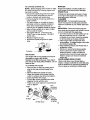
NOTE: Your lawn mower has been
shipped ready for mulching operation. To
convert to discharging operation, you must
install the discharge deflector attachment
included with your mower.
TO INSTALL DISCHARGING
DEFLECTOR
• Lift door upward on it's hinge until the
deflector frame can be hooked over the
door mounting bracket as shown.
• Release the door to rest against
deflector frame.
• To return to mulching operation, reverse
the above steps and be sure door is in
closed position.
Deflector
MulcherDoor
_._._
Mounting
Bracket
ACAUTION:
Do not operate your lawn
mower without mulcher door in closed
position, discharge deflector in place, or
approved grass catcher in place.
disengaged
7
BEFORESTARTING
ENGINE
OIL
Yourlawnmoweris shipped
without_
TO START
in the
engine.
• Be sure mower is level and area around oil
fill is clean.
• Remove angine oil cap andfiiltothefutlilne
onthe dipstick.
• Use 20 ozs. of oil. For type and grsde of oil
to use, see =ENGINE" in Maintenance
section of this maouaL
• , Pour oil slowly. Do not overfill.
• Check oil level before each use. Addeili[
needed. Fdlto fuUline on dipslk:k.
• To read proper level, tighten engine oil cap
each time.
• Reinstall engine oil cap and tighten.
• Change the oil after every 25 hours of
operation or each season. You may need
to change the oil more often under dusty,
dirty _xJitious.
GAS
• Fill fuel tank. Use fresh, ctean, regular
unleaded gasoline with a minimum of 87
octane. Do not mix oil with gasoline.
Purchase fuel in quantities that can be
used within 30 days to assure fuel
freshness.
WARNING: Expedence indicates that alcohol
blended fuels (called gaschol or using ethanol
or methanol) can attract moisture which leads
to separation and formation of acids during
storage. Acidic gas can damage the fuel
system of an engine while in storage. To avoid
engine problems, the fuel system should be
emptied before storage of 30 days or longer.
Drain the fuel tank, start the engine and let it
run unl_ fuel lines and cad_uretorare empty.
Use fresh fuel next season. See Storage
Instmcfions for adc_onel infmTnetJon.Never
use engine or carburetor cleaner products in
fuel,tank or permanent damage may occur.
Engine on cap
filler
cap
ENGINE
• To start a cold engine, push primer five
(5) times before trying to start. Use a
firm push. This step is not usueity
necessary when starting an engine
which has already run for a few minutes.
• Move engine speed control lever to fast
position.
• Hold operator presence control bar
down to the handle.
• Tum eiectdc start key clockwise to crank
engine.
IMPORTANT:
Do not crank engine more
than five continuous seconds between
each time you try to start. Wait 5 to 10
seconds between each attempt.
• TO start engine using the auxiliary
starter handle, follow the steps above.
Exchange the use Of the start key for
starter handle. Pull starter handle
quickly. Do not allow starter rope to
snap back.
• To stop engine, release operator
presence'control bar.
NOTE: In cooler weather it may be
necessary to repeat priming steps. In
warmer weather over priming may cause
flooding and engine will not start. If you do
flood engine wait a few minutes before
attempting to start and do not repeat
priming steps.
MOWING
TIPS
• Under certain conditions, such as very
tall grass, it may be necessary to raise
the height of cut to reduce pushing effort
and to keep from overloading the engine
and leaving clumps of grass clippings. It
may also be necessary to reduce
ground speed and/or run th_ lawn
mower over the area a second time.
• For extremely heavy cutting, reduce the
width of cut by overlapping previously
cut path and mow slowly.
• For better grass bagging and most
cutting conditions, the engine sp_ed
should be set in the fast position.
• For side discharge lawn mowers, cutting
in a counter-clockwise
direction, starting
at the outside of the area to be cut,
spreads grass clippings more evenly
and puts less load on the engine. To
keep clippings off of walkways, flower
beds, etc., make the first cuts in a
clockwise direction.
• Pores in cloth grass catchers can
become filled with dirt and dust with use
and catchers will collect less grass. To
prevent this, regularly hose catcher off
with water and let dry before using.
• Keep top of engine around starter clear
and clean of grass clippings and chaff.
This will help engine air flow and extend
engine life.
MULCHING MOWING TIPS
IMPORTANT: For best performance, keep
mower housing free of built-upgrass and
trash. See "Cleaning" in MAINTENANCE
section of this manual.
• The special mulching blade will recut the
grass clippings many times and reduce
them in size so that as they fell onto the
lawn they willdisperse intothe grass and
not be noticed. Also, the mulched grass will
biedegrade quickly to provide nutrientsfor
the lawn. Always mulch with your highest
engine (blade) speed as this will provide the
best recutting action of the blades.
• Avoid cutting your lawn when it is wet. Wet
grass tends to form clumps and interferes
with the mulching action. The best time to
mow your lawn is the early aftemoon. At
this time the grass has dried and the newly
cut area will not be exposed to the direct
sun.
• For best results, adjust the lawn mower
cutting height so that the lawn mower cuts
off only the top one-third of the grass blades.
If the lawn is overgrown it will be neeassary
to raise the height of cut to reduce pushing
effort and to keep from overloading the
engine and leaving clumps of mulched
grass. For extremely heavy mulching,
reduce your width of cut by overlapping
previouslycut path and mow slowly.
• Certain types of grass and grass cond_ions
may require that an area be mulched a
second time to completely hide the
dippings. When doing a second cut, mow
across or perpendicular to the firstcut path.
• Change your cutting pattern from week to
week. Mow north to south one week then
change to east to weet the next week. This
will help prevent metting and graining of the
lawn.
9
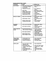
MAINTENANCE
SCHEDULE
_.,,,,,'_
_.,,,____.0_/_,:
.,/_
AS YOU COMPLETE
Check for Loose Fasteners
Clean/Inspect Grass Catcher
I_
.
l_'
If
M
(If Equipped)
Clean
Lawn Mower
i__
O
(Power-Propelled
Clean
Under DriveMowers)
Cover
Check drive belt/pulleys
E
(Power-Propelled Mowers)
I/
Check/Sharpen/Replace
Blede
Lubrication Chart
Clean Battery/Recharge
IElectrle Start MowersI
_s
I/
t/
I/4
E
N
Check Engine Oil Level
Change Engine Oil
G Clean Air Filter
I Inspect Muffler
N Clean or Replace Spark Plug
E
I_'1_1
I/2
Replace Air Filter"Paper Cartridge
I_s
1 ÷Changemo_eonefl vdlenoper_
undera heaw loadot In h_h amble_ tempe_'atur_.
2 - Servicemoreoftenwhen o_r_Ing in d_ty _ dustycondi_oos.
3 - R_4ace bladesmoreon_ v,f_enmowz_ in sandy soil.
4 - Charg_48 hoursat ind of mN_on.
GENERAL
LUBRICATION
RECOMMENDATIONS
The warranty on this lawn mower does not
cover items that have been subjected to
operator abuse or negligence, TOreceive full
value from the warranty, operator must
maintain mower as instructedin this manual.
Soma adjustments will need to be made
periodically to properly maintain your unit.
All adjustments in the Serv'_e and Adjustmerits section of this manual should be
checked at least once each season.
• Once a year, replace the spark plug, clean
or replace air filter element and check blade
for wear. A new spark plug and clean/new
air filterelement assures proper air-fuel
mixture and helps your engine run better
and last longer.
• Follow the maintenance schedule in this
manual.
BEFORE EACH USE
• Check engine oil level.
• Check for loose fasteners.
LUBRICATION
Keep unitwell lubdcated (See "LUBRICATION
CHART").
(_) Wheel
(_
CHART
Mulcher door
adjuster
oil
(_)
(_) Brake spring
bracket
bracket
mountingpin
(_)
(_)
Spray lubricante
Referto MAINTINANCE "ENGINE"
SECTION.
IMPORTANT: Do not oil or grease plastic
wheel bearings. Viscous lubricantswill attract
dust and dirt that will shorten the life of the self
lubricating bearings. If you feel they must be
lubricated, use only a dry, powdered graphite
type lubricant sparingly.
10
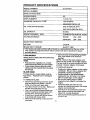
PRODUCT
SPECIFICATIONS
MODEL NUMBER
SERIAL
917.377431
NUMBER
DATE OF PURCHASE
HORSEPOWER:
6.5
DISPLACEMENT:
11.5 CU. IN.
GASOLINE
1.25 QUARTS
CAPACITY/TYP_
UNLEADED
OIL TYPE (API-SF/SG/SH):
REGULAR
SAE 30 (ABOVE 32°F)
SAE 5W-30 (BELOW 32°F)
OIL CAPACITY:
SPARK PLUG(GAP:
20 OZS.
.030")
CHAMPION
VALVECLEARANCE:
RJ19LM OR J19LM
INTAKE:
.004 - .008
EXHAUST:
.004 - .008
SOLID STATE IGNITION
l
AIR GAP:
.0125 IN.
BLADE BOLT TORQUE:
35-40 FT. LBS.
The model and serial numbers will be found on a decal attached to the rear of the
lawn mower housing.Record both serial number and date of purchase in space
provided above.
LAWN
MOWER
Always observe safety rules when performing
any maintenance.
TIRES
• Keep tires free of gasoline, oil, or insect
controlchemicals which can harm rubber.
• Avoid stumps, stones, deep ruts,sharp
objects and other hazards that may cause
tire damage.
BLADE
CARE
For best results, mower blade must be
kept sharp. Replace bent or damaged
blades.
TO REMOVE
BLADE
• Disconnect spark plug wire from spark
plug and place wire where it cannot
come in contact with spark plug.
• Turn lawn mower on its side. Make sure
air filter and carburetor are up.
• Use a wood block between blade and
mower housing to prevent blade from
turning when removing blade bolt.
• Protect your hands with gloves and/or
wrap blade with heavy cloth.
• Remove blade bolt by turn!ng counterclockwise.
• Remove blade and attaching hardware
(bolt, lock washer and hardened
washer).
NOTE: Remove the blade adapter and
check the key inside hub of blade adapter.
The key must be in good condition to work
properly. Replace adapter if damaged.
TO REPLACE
BLADE
• Position the blade adapter on the engine
crankshaft.
Be sure key in adapter and
crankshaft keyway are aligned.
• Position blade on the blade adapter
aligning the two (2) holes in the blade
with the raised lugs on the adapter.
• Be sure the trailing edge of blade
(opposite. sharp edge) is up toward the
engine.
• Install the blade bolt with the lock
washer and hardened washer into blade
adapter and crankshaft.
• Use block of wood between blade and
lawn mower housing and tighten the
blade bolt, turning clockwise.
• The recommended tightening torque is
35-40 ft. Ibs.
11
IMPORTANT:
treated.
Blade bolt is grade 8 heat
TO SHARPEN
BLADE
NOTE: We do not recommend sharpening
blade - but if you do, be sure the blade is
balanced.
Care should be taken to keep the blade
balanced. An unbalanced blade will cause
eventual damage to lawn mower or
engine.
• The blade can be sharpened with a file
or on a grinding wheel. Do not attempt
to sharpen while on the mower.
• To check blade balance, drive a nail into
a beam or wall. Leave about one inch of
the straight nail exposed. Place center
hole of blade over the head of the nail.
If blade is balanced, it should remain in
a horizontal position. If either end of the
blade moves downward, sharpen the
heavy end until the blade is balanced.
Blade
Crankshaft
Key
keyway
DRIVE WHEELS
Check front drive wheels each time before
you mow to be sure they move freely.
The wheels not turning freely means trash,
grass cuttings, etc. are in the ddve wheel
area and must be cleaned to free ddve
wheels.
If necessary to clean the ddve wheels,
check both front wheels.
• Remove hubcaps, hairpin cotters and
washers.
• Remove wheels from wheel adjusters.
• Remove any trash or grass cuttings from
inside the dust cover, pinion and/or ddve
wheel gear teeth.
• Put wheels back in place.
• If after cleaning, the drive wheels do not
turn freely, contact your nearest
authorized service center.
ENGINE"
LUBRICATION
Blade
Use only high quality detergent oil rated with
API service classificationSF, SG or SH.
Select the oil'sSAE viscositygrade according
to your expected operating temperature.
Lockwasher
\
Blade
bolt
• If lubricant is required, use only Texaco
Starplex Premium Grease, part no.
750369. Do not substitute.
shaft
Hardened
washer
Trailing
edge
Blade adapter
GRASS CATCHER
(If purchased as an accessory)
• The grass catcher may be hosed with
water, but must be dry when used.
• Check your grass catcher often for
damage or deterioration. Through
.normal use it will wear. If catcher needs
replacing, replace only with a manufacturer approved replacement catcher.
Give the lawn mower model number
when ordering.
GEAR CASE
• To keep your drive system working
properly, the gear case and area around
the drive should be kept clean and free
of trash build-up. Clean under the ddve
cover twice a season.
• The gear case is filled with lubricant to
the proper level at the factory. The only
time the lubricant needs attention is if
service has been performed on the gear
NOTE: Although multi-viscosityoils (5W30,
10W30 etc.) improve startingin cold weather,
these multi-viscosity oilswill result in increased
oil consumption when used above 32°F.
Check your engine oil level more frequentlyto
avoid possil_e engine damage from running
low on oil.
Change the oil after every 25 hours of
operation orat least once a yeaP if the lawn
mower is not used for 25 hours in one year.
Check the crankcase oil level before starting
the engine and after each five (5) hoursof
continuoususe."lighten
oilplugsecurely
each
timeyou check theoillevel.
case.
12
TO CHANGE
ENGINE
OIL
MUFFLER
Inspect and replace corroded muffler as it
could create a fire hazard and/or damage.
SPARK PLUG
NOTE: Before tipping lawn mower to drain
oil, drain fuel tank by running engine until
fuel tank is empty.
• Disconnect spark plug wire from spark
plug and place wire where it cannot
come in contact with spark plug.
• Remove engine oil cap; lay aside on a
clean surface.
°
• Tip lawn mower on its side as shown
and drain oil into a suitable container.
Rock lawn mower back and forth to
Change your spark plug each year to make
your engine start easier and run better. Set
spark plug gap at .030 inch.
CLEANING
IMPORTANT: For best performance, kiip
mower housing free of built-grass and trash.
Clean the underside of your mower after each
use.
remove any oil trapped inside of engine.
• Wipe off any spilled oil on lawn mower
and on side of engine.
• Fill engine with oil. Fill only to the
"FULL" line on the dipstick. DO NOT
OVER FILL.
• Replace engine oil cap.
• Reconnect spark plug wire to spark
plug.
ACAUTION:
Disconnect spark plug wire
from spark plug and place wire where it cannot
come in contact with the spark plug.
•Tum lawn mower on its side. Make sure air
filter and carburetor are up. Clean the
underside of your lawn mower by scraping
to remove build-up of grass and trash.
• Clean engine often to keep trash from
accumulating. A clogged engine runs hotter
and shortens engine life.
• Keep finished surfaces and wheals free of
all gasoline, oil,etc.
• We do not recommend using a garden
hose to clean lawn mower unless the
electrical system, muffler, air filter and
carburetor are covered to keep water out.
Water in engine can result in shortened
engine life.
CLEAN UNDER DRIVE COVER
Container
AIR FILTER
Your engine will not run properly and may be
damaged by using a dirty air filter.
Replace the air filter every year, more often if
you mow in very dusty, dirty conditions. Do not
wash air filter.
Clean under drive cover at least twice a
season. Scrape underside of cover with putty
knife or similar tool to remove any build-up of
trash or grass on underside of drive cover.
TO CHANGE AIR FILTER
• Remove the air filter by turning clockwise to the stop and pull away from
collar.
• Remove filter from inside of cover.
• Clean the inside of the cover and the
collar to remove any dirt accumulation.
• Insert new filter into cover.
• Put air filter cover and filter into collar
aligning the tab with the slot.
• Push in on cover arid turn counterclockwise to tighten.
Collar
Clip
Slot
Air filter
Tum
clockwise
remove
Turn
Tab
clockwise
Air filter cover
to tighten
13
A, CAUTION:
Before performing any
service and adjustments:
•
Release control bar and stop engine.
•
Make sure the blade and all moving
parts have completely stopped.
•
Disconnect spark plug wire from spark
plug and place where it _annct come
in contact with plug.
LAWN MOWER
TO ADJUST
CUTTING
HEIGHT
See "TO ADJUST CUTTING HEIGHT" in
the Operation section of this maqual.
DISCHARGE GUARD
The discharge guard, attached to the
discharge opening of your lawn mower, is
provided to prevent the possibility of injury
resulting from objects being thrown out of
the discharge opening into the operator
mowing position. If the discharge guard
becomes damaged, it should be replaced.
REAR DEFLECTOR
The rear deflector, attached between the
rear wheels of your mower, is provided to
minimize the possibility that objects will be
thrown out of the rear of the mower into
the operator mowing position. If the
deflector becomes damaged, it should be
replaced.
TO REMOVE/REPLACE
DRIVE BELT
i
•
•
•
•
•
pushing down on gear case pulley and
emove
cover. Remove belt by
rolling
beltdrive
off it.
Turn lawn mower on its side with
carburetor and fuel cap up.
Remove blade.
Remove debris shield.
Remove belt from engine pulley on
crankshaft.
Install new belt by reversing above
steps.
Always use factory approved belt to
assure fit and long life.
• To change from medium low to medium
high position, the upper and lower
handle sections will have to be turned
over.
• Remove the cable clips.
• Remove the controls and operator
presence control bar from the upper
handle.
• Remove trimplate from lower handle.
• Remove hairpin cotters,
• Disconnect the lower handle from the
handle brackets.
• Turn the handle over and reassemble
the hairpin cotters that have been
removed,
• Route cable(s) below crossbar of lower
handle and reassemble the controls and
the operator presence control bar to the
upper handle.
•,CAUTION:
The operator presence
control bar must pivot freely to permit
blade/brake engagement when control bar
is released. Do not overtighten the
fasteners holding the controls to the
upper handle.
• Reassemble trimplate to lower handle.
• To change from medium low to high
position only the upper handle section
will have to be turned over.
• To change from medium low to low
position, only the lower handle section
will have to be turned over.
ShippingPosition
Medium low
\
Drive
cover
Push
down
TO ADJUST
Medium high
High
Low
HANDLE
Your lawn mower handle can be raised or
lowered for your mowing comfort. Four
(4) positions are available: high, medium
high, medium low and low. Handles are
shipped mounted in the medium low
position.
14
IMPORTANT:
Never tamper with the
engine governor, which is factory set for
Squeeze to
the proper engine speed. Overspeeding
remove
the engine above the factory high speed
Mounting scan be dangerous. If you think the
Pin
engine-governed high speed needs
Hairpin cotter
adjusting, contact your nearest authorized
service center, which has proper equipENGINE
ment and experience to make any
ENGINE SPEED
necessary adjustments.
CARBURETOR
Your engine speed has been factory set.
Do not attempt to increase engine speed
Your carburetor has a non-adjustable fixed
or it may result in personal injury. If you
main jet for mixture control. If your engine
believe that engine is running too fast or
does not operate properly due to sustoo slow, take your mower to an authorized
pected carburetor problems, take your
lawn mower to an authorized service
service center for repair and adjustment.
center for repair and/or adjustment.
Lower handle
Handle bracket
Immediately prepare your lawn mower for
storage at the end of the season or if the unit
will not be used for 30 days or more.
Lower handle
Squeeze to
remove
LAWN MOWER
When lawn mower is to be stored for a period
of time, clean itthoroughly, remove all dirt,
grease, leaves, etc. Store in a clean, dry area.
• Clean entire lawn mower (See "CLEANING"
in the Maintenance section of this manual).
• Lubricate as shown in the Maintenance
section of this manual.
• Be sure that all nuts, bolts, screws, and pins
are securely fastened. Inspect moving
parts for damage, breakage and wear.
Replace if necessary.
• Touch up all rusted or chipped paint
surfaces; sand lightlybefore painting.
./I
Hairpin
cotter
Operator presence control
Upper handle
bar
Fold forward for
(_
storage
_
HANDLE
You can fold your lawn mower handle for
storage.
• Squeeze the bottom ends of the lower
handle toward each other untilthe lower
handle dears the handle bracket, then
move handle forward.
• Loosen upper handle mounting belts
enough to allow upper handle to be folded
back.
IMPORTANT: When folding the handle for
storage or transportation, be sure to fold the
handle as shown or you may damage the
control cables.
• When setting up your handle from the
storage position,the lower handle will
automatically lock intothe mowing position.
Lower handle
ENGINE
FUEL SYSTEM
IMPORTANT: It is important to prevent gum
deposits from forming in essential fuel system
parts such as carburetor, fuel filter, fuel hose,
or tank during storage. Also, experience
indicates that alcohol blended fuels (called
gasohol or using ethanol or methanol) can
attract moisture which leads to separation and
formation of acids during storage. Acidic gas
can damage the fuel system of an engine
while in storage.
15
•
Drain the fuel tank.
• Start the engine and let it run until the fuel
lines and carburetor are empty.
• Never use engine or carburetor cleaner
products in the fuel tank or permanent
damage may occur.
• Use fresh fuel next season.
NOTE: Fuel stabilizer is an acceptable
aitemative in minimizing the,formation of fuel
gum deposits during storage. Add stabilizer to
gasoline in fuel tank or storage container.
Always follow the mix ratio found on stabilizer
container. Run engine at least 10 minutes
after adding stabilizer to allow the stabilizer to
reach the carburetor Do not drain the gas
tank and carburetor if using fuel stabilizer.
ENGINE OIL
Drain oil (with engine warm) and replace with
clean engine oil. (See "ENGINE" in the
Maintenance section of this manual).
CYUNDER
• Remove spark plug.
• Pour one ounce (29 ml) of oil through spark
plug hole into cylinder.
• Pull starter handle slowly a few times to
distribute oil.
• Replace with new spark plug.
TROUBLESHOOTING
PROBLEM
Does not start
BATTERY
Disconnect the battery from the engine
connector and charge battery 48 hours.
OTHER
• Do not store gasoline from one season to
another.
• Replace your gasoline can if your can starts
to rust. Rust and/or dirtin your gasoline will
cause problems.
• If possible, store your unit indoors and cover
it to give protection from dust and dirt.
• Cover your unitwith a suitable protective
cover that does not retain moisture. Do not
use plastic. Plastic cannot breathe which
allows condensation to form and will cause
your unit to rust.
IMPORTANT:
Never cover mowerwhile
engine and exhaust areas are still warm.
ACAUTION:
Never store the lawn
mower with gasoline in the tank inside a
building where fumes may reach an open
flame or spark. Allow the engine to cool
before storing in any enclosure.
CHART
CAUSE
CORRECTION
• Dirty air fi_er.
• Out of fuel.
• Stale fuel.
• Clean/replace air rifler.
• Fill fuel tank.
• Drain tank and refillwith
fresh clean fuel.
• Drain fuel tank and
carburetor and refill tank
• Water in fuel.
with fresh gasoline.
• Connect wire to plug.
• Spark plug wire is
disconnected.
• Bad spark plug.
• Loose blade or broken blade
adapter.
• Control bar in released
position.
• Control bar defective.
16
• Replace spark plug.
• Tighten blade bolt or
replace blade adapter,
• Depress control bar to
handle.
• Replace control bar.
TROUBLESHOOTING
CHART
PROBLEM
CAUSE
CORRECTION
Loss of power
• Rear of lawn mower housing
or cutting blade dragging
in heavy grass
• Cutting too much grass
• Set to "Higher Cut"
position.
• Dirty air filter.
• Buildup of grass, leaves,
Poor cut- uneven
and trash under.mower.
• Too much oil in engine.
• Walking speed too fast
housing.
• Check oil level.
• Worn, bent or loose blade.
• Replace blade. Tighten
blade bolt.
• Set all wheels at same
• Wheel heights uneven.
• Buildup of grass, leaves
and trash under mower.
Excessive
vibration
• Worn, bent or loose blade.
• Bent engine crankshaft.
Starter rope hard
to pull
• Set to "Higher Cut"
position.
• Clean/replace air ltfler.
• Clean underside of mower
• Engine flywheel brake is on
when controlbar is released.
• Bent engine crankshaft.
• Cut at slower walking
speed.
height
• Clean underside of
mower housing.
• Replace blade. Tighten
blade bolt.
• Contact an authorized
se_4ce center.
• Depress controlbarto
upper handle before
pullingstarter rope
• Contact an authorized
service center.
• Blade adapter broken.
• Blade dragging in grass.
• Replace blade adapter.
• Move lawn mower to cut
grass orto hard surface
Grass catcher
not filling (if so
equipped)
Hardtopush
• Cutting height too low.
• Lift on blade wom oft.
• Catcher not venting air.
• Raise cuttingheight.
• Replace blade.
• Clean grass catcher.
• Grass istoo high or wheel
height is too low.
• Rear of lawn mower
• Raise cutting height.
housing or blade dragging
in grass.
• Grass catcher too full.
housing one (1) setting
higher.
• Empty grass catcher
• Adjust handle height to
suit
• Handle height position not
right for you.
17
• Raise rear of lawn mower
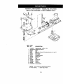
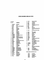
35
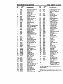
ROTARY
LAWN MOWER - - MODEL NO. 917.377431
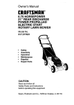
GEAR CASE ASSEMBLY
PART NUMBER
702511
7
17
15
I
KEY
NO.
1
2
3
4
6
7
8
9
10
11
12
13_
14
15
15
17
18
19
PART
NO,
DESCRIPTION
17490416
137055X004
137053
57072
Tapping Screw 1/4-20 x 1-1/4
Engagement Bracket
Shifter
Seal
48373
77881
137051
137074
57079
131484
700343
86447
137050
750435X
750369
12000003
850848
91585X004
Gear Case Halves Kit (Includes Key Nos. 4, 6, and 7)
Bearing
Worm Shaft
Drive Shaft
Hardened Washer
Clutch Yoke
Bushing
Plug
Hetical Gear
Clutch Jaw
Grease
E-Fling
Hi-Pro Key
Spring Bracket
NOTE:
All component dimensions given
in U.S. inches,
1 inch = 25.4 mm
36
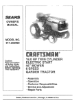
ROTARY
LAWN MOWER - - MODEL NO. 917.377431
BATTERY
ASSEMBLY
3
4
2
5
1
KEY
NO.
1
2
3
4
5
PART
NO.
DESCRIPTION
87297X479
750909
111549X
86649
134861
BatteryBracket
Battery
Battery Charger
Battery Pad
BatteryWrap
37
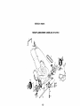
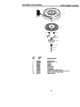
REPAIR
ROTARY
PARTS
LAWN MOWER - MODEL NO. 917.377431
4
68
72
74
4O
26
25
35
4O
39
71
38
ROTARY
KEY
NO.
1
2
3
4
5
6
7
8
9
10
11
12
16
17
18
19
20
22
23
24
25
26
27
28
29
30
31
32
33
35
36
38
39
40
41
42
PART
NO
165451X479
144929
161808
36953
132001
85529
131959
66426
51793
136376
88348
152653X479
STD512505
165175X479
151667X479
151665X479
87295
140540
750097
87584X004
151889
152904
147286
154132
152124
751592
700168X479
700166X479
STD523707
750085X007
146630
700331X004
701037
750913X004
61651
142748
LAWN MOWER - MODEL NO. 917.377431
43
44
45
151138
57143
83923
Upper Handle
Screw
Zone ControlAsm. (IncludingCable)
Screw
Rope Guide
NylonBushing
Handle Bolt
Wire tie
HairpinCotter
Handle Knob
Flat Washer 3/8
Lower Handle
Hex Tapping Screw 1/4-20 x 1/2
Support Rod
Handle BracketAssembly(Left)
Handle BracketAssembly(Right)
Trim Plate
Rear Deflector
Hex Washer Head Screw #10-24 x 1/2
DeflectorBracket
46
48
49
50
51
52
85463
149741
63601
85825
134612
150406
53
851084
54
55
56
57
58
59
60
850263
851074
152202
851514
752118
751399
74180410
62
63
64
68
156516
85543
87677
......
DischargeGuard
Decal, MulchingDoor
Hinge Rod
HousingBracket
TorsionSpring
Locknut
69
70
71
72
73
63601
151440
.....
SupportBracket(Left)
SupportBracket(Right)
Hex Head Bolt3/8-16x3/4
Wheel AdjustingBracket
Spacer
SelectorSpring
SelectorKnob
Axle Arm Assembly
BellevilleWasher
ShoulderBolt
74
169808
---
161058
166938
DESCRIPTION
153350X479
,153282X479
Wheel & Tire Assembly
Wave Washer
Locknut3/18-16
Danger Decal
Thread Cutting Screw 5/16-18 x 3/4
Hex Locknut
Screw
Debris Shield
Hex Head Thread RollingScrew 3/8-16
x 1-1/8
Hex Head Screw 3/8-24 :_1-3/8 (Grd.
6)
Helical Lockwasher
Hardened Washer
Blade 22"
Blade Adapter
Deflector
Bracket, Deflector
screw 1/4-20
Lawn Mower Housing (Incl, Ref. #46)
Engine Pulley
Hi-Pro Key #HP 505
Engine- (See Breakdown)Craftsman
Model 143.996504
SupportBrkt Handle RH
SupportBrkt Handle LH
LocknutKeps
Hubcap
Battery Assembly(See Battery Repair
Parts Page)
Zone ControlCable
Warning Decal(Not Shown)
Owner's Manual (English/Spanish)
Available accessories not included with lawn mower:
71 33072
71 33623
71 33500
71 33300
71 33316
Grass Catcher
Gas Can (2.5 gal.)
Fuel Stabilizer
SAE 30W Oil (20 oz.)
Mower Cover
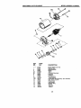
REPAIR
PARTS
ROTARY LAWN MOWER - MODEL NO. 917.377431
21
24
21
23
22
40
ROTARY
KEY
NO.
1
2
4
5
6
9
12
15
18
19
21
22
23
24
26
28
29
30
32
36
37
39
41
42
43
44
45
LAWN MOWER - MODEL NO. 917.377431
PART
NO
DESCRIPTION
145793
STD541425
158755
146323
146527
150495
751152
701037
88118
67725
88080
137054
12000058
150340
145212
150182
166732
143603
154990
132010
137052
75192
137090
702511
152018
152019
86012
ControlBar
Locknut 114-20
Hex Washer Head Screw #10-24 x 2-1/8
ControlCable Assembly
V-Belt
SpringRetainer
Lock.nut1/4-20
Selector Knob
Felt Washer
Washer 1/2 x 1-1/2 x .134
Dust Cover
Pinion
E-Ring
Wheel & Tire Assembly
Hex Flange Locknut
Hubcap
DriveCover decal
Pan Head Tapping Screw #10-24 x 2-3/4
DriveCover
Locknut
Drive Pulley
Spring
Spring
Gear Case Assembly(Compoete)
Wheel AdjusterAssembly(Left)
Wheel AdjusterAssembly(Right)
OriveshaftCover
41
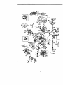
CRAFTSMAN
4-CYCLE
ENGINE
MODEL NUMBER 143.996504
347
263A
%8"E'_
--3oo
370C
262/_
110_
130
195
120
119
125
410
174
"305
1821_
178
238
250
42
CRAFTSMAN
KEY
NO.
PART
NO.
1
2
6
7
37266
26727
33734
36557
12
12A
36775
36558
12B
14
15
16
17
18
36694
28277
30589
34839A
31335
651018
19
20
30
40
36281
32600
35801
40027
40028
41
40025
4O026
42
43
45
40006
40OO7
20381
36777
46
48
50
62
69
70
32610A
27241
36778
29914
35261
34311E
72
73
75
80
91
82
30572
28833
27897
30574A
30590A
30591
83
86
89
90
92
93
100
101
103
30588A
650488
611004
611150
650815
650816
34443B
610118
651007
110
110A
110B
119
120
125
37047
36953
36954
36787
36825
37288
126
130
135
37289
6021A
35395
150
151
151A
169
172
174
31672
31673
40017
36783
36784
30200
4-CYCLE
ENGINE
DESCRIPTION
Cylinder (Incl. 2,20 & 150)
Dowel Pin
Breather Element
Breather Ass'y.
(Incl. 6 & 12A)
Breather Tube
Breather Co_er & Tube
(Incl. 12B)
Breather Tube Elbow
Washer
Governor Rod (Incl. 14)
Governor Lever
Governor Lever Clamp
Screw, Torx
"1"-15,8-32 x 19164"
Extension Spdng
Oil Sea]
Crankshaft
Piston, Pin & Ring Set (Std,)
Piston, Pin & Ring Set
(.010" OS)
Piston & Pin Ass'y. (Std,)
(Incl. 43)
Piston & pin Assay.
(.010" OS) (Incl.43)
Ring Set (Std.)
Ring Set (.010" OS)
Piston Pin Retaining Ring
Connecting Rod Ass'y.
(Incl. 46)
Connecting Rod Bolt
Valve Lifter
Camshaft (MCR)
Oil Pump Ass'y.
Mounting Flange Gasket
Mounting Flange
(Incl. 72 thru 83,306)
Oil Drain Plug (Incl. 73)
Drain Plug Gasket
Oil Seal
Governor Shaft
Washer
Govemor Gear Assay.
(Incl. 81)
Govemor Spool
Screw, 1/4-20 x 1-1/4"
Flywheel Key
Flywheel
Belleville Washer
Flywheel Nut
Solid State Ignition
Spark Plug Cover
Screw, Torx %15,
10-24 x 15/16"
Ground Wire
GrourJd Wire
D.C. Starter Wire
Cylinder Head Gasket
Cylinder Head
Exhaust Valve (Std.)
(Include. 151)
Intake Valve (Std.) (incl. 151)
Screw, 5/16-18 x 1+1/2"
Resistor Spark Plug
MODEL NUMBER 143.996504
KEY
NO.
PART
NO.
178
182
184
29752
6201
26756
185
186
189
191
36785
32653
650831
36559A
195
196
207
216
223
224
238
239
241
245
250
260
261
262
263A
275
277
285
287
290
292
298
300
610973
35035
34336
33086
650451
36786
650932
34338
36919
36905
36920
36980
30200
650831
36921
36790
650988
35000A
650926
29774
26460
28763
36916
301
305
306
307
309
310
313
314
315
322
322A
325
325A
347
370A
370C
380
390
395
36246
35647
36996
35499
650562
35648
34080
650767
36952
35013
610885
35249
37152
651038
36261
37199
640174
590739
35709
400
36792B
416
36085
417
650821
900
900
-- --
----
(RJ19LM)
Valve Spring
Valve Spring Cap
Intake Valve Seal
NOTE:
590702
starter.
Valve Cover Gasket
Valve Cover
Screw. 10-24 x 9/16"
NOTE:
All component
43inches
This
engine
1 inch = 25.4
DESCRIPTION
Nut & Lock Washer, 1/4-28
Screw, 1/4-28 x 7/8"
Carburetor To Intake Pipe
Gasket
Intake Pipe
Governor Link
Screw, 1/4-20 x 1/2"
S.E. Brake Bracket
(Include. 195)
Terminal
Power Restart Switch
Throttle Link
R.P.M. Adjusting Lever
Screw, 1/4-20 x 1"
Intake Pipe Gasket
Screw, 10-32 x 49/64
Air Cleaner Gasket
Air Cleaner Collar
Air Cleaner Filter
Air Cleaner Cover
Blower Housing
Screw, 10-24 x 9/16"
Screw, 1/4-20 x 1/2"
Starter Grill
Muffler
Screw, 1/4-20 x 2-5/16"
Starter Cup
Screw, 8-32 x 21/64"
Fuel Line
Fuel Line Clamp
Screw, 10-32 x 35/64"
Fuel Tank
(Include. 292 & 301)
Fuel Cap
Oil Fill Tube
"O"-Ring
=O"-Riag
Screw, 10-32 x 1/2"
Dipstick
Spacer
Screw, 8+32 x27/64"
Alternator Coil
Connector Body
Connector Body
Spring Clip
Spring Clip
Screw, 10-32 x 51/64"
Lubrication Decal
Primer Decal
Carburetor (Incl, 184)
Rewind Starter
Electric Starter Motor
(12 Volt)
Gasket Set
(Incl. Items Marked °)
Spark Arrestor Kit
(Incl. 417)(Optional)
Screw, 10-32 x 1/2"
(Optional)
Replacement Engine NONE
Replacement S/B 750832,
order from 71-999
RPM High 2900 to 3200
could
have
been
dimensions
mrn
built
given
with
in U.S.
CRAFTSMAN 4-CYCLE ENGINE
MODEL NUMBER 143.996504
_37
?--=7
KEY
NO.
PART
NO.
1
2
4
5
6
7
16
17
18
20
20A
25
27
28,
29
30
31
35
36
36A
37
4O
44
47
48
48A
6O
640174
631615
631767
631184
631183
640070
650506
631807
651025
630766
640018
640053
631867
631024
632019
631028
631021
631022
36045A
640080
632766
632547
640175
27110A
630748
631027
631027
632760
DESCRIPTION
Carburetor(Incl. 184 of Engine PartsList)
Throttle Shaft & Lever Assembly
Throttle Return Spdng
* Dust Seal Washer
" Dust Seal (Throttle)
ThrottleShutter
* Shutter Screw
Fuel Fitting
Throttle Crack Screw/IdleSpeed Screw
Tension Spdng
Idle RestrictorScrew
Idle RestrictorScrew Cap
Roat Bowl
* Float Shaft
Roat
* Float Bowl "O" Ring
* Inlet Needle, Seat, & Clip (Incl. 31)
SpringClip
Primer Bulb/RetainerRing
Main Nozzle Tube
CarburetorTube
* =O" Ring, Main NoZzleTube
High Speed Bowl Nut
Bowl NutWasher
* Welch Plug, Idle MixtureWell
" Welch Plug, AtmosphericVent
° Welch Plug
Repair kit (Incl. Items Marked *)
44
CRAFTSMAN 4-CYCLE ENGINE
MODEL NUMBER 143.996504
12
11C
12
f
I,
3
KEY
NO.
w--
1
2
3
4A
5B
6
7
8
10A
11C
12
13
14
15
16
17
18
PART
NO.
35709
34955
3495O
34954
34949A
34953
34945
590500
35714
34947
34946
34951
34952
34948
34953
590608
DESCRIPTION
ElectricStarter (12 Volt)
Retainer Ring
Spring Retainer
Spring
Gear
Drive End Cap Ass'y.
Lock Nut
Armature
HousingAss'y.
Thrust Washer
CommutatorEnd Cap Ass'y. (Incl.brushes)
Bolt, 10-32 x 3-3/16"
PinionDriver
Cup Washer
Retainer Ring
Washer
Drive Nut
Washer
45
CRAFTSMAN 4-CYCLE ENGINE
MODEL NUMBER 143.996504
--
11
m5
Ore2
KEY
NO.
---1
2
3
4
5
6
7
8
11
12
13
PART
NO.
590702
590599A
590600
590696
590601
590697
590698
590699
590700
590703
590535
590701
4
DESCRIP_ON
Recoil Starter
SpringPin (Incl. 4)
Washer
Retainer
Washer
Brake Spring
Starter Dog
Dog Spring
Pulley& Rewind SpringAss'y
Starter HousingAss'y (40 degree grommet)
Starter Rope ( 98" X 9/64" dia.)
Starter Handle
46
CRAFTSMAN 4-CYCLE ENGINE
KEY
NO.
---3
6
7
8
11
12
13
14
PART
NO.
590739
5g0740
590616
590617
590618A
59O638
590535
590701
590760
MODEL NUMBER 143.996504
DESCRIP_ON
Rewind Starter
Retainer
Starter Dog
Dog Spdng
Pulley& Rewind SpringAss'y
Starter HousingAss'y (40 degreegrommet)
Starter Rope (Length98" x 9/64" dia.)
Starter Handle
SpringClip
47
Forthe repairor replacementpartsyou need
delivereddirectly to your home
Call 7 am - 7 pm, 7 days a week
1-800-366-PART
(1-800-366-7278)
Para ordenar piezas con entrega a
domicilio - 1-800-659-7084.
For in-house major brand repair service
Call 24 hours a day, 7 days a week
1-800-4-REPAIR
(1-800-473-7274)
Para pedir servicio de reparaci6n
domicilio - 1-800-676-5811
a
For the location of a Sears Parts and
Repair Center in your area
Call 24 hours a day, 7 days a week
1-800-488-1222
mm|mmm
mnmmmm
For information on purchasing a Sears
Maintenance Agreement or to inquire
about an existing Agreement
Call 9 am - 5 pm, Monday-Saturday
1-800-827-6655
When requesting service or ordering
parts, always provide the following
information:
• Product Type
• Model Number
SEE/ARS
• Part Number
• Part Description
America's Repazr Specialists
166938
Rev.1
05.06.99
VB
Printed in U.S.A.