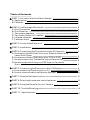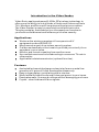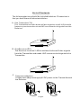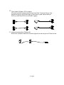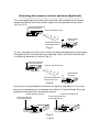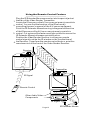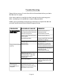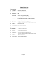
1
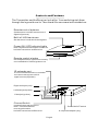
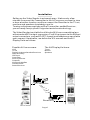
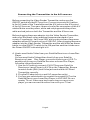
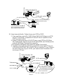
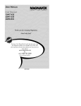
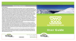
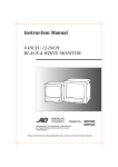
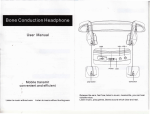
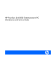
USER Manual
AWV32XL/AWV362L/AWV372L
SERIES
This equipmenthasbeentested and found to comply with the regulations
for a Class B Analog Device, pursuant tosection 15 o f t h e F C C R u l e s . This
equipment is designed toprovidereasonable protectionagainstharmful
interference inaresidential installation. This equipment generates,uses
andcan radiate radio frequency energy and, if not installed and u s e d in
accordance with the instructions, m a y c a u s e harmfulinterference to radio
communications. Due to thenatureoftheequipment, thereisnoguarantee
thatinterference will not occurin a particular installation. Ifthisequipment
dose cause harmful interference to radio or television reception, which c a n
bedetermined by turning theequipment off a n d o n , t h e u s e r i s e n c o u r a g e d
to try tocorrect the interferencebyoneormoreofthefollowingmeasures:
Rearrange o r r e l o c a t e t h e receivingantenna.
Increase theseparationbetweentheequipment and receiver.
Connect theequipmentto an outlet o n a circuit different from that to
which the receiverisconnected.
Consult thedealeroranexperiencedradio/TV technician for help.
Notice:
Changes or modifications not expressly approved by the partyresponsible
forcompliancecouldvoid the user's authority tooperatetheequipment
and place theuserinviolation of FCC regulations.
RISKOFELECTRICSHOCK
DO N O T O P E N
!
CAUTION:DONOTREMOVETHECOVER
DUETORISKOFELECTRICSHOCK.
NOUSER-SERVICEABLE PARTS INSIDE.
REFER TO QUALIFIEDSERVICE PERSONNEL FOR REPAIR ORSERVICE.
Donotexpose this product to rain o r a d a m p e n v i r o n m e n t a s t h i s m a y
create a risk offireorelectricshock as well as cause damage to this
product.
1.ReadtheInstructions:All the safety and operating instructions should
bereadbefore theproductisoperated.
2.RetainInstructions:Thesafetyandoperatinginstructionsshouldbe
kept for future reference.
3.Heedwarnings: All warnings ontheproduct andintheoperating
instructionsshouldbeadheredto.
4.Follow Instructions: All operatinganduseinstructions should be
followed.
5.Cleaning:Unplugthis product from the wall outlet beforecleaning. Do
notuseliquidcleanersor aerosolcleaners. Use a d a m p c l o t h f o r
cleaning. Donotimmerse inwater.
6.Attachments:Donot use attachments not recommended b y t h e
productmanufacturer as theymaycreatehazardousconditions.
7.Water andMoisture:Do not use this productnearwater-for example,
d o n o t u s e : n e a r a b a t h t u b ; w a s h b o w l ; k i t c h e n sink; laundry tub;
inawetbasement; near a swimmingpool; and the like.
8.
Accessories: Do n o t p l a c e this product on an unstablecart,stand,
tripod, bracket, or table. The product may fall,causing serious
injury to a child o r a d u l t a n d s e r i o u s d a m a g e t o t h e p r o d u c t . Use only
with a cart, stand, tripod, bracket, or table recommended b y t h e
manufacturer, or sold with theproduct. Any mountingoftheproduct
should follow the manufacturer's instructions, and should use a
mounting accessoryrecommendedbythemanufacturer.
9. A product andcart combination should be moved withcare. Quick
stops,excessive forceandunevensurfacesmaycausethe
product a n d c a r t combination overturn.
10. Ventilation: Slots and openings inthecabinetareprovidedfor
ventilation a n d t o e n s u r e reliable operation of the p r o d u c t a n d t o
protectitfromoverheating. Theseopenings mustnotbeblocked
orcovered.Theopeningsshould never beblockedbyplacing the
product o n a bed, sofa, rug,orothersimilar surface. This product
shouldnotbeplacedinabuilt-ininstallationsuchasabookcase
orrackunlessproper ventilation is provided and the manufacturer's
instructions havebeenadheredto.
11. PowerSources: This product s h o u l d b e operated only with the
type of power source (i.e.voltage)indicated onthemarking label.
If you a r e n o t s u r e o f t h e t y p e o f p o w e r s u p p l i e d t o y o u r h o m e ,
consult your product dealeror local PowerCompany. For products
intended tooperate from battery power, orother sources, refer to
theoperatinginstructions.
12. Power-Cordprotection: Power supply cordsshouldberoutedso
that they are not likely to b e w a l k e d on orpinchedbyitemsplaced
upon or against them, payingparticularattentionto cords atplugs,
convenience receptacles, a n d t h e p o i n t w h e r e t h e y exit f r o m t h e
product.
13. Lightning: F o r a d d e d protection for this product duringelectrical
storms, orwhen it is left unattendedandunusedforlongperiods
oftime, unplugitfromthewalloutletanddisconnect the antenna
orcable system.Thiswillpreventdamagetotheproduct due to
lightning or power-linesurges.
14. Overloading: Do not overload wall outlets, extensioncords,or
integralconvenience receptacles as this c a n r e s u l t i n a r i s k o f f i r e
orelectricshock.
15. ObjectandLiquidEntry:Neverpush objects of any kindintothis
productthrough openings as they may touch dangerousvoltage
points or short-out parts that could result i n a f i r e or electricshock.
Never spillliquid of any kindontheproduct.
16. Servicing: Do not attempttoservicethisproduct yourself as opening
orremovingcoversmayexposeyoutodangerousvoltage or other
hazards. Refer all repair orotherservicetoqualifiedservice personnel.
17. Damage Requiring Service: Unplug this product from the wall
outlet and refer servicing toqualifiedservice personnel under the
followingconditions:
If the power-supply c o r d o r p l u g i s d a m a g e d .
If liquidhasbeenspilled/upon, orobjectshave falleninto, the product.
If the product has beenexposed to rainorwater.
If the product does notoperate normally w h e n following the operating
instructions. Adjustonlythosecontrolsthatarecoveredbythe
operatinginstructions, as animproper adjustmentofothercontrols
may resultindamageandwilloftenrequire extensive work by a
qualified technician to restore the product toitsnormal operation.
If the product has beendroppedordamaged in anyway,and
When theproductexhibits a distinct change in performance, a s t h i s
indicates a need for service.
18.Heat:Theproduct should be situated away from heatsourcessuchas
radiators, heat registers,stoves,orotherproductsthatproduceheat,
includingamplifiers,electriclightsandopen fireplaces. Avoid
directsunlight.
Table of Contents
PART1:IntroductiontotheVideo Sender
A. Applications
B. Features
1
1
1
PART2:ListPackagedContents
A. One Transmitter
B. One Receiver
C.Two power adapters
D.Two Audio/Video (A/V) cables
E. Infrared extender
F. Fastener strips
2
2
2
2
3
3
3
PART3:ControlsandFeatures
4
PART4:Installation
5
PART5:ConnectingtheTransmitterto the A/Vsources
A. How to s e n d Audio/Video from your Satellite Receiver or
Laser Disc Player
B. How to s e n d Audio/Video from your VCR or DVD
C . H o w t o c o n n e c t the Transmitter toyourCamcorder
D.HowtosendAudiofromyourCDPlayerorCassette
Deck
6
PART6:ConnectingtheReceiverto the A/VDisplays
A. How connect the Receiver to y o u r T V
B. How to receive Audio o n a R e m o t e Speaker
9
10
10
PART7:ChannelSwitchselection
11
PART8:Orientingtheremote control antenna
12
PART9:UsingtheRemoteControl Feature
13
PART10:TroubleShooting
14
PART 11: Specifications
15
6
7
8
8
Introduction to the Video Sender
Video Sonic applies advanced2.4GHz RFwireless technology to
offerusers the ability tolink all kinds of Audio and Video sources to
TVs, Monitors,andPersonalComputerswithoutwiresor cables.
The Video Sender is easy tocompletelyinstallwithinminutes.
This plug-andplay featurehelps you to expandyourfreedomin
yourhome entertainment and enhance y o u r h o m e security.
Applications
Works as the wireless remoteunit forexpensiveA/V
equipment such a s I R D & D V D
May beused as part of a w ireless securitysystem.
Can b e u s e d a s a b a b y s i t t e r t o w a t c h y o u r b a b y c o n s t a n t l y f r o m
anywhere inyour home.
Monitor and record a meeting from another room.
Use multiplereceiversforbroadcastingto numerous TV sets in
otherrooms.
Applicable todatatransmission (optional function).
Features
4selectablechannelshelppreventanyinterference andallow
operation of 4 pairs ofVideo Senderssimultaneously.
Easy<plugandplay>installationwithin minutes.
Works withallkindsofAudioandVideoequipment inyour home.
Penetrates walls,floorsand ceilings without damagingyourhome.
Crystal - clear Audio a n d V i d e o signals.
Page1
List of Contents
The followingdevices should be included i n t h e b o x . P l e a s e c h e c k
that you have them all beforeinstallation.
A. One Transmitter ( T X )
The Transmitter e m i t s A u d i o a n d V i d e o s i g n a l s o v e r a 2 . 4 G H z r a d i o
frequency carrier a n d r e c e i v e s U H F r e m o t e c o n t r o l s i g n a l s f r o m t h e
Receiver.
B. OneReceiver(RX)
The Receiver receives 2.4GHz wireless Audio a n d V i d e o signals
from the Transmitter and sends UHF remotecontrolsignalstothe
Transmitter.
C. Twopoweradapters
Thesepoweradapterssupply9V DC power to the Transmitterand
the Receiver.
Page2
D. Two Audio/Video (A/V) cables
These twocables areusedtoconnecttheTransmitteror the
Receiver toyourA/Vdevices.Customerscan select either
RCA-to-RCAor RCA-to-SCART types.
E. Infrared extender (Optional)
Emits an infrared remote control signal tocontrolyourA/Vdevices.
Page3
Controls and Features
The Transmitter andtheReceiver look alike. Youcandistinguish them
through the logoontheunits.Theotherdifferencesareindicatedbelow:
Remotecontrol antenna
SendsorreceivesUHFremotecontrol
Signals(Optional)
Built in2.4GHzantenna
SendsorreceivesAudio/Videosignals.
Power ON / OFFindicatorlights
Note: M u s t b e s e t t o t h e s a m e n u m b e r o n
boththeTransmitter andReceiver
Remote control window
Infraredpassesthroughheretoremotely
controltheAudio/Videosignalsource.
IR extender port
Connectstotheremoteline-extender
mousetoremotelycontrolA/V
signal sources(Optional)
Right Audiojack(red)
LeftAudiojack(white)
Videojack(yellow)
ChannelSwitch
Usedtofindoptimalreception.
Note: Thesamechannel
mustbyselectedon
boththeTransmitterandReceiver.
PowerON/OFFswitch
9-voltpoweradapter plug
Page4
Installation
Setting up the Video Sender is extremely easy. It takes only a few
minutes toconnect the Transmitter to the A/V sources you want to view
or hear at anther location, a n d t h e n connect the Receiver to the TV set,
monitors and speakers located a t y o u r s i t e .
Turning onthepowerswitchesoftheTransmitter andtheReceiver,
you are ready toenjoytheA/Vsignalsviawirelesstechnology.
The VideoSenderissuitableforallkindsofA/Vsourcesanddisplays
withstandardRCA output connectors.ForA/Vequipmentwith different
output connectors, suchasSCART,theoptionaladaptersareavailable
upon request. Hereinafter, we define the A/V sources a n d t h e A / V
Display Units as follows:
Possible A/Vsourcesare:
The A/VDisplayUnitsare:
VCR
TV set
Digital/ AnalogueSatelliteReceivers
LaserDiscPlay
CDPlayer
Camcorder
SecurityCamera
Computer
WirelessCableBox
CassetteDeck
StereoReceiver
TV set
Monitor
Speakers
Transmitter
Receiver
Page5
Connecting the Transmitter to the A/V sources
Before connecting the Video Sender Transmitter, m a k e sure the
ON/OFF switch i s i n t h e O F F p o s i t i o n . C o n n e c t o n e s e t o f A / V c a b l e s
to the A/V jacks of the Transmitter and the A/V jacks on the A/Voutput
of the A/V sources. T h e r e a r e three c o l o r s f o r t h e connectors o f t h e A / V
cables. M a k e sure theyellow, white and red plugsmatchtheyellow,
white and red jacks on both the Transmitter and the A/Vsources.
Before plugging thepoweradapter into the Video Sender Transmitter,
make sure the power rating matches thepowerstandardof your
country.Forexample, Italy uses 220V and youshouldhave twopower
adapters with a n A / C p o w e r r a t i n g of 230V/AC. After plugging thepower
adapter into the Video Sender Transmitter and the wall outlet as shown
below,turntheON/OFF switch to the ON position and c h e c k t o b e s u r e
the Power ON/OFFindicatorlight is lit.
A. Howto send Audio/Video from your SatelliteReceiveror LaserDisc
Player
You can send Audio/Videoeither directly from your Satellite
Receiver or Laser Disc Player, o r c o n n e c t t h e m t o y o u r V C R . T o
senddirectlyfromyour Satellite Receiver orLaser Disc Player,
followthe instructions below.
1 . U s e the A/Vcableto connect A/VOUTfromyourSatellite
Receiveror LaserPlayer to A/V IN on the Transmitter. Besure
to match Audio (R&L) a n d V i d e o j a c k s o n b o t h t h e V C R a n d
Transmitter correctly.
2 . P l u g t h e D C a d a p t e r i n t o a wall AC powerlineoutlet.
3.You may use coaxialcable to connect the coaxial O U T o n t h e
SatelliteReceiveror LaserDiscPlayer to VHF/UHF IN o n a
nearby TV set. Ifthereare two l i n e s o u t o n y o u r r e c e i v e r o r
player, y o u c a n c o n n e c t t h e o t h e r l i n e o u t t o y o u r T V s e t .
Page6
Video SenderTX
(2) To wall outlet
(1) A/V CABLE
SATELLITE RECEIVEROR
LASER DISCPLAYER
VCR
DVD
VCD
LD,etc.
A/V
OUT
TV
(3)COAXIALCABLE
Recommendedmethodfor
dual-outputcomponents
B. How to s e n d Audio / Video from your VCR or DVD
1.ConnectthecoaxialIN, CATV IN o r V H F / U H F I N o n y o u r V C R
to the TV antenna, coaxial O U T o f t h e T V S e t - t o p B o x o r t h e
CATVcoaxial outlet.
2.UseA/Vcableconnect A/V OUT from y o u r V C R t o A / V I N o n
the Transmitter. Be s u r e t o m a t c h A u d i o ( R & L ) a n d Videojacks
onboth VCR and Transmitter correctly.
3 . P l u g t h e D C a d a p t e r i n t o a wall AC power line outlet.
4 . You m a y u s e c o a x i a l c a b l e t o connect t h e c o a x i a l O U T o f y o u r
VCR to the VHF/UHF IN or CATV IN on a nearby TV set. Ifthere
are two lines out onyour VCR, you canconnect theother line
out to y o u r T V s e t .
Video Sender TX
(3) To wall outlet
TVAntenna
(2) A/V CABLE
Switch
Set-top Box
CATV Outlet
TV
(1)
VCR
DVD
VCD
LD,etc.
A/V
OUT
(4) COAXIAL CABLE
(must b e p u r c h a s e d )
Recommendedmethodfor
dual-outputVCR
Page7
C. How toconnect the Transmitter toyourCamcorder
1. Use A/V cable toconnect A/V OUT onyour camcorder toA/V
INontheTransmitter.
2. Plug the DC adapterintoa wall AC power line outlet.
Video Sender TX
(2) To wall outlet
(1)
Camcorder
D. How to s e n d Audio from your CD Player orCassetteDeck
1. Use A/V cable to c o n n e c t A / V O U T onyour CD Playeror
Cassette Deck to A/V INontheTransmitter.
2. Plug the DC adapter into a wall AC power line outlet.
Video Sender TX
(2) To wall outlet
(1)
CD PLAYER
CASSETTE DECKor CD Player
Page8
Connecting the Receiver to the A/V display Units
Beforeconnectingthe Video Receiver, makesure the ON/OFFswitch
is in the OFFposition.Connectonesetof A / V c a b l e s t o t h e A / V j a c k s
of the Receiver and to the A/V jacks o n t h e A / V i n p u t o f t h e A / V D i s p l a y
Units.TherearethreecolorsfortheconnectorsofA/Ccables. Make
sure theyellow, white and red plugsmatchtheyellow,white and red
jacks on both the transmitter andtheA/Vsourcescorrectly.
Beforepluggingthepoweradapter into the Video Receiver, make s u r e
the power ratingmatchesthepower standardofyourcountry. For
example, Italy uses 220V and youshouldhave twopoweradapterswith
an A/Cpower ratingof230V/AC. After plugging the power adapterinto
the Video Receiver and the wall outlet as shown , turn the ON/OFF
switch to the O N p o s i t i o n a n d c h e c k t o b e s u r e t h e P o w e r O N / O F F
indicatorlight is lit.
Page9
A. How toconnect the Receiver to yourTV
1. Use A/Vcable to connect A/VOUTfromtheReceiverto A/VIN
onyourTV. Be s u r e t o m a t c h Audio (R&L) andVideojackson
both the ReceiverandTV correctly.
2. Plug the DC adapter into a wall A/C powerlineoutlet.
Video Sender RX
(2) To wall outlet
(1)
TV
B. Howto receive Audio o n a R e m o t e S p e a k e r
1. Use A/V cable toconnect A/V OUT on the Receiver to A/V IN
on your speaker. Be sure to match Audio (R&L) and Video
jacks on both the Receiver and TV correctly.
2. Plug the DC adapterintoa wall A/C power lineoutlet.
Video SenderRX
(2) To wall outlet
(1)
LEET SPEAKER
RIGHT SPEAKER
Page10
Channel switch selection
The Video Sender has twooperationmodes:
1.Permanentlyset to receive a specific channel
2.Switchablebetween the selectedChannelswithin4 seconds
intervals. This feature is required, forexample, when the
Receiver is used with several radiomonitoringcameras
(scanning mode).
Channel switch (rear)
Four Channelswitches(1 to 4)forselectingthereceiver Channel.
In theexampleshown
here, Channel 2 is
activated.
ON
ON
Transmitter
Receiver
Using the receiver without the Channel switch-over
function
The same Channelmustbeselectedfortransmitting and receiving
asignal. This setting makes it possible to operate u p t o 4 s y s t e m s
independently.
Example: Transmitter sends
a signal to ReceiverviaChannel2
ON
ON
Transmitter
Receiver
Using the receiver with the Channel switch-over
function
Switches 1 to 4 a r e u s e d t o s e l e c t t h e C h a n n e l s y o u w i s h t o s w i t c h
between.
Example: Receiverswitches
between Channels 1 and Channel
2at4secondsintervals.
ON
ON
ON
Transmitter1
Transmitter2
Page11
Receiver
Orienting the remote control antenna (Optional)
For most applications, b o t h o f t h e r e m o t e control antennas should
alsobeoriented vertically with respectto the mainhousing (refer
to Fig 1 & 2)
TransmitterRemote
ControlAntenna
Audio/VideoAntenna
Receiver
Audio/Video
Antenna
Receiver Remote
ControlAntenna
Fig.1
Transmitter
If your remotecontrolfunctionisnotworking satisfactorily, first rotate
the transmitter's remotecontrol antenna (local onVideo SenderRx)
to different positions (referto Fig. 3)
Receiver Remote
ControlAntenna
Audio/VideoAntenna
Transmitter
Audio/Video
Antenna
TransmitterRemote
ControlAntenna
Fig.2
Receiver
If younotice improvedperformance,keepthis orientation. I f n o t , t h e
receiver's remotecontrol antenna (located on Video Sender Rx)can
beadjustedtooptimize the performance.
Audio/VideoAntenna
Receiver Remote
ControlAntenna
Audio/VideoAntenna
TransmitterRemote
ControlAntenna
Receiver
Transmitter
Fig.3
Page12
Using the Remote Control Feature
Plug the IR Extender Mouseconnector into i t s s p e c i a l j a c k a t
1. the s i d e of the Video Sender Transmitter.
Locate the IR sensor ontheA/Vsourceequipmentyouwishto
control. You can find thelocation o f t h e I R s e n s o r b y
2. consulting theuser's manual of the A/V source equipment.
Point the IR Extender Mousehousing inthegeneraldirection
oftheIRsensorsoftheA/Vsourceequipmentyouwishto
3. control. Cut a pieceofthefastenerstripprovided to secure the
IR Extender Mouseintheappropriatelocation.
Position the VideoSender receiver to allowyour remote
control s i g n a l t o strike the IR window on the frontbottomof
the Receiver. Toperformthe remotecontrolfeature, point t h e
4. remotecontrol at the frontof the Video Sender Receiver.
Receiver
Transmitter
IR Signal
-Remote Control
Other Audio/Video
Components
IR Signal
IR Extender Mouse
Page13
Trouble Shooting
Ifaproblem occurs, f i r s t r e f e r t o t h i s informationbefore you take
the device for repair.
Ifyou are u n a b l e t o rectify the fault using theinformationgiven
here, contactyourlocaldealer orservicespecialist.
Under nocircumstances should youattempt to repair the device
yourself,asthiswouldinvalidatetheguarantee.
PROBLEM
POSSIBLE CAUSE
REMEDY
Thetransmissionchannels
for thetransmitter/receiver
donotcorrespond.
Setthetransmission
channel onthe
transmitter/receiver
.
Thetransmissiondistance
istoo great.
Reducethedistance.
Connectingcable.
Check theEURO-AV plug
andthecinchplug.
Transmitterorreceivernot
switchedon.
Switch o n t h e
transmitter
or receiver
.
Poor picture/sound Interference.
quality
.
Movethetransmitteror
receiverafewcentimetres
Changethetransmission
channel onthe
transmitter/receiver
.
Theremotecontrol
of thesignal
sourcedoesnot
respond.
Microwave u n i t s a n d t h e
u s e o f t h e s o - c a l l e d "blue
oftheso-called
toothfunction" (W LAN)
onmobilephonesor
notebooks.
Switchthisdeviceoff.
Infra-redmodule.
Check theconnectionand
positionoftheinfra-red
module.
Awirelesstransmitterinthe Switchthisdeviceoff.
433MHzrange(e.g.a
baby-phone) isinterfering
withthetransmission.
Page14
Specification
Transmitter:
1.
Frequency
:2.4GHz-2.4835GHz
2.
Channel
:4selectablechannels
3.
Modulation
:FM
Inputlevel
:Video-1Vp-p(NTSC/PAL)
Audio-1Vp-p(NTSC)/3Vp-p(PAL)
Impedance
:Video-75ohms
Audio-600ohms(NTSC)/10Kohms(PAL)
4.
Inputport
:A/Vjack-RCAtoRCAlinejacks
A/Vjack - RCAtoSCARTlinejacks(optional)
5.
Antenna
:Builtinantenna
6.
Powersupply:DC9Vpoweradapter
Receiver
1.
Frequency
: 2.4 G H z - 2 . 4 8 3 5 G h z
2.
Channel
: 4 selectablechannels
3.
Outputport
: A/V j a c k - R C A t o R C A l i n e j a c k s
A/Vjack -RCAtoSCARTlinejacks(optional)
4.
Antenna
:Builtinantenna
5.
Powersupply
:DC9Vpoweradapter
Page15
DOC0000-0104