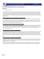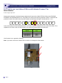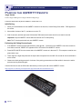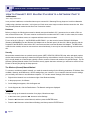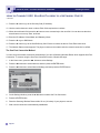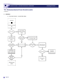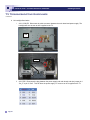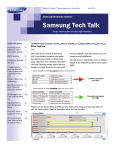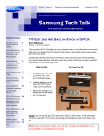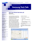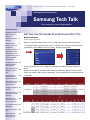
1
Volume 5, Issue 7 Consumer Electronics Newsletter July 2011 Samsung Electronics America Samsung Tech Talk Your source for service information Inside this issue: Setting the Option Byte in 2010 and 2011 TVs 1 Customer Satisfaction Quiz 3 Camera Corner: Camera Fixes and Procedures 4 Setting the Option Byte in 2010 and 2011 TVs Manuel Caballero Product Support Specialist When you replace the Main PCB on a TV, it is vital that you set the correct option byte. To access the option byte setting, go to the TV’s factory menu using your factory remote or press MUTE-1-8-2-POWER on the TV’s remote, and then select Option. No Power and the X 7 -Main PCB on 400 Series Plasma TVs, Troubleshooting the 8 2011TV 3D Bluetooth Module Troubleshooting the 11 2011TV 3D Bluetooth Glasses New Training Video 13 Released on Plus One Samsung at the Mid-Atlantic Electronics Conference 14 New TV Fast Tracks 15 Provide Critical Repair Information Pairing the QWERTY 16 Remote 2011 3D Operation 17 and Circuit Troubleshooting How to Connect 2011 Blu-ray Players to a Network 19 TV Troubleshooting 22 Guidelines 2011 RTC TV Train- 26 ing 2011 LED/LCD/ PDP Training On Line on Plus 1! 27 Once in the Option sub-menu, change the option byte according to the table posted on GSPN. Below is an example of the Option Byte Table that includes the different version for each model, part number, and the correct option byte. For the complete list, check the GSPN Service Bulletin. Volume 5, Issue 7 Consumer Electronics Newsletter Samsung Tech Talk Flat Panel Certification Privileges Are About to Expire! Technicians who obtained 2010 Flat Panel certification privileges are advised that those privileges are about to expire. If you want to continue to order warranty LCD and PDP panels without contacting Tech Support, make sure you update your certification by July 15th. 2011 Flat Panel training and the accompanying certification exam are available now at: https://my.plus1solutions.net/clientPortals/samsung/. Don’t wait. Take the training, take the exam, and update your certification today! Page 2 Volume 5, Issue 7 Consumer Electronics Newsletter Samsung Tech Talk A Customer Satisfaction Quiz Wes Sirios Assistant Manager, Triage Lead Customer Satisfaction is one of the most important components of a successful service business. Since the main product being sold is service, how that product is delivered to your customers can mean the difference between a profitable organization and one that struggles to stay afloat. Asking yourself a few important questions about your operation (and answering them honestly) on a regular basis can help you keep your business in the black. Here are a few questions to get you started: Would I want my mother to call this business to schedule service? Customer satisfaction begins with the initial call from the customer. How the people that man your phones speak with your customers is critical. A pleasant voice and a good attitude should be what the customer hears over the phone. It does not matter how uncooperative or rude a customer may be, the person taking the call should remain calm, allow the customer to vent, and offer solutions to the problem at hand. Are my office procedures conducive to customer satisfaction? Take a look at the flow of your daily processes. Make sure that all service tickets are accounted for and that customers who are waiting for parts are kept informed about the availability of the parts. A major cause for dissatisfaction is a lack of communication between the office and the customer. Parts should be ordered on a daily basis to lessen the turnaround time of service calls. Are my technicians properly dressed and groomed? A professional service organization provides its technicians with uniforms. These garments should be clean and should fit the technician properly. First impressions can make all the difference and proper attire is the first thing a customer sees when the tech arrives at the home. Along these same lines, all techs should have proper shoes and shoe covers, soft tools bags or pouches, protective mats, and any item that demonstrates the tech’s concern for the customer’s property. Do my technicians keep up their product knowledge? Online training, classroom sessions, technical support, and service manuals are available to help technicians with their daily job performance. All techs should be aware of how to access this information and should take advantage of any opportunity to enhance their knowledge. These are just a few of the questions that you should ask yourself on a regular basis. Positive answers to these questions will help ensure that your business is successful and your customers are happy with their service experiences. Page 3 Volume 5, Issue 7 Consumer Electronics Newsletter Samsung Tech Talk Camera Corner: Camera Fixes and Procedures Manuel Caballero Product Support Specialist The EC-HZ50W OIS F/W Adjustment Procedure After you have replaced the barrel or Main board of the EC-HZ50W, perform the following steps: 1. Perform an OIS firmware update a. Copy the OIS firmware file to the root of the memory card, and then insert the card into the camera. b. Turn on the camera, and then select "Yes." The OIS firmware will automatically update. 2. Perform a Gyro offset Calibration adjustment a. Unzip and open the SSISCal program, and then connect the camera to the PC. Turn on the camera. b. Press the EXE button of the SSISCal program. The Gyro offset Calibration adjustment will start automatically. 3. Write the Barcode a. Open the SSISCal program, and then press the Adj button. b. Write the barcode by using the attached QR code. New Firmware for EC-PL200 Resolves Purple Fringe Issue Under certain conditions, photos have a purplish tinge. This is caused by the lack of margin provided by the software. The red output is at the minimum value of the CCD. To resolve this issue, update to the latest firmware. However, before you download the firmware, determine whether you need the Global or USA version. Global F/W: All released cameras except American (PL20_FW_G_1102151.zip). USA F/W: Only American released cameras (PL20_FW_U_1102154.zip). For the firmware file, please check GSPN. Page 4 Volume 5, Issue 7 Consumer Electronics Newsletter Samsung Tech Talk Camera Corner: Camera Fixes and Procedures continued Fixing the EC-PL120 and EC-PL170 Zoom Operation Problem In some cases, a blurred image will appear when you turn on the camera. Also, you will see a warning message on the display that the zoom did not operate normally, as shown below. New firmware has been released which improves the zoom and focus performance of the PL120 and PL170. Before applying the firmware update, determine whether you need the Global or USA version. PL120: Global F/W: PL120_DSP_G_SR_F1105241.zip (PL120-DSP-1105241-full.elf) USA F/W: PL120_DSP_U_SR_F1105244.zip (PL120-DSP-1105244-full.elf) PL170: Global F/W: PL170_DSP_G_SR_F1105241.zip (PL170-DSP-1105241-full.elf) USA F/W: PL170_DSP_U_SR_F1105244.zip (PL170-DSP-1105244-full.elf) If the firmware update does not fix the issue, take out the motor, and then move the AF clip to the upper position: Rotate the shaft and move the AF Clip to the upright position. Page 5 Volume 5, Issue 7 Consumer Electronics Newsletter Samsung Tech Talk Camera Corner: Camera Fixes and Procedures continued New Parts Repair Process for all Digital Still Cameras Samsung recently launched a new repair process that will reduce your costs for parts. The general process is described below. 1. Partners will send all defective barrels to the refurbishing company, bi-weekly (on Friday, every other week). No need to individually wrap these products, but if possible, please label each group and label each barrel with the Model Number 2. The refurbishing company will break apart all the barrels and piece as many barrels back together as possible. 3. The refurbishing company will then send all functioning barrel assemblies back to our vendors. The exact number of functioning barrels will depend on how badly the original parts were damaged. The target for the initial launch is to return 50% of the product. This target will go up as time goes by. 4. Partners will receive these parts and use them to fix their inventory (warranty or return). For Parts Claims on GSPN and DS3C, input "FOC" in the Invoice No. field for each entry. The illustration below shows you where to input the information on GSPN. Page 6 Volume 5, Issue 7 Consumer Electronics Newsletter Samsung Tech Talk No Power and the X-Main PCB on 400 Series Plasma TVs Manuel Caballero Product Support Specialist Samsung has released an important firmware update that will prevent the X-Main PCB from failing in the PN43D440, PN43D450, and PN43D490 plasma TVs. This update is for January and February production models. To determine the production month of the model, look at the serial number and check the ninth digit. It should either be a 1 or 2. Z 3 2 R 3 C E B 1 0 0 0 1 5 N If you are servicing one of the models listed above, and it has no power, troubleshoot the root cause of the failure. Then, regardless of the cause, make sure the firmware is at or above the version listed in the chart below. Model PN43D440A1D PN43D450B1D PN43D490A1D Firmware Version 1006.6 1006.6 1013.8 If the firmware is not, upgrade the firmware. Note: If you need to remove the X-Main PCB, be careful not to damage the ribbon cables. Page 7 Volume 5, Issue 7 Consumer Electronics Newsletter Samsung Tech Talk Troubleshooting the 2011 TV 3D Bluetooth Module Chuck Russo Assistant Manager, Technical Training For its 2011 3D TVs and glasses, Samsung has changed the technology the TVs and glasses use to communicate with one other from IR to Bluetooth. This change requires new troubleshooting techniques and procedures, which are described below. To confirm Bluetooth is working on LN46D8000 (LED) and PN59D8000 (Plasma) TVs, follow these steps: 1. Turn the TV on. Bluetooth will always be active. 2. Using a cell phone with the Bluetooth option, activate Bluetooth Scan and Pairing on the cell phone. 3. Verify that “HD TV” (or a related message) appears on the cell phone, indicating that the TV is a recognized Bluetooth device in the area. 4. Turn off the TV, and then repeat the test to verify the scan was from that particular TV. If the cell phone fails to recognize the Bluetooth signal, follow these steps: 1. Check the voltages and signals at the Bluetooth Module Connector. Consult the Service Manual for the correct voltages and signals. 2. If the correct voltages and signals are present, replace the Bluetooth module. 3. If the voltages and signals are incorrect, check the Main Board signals and connector. For additional information, including the location of the Bluetooth modules and pin out information, see the illustrations on the following two pages. Page 8 Volume 5, Issue 7 Consumer Electronics Newsletter Samsung Tech Talk Troubleshooting the 2011 TV 3D Bluetooth Module continued LN46D8000 FUNCTION BOARD & ASSY BLUETOOTH Module Frame removed & inverted 224 Troubleshooting ‘Bluetooth Troubleshooting If External Cell Phone Test fails to recognize a Bluetooth Signal: Check Voltages/Signals at Connector If correct replace Bluetooth Module Incorrect check Main Board Sig/Connector BLUETOOTH Module Rear Frame removed & inverted 226 Page 9 Volume 5, Issue 7 Consumer Electronics Newsletter Samsung Tech Talk Troubleshooting the 2011 TV 3D Bluetooth Module continued PN59D8000 BLUETOOTH Module 385 Troubleshooting Bluetooth Troubleshooting ‘ If External Cell Phone Test fails to recognize a Bluetooth Signal: Check Voltages/Signals at Connector If correct replace Bluetooth Module Incorrect check Main Board Sig/Connector BLUETOOTH Module 386 Page 10 Volume 5, Issue 7 Consumer Electronics Newsletter Samsung Tech Talk Troubleshooting the 2011 3D Bluetooth Glasses Chuck Russo, Assistant Manager, Technical Training Tony Perkins, Regional Technical Trainer Samsung’s new 2011 Bluetooth 3D technology provides 2 way communications between Samsung 3D TVs and 3D Bluetooth glasses. With 2-way communication, the glasses can be activated automatically when a 3D source activates 3D TV operation. The glasses can also be activated manually by the customer. Like other Bluetooth devices such as cell phones, “Pairing” is necessary to establish a proper communications link between the specific source, the TV, and the Bluetooth device, the 3D Glasses. To pair 3D Bluetooth glasses with a Samsung 3D TV, follow the steps below. 1. Ensure that the battery in the glasses is fully charged. 2. Bring the glasses within 6 feet of the TV. 3. Press and hold the power button on the glasses until the red and green LEDs blink. This should take 2 to 3 seconds. 4. A message appears in the lower left corner of the screen if the pairing is successful. 81 Troubleshooting Bluetooth Glasses Problem: No 3D viewing Possible Causes 1. Incorrect Glasses: Ensure that Samsung 2011 3D glasses are being used (i.e. SSG-3700CR, SSG-3300CR, and SSG-3300GR). Samsung 2010 3D IR glasses are not compatible with Samsung 2011 3D Bluetooth TVs. 2. Power: Check the LEDs on the glasses and confirm that a good battery is installed correctly and that it has a full charge. 3. Pairing issue: Re-Pair: Turn the TV on, move within 2 feet of the TV, press and hold the power button on the glasses, and then look for blinking LEDs on the glasses and the On-Screen confirmation on the TV:“TV Glasses is connected to the TV”. Page 11 Volume 5, Issue 7 Consumer Electronics Newsletter Samsung Tech Talk Troubleshooting the 2011 3D Bluetooth Glasses continued If the glasses are not pairing, try another set of glasses or a Smart phone. If pairing works with another device (glasses or phone), troubleshoot the glasses. Look for a weak or discharged battery, etc. The TV is okay. 4. Confirm TV 3D operation. Use the 2D-3D conversion method. See page 15 for details. 5. Confirm the 3D signal source. Please Send Us Your Comments! Something you’d like to see in the Samsung Tech Talk Newsletter? If there a topic/issue we haven’t covered that you’d like us to write about, LET US KNOW! Please send your comments to: [email protected] Page 12 Volume 5, Issue 7 Consumer Electronics Newsletter Samsung Tech Talk New TV Training Video Released on Plus One Chuck Russo Assistant Manager, Technical Training Samsung’s new training video, 2011 Samsung TV Servicer Procedures, provides a practical example of how to repair a Samsung TV while ensuring the utmost customer satisfaction. The video demonstrates proper servicer techniques through modules that cover preparation and triage, tools and test equipment, verifying the problem, servicing the TV, final testing, and customer education. The modules are listed below. MODULE 1: Preparation and Triage This module explains the importance of preparation and customer triage and shows you what you need to do before you service a TV. MODULE 2: Mandatory Tools and Testing Equipment This module provides a list of tools and testing equipment you need to repair a TV. It also covers optional tools and testing equipment that can assist you in the repair as well as increase your efficiency. MODULE 3: Verifying the Problem This module shows both “how to” and “where to” start troubleshooting. It guides you to the source of the problem while reminding you to think simple before thinking big! MODULE 4: Servicing the TV This module shows you how to address the problem, and then steps you through the repair and the follow up alignments. It also demonstrates important inspection procedures, shows you how to redress connections and cabling, demonstrates detailed repair techniques, and provides repair tips and reminders. MODULE 5: Final Testing and TV Setup Many servicers are anxious to leave once the TV has been repaired and miss important factors that could prevent a call back or Redo. In this module, you will learn procedures that ensure full TV operation has been reestablished. MODULE 6: Customer Education It is as important to educated the customer as it is to complete the repair. This module shows you how to explain the repair to the customer and how to pass along simple troubleshooting procedures while providing reassurance that the TV is fixed and operating normally. This is a great opportunity to bring the customer to the level of “loyalty” rather than just “satisfaction”. Page 13 Volume 5, Issue 7 Consumer Electronics Newsletter Samsung Tech Talk 2011 TV Wireless Network: A T-Shooting Alternative Samsung at the Mid-Atlantic Electronics Conference continued Chuck Russo Assistant Manager, Technical Training Samsung Technical Trainers recently attended the Mid-Atlantic Electronics Conference, held from June 9th through June 11th in Virginia Beach, Virginia, and provided TV training seminars for the attendees. The TV training included detailed descriptions of the 2011 TV Products, including new features such as built in Wi-Fi and 3D Bluetooth, and explanations of how to troubleshoot the new products. A 2011 PN51D6900FXZA plasma TV was used as the demonstration model . The techs in attendance were especially appreciative of the circuit explanations and hands on troubleshooting procedures on the plasma TV as well as the Network and 3D troubleshooting. Older LCD and LED models were also covered. Above: Samsung’s Chuck Russo explains the finer points of Plasma TV operation. Page 14 Volume 5, Issue 7 Consumer Electronics Newsletter Samsung Tech Talk 2011 TV New TV Fast Wireless Tracks Network: ProvideACritical T-Shooting Repair Alternative Information continuedRusso Chuck Assistant Manager, Technical Training Samsung's new TV Fast Tracks are direct and to the point technical troubleshooting guides that provide critical parts and repair information. Available on GSPN, most Fast Tracks are just 3 to 5 pages in length plus any special bulletins. Most 2010 LCD, LED, and Plasma TVs will soon have Fast Tracks available. Visit GSPN to download the TV Fast Track for the model you are servicing. The TV Fast Tracks include: Fast Moving Parts. Specific Bulletins and Important “Hot” Servicing Tips. The latest Firmware and Option Bytes Info. Circuit Block Diagrams and Connector Pin Out Descriptions. Power Start-Up Sequences and expected voltages. Troubleshooting for Power and Video Failures. Screen Failure Examples and Necessary Alignments. Consult the TV Fast Track before you go to the customer's home, and then bring it with you on the service call to help expedite the repair and prevent REDO!! Sample Fast Track pages for the PN50C450B1DXZA are below. PN50C450B1DXZA Fast Track Troubleshooting Manual Power On Sequence ‐STBY 5V (Pin 2 CN801) ‐PS_ON (approx 3.3V – 0V) (Pin 1 CN801) ‐VS_ ON (approx 0V – 3.3V) (Pin 6 CN802) 2 Fast Track Troubleshooting Manual Fast Track Troubleshooting Manual TROUBLESHOOTING VIDEO PROBLEMS 1. Verify Video Operation a. Customer Picture Test (models available) b. “Display” (If display is OK source is suspected) C. Substitute with known good Source (external DVD or Signal Generator) 2. Using Test Patterns in Service Mode ‐ ENTERING SERVICE MODE ‐ Customer Remote Service Remote 1. Power off 1. Power On 2. Mute, 182, Power 2. Info, Test SAMPLE VIEW & READINGS 2011 PDP 8000 Series . “VITAL SIGNS” Power Supply Trouble Shooting Notes: 2010/2011 models Will not be run with the “X” or “Y” main disconnected. The SMPS will shut down immediately. However if a meter is first connected to the test point when power is applied it will read the correct voltage briefly before shut‐ ting down.(You have enough time to check key voltages) CAUTION: Do not reconnect any connectors to SMPS or Y/X Boards until power has been turned off long enough for Vs to drop below 10V or damage will occur to X or Y Boards. . Over Current Protection For the SMPS Power Supply... If a short circuit occurs on either the VS or VA voltage lines, the SMPS stops operating, but should not fail. When the short circuit is removed from the source line, the Power Supply will operate normally again. Many SMPS Supplies are replaced needlessly! 4 Page 15 When troubleshooting, It’s very important to first check Vs, Va, Vsc & Ve If Vs is missing (0V), disconnect power and check for short. Use ohm meter to measure resistance while disconnecting Y‐Board & X‐Board supply feeds one at a time. Turn Power On and Test SMPS with short connector removed for correct Vs voltage verification. (It may only come up briefly but to full level). Again be careful not to reconnect Power Connectors until Vs falls below 10V. If Va is low or missing, disconnect Supply Feed to Address Boards and Check to see if SMPS Supply is restored. (Note Va feed normally passes through the Y‐Drive to the Address Boards (Logic Buffer Boards). If Vsc is low or missing and Vs was OK, the failure is with the Y‐Board . since the Y‐Board generate the Vsc voltage from the Vs supplied by the SMPS. If Ve is low or missing and Vs is OK, the failure is with the X‐Board since the Ve is generated by the X‐Board from the Vs supplied by the SMPS. Please note in some rare cases the Ve may be generated by the Y‐Board feed to the X‐ Board.) Other SMPS Voltages: Check Low Voltage feeds to the Main Board and other supplied Assemblies. 3 Volume 5, Issue 7 Consumer Electronics Newsletter Samsung Tech Talk Pairing the QWERTY Remote Jorge Tavora Product Support Manager/Tech Support Hotline/NAHQ Triage Follow the steps below to pair the QWERTY remote with a TV: Initial Pairing 1. When you insert batteries into the QWERTY remote for the first time, “Need Pairing Press SYM + TAB” appears on the screen. 2. Move within 8 inches of the TV, and then turn on the TV. 3. Wait 30 seconds, and then press the SYM and the TAB buttons at the same time for more than 2 seconds. Important: Keep the QWERTY remote within 8 inches of the TV when pairing. Note: The TV can be paired with only one QWERTY remote. Performing the Pairing Process Again 1. If the QWERTY remote has been paired before, press @ and [ ] left arrow on the QWERTY side of the remote for more than 3 seconds. “RESET OK” appears on the LCD screen of the QWERTY remote. 2. Press MUTE-0-MUTE-0 on the remote side of the QWERTY remote as it faces the TV. This sequence must be completed within 4 sec. 3. There might be a slight delay between the input and the response from the OSD. Do not wait for visual confirmation on the screen. 4. Observe the initial pairing process for 3 minutes. If the pairing process does not finish within 3 minutes, the whole process must be performed again. Visit the link below to see an SPSN video that shows you how to pair and use the QWERTY remote. http://support-us.samsung.com/spsn/howto.jsp?channelId=201&scheduleId=4172 Page 16 Volume 5, Issue 7 Consumer Electronics Newsletter Samsung Tech Talk 2011 3D Operation and Circuit Troubleshooting Chuck Russo, Assistant Manager, Technical Training Tony Perkins, Regional Technical Trainer The Samsung 2011 3D video circuit functionality is similar to 2010 models and requires similar troubleshooting techniques. The major change is from IR to Bluetooth technology, which impacts the operation of the 3D glasses and the Main Board’s 3D circuitry and the communications between them. However, 3D video decoding, 2D-3D simulation, and various user operation selections remain similar to 2010 operation and technology. Above: 3D formats. Samsung uses the Frame Packing 3D format. In its 3D TVs, Samsung uses the Frame Packing format. Full HD resolution is maintained, with 1920 pixels horizontally and 2205 pixels vertically (1080 x 2 plus Blinking Period). The HDMI 1.4 broadcasting format utilizes both Top and Bottom (half vertical resolution) and Side by Side (half horizontal resolution) configurations. Other configurations are used for PC type operations. The Samsung circuitry will attempt to respond to various input configurations, however, in some cases the user will have to select the correct one manually. Page 17 Volume 5, Issue 7 Consumer Electronics Newsletter Samsung Tech Talk 2011 3D Operation and Circuit Troubleshooting continued 3D User Operation Selections 2D → 3D: Extracts Left and Right images artificially from normal 2D content input and shows it in 3D. (A function of the TV). 3D → 2D: When watching 3D TV from a 3D source, the viewer can change the TV into 2D mode. The TV only displays one of the Left and Right images. Depth: Only functions in the ‘2D → 3D Mode’. Increases or decreases the 3D effect. L/R Correction: Switches the position of the left and right images so that they correspond with the 3D glasses. 3D Disable: 3D Disable will turn off the 3D mode. Above: A 3D picture viewed without 3D glasses. Troubleshooting 3D Video Operation 1. Select a 2D video source. 2. Activate 2D-3D Mode in the User Menu. 3. Select and then adjust the Depth control through its range. Start at 0, with little or no 3D effect, and slide up to 10, the maximum setting value, and observe the picture. The Depth control will increase the 3D effect or double image when you view the picture without 3D glasses, as shown in the picture above. 4. If you observe the 3D effect, the 3D video circuit is operational. If you see no effect, then suspect the Main Board is defective. Page 18 Volume 5, Issue 7 Consumer Electronics Newsletter Samsung Tech Talk How to Connect 2011 Blu-Ray Players to a Network: Part 2 Jeff Brutman Senior Staff, Publications In our previous installment, we described two ways to connect 2011 Samsung Blu-ray players to Local Area Networks (LANs) using a wireless connection. In this issue, we’ll look at two more ways to make a wireless connection: the Wireless (General) Manual method and the One Foot Connection method. Hardware Before you begin, the following items must be already set up and installed: a PC, Internet service, a cable or DSL modem, and a wireless router. The router must be connected to the modem with CAT 5 cable. In some cases, the modem also functions as a wireless router, so a separate wireless router is not needed. For two of the 2011 Blu-ray’s – the BD-D5500 and BD-D5300 – you also need to insert a Wireless LAN Adapter (Samsung WIS09ABGN) into the Wireless LAN Adaptor slot on the back panel. All other 2011 Blu-ray players, with the exception of the BD-D5100, have built-in Wi-Fi connectors and don’t need the Wireless LAN Adaptor. The BD-D5100, unlike the other models, cannot be connected to a network wirelessly. It can only be connected through a wired connection. Security Most wireless networks have an optional security system (WEP, WPA-PSK, WPA2-PSK) that, when activated, requires devices that access the network to transmit an encrypted security code called an Access or Security Key. The Security Key is usually based on a Pass Phrase, typically a word or a series of letters and numbers of a specified length. For the Wireless (General) Manual method, if the network’s security system has been activated, you will need to enter the Pass Phrase or Security Key during the setup process. The Wireless (General) Manual Method To connect to a wireless network manually, you need the network settings for the following parameters: IP Address, Subnet Mask, Gateway, and DMS server. Get the settings from your customer. If your customer does not have the settings, you can easily view them on most Windows computers. To view the network settings, follow these steps: 1. Right click the Network icon on the bottom right of the Windows desktop. 2. In the pop-up menu, click Status. 3. On the dialog that appears, click the Support tab. 4. On the Support tab, click the Details button. The Network settings are displayed. First Steps To begin setting up the network connection for a player, follow these steps: 1. In the Home menu, press the ◄► buttons to select Settings. 2. Press the ▲▼ buttons to select Network, and then press the ENTER button. 3. Press the ▲▼ buttons to select Network Settings, and then press the ENTER button. Page 19 Volume 5, Issue 7 Consumer Electronics Newsletter Samsung Tech Talk How to Connect 2011 Blu-Ray Players to a Network: Part 2 continued The Wireless (General) Manual Connection Procedure To connect a Blu-ray player using the Wireless (General) Automatic procedure, follow these steps: 1. Follow Steps 1 through 3 under First Steps. 2. Press the ▲▼ buttons to select Wireless (General). 3. Press the ENTER button. The Blu-ray searches for networks. When done, it displays a list of the available wireless networks. 4. Press the ▲▼ buttons to select the desired network, and then press the ENTER button. If the network requires a password, the Security screen appears. Go to Step 5. If it does not, go to Step 7. 5. On the Security screen, have the customer enter the network’s Pass Phrase or Security Key. Enter numbers directly using the remote control. To select a letter, press the ▲▼◄► buttons to move the cursor, then press the ENTER button. 6. When finished, press the ▲▼◄► buttons to move the cursor to Done, and then press the ENTER button. The Network Status screen appears. 7. On the Network Status screen, select Cancel, and then press Enter. 8. Press the ◄► buttons to select IP Settings, and then press the ENTER button. 9. Press the ENTER button to select IP Mode. 10. Press the ▲▼ buttons to select Manual, and then press the ENTER button. Page 20 Volume 5, Issue 7 Consumer Electronics Newsletter Samsung Tech Talk How to Connect 2011 Blu-Ray Players to a Network: Part 2 continued 11. Press the ▼ button to go to the first entry field (IP Address). 12. Use the number buttons to enter numbers. Each field requires three numbers. 13. When done with each field, press the ► button to move successively to the next field. You can also use the other arrow buttons to move up, down, and back. 14. Enter the IP Address, Subnet Mask, and Gateway values. 15. Press the ▼ to go to DNS Mode. 16. Press the ▼ button to go to the first DNS entry field. Enter the numbers as above. Press Enter when done. 17. The Network Status screen appears. The player connects to the network after the network connection is verified. The One Foot Connection Method You can set up the wireless connection automatically if you have a Samsung Wireless Router which supports One Foot Connection. To connect using the One Foot Connection function, follow these steps: 1. In the Home menu, press the ◄► buttons to select Settings. 2. Press the ▲▼ buttons to select Network, and then press the ENTER button. 3. Press the ▲▼ buttons to select Network Settings, and then press the ENTER button. 4. On the Settings window, press the ▲▼ buttons to select One Foot Connection. 5. Press the ENTER button. 6. Place the Samsung Wireless Router within 25 cm (10 inches) of your player to connect. 7. Wait until the connection is automatically established. Page 21 Volume 5, Issue 7 Consumer Electronics Newsletter Samsung Tech Talk TV Troubleshooting Guidelines Scott Whitman Manager, Product Support The following TV troubleshooting guidelines, compiled from years of experience as well as a logical understanding of the product, are created for both the seasoned and inexperienced technician. Note: All the testing/troubleshooting information below can also be found in GSPN. There are three areas a technician should be aware of when performing field service: I. Being knowledgeable about the product PRIOR to running the call. This includes both understanding the functionality of the TV as well as the symptom. II. Troubleshooting techniques (either using the divide and conquer method or signal substitution). Having a consistent method developed (although this appears more time consuming at first glance) will result in quicker repairs and lower return calls (REDO). III. Communicating with the customer is actually the most important factor in repairs. As a technician, you need to “sell” the repair, just as the sales staff sold the TV in the first place. The customer needs to feel comfortable about your capability and you need to restore the customer’s faith in the product. 1. From the Service Procedure Guide a. Call before you go and verify the symptom is a possible defect. b. Verify the firmware is the latest (over the phone and when on site prior to service). c. Have the customer demonstrate the issue when you arrive. d. Eliminate a possible NDF with customer education. e. Pinpoint the root cause through troubleshooting methods instead of a “shotgun” approach. f. Multiple boards: If you installed two or more boards to finally resolve the issue, re-install the boards you removed and verify that the new boards resolved the problem. Do not install unnecessary new parts in the TV. g. Once service is complete, demonstrate to the customer and let the customer verify themselves that the issue is resolved. Never leave the home with the customer unsure that the repair fixed the problem. A redo will result. h. Use Samsung’s free services, such as GSPN (service tips, service/training manuals, redo guides, and service bulletins), Technical support, and online “Repair Assistance” located in GSPN to help you fix the problem. 1. Intermittent Issues Intermittent problems are generally caused by connection issues, not hardware failures. Always inspect both external and internal connections prior to replacing any components. a. Video i. Page 22 How often does the symptom occur? If the symptom occurs after warm up, make sure the customer has the set turned on and warmed up prior to the call. If the TV needs to be at initial turn on or cold, make sure the Volume 5, Issue 7 Consumer Electronics Newsletter Samsung Tech Talk TV Troubleshooting Guidelines continued customer understands not to turn on the TV until you arrive. ii. Isolate the symptom using on-screen menus and service test menus. iii. Assisted by service/training manuals from GSPN, use logical troubleshooting methods to eliminate all possible causes, leaving only the true root cause. b. Audio i. How often does the symptom occur? If the symptom occurs after warm up, make sure the customer has the set turned on and warmed up prior to the call. If the TV needs to be at initial turn on or cold, make sure the customer understands not to turn on the TV until you arrive. ii. Isolate the symptom using test menus (the troubleshooting section in the customer’s menus). iii. Assisted by service/training manuals from GSPN, use logical troubleshooting methods to eliminate all possible causes, leaving only the true root cause. c. Operation i. How often does the symptom occur? If the symptom occurs after warm up, make sure the customer has the set turned on and warmed up prior to the call. If the TV needs to be at initial turn on or cold, make sure the customer understands not to turn on the TV until you arrive. ii. Isolate the symptom using on-screen displays. For example, if the TV intermittently raises the volume, does the volume control slider appear on the screen? If it does, there is a control issue, either on the TV’s P touch assembly or on an external input device (for example, a sticky button on the remote). iii. Assisted by service/training manuals from GSPN, use logical troubleshooting methods to eliminate all possible causes, leaving only the true root cause d. Internet related i. How often does the symptom occur? Find out if the symptom occurs at a certain time of day, possibly when Internet speed is reduced due to higher level of activity (for example, between 5pm and 7pm.) If the symptom occurs after warm up, make sure the customer has the set turned on and warmed up prior to the call. If the TV needs to be at initial turn on or cold, make sure the customer understands not to turn on the TV until you arrive. ii. Isolate the symptom using on-screen display tests such as network test or speed test (on some models) iii. How is the unit connected? Wired/wireless? Suspect a wireless stick or high level of traffic. Use a Wi-Fi test (app on PC or cell phone) to determine the amount of traffic. iv. Is it just one app or one feature? If so, there could be an Internet IP blocking issue which would be provider related. v. Page 23 Assisted by service/training manuals from GSPN, use logical troubleshooting methods to eliminate all possible causes, leaving only the true root cause. Volume 5, Issue 7 Consumer Electronics Newsletter TV Troubleshooting Guidelines continued 3. Dead Set a. No power control - use the flow chart Page 24 Samsung Tech Talk Volume 5, Issue 7 Consumer Electronics Newsletter Samsung Tech Talk TV Troubleshooting Guidelines continued b. No backlight illumination i. 2011 LCD/LED: Disconnect the cable connector between the main board and power supply. The backlight will turn as soon as AC is applied to the TV. LCD LED ii. Page 25 2011 PDP: Disconnect the plug between the power supply and main board, and then jumper pin 1 “Sw_P” to pin 3 “Gnd”. This will force the power supply “on” as soon as AC is applied to the TV Volume 5, Issue 7 Consumer Electronics Newsletter Samsung Tech Talk 2011 RTC TV Training Samsung Training 2011 Being held at one of our four Regional Training Centers! Attend in-depth, hands-on training at one of our RTCs (Regional Training Centers). You can reserve your seat for training by emailing [email protected]. You can always obtain the most up to date training schedule by sending an email to [email protected]. Additionally, TV training is available on-demand 24/7 at https://my.plus1solutions.net/clientPortals/samsung/ Training Schedule: Date City Comments July 12-14, 2011 Bensenville, IL FE/ASC Training July 12-14, 2011 Austell, GA FE/ASC Training July 19-21, 2011 Little Ferry, NJ FE/ASC Training July 19-21, 2011 Rancho Dominquez, CA FE/ASC Training August 9-11, 2011 Bensenville, IL FE/ASC Training August 9-11, 2011 Austell, GA FE/ASC Training August 16-18, 2011 Little Ferry, NJ FE/ASC Training August 16-18, 2011 Rancho Dominquez, CA FE/ASC Training Page 26 Volume 5, Issue 7 Consumer Electronics Newsletter Samsung Tech Talk 2011 LED/LCD/PDP Training Now On Line on Plus 1! Jim Foster Manager, Training/Publications Samsung is pleased to announce that the 2011 LED/LCD/PDP On-line Training courses are now on Plus 1: 2011 Samsung TV: Overview, Network, and 3D Training 2011 Samsung TV and Panel Certification Course 2011 Samsung TV Servicer Procedures Keep your skills up to date. All techs must complete and pass training annually to maintain certification. The 2011 Samsung TV and Panel Certification course must be taken and passed in order to maintain Panel authorization. Plus 1 can be accessed at: https://my.plus1solutions.net/clientPortals/samsung/ GET CERTIFIED NOW! Samsung Electronics America 85 Challenger Road Ridgefield Park, NJ 07660 This information in this bulletin is published for informational purposes only and intended for use Phone: 201-229-4251 ered by electricity. Any attempt to handle, service or repair the product or products by anyone other only by personnel qualified for the specific tasks depicted. Qualified personnel are those who, based on their training and experience, are capable of identifying risks and avoiding potential hazards when handling or servicing a product. Only qualified personnel should repair products powthan qualified personnel could result in serious injury or death. You agree that your use of and reliance on this information is at your sole risk. This information is subject to change or update without notice. There are no warranties, either expressed or implied, regarding the accuracy or completeness of this information Page 27