1
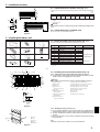
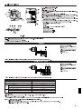
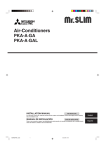
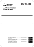
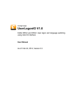
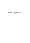
Air-Conditioners
PKA-A·GA
PKA-A·GAL
INSTALLATION MANUAL
FOR INSTALLER
For safe and correct use, read this manual and the outdoor unit installation manual thoroughly before installing
the air-conditioner unit.
MANUAL DE INSTALACIÓN
English
PARA EL INSTALADOR
Para un uso correcto y seguro, lea detalladamente este manual y el manual de instalación de la unidad exterior
antes de instalar la unidad de aire acondicionado.
Español
Contents
1.
2.
3.
4.
Safety precautions ...................................................................................
Installation location ..................................................................................
Installing the indoor unit ...........................................................................
Installing the refrigerant piping .................................................................
2
3
3
5
5.
6.
7.
8.
Drainage piping work ............................................................................... 6
Electrical work .......................................................................................... 7
Test run .................................................................................................. 12
Easy maintenance function (Option) ...................................................... 15
1. Safety precautions
s Before installing the unit, make sure you read all the “Safety precautions”.
s Please report to your supply authority or obtain their consent before
connecting this equipment to the power supply system.
Warning:
Describes precautions that must be observed to prevent danger of injury or
death to the user.
Caution:
Describes precautions that must be observed to prevent damage to the unit.
Warning:
• Ask a dealer or an authorized technician to install the unit.
• For installation work, follow the instructions in the Installation Manual and use
tools and pipe components specifically made for use with refrigerant specified
in the outdoor unit installation manual.
• The unit must be installed according to the instructions in order to minimize
the risk of damage from earthquakes, typhoons, or strong winds. An incorrectly installed unit may fall down and cause damage or injuries.
• The unit must be securely installed on a structure that can sustain its weight.
• If the air conditioner is installed in a small room, measures must be taken to
prevent the refrigerant concentration in the room from exceeding the safety
limit in the event of refrigerant leakage. Should the refrigerant leak and cause
the concentration limit to be exceeded, hazards due to lack of oxygen in the
room may result.
After installation work has been completed, explain the “Safety precautions,” use, and
maintenance of the unit to the customer according to the information in the Operation
Manual and perform the test run to ensure normal operation. Both the Installation
Manual and Operation Manual must be given to the user for keeping. These manuals
must be passed on to subsequent users.
: Indicates a part which must be grounded.
Warning:
Carefully read the labels affixed to the main unit.
• Ventilate the room if refrigerant leaks during operation. If refrigerant comes
into contact with a flame, poisonous gases will be released.
• All electric work must be performed by a qualified technician according to
local regulations and the instructions given in this manual.
• Use only specified cables for wiring.
• The terminal block cover panel of the unit must be firmly attached.
• Use only accessories authorized by Mitsubishi Electric and ask a dealer or
an authorized technician to install them.
• The user should never attempt to repair the unit or transfer it to another location.
• After installation has been completed, check for refrigerant leaks. If refrigerant leaks into the room and comes into contact with the flame of a heater or
portable cooking range, poisonous gases will be released.
1.1. Before installation (Environment)
Caution:
• Do not use the unit in an unusual environment. If the air conditioner is installed in areas exposed to steam, volatile oil (including machine oil), or sulfuric
gas, areas exposed to high salt content such as the seaside, the performance
can be significantly reduced and the internal parts can be damaged.
• Do not install the unit where combustible gases may leak, be produced, flow,
or accumulate. If combustible gas accumulates around the unit, fire or explosion may result.
• Do not keep food, plants, caged pets, artwork, or precision instruments in the
direct airflow of the indoor unit or too close to the unit as these items can be
damaged by temperature changes or dripping water.
• When the room humidity exceeds 80% or when the drainpipe is clogged, water may drip from the indoor unit. Do not install the indoor unit where such
dripping can cause damage.
• When installing the unit in a hospital or communications office, be prepared
for noise and electronic interference. Inverters, home appliances, high-frequency medical equipment, and radio communications equipment can cause
the air conditioner to malfunction or breakdown. The air conditioner may also
affect medical equipment, disturbing medical care, and communications equipment, harming the screen display quality.
1.2. Before installation or relocation
Caution:
• Be extremely careful when transporting the units. Two or more persons are
needed to handle the unit as it weighs 20 kg, 44 lbs or more. Do not grasp the
packaging bands. Wear protective gloves as you can injure your hands on
the fins or other parts.
• Be sure to safely dispose of the packaging materials. Packaging materials,
such as nails and other metal or wooden parts may cause stabs or other
injuries.
• Thermal insulation of the refrigerant pipe is necessary to prevent condensation. If the refrigerant pipe is not properly insulated, condensation will be formed.
• Place thermal insulation on the pipes to prevent condensation. If the drainpipe is installed incorrectly, water leakage and damage to the ceiling, floor,
furniture, or other possessions may result.
• Do not clean the air conditioner unit with water. Electric shock may result.
• Tighten all flare nuts to specification using a torque wrench. If tightened too
much, the flare nut can break after an extended period.
1.3. Before electric work
Caution:
• Be sure to install circuit breakers. If not installed, electric shock may result.
• For the power lines, use standard cables of sufficient capacity. Otherwise, a
short circuit, overheating, or fire may result.
• When installing the power lines, do not apply tension to the cables.
• Be sure to ground the unit. If the unit is not properly grounded, electric shock
may result.
• Use circuit breakers (ground fault interrupter, isolating switch (+B fuse), and
molded case circuit breaker) with the specified capacity. If the circuit breaker
capacity is larger than the specified capacity, breakdown or fire may result.
1.4. Before starting the test run
Caution:
• Turn on the main power switch more than 12 hours before starting operation.
Starting operation just after turning on the power switch can severely damage the internal parts.
• Before starting operation, check that all panels, guards and other protective
parts are correctly installed. Rotating, hot, or high voltage parts can cause
injuries.
2
• Do not operate the air conditioner without the air filter set in place. If the air
filter is not installed, dust may accumulate and breakdown may result.
• Do not touch any switch with wet hands. Electric shock may result.
• Do not touch the refrigerant pipes with bare hands during operation.
• After stopping operation, be sure to wait at least five minutes before turning off
the main power switch. Otherwise, water leakage or breakdown may result.
2. Installation location
2.1. Outline dimensions (Indoor unit) (Fig. 2-1)
D
Select a proper position allowing the following clearances for installation and maintenance.
(mm)
(inch)
H
Models
A12, A18
B
A
W
W
990
39
D
235
9-1/4
H
340
13-3/8
A
E
F
G
H
Min. 30 Max. 130 Min. 180 Min. 50 Min. 150
Min. 1-13/16 Max. 5
Max. 7-3/32 Min. 1-31/32 Min. 5-29/32
B Ceiling
C Wall
D Furnishing, etc
C
Warning:
Mount the indoor unit on a ceiling strong enough to withstand the weight of the
unit.
F
D
E
G
H
2.2. Outline dimensions (Outdoor unit)
Refer to the outdoor unit installation manual.
Fig. 2-1
3. Installing the indoor unit
1
3
2
3.1. Check the indoor unit accessories (Fig. 3-1)
The indoor unit should be supplied with the following accessories.
4
5
6
7
8
9
PART NUMBER
ACCESSORY
QUANTITY
LOCATION OF SETTING
1
Mount board
1
Fix at the back of the unit
2
Tapping screw 4 × 35
12
3
Pipe cover
1
4
Band
5
5
Felt tape
3
Set inside the unit
6
Wireless remote controller
1
7
Remocon holder
1
for PKA-A·GAL
8
Alkali batteries (size AAA)
2
9
Mount piece (Package)
1
0
Wired remote controller
1
for PKA-A·GA
q
Drain adaptor
1
6 - 8 are stored in a cut-out section of the packing material (styrofoam).
}
0
q
Fig. 3-1
(inch)
3.2. Installing the wall mounting fixture (Fig. 3-2)
19-1/2
12-19/32
13-19/32
10-1/4
8-1/16
3-3/4
31/32
F
5-29/32
E
2-15/16
1-1/4
25/32
0
1-3/8
5-5/16
7-15/32
9-21/32
11-13/16
14-3/16
D
15-15/16
19-1/2
A
3.2.1. Setting the wall mounting fixture and piping positions
B
0
1-3/8
2-5/32
3-5/32
G
5-1/8
7-15/32
C
9-1/16
L
M
16-23/32
6-11/16
7-15/32
0
1-9/16
5-1/2
I
16-17/32
H
9-1/16
8-9/32
10-23/32
12-7/32
12-11/16
13-3/8
K
N
B
J
s Using the wall mounting fixture, determine the unit’s installation position
and the locations of the piping holes to be drilled.
Warning:
Before drilling a hole in the wall, you must consult the building contractor.
A
B
C
D
E
F
G
W
3-15/16
H
Supporting piece
Mount board
Main body
Slot (6-11 × 20,
6P-7/16 × 25/32 inch)
Unit center
Bolt hole (14-ø14 mm,
14P-9/16 inch)
Tapping hole (49-ø5 mm,
49P-3/16 inch)
Bottom left pipe slot
(ø90 mm, 3-9/16 inch)
I
J
K
L
M
N
V
Y
Z
Bottom left pipe slot knockout hole
Bottom right pipe slot (ø90 mm, 3-9/16 inch)
Bottom right pipe slot knockout hole
Liquid pipe flare connection position
Gas pipe flare connection position
Level setting standard
Insert scale.
Hole centre
Align the scale with the line.
Y
X Z
Fig. 3-2
3.2.2. Drilling the piping hole (Fig. 3-3)
B
A
C
D
E
A
B
C
D
E
Sleeve
Hole
(Indoors)
Wall
(Outdoors)
s Use a core drill to make a hole of 90-100 mm, 3-9/16 to 4 inch diameter in the
wall in the piping direction, at the position shown in the diagram to the left.
s The hole should incline so that the outside opening is lower than the inside
opening.
s Insert a sleeve (with a 90 mm, 3-9/16 inch diameter and purchased locally)
through the hole.
Note:
The purpose of the hole’s inclination is to promote drain flow.
Fig. 3-3
3
3. Installing the indoor unit
1
3.2.3. Installing the wall mounting fixture
C
B
A
A Min. 140 mm,
5-1/2 inch
B Min. 300 mm,
11-13/16 inch
C Min. 55 mm,
2-3/16 inch
D Mount board
2
D
Fig. 3-4
s Since the indoor unit weighs near 30 kg, 66 lbs selection of the mounting
location requires thorough consideration. If the wall does not seem to be
strong enough, reinforce it with boards or beams before installation.
s The mounting fixture must be secured at both ends and at the centre, if
possible. Never fix it at a single spot or in any nonsymetrical way.
(If possible, secure the fixture at all the positions marked with a bold arrow.)
(Fig. 3-4)
Warning:
If possible, secure the fixture at all positions indicated with a bold arrow.
Caution:
• The unit body must be mounted horizontally.
• Fasten at the holes marked with ▲ as shown by the arrows.
1 Fasten a thread to the hole.
2 The level can be easily obtained by hanging a weight from the string and aligning the string
with the mark.
B
3.3. When embedding pipes into the wall (Fig. 3-5)
A
• The pipes are on the bottom left.
• When the cooling pipe, drain pipes internal/external connection lines etc are to be
embedded into the wall in advance, the extruding pipes etc, may have to be bent
and have their length modified to suit the unit.
• Use marking on the mount board as a reference when adjusting the length of the
embedded cooling pipe.
• During construction, give the length of the extruding pipes etc some leeway.
C
D
A
B
C
D
Fig. 3-5
3.4. Preparing the indoor unit
a
A
b
Fig. 3-6
Mount board
Reference marking for flare connection
Through hole
On-site piping
Rear, right and lower piping (Fig. 3-6)
1. Bind the cooling pipe and drain pipe together.
• Bind the pipes together with vinyl tape at three or more points. This will facilitate
passing the pipes through the wall.
2. Remove the corner box and knock out the knockout holes as necessary.
• Remove the corner box by pushing in a downward direction b, while at the same
time, pressing in the upper side part of the corner box a.
A Corner box
B Under cover
a
Left and left rear piping (Fig. 3-7)
1. Remove the under cover.
• Remove the under cover by sliding it towards the rear of the unit b, while at the
same time, pressing the two points marked by arrow heads a.
2. Remove the corner box and knock out the knockout holes as necessary.
A
b
B
b
a
Fig. 3-7
C
3.5. Mounting the indoor unit
1. Affix the mounting plate to the wall.
2. Hang the indoor unit on the two hooks positioned on the upper part of the mounting plate.
Rear, right and lower piping (Fig. 3-8)
3. Affix the indoor unit.
4. After connecting the pipes, put the corner box back to where it was (follow the
removal steps backwards).
A
B
A Square hole
B Hooks
B
A
B
C
A
Fig. 3-9
4
1-3/16~1-37/64
Fig. 3-8
A
(inch)
Left and left rear piping (Fig. 3-9)
3. Cut out a mounting piece from the packaging material.
4. Pull the indoor unit up towards yourself as shown in the figure below and slide the
mounting piece in to the mounting plate using the mounting piece setting marks
as reference.
5. After connecting the pipes and wiring, put the under cover back to where it was,
and remove the mounting piece and affix the indoor unit as shown in the left
figure.
6. Put the corner box back to where it was.
A Mounting piece
B Ceiling
C Rib
4. Installing the refrigerant piping
4.1. Precautions
4.1.1. For devices that use R410A refrigerant
• Use ester oil, ether oil, alkylbenzene oil (small amount) as the refrigeration oil
applied to the flared sections.
• Use C1220 copper phosphorus, for copper and copper alloy seamless pipes,
to connect the refrigerant pipes. Use refrigerant pipes with the thicknesses
specified in the table to the below. Make sure the insides of the pipes are
clean and do not contain any harmful contaminants such as sulfuric compounds, oxidants, debris, or dust.
Warning:
When installing or moving the air conditioner, use only the specified refrigerant (R410A) to charge the refrigerant lines. Do not mix it with any other refrigerant and do not allow air to remain in the lines. Air enclosed in the lines can
cause pressure peaks resulting in a rupture and other hazards.
Liquid pipe
Gas pipe
A12, A18
ø6.35mm, 1/4 inch thickness 0.8 mm, 1/32 inch
ø12.7mm, 1/2 inch thickness 0.8 mm, 1/32 inch
• Do not use pipes thinner than those specified above.
(inch)
B
45°±2°
øA
C
-6
R1
90° ±0.5°
A
2
1/3
oR
4t
D
Fig. 4-1
A Flare cutting dimensions
Copper pipe O.D.
(mm, inch)
ø6.35, 1/4”
ø9.52, 3/8”
ø12.7, 1/2”
ø15.88, 5/8”
Flare dimensions
øA dimensions (mm, inch)
8.7 - 9.1, 11/32-23/64
12.8 - 13.2, 1/2-33/64
16.2 - 16.6, 41/64-21/32
19.3 - 19.7, 49/64-25/32
4.2. Connecting pipes (Fig. 4-1)
• When commercially available copper pipes are used, wrap liquid and gas pipes
with commercially available insulation materials (heat-resistant to 100 °C, 212 °F or
more, thickness of 12 mm, 1/2 inch or more).
• The indoor parts of the drain pipe should be wrapped with polyethylene foam insulation materials (specific gravity of 0.03, thickness of 9 mm, 23/64 inch or more).
• Apply thin layer of refrigerant oil to pipe and joint seating surface before tightening
flare nut.
• Use two wrenches to tighten piping connections.
• Use refrigerant piping insulation provided to insulate indoor unit connections. Insulate carefully.
B Flare nut tightening torque
Copper pipe O.D.
(mm, inch)
ø6.35, 1/4”
ø9.52, 3/8”
ø12.7, 1/2”
ø15.88, 5/8”
Flare nut O.D.
(mm, inch)
17, 43/64
22, 7/8
26, 1-3/64
29, 1-9/64
Tightening torque
(N·m, ft·lbs)
14 - 18, 10-13
34 - 42, 25-30
49 - 61, 35-44
68 - 82, 49-59
C Apply refrigerating machine oil over the entire flare seat surface.
D Use correct flare nuts meeting the pipe size of the outdoor unit.
Available pipe size
A12, A18
ø6.35
Liquid side
–
ø12.7
Gas side
–
–
: Factory flare nut attachment to the heat-exchanger.
5
4. Installing the refrigerant piping
1
11-1/32
(inch)
E
2-1/8
22-7/8
B
D
17-11/16
6-1/32
A (Total length of flexible hose)
B Liquid pipe
C Gas pipe
B
3-3/8
C 27-9/16 A
1 Position of refrigerant and drain piping (Fig. 4-2)
• The drain pipe can be cut midway to meet the on-site conditions.
C
1-7/32
1-3/8
D
F
s Cut the knockout holes using a saw blade or an adequate knife.
Take care not to damage other parts of the unit.
C
D
2-3/8
D
2-3/4
2-3/8
1-3/8
13/32
D
7/8
13/32
E
2-3/4
5/16
2-3/4
13/16
7/8
13/32
5/16
9-21/32
(inch)
5/16
7-15/32
2-3/8
7/8
9-21/32
E
• Remove the corner box and drill a knockout hole. If a hole is made without removing the box, the drain hose could be damaged.
A Left-side piping
B Lower piping
C Right-side piping
D Remote controller cable through hole
E Corner box
13/16
B
A
D Drain hose
E Left-side piping
F Right-side piping
2 Determine the position of the knockout holes on the unit body. (Fig. 4-3)
Fig. 4-2
2
4.3. Positioning refrigerant and drain piping
E
Fig. 4-3
4.4. Refrigerant piping (Fig. 4-4)
B
D
C
E
G
A
F
Fig. 4-4
1. Remove the flare nut and cap of the indoor unit.
2. Make a flare for the liquid pipe and gas pipe and apply refrigerating machine oil
(available from your local supplier) to the flare sheet surface.
3. Quickly connect the on site cooling pipes to the unit.
4. Wrap the pipe cover 3 that is attached to the gas pipe and make sure that the
connection join is not visible.
5. Wrap the pipe cover of the unit’s liquid pipe and make sure that it covers the
insulation material of the on site liquid pipe.
6. Use the bands that are provided 4 to tighten both ends (15–20mm, 19/32 to
25/32 inch) of each pipe cover 3.
A
B
C
D
Cooling pipe and insulation (available from local supplier)
Unit’s gas pipe
E Bands 4
Unit’s liquid pipe
F On site gas pipe
Pipe cover 3
G On site liquid pipe
4.5. For twin combination
Refer to the outdoor unit unstallation manual.
5. Drainage piping work
A
B
5.1. Drainage piping work (Fig. 5-1)
• Use a PVC pipe (I.D. ø20mm, 13/16 inch) for drain piping and provide 1/100 or
more downward slope.
• Other PVC pipe sizes are available with the drain adaptor supplied.
• Make sure that there is no water leakage from the connections.
• If the drain pipe passes indoors it must be covered with insulating material (foamed
polyethylene: specific gravity: 0.03, thickness: 9 mm, 23/64 inch or more) available on the
market.
• Do not put the drain piping directly in a drainage ditch where sulphuric gas may be
generated.
• When piping has been completed, check that water flows from the end of the drain
pipe.
C
Fig. 5-1
1
2
A
a
b
C Indoor unit’s drain hose
Caution:
The drain pipe should be installed according to this Installation Manual to ensure correct drainage. Thermal insulation of the drain pipes is necessary to
prevent condensation. If the drain pipes are not properly installed and insulated, condensation may drip on the ceiling, floor or other possessions.
3
A
4
A Drain connection socket
B Field drain pipe
A
B
Preparing left and left rear piping (Fig. 5-2)
1 Remove the drain cap.
• Remove the drain cap by holding the bit that sticks out at the end of the pipe and
pulling.
A Drain cap
2 Remove the drain hose.
• Remove the drain hose by holding on to the base of the hose a (shown by arrow)
and pulling towards yourself b.
3 Insert the drain cap.
• Insert a screwdriver etc into the hole at the end of the pipe and be sure to push to
the base of the drain cap.
4 Insert the drain hose.
• Push the drain hose until it is at the base of the drain box connection outlet.
• Please make sure the drain hose hook is fastened properly over the extruding drain
box connection outlet.
B Hooks
Fig. 5-2
6
Remove the side panel of the indoor unit on the drain side. Pour water in the drain
pan and check that it comes out the drain pipe end. After confirmation, reinstall the
side panel.
PKA
Indoor unit model
1A
Maximum rating of overcurrent protective device
15A
Circuit
rating
Wiring
Wire No. × size
Minimum circuit ampacity
Indoor unit-Outdoor unit
*1
3 × AWG16 (polar)
Remote controller-Indoor unit
*2
2 × AWG22 (Non-polar)
Indoor unit earth
1 × Min. AWG16
Indoor unit-Outdoor unit S1-S2
*3
AC 208/230 V
Indoor unit-Outdoor unit S2-S3
*3
DC24 V
Remote controller-Indoor unit
*3
DC12 V
6. Electrical work
B
6.2. Remote controller
A
6.2.1. For wired remote controller
1-3/16
(inch)
1-3/16
3-9/32
1-3/16
1-37/64
D
C
A
E
F
4-23/32
C
I
G
H
Fig. 6-2
B-1.
B-2.
B
H
H
I
J
I
1) Installing procedures
(1) Select an installing position for the remote controller. (Fig. 6-2)
The temperature sensors are located on both remote controller and indoor unit.
s Procure the following parts locally:
Two piece switch box
Thin copper conduit tube
Lock nuts and bushings
A Remote controller profile
B Required clearances surrounding the remote controller
C Installation pitch
(2) Seal the service entrance for the remote controller cord with putty to prevent possible invasion of dew drops, water, cockroaches or worms. (Fig. 6-3)
A For installation in the switch box:
B For direct installation on the wall select one of the following:
• Prepare a hole through the wall to pass the remote controller cord (in order to run
the remote controller cord from the back), then seal the hole with putty.
• Run the remote controller cord through the cut-out upper case, then seal the cutout notch with putty similarly as above.
B-1. To lead the remote controller cord from the back of the controller:
B-2. To run the remote controller cord through the upper portion:
(3) For direct installation on the wall
C
D
E
F
G
H
I
J
Fig. 6-3
A
Wall
Conduit
Lock nut
Bushing
Switch box
Remote controller cord
Seal with putty
Wood screw
2) Connecting procedures (Fig. 6-4)
1 Connect the remote controller cord to the terminal block.
A To TB5 on the indoor unit
B TB6 (No polarity)
AB
Fig. 6-4
3) Two remote controllers setting
If two remote controllers are connected, set one to “Main” and the other to “Sub”. For
setting procedures, refer to “Function selection of remote controller” in the operation
manual for the indoor unit.
TB6
B
6.2.2. For wireless remote controller
1
MODEL SELECT
C
A
B
ON/OFF
TEMP
A
3
2
MODE
FAN
AUTO STOP
VANE
AUTO START
CHECK LOUVER
TEST RUN
ON STAND COOL
OFF BY
h
min
HEAT
2,4
SET
RESET
CLOCK
Fig. 6-6
D
Fig. 6-5
1) Installation area
• Area in which the remote controller is not exposed to direct sunshine.
• Area in which there is no nearby heating source.
• Area in which the remote controller is not exposed to cold (or hot) winds.
• Area in which the remote controller can be operated easily.
• Area in which the remote controller is beyond the reach of children.
2) Installation method (Fig. 6-5)
1 Attach the remote controller holder to the desired location using two tapping screws.
2 Place the lower end of the controller into the holder.
A
B
C
D
Remote controller
Wall
Display panel
Receiver
• The signal can travel up to approximately 7 meters, 23 ft (in a straight line) within 45
degrees to both right and left of the center line of the receiver.
3) Setting (Fig. 6-6)
1 Insert batteries.
2 Press the SET button with something sharp at the end.
MODEL SELECT blinks and Model No. is lighted.
3 Press the temp
button to set the Model No.
4 Press the SET button with something sharp at the end.
MODEL SELECT and Model No. are lighted for three seconds, then turned off.
Indoor
PLA, PCA, PKA (A12, A18)
PKA (A24, A30, A36)
10
8
Outdoor
heat pump models
cooling only models
heat pump models
cooling only models
A Model No.
001
033
003
035
6. Electrical work
A
MODEL SELECT
ON/OFF
4) Assigning a remote controller to each unit (Fig. 6-7)
Each unit can be operated only by the assigned remote controller.
Make sure each pair of an indoor unit PC board and a remote controller is assigned
to the same pair No.
5) Wireless remote controller pair number setting operation
1 Press the SET button with something sharp at the end.
Start this operation from the status of remote controller display turned off.
MODEL SELECT blinks and Model No. is lighted.
TEMP
3
FAN
MODE
VANE
h
TEST RUN
SET
min
RESET
2
button twice continuously.
A Pair No. of wireless remote controller
0
1
2
3–9
CLOCK
Fig. 6-7
2
min
Pair No. “0” blinks.
3 Press the temp
button to set the pair number you want to set.
4 Press the SET button with something sharp at the end.
Set pair number is lighted for three seconds then turned off.
AUTO START
CHECK LOUVER
1,4
2 Press the
AUTO STOP
Indoor PC board
Factory setting
Cut J41
Cut J42
Cut J41, J42
6.3. Function settings
3 4
6.3.1 Function setting on the unit (Selecting the unit functions)
?
1
?
2
?
3
?
4
1
TEMP.
F
MENU
E
BACK
MONITOR/SET
PAR-21MAA
G
Mode number
Setting number
Refrigerant address
Unit number
ON/OFF
ON/OFF
FILTER
DAY
CHECK TEST
OPERATION
CLOCK
C
CLEAR
A
B
D
4
1
2
1
Fig. 6-8
1
CHECK
2
CHECK
CHECK
1) For wired remote controller (Fig. 6-8)
Changing the power voltage setting
• Be sure to change the power voltage setting depending on the voltage used.
1 Go to the function setting mode.
Switch OFF the remote controller.
Press the A and B buttons simultaneously and hold them for at least 2
seconds. FUNCTION will start to flash.
2 Use the C button to set the refrigerant address (3) to 00.
3 Press D and [--] will start to flash in the unit number (4) display.
4 Use the C button to set the unit number (4) to 00.
5 Press the E MODE button to designate the refrigerant address/unit number. [--]
will flash in the mode number (1) display momentarily.
6 Press the F buttons to set the mode number (1) to 04.
7 Press the G button and the current set setting number (2) will flash.
Use the F button to switch the setting number in response to the power supply
voltage to be used.
Power supply voltage
230 V : setting number = 1
208 V : setting number = 2
8 Press the MODE button E and mode and the setting number (1) and (2) will
change to being on constantly and the contents of the setting can be confirmed.
9 Press the FILTER A and TEST RUN B buttons simultaneously for at least two
seconds. The function selection screen will disappear momentarily and the air
conditioner OFF display will appear.
2) For wireless remote controller (Fig. 6-9)
Changing the power voltage setting
• Be sure to change the power voltage setting depending on the voltage used.
1 Go to the function select mode
CHECK
ON/OFF
Press the
button F twice continuously.
(Start this operation from the status of remote controller display turned off.)
CHECK is lighted and “00” blinks.
Press the temp
button C once to set “50”. Direct the wireless remote controller
TEMP
E
C,D 3
MODE
F
FAN
AUTO STOP
VANE
AUTO START
CHECK LOUVER
TEST RUN
SET
h
min
RESET
CHECK
4
h
CHECK
button A.
toward the receiver of the indoor unit and press the
2 Setting the unit number
button C and D to set the unit number “00”. Direct the wireless
Press the temp
min
button B.
remote controller toward the receiver of the indoor unit and press the
3 Selecting a mode
C and
D buttons.
Enter 04 to change the power voltage setting using the
Direct the wireless remote controller toward the receiver of the indoor unit and press
A
B
CLOCK
the
Fig. 6-9
h
button A.
Current setting number:
1 = 1 beep (one second)
2 = 2 beeps (one second each)
3 = 3 beeps (one second each)
4 Selecting the setting number
C and
D buttons to change the power voltage setting to 01 (240 V).
Use the
Direct the wireless remote controller toward the sensor of the indoor unit and press
h
button A.
the
5 To select multiple functions continuously
Repeat steps 3 and 4 to change multiple function settings continuously.
6 Complete function selection
Direct the wireless remote controller toward the sensor of the indoor unit and press
the
button E.
Note:
Whenever changes are made to the function settings after installation or maintenance, be sure to record the changes with a mark in the “Setting” column of
the Function table.
6.3.2 Function setting on the remote controller
Refer to the indoor unit operation manual.
11
9
10
7. Test run
7.2.3. Using SW4 in outdoor unit
Refer to the outdoor unit installation manual.
B
E D
A
B
7.3. Self-check
7.3.1. Wired remote controller (Fig. 7-3)
1
2
3
4
CHECK
ERROR CODE
TEMP.
C
MENU
MONITOR/SET
BACK
PAR-21MAA
ON/OFF
ON/OFF
DAY
CLOCK
ON/OFF
A
B
C
D
CHECK button
Refrigerant address
TEMP. button
IC: Indoor unit
OC: Outdoor unit
E Check code
F Unit address
TEMP
4
FILTER
CHECK TEST
OPERATION
CLEAR
MODE
A
FAN
AUTO STOP
VANE
AUTO START
CHECK LOUVER
2
TEST RUN
h
3
min
Turn on the power.
Press the [CHECK] button twice.
Set refrigerant address with [TEMP] button if system control is used.
Press the [ON/OFF] button to stop the self-check.
7.3.2. Wireless remote controller (Fig. 7-4)
SET
ERROR CODE
RESET
CLOCK
1 Turn on the power.
CHECK
B
button twice.
2 Press the
(Start this operation from the status of remote controller display turned off.)
E
ERROR CODE
A CHECK begins to light.
B “00” begins to blink.
Fig. 7-4
h
3 While pointing the remote controller toward the unit’s receiver, press the
button. The check code will be indicated by the number of times that the buzzer
sounds from the receiver section and the number of blinks of the operation lamp.
4 Press the ON/OFF button to stop the self-check.
F
Fig. 7-3
• Refer to the following tables for details on the check codes. (Wireless remote controller)
[Output pattern A]
Beeper sounds
OPERATION
INDICATOR
lamp flash
pattern
Beep
Beep
Beep
Beep
Beep
Beep
1st
2nd
3rd
nth
1st
Beep
2nd · · · Repeated
Off
On
On
Off
On
On
On
On
0.5 sec. Approx. 2.5 sec. 0.5 sec. 0.5 sec.
Self-check Approx. 2.5 sec. 0.5 sec. 0.5 sec. 0.5 sec.
starts
(Start signal
Number of flashes/beeps in pattern indicates the check
Number of flashes/beeps in pattern indicates
received)
code in the following table (i.e., n=5 for “P5”)
the check code in the following table
[Output pattern B]
Beeper sounds
OPERATION
INDICATOR
lamp flash
pattern
Beep
Beep
1
Off
Self-check Approx. 2.5 sec.
starts
(Start signal
received)
[Output pattern A]
On
Approx. 3 sec.
st
Beep
2
nd
Beep
3
rd
On
On
On
0.5 sec. 0.5 sec. 0.5 sec.
Beep
n
Beep
th
On
0.5 sec.
1
Off
Approx. 2.5 sec.
Number of flashes/beeps in pattern indicates the check
code in the following table (i.e., n=5 for “U2”)
On
Approx. 3 sec.
st
On
0.5 sec.
Beep
2nd · · · Repeated
On
0.5 sec.
Number of flashes/beeps in pattern indicates
the check code in the following table
Errors detected by indoor unit
Wireless remote controller
Beeper sounds/OPERATION
INDICATOR lamp flashes
(Number of times)
1
2
3
4
5
6
7
8
9
10
11
12
No sound
Wired remote
controller
Symptom
Remark
Check code
P1
P2, P9
E6, E7
P4
P5
P6
EE
P8
E4
–
–
Fb
––––
Intake sensor error
Pipe (Liquid or 2-phase pipe) sensor error
Indoor/outdoor unit communication error
Drain sensor error
Drain pump error
Freezing/Overheating safeguard operation
Communication error between indoor and outdoor units
Pipe temperature error
Remote controller signal receiving error
–
–
Indoor unit control system error (memory error, etc.)
No corresponding
13
11
7. Test run
[Output pattern B] Errors detected by unit other than indoor unit (outdoor unit, etc.)
Wireless remote controller
Wired remote
controller
Beeper sounds/OPERATION
INDICATOR lamp flashes
(Number of times)
1
2
3
4
5
6
7
8
9
10
11
Symptom
E9
UP
U3, U4
UF
U2
U1, Ud
U5
U8
U6
U7
U9, UH
12
13
14
–
–
Others
Remark
Check code
Indoor/outdoor unit communication error (Transmitting error) (Outdoor unit)
Compressor overcurrent interruption
Open/short of outdoor unit thermistors
Compressor overcurrent interruption (When compressor locked)
Abnormal high discharging temperature/49C worked/insufficient refrigerant
Abnormal high pressure (63H worked)/Overheating safeguard operation
Abnormal temperature of heat sink
Outdoor unit fan safeguard stop
Compressor overcurrent interruption/Abnormal of power module
Abnormality of super heat due to low discharge temperature
Abnormality such as overvoltage or voltage shortage and abnormal synchronous
signal to main circuit/Current sensor error
–
–
Other errors (Refer to the technical manual for the outdoor unit.)
For details, check the LED display
of the outdoor controller board.
*1 If the beeper does not sound again after the initial two beeps to confirm the self-check start signal was received and the OPERATION INDICATOR lamp does not come on,
there are no error records.
*2 If the beeper sounds three times continuously “beep, beep, beep (0.4 + 0.4 + 0.4 sec.)” after the initial two beeps to confirm the self-check start signal was received, the
specified refrigerant address is incorrect.
• On wireless remote controller
The continuous buzzer sounds from receiving section of indoor unit.
Blink of operation lamp
• On wired remote controller
Check code displayed in the LCD.
• If the unit cannot be operated properly after the above test run has been performed, refer to the following table to remove the cause.
Symptom
Wired remote controller
PLEASE WAIT
PLEASE WAIT → Error code
For about 2
minutes following
power-on
After about 2
minutes has
expired following
Display messages do not appear even power-on
when operation switch is turned ON
(operation lamp does not light up).
Cause
LED 1, 2 (PCB in outdoor unit)
After LED 1, 2 are lighted, LED 2 is turned off,
then only LED 1 is lighted. (Correct operation)
• For about 2 minutes following power-on, operation of the
remote controller is not possible due to system start-up. (Correct operation)
Only LED 1 is lighted. → LED 1, 2 blink.
• Connector for the outdoor unit’s protection device is not connected.
• Reverse or open phase wiring for the outdoor unit’s power
terminal block (L1, L2, GR)
Only LED 1 is lighted. → LED 1 blinks twice,
LED 2 blinks once.
• Incorrect wiring between indoor and outdoor units (incorrect
polarity of S1, S2, S3)
• Remote controller wire short
On the wireless remote controller with condition above, following phenomena takes place.
• No signals from the remote controller are accepted.
• OPE lamp is blinking.
• The buzzer makes a short pipng sound.
Note:
Operation is not possible for about 30 seconds after cancellation of function selection. (Correct operation)
For description of each LED (LED 1, 2, 3) provided on the indoor controller, refer to the following table.
LED 1 (power for microcomputer)
Indicates whether control power is supplied. Make sure that this LED is always lit.
LED 2 (power for remote controller)
Indicates whether power is supplied to the remote controller. This LED lights only in the case of the
indoor unit which is connected to the outdoor unit refrigerant address “0”.
LED 3 (communication between indoor and outdoor units only A-control) Indicates state of communication between the indoor and outdoor units. Make sure that this LED is
always blinking.
14
12
8. Easy maintenance function [This function only for A-control]
Display example (Comp discharge temperature 147°F)
C
A
By using the maintenance mode, you can display many types of maintenance data
on the remote controller such as the heat exchanger temperature and compressor
current consumption for the indoor and outdoor units.
This function can be used whether the air conditioner is operating or not.
During air conditioner operation, data can be checked during either normal operation
or maintenance mode stable operation.
* This function cannot be used during the test run.
* The availability of this function depends on the connecting outdoor unit. Refer to the
brochures.
B
D
Maintenance mode operation procedures
(1) Press the TEST button for three seconds to
activate the maintenance mode.
(2) Press the TEMP.
Display A MAINTENANCE
buttons to set the refrigerant address.
Display B
(3) Select the data you want to display.
Cumulative
operation time
Compressor
information
MENU
Outdoor unit
information
Display A
Heat exchanger
temperature
Display A
ON/OFF
Indoor unit
information
COMP ON
x10 HOURS
OUTDOOR UNIT
H·EXC. TEMP
Indoor room
temperature
Display A
INDOOR UNIT
INLET TEMP
Operation
current
ON/OFF
number
COMP ON
x100 TIMES
COMP ON
CURRENT (A)
Outdoor ambient
temperature
Comp discharge
temperature
OUTDOOR UNIT
OUTLET TEMP
OUTDOOR UNIT
OUTDOOR TEMP
Filter operation
time
Heat exchanger
temperature
INDOOR UNIT
H·EXC. TEMP
INDOOR UNIT
FILTER USE H
* The filter operation time displayed is the number of hours the filter has been
used since the filter reset was performed.
Stable operation
Using the maintenance mode, the operation frequency can be fixed and the operation can be stabilized. If the air conditioner is stopped, use the following procedure to start this operation.
Press the MODE button to select the operation mode.
Stable cooling
operation
(4) Press the FILTER button.
Display A
(5) The data is displayed in C.
COOL
STABLE MODE
Stable heating
operation
HEAT
STABLE MODE
Stable operation
cancellation
STABLE MODE
CANCEL
(Airflow temperature display example)
Flashing
Press the FILTER button.
Display C
Waiting for
response
Approx.
10 sec.
147°F
* Repeat steps (2) to (5) to check another date.
Display D
(6) Press the TEST button for three seconds or press the
deactivate the maintenance mode.
Stable
operation
Waiting for stable
operation
ON/OFF button to
10-20 min.
* You can check the data using steps (3) to (5) of the maintenance mode operation procedures while waiting for the stable operation.
15
13
This product is designed and intended for use in the residential,
commercial and light-industrial environment.
Please be sure to put the contact address/telephone number on
this manual before handing it to the customer.
HEAD OFFICE: TOKYO BLDG., 2-7-3, MARUNOUCHI, CHIYODA-KU, TOKYO 100-8310, JAPAN
BG79U874H02-A
BG79U874H02
Printed in Japan