1
IMPORTANT MANUAL
Do Not Throw Awa_
i
i i
iHi .ll...,.
Operator's
Manual
MODEL NO.
358.797121-26cc
(16" Cutting
Par
Always Wear Eye Protection During Operation
26€€ GAS WEEDWACKER _
A WARNING:
Read the Operator'sManual
md Follow All Warnings
and Safety Instructions.
_ure
ToDo So Can Result
in Serious I_iury.
Sold
....................
530-067909-4-07112/91
by Sears,
Roebuck
2 Cycle Engine
Fuel Mix 40:1
®Assembly
o Operation
o Maintenance
and
Coo, Chicago,
• Repair Parts
Iti. 60684
U.S.A.
N,
©Sears,
Roebuck
and Co,
1991
ONE
YEAR
LIMITED
WARRANIY
ON CRAlrl'SMAN
WEEKWACKER
®
For One Year from dale of archase when this Weedwacke¢ _ is maintained
lubricated and tuned up according to the operating
and maintenance instructionPs in the operators manual Sears will repair free of charge any defect in rnateria] or workmanship
This wammly
excludes nylon line spark plug and a r c eaner" wb ch are expendable
paris and become worn during nomlal use
._
WARRANTY SERVICE IS AVAILABLE BY CONIACTING
IHE NEARESI" SEARS SERVICE CENIER/DEPARIMENI
IN THE UNIFED STALES 7his warranty applies only while this product is in ase in the United States
'This '_trvant)'
gives you specific
SEARS,
legal rights
ROEBUCK
and you may also have other rights which vary from state to stale
AND CO, DEPT
TABLE
D/731CR-W, SEARS
rOWER
CHICAGO,
_.
IL 60684
.,_
OF CONTENTS
3
6
WARNINGS AND SAFETY INSTRUCTIONS
KNOW YOUR TRIMMER
ASSEMBLY ..
ACCESSORIF_
.....
ENGINE INFORMATION
A Fueling Your Engine
B. Pre-Operation Checks
C Starting Instructions
D Operating Instructions
USING YOUR TRIMMER
A Irimmer Safety
B Trimmer Line Advance
C Cutting Methods
D Line Replacement
GENERAL MAINTENANCE ................
A Maintenance Safety ....................
7
17
17
B_ Air Filter....................
17
I0
C. StarterRope ............................
18
11
11
12
12
D
E
F.
G,
19
20
22
22
13
REPAIR
13
INDEX
14
14
15
16
QUICK REFERENCE PAGE ..................... 27
Flexible Drive Shaft Lubrication ..............
Carburetor Adjustments ................
Storage .............................
Trouble Shooting Chart .......................
PAR'IS
LIST
.........................
........................................
23
26
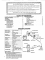
SPEC F| ATION
"ENGINE'
'TTPE:
i DISP,LACEMENT!
ENGINE
2-Cycte, Air-Cooled
...........
R_M:
IGNITION SWITCH
26cc
Operating ' 7500
Idle -- 2800 - 3200
I NmON:................SoiidS te
CARBURETOR:
ENGINE "OFF":
Diaphragm All Positions with
adjustable fue! mixture jets
Positive Switch
STARTER:
Auto Rewind
MUFFLER:
2bmpemture
Limiting
(not
spark arresting; see note p,5)
CLUTCH:
FUEL TANK:
17 tL 0Z,
'.................
SPARK pLUG:
71-85854 <€i_i4)
SPARK,,PLUG GAP:
MODULE AIR GAP:
.025"
SHIELD
.010" / .0t4"
LUBRICATION:
CUTIING
LINE:
"SHAFT LEN_:
(See "Fueling Your'Engine")
DS0" Diameter Sears Laser
Line ®
"_'_MUFFLI_
48"
B_--"e
NOTE: LASER LINE ® tS A REGISTERED TRADEMARK
OF
WHITE CONSOLIDATED INDUSTRIES, INC
M'ANUFACI_UREDUNDER ONE OR MORE OF tHE FOLLOWINGU.S
PATENTS:3 708,967;3 826 068;3_859,776;4_035,912;4,052_789:4,054,992;
4_067,108:4, t04,797; 4.114=269;4_1245)38;4,156_31214,156,967;4_161,820;
4,167,8|2; 4_269;372;4,286,675; 4_107,901;4. t t2,653; 4_136o446;4,168,572;
4,183,138;4,189.833; 4,21 t ,004;4°211_005;4.236,311:4_236_312;4,290,200;
4.362,ff/4;4_366,622;4_382,356;4,451,983; 4,483,069; 4.798,185;4,819.742;
4,823,465; 4,825_548; 4,835,867; 4,841.929; 4.846,123; 4852.258;
DES 249.630 U S AND FOREIGNPATENIS PENDING
_"_
SPARK PLUG
I'RIMbtF_
HE.M)
This tool can cause serious injury or blindness to the operator and others. The warnings and safety instructions in this manual
must be followed to provide reasonable safety and efficiency in using this tool, The operator is responsible for following the
warnings and instructions in this manual and on the tool Read the entire Operator's Manual before assembling and using
this tool! Restrict the use of this power tool to persons who read, understand, and follow the warnings and instructions
in this manual and on the tool.
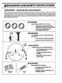
A D GEK
NEVER USE BLADES
WITH THIS TOOL.
-- THE BLADE CAN COME OFF AND
SERIOUSLY INJURE YOU AND OTHERS.
-- THIS TOOL IS DESIGNED FOR
LINE TRIMMER USE ONLY.
AW&I IG
THE TRIMMER LINE CAN THROW OBJECTS
VIOLENTLY
YOU CAN BE BLINDED OR INJURED.
-- WEAR EYE AND LEG PROTECTION.
HAZARD ZONE FOR THROWN OBJECTS.
-- THE TRIMMER LINE CAN THROW
OBJECTS VIOLENTLY°
-- OTHERS CAN BE BLINDED
INJURED.
OR
-- KEEP PEOPLE AND ANIMALS
3O FEET AWAY.
READ OPERATOR'S
--
MANUAL.
FOLLOW ALL WARNINGS
INSTRUCTIONS.
OPERATOR'S
MANUAL
AND
........................
i,i
WARNINGS AND SALTY
IIgSTN,
i
i,i
A OPERATOR SAFETY
1. Inspectentiretoolbeforeeachuse. Replacedamagedparts.
Check for fuel leaks and make sure all fasteners are in place
and securely fastened
2 Replace trimmer head parts that a_e cracked, chipped,
broken, or damaged in any other way before using the tool_
3 Use only 080" diameter Sears Laser Line Never use
wi_e. rope. string, etc
4 Be sure the shield is properly attached.
5. Use only the specified trimmer head See "Specifications."
Make sure the trimmer head is properly installed and
fastened. Refer to "Assembly"
6 Be sure the trimmer head stops turning when engine idtes_
See "Carburetor Adjustments."
7. Make carburetor adjustrnents with the drive shaft housing
supported to prevent the trimmer line from contacting any
object Hold the tool by hand; do not use the optional
shoulder strap for support
8 Keep others away when making carburetor adjustments..
9. Use only accessories or attachments as recommended for
this tool by Sears
A FUEL SAt Ir"I "
1_ Move at least 10 (Let away from fueling site betbre start_
ing engine.
2. Use a container approved for fuel..
3 Do not smoke or allow smoking near fuel or the tool or
while using the tool
4. Wipe up all fuel spills before starting engine.
5 Stop engine before removing fuel cap, Allow the engine
to cool before refueling.
6. Run fuet out of the rue! system before storing the tool
2 Store tool and fuel in an area where fuel vapors cannot reach
sparks or open flames from water heaters, electric motors
or switches, furnaces, etc
,111ii1,1
,,i,iiiii1,1,,,,,,,i
CD' t'/NG
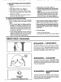
1 Always wear a safety face shield or safety goggles. See
"Accessories"
2 Keep hair, fingeIs, and all othet parts of the body away
h'om openings and moving parts Always wear heavy,
long pants,, boots, and gloves Do not go barefbot or wear
sandals, jewelry, short pants, loose clothing, or clothing with loosely hanging straps, ties. tassels, etc, Secure
hair so it is above shoulder length Being fully covered
will help protect you from pieces of toxic p)ants (such
as poison ivy) thrown by the Trinmaer Head, which
could be more of a hazard than touching the plant itself
3. Do not operate this tool when you are tired, ill, or under the
influence of alcohol, drugs, or medication.
4. Always use the assist handle. See "Assembly,"
5. Wear hearing protection if you use this tool for more than
! V2hours per day.
6. Never start or run the engine inside a closed room or building Breathing exhaust fumes can kilt
7. Keep handles fi'ee of oil and fuel.
& TOOL SAFETY
..... i
, ,
i
........
r
r
1. Inspect the area to be cut before each use Remove objects
(rocks, broken glass, nails, wire, string, etc ) which can be
thrown or become entangled in the trimmer head_
2. Keep others including children, animals, bystanders, and
helper's outside the 60 tbot Hazard Zone Stop the engine
immediately i[ you are approached.
3. Always keep the engine on the right side of your body,
4 Hold the tool firmly with both hands
5. Do not overreach or use from unstable surfaces such as
ladders, trees, steep slopes, rooftops, etc, Use extra care
when cleaning on stairways Keep firnafooting and b',dance
at all times
6 Keep trimmer head below waist level
7 Do not raise the engine aboveyour waist The trirrmaer head
can come dangerously elose to your body.
8 Keep alt parts ofyour body awayfrom the trimmer head and
muffler when the engine is running
9 Useonly forjobs explained in this manual.
A MAINTENANCESAFETY
1_ Maintain the toot according to reco_ranended procedures.
Keep the trimmer line at the proper length.
2 Never start the engine with the clutch shroud removed The
clutch can fly apart and cause serious injury
3 Disconnect the spark plug before performing maintenance
except for carburetor adjustments.
4. Make carburetor adjustments with the drive shaft housing
suppoaed to prevent the trimmer line from contacting any
object.. Hold the toot by hand; do not use the optional
shoulder strap for support
5 Keep others away when making carburetor adjustments
6. Use only genuine replacement parts as recommended
by Sears_
•
T L4 .SPORTL G/ D
STOOGE
l Hand carry the tool with theengine stopped and the muffler
away from your body
2o Allow the engine to cool, run fuel out ofthe fuel system, and
secure the toot before transporting in a vehicle or storing
3. Before storing the tool, use up fuel left in the fuel lines and
carburetor by starting the engine and letting it run until it
stops.
4. Store tool and fuel in an area where fuel vapors cannot reach
sparks or open flames from water heaters, electric motors
or switches, furnaces, etc.
5_ Store the tool so the line limiter cannot accidenta!ly cause
injury. The tool can be hung by the drive shaft housing or
by the bracket below the engine
6. Store tool out of reach ofchildren,
If situations occur which are not covered in this manual, use
care and good judgement. Contact your Sears Service
Center/Depa_nent if you need assistance.
SAFETY NOTICE
Exposure to vibrations through prolonged use of gasoline powered hand tools could cause blood vessel or nerve damage in the fingers,
hands, and wrists ofpeople prone to circulation disorders or abnormal swellings. Prolonged use in cold weather has been linked
to blood vessel damage in otherwise healthy people. If symptoms occur such as numbness, pain, loss of strength, change in skin
color or texture, or loss of feeling in the fingers, hands, or wrists, discontinue the use of this tool and seek medical attention. An
anti-vibrati on system does not guarantee the avoidance of these problems. Use rs wh o operate power tools on a continual and regular basis must monitor closely their physical condition and the condition of this tool.
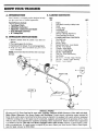
KNOW YOUR TRIMMER
._1,11
.................
C. _RTON
A. _ODU_'ION
Your Tr'immer is a versatile product designed
you give your lawn a finished appearance.
to help
Special Features Include:
•
•
e
•
o
Centrifugal
Clutch
All-Position Carburetor
Adjustable, Cushioned Assist Handle
Semi-Automatic
Line Feed
16"Cutting Path
K UNP&_G
L Remove contents
done so.
KEY
NO.
1
2
3
4
5
6
---
_ISTRU_ON$
from the canon
if you have not
2. Check parts against the list below
3. Examfinepartsfordamage
Donotusedamagedpans
4 Notifi/),our Sears Store immediately ija part is miss'ing cn damaged
NOTE: it is normal to hear the fuel fdter rattle in an empty
fue! tank
!3
14
16
CONTENTS
7
8
9
10
i1
12
13
t4
15
16
17
18
19
QTY_
Engine
Drive Shaft Assembly w/Safety Label
Shield
Trimmer Head
Assist Handle
2-cycle Engine Oil
Operator's Manual (Not Shown)
Loose Parts Bag (Not Shown)
* LOOSE PARTS BAG CONTENTS:
Flex Shaft Lube
Screw - Shield
Bracket - Shield
Squared Head Screw - Assist Handle
Hex Nut - Assist Handle
T-Handle - Assist Handle
Hex Screw - Clutch Shroud
Hex Nut - Clutch Shroud
Dust Cup - Drive Shaft Housing
Hex Wrench
Hex Screw - Thfottle Trigge_ Housing
Hex Nut - Throttle Trigger Housing
Bracket - Assist Handle
I
2
1
1
I
1
2
2
!
1
I
I
I
SAFETY LABEL
7
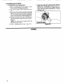
SPECIAL
NOTICE
For users on U.S. Forest Land and in some states, including Cahfornia (Public Resources Codes 4442 and 4443),
Idaho, Maine, Minnesota,
New Jersey, Oregon, and Washington: Certain internal combustion engines operated on
forest, brush, and/or grass-covered land in the above areas are required to be equipped with a spark arrestor, maintained
in effective working order, or the engine must be constructed, equipped, and maintained for the prevention of fire_ Check
with your state or local authorities for regulations pertaining to these requirements, Failure to follow these requirements
is a violation of the law. This unit is not factory-equipped
with a spark arrestor;
however, a spark arrestor is available as an optional part If a spark arrestor is required in your area, contact your Seres Service Center or Parts Department for Spark Arrestor kit #952-701612_
...........................................
,,,,,i?,?
_I;,L'_I_,:_??+_;,
i?,+i
';L,,,;,i,:;,'',,+........
,+
___P'
(_'too|
r.......................................................
is rece|vedas_embJed,
repeat all steps in thissecthm
to be sure assembly
is_
and is m_ijusted for the operator.)
This Operator's Manual has been developed to help you
assemble the tool and to provide its safe operation, It is
important thai you read the entire manual to become
familiar with the tool below you begin assembly
a+ Flathead
Screwdriver+
b. 1-1/4 inch wrench or adjustable wrench+
c, Hex Wrench provided with tool+
.............
3,','
.......
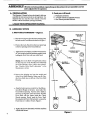
B, AS._EMBLY
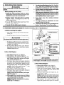
1. D[_IVE $_
S_PS
HOUSING -- Figure
1
DRIVE SHAFI
HOUSING
a o Place the two Screws (from the loose parts bag) into
the holes on the Clutch Shroud as shown in Figure I
b, Position the Lock-Nuts (from the loose parts bag)
in the hex openings in the Clutch Shroud,
' RIDGE
CLUTCH
SHROUD
c, Tighten theScrewswith the smatl hexwrench provid ed just enough to hold the hardware together while
holding the Lock-Nuts with your other hand,,
NOTE: Dirt on the Shaft will significantly reduce
the life of the tool, Ifrthe Flexible Drive Shaft falls
out of the Housing, clean, telube, then reinstall,
See "Flexible Drive Shaft Lubrication"
in the
Maintenance section
d Remove the shipping cap fl'om the straight end
of the Drive Shaft Housing, Make sure the Flexible Drive Shaft does not fall out of the Drive Shaft
Housing,
e
Align the bottom groove on the Drive Shaft Housingwiththe Ridge on theinner, lowerwallof the
Clutch Shroud opening, Turn the Arbor Shaft as
necessary to align the square end of the Flexible
Drive Shaft with the square inside the Clutch
Shroud opening+ Firmly push the Drive Shaft
Housing into the Clutch Shroud until it contacts the
Foam Grip or is within I/8 inch+ Figure 1.
f. Tighten the Screws alternately
wrench until secure.
with the small hex
+
I
I
I
I
t
®
GROOVE
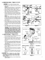
I_WI'ION:J
Do not kink the throttle
cable.
ao Slide the Throttle Trigger Housing away flora the
Foam Grip
NOTE: Betbre performing step "b', push the barrel
end of the throttle cable into the sheath until the
barrel contacts the sheath, Figure 2 (inset)
b, Insert the Throttle Cable through the tunnel in the
Foam Grip until the end of the Cable extends at
least 2 inches beyond the Grip, Figure 2,
c Hold the Trigger away flora the Drive Shaft Housing and insert the barrel end of the Throttle Cable
into the round opening in the Trigger as shown in
Figure 2,
NOTE:
When inserting the barrel end of the
Throttle Cable into the round opening in the Trigger, make sure that the barrel is completely inserted
and the Throttle Cable is located in the split in the
Aim, Figure 4,
d, Push the Triter back into the Housing while guiding the Cable through the split in the arm (Figure
3,) Guide the arm into the Foam Grip tunnel while
replacing the Throttle Trigger Housing flush against
the Grip
e Hold Trigger against the Foam Grip while inserting the Screw and Nut Figure 5 See Caution below
ICAUTION:] Do not overtighten the screw. Make
sure the trigger will move freely. There must be at
least 1/8" free play in the trigger. Figure 5. Make
sure the trigger will move freely so the engine can
fully return to idle when the trigger is released. The
trimmer head must not turn at idle speed to avoid
serious injury to the operator and others.
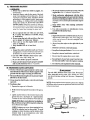
3. ASSIST
HAN]r)LE
,-- Figures
ROUND HOLE
IN
TRIGGER
Z
Assist
/
Throttle
Trigger
Housing
_
Square
Nut
%
6 & 7
a, Insert the end of the Drive Shaft Housing through
the Assist Handle, Figure 6 (inset)
b, Align the Assist handle between the SatEty Label
and the Throttle Trigger Housing Seat the Drive
Shaft Housing in the groove in the Assist Handle
Figure 6,
c, Insert the tab on the Assist Handle Bracket into the
slot on the Assist Handle, Figure 6o Then, lay the
Assist Handle Bracket into position over the Drive
Shaft Housing.
do Drop the threaded end of the square-head T-Handle
Screw through the opening in the top of the THandle Figure 7,
e Pull on the threaded end of the Screw to bring the
square head of the Screw past the pin inside the
T-handle
Figure 7,
f Insert the Screw up through the hole in the Assist
Handle and then through the Assist Handle Bracket,
Figure 6,
['-C'-AUTION:'_ When
adjusting
the Assist Handle
for comfort, be sure that the Assist Handle remains
between Engine and Safety Label on Drive Shaft
Housing. Figure 6.
h Adjust Assist Handle up or down the Shaft Housing for comfort.
T-Handle
_Assist
Handle
Screw
Groove
Figure
Before
Assembly
6
Top View
Assembled
Square Head
Screw Seated
Sere_
T Handle
Figure
7
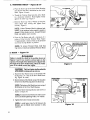
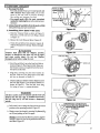
4° _R
HEAD
_
F_ures
8 _ 9
a_ Place the Dust Cup on the Drive Shaft Housing
over the hex nut that is assembled on the Arbor
Shaft. Figure 8 (inset)
b Thread the Trimmer Head onto the Arbor Shaft
in a clockwise direction
Hand tighten firmly
against the Dust Cup
Figure 7
DRIVE
SHAVF f
ARBOR
SHAFT
Hold the Dust Cup with a Wrench to keep the
Arbor' Shaft from turning and tighten head
securely Figure 8
NOTE: Unless Trimmer' Head is tightened adequately, it can unthread when engine is started or
stopped If this situation occms, reinstall Trimmer
Head and tighten more securely
Figure
8
d Press the Pap Button and pull a mininmm of 4
inches of Line from the Trimmer Head+ Figure
9_ Approximately 2 inches of line can be advanced
each time the Tap Button is pressed
NOTE______S+:
To remove Trimmer Head, hold Dust
Cup with a wrench and unthread Trimmer Head.
5. $Meld
,-, Fllgure
Approxim_y
10
_TAP
.Aw_G
Failure to install the shield in the position shown in
Figures 8 and I1 can result in serious injury to the
operator. The length of the shield must be aligned with
the length of the drive shaft housing. Direct the widest
part of the shield toward the engine.
Figure
2 inches of line
BtYlTON
9
[CA_ON:
l The Line Limiter (on the underside
of the shield) is sharp and can cut you.
a Match the Key (Raised area) on the Shield with
the Keyway ("V" slot) on the Drive Shaft Housing Figure 10 (inset)
b Rest the bottom of the Shield on top of the shoulder
of the Drive Shaft Housing above the Dust Cup,
WIDEST PART
OF SHIELD
HARDWARE SHOWN :
ACTUAL SIZE
NOTE: The bottom of the Shield must rest on top of
the shoulder' of' the Drive Shaft Housing
Install the Shield retaining Bracket and Screws as
shown in Figure 10
NOI'E: It is easier to start the Screws with a screwdriver and finish tightening with a 3/8" wrench
d,
sun"
scow
SHOt LDER .....
I)US'T ('I'P.
KEYWA¥_
+" "
1t
Tighten the Screws evenly and securely.
NOTE: A small space may be left between the
Bracket and the Shield when hardware is fully
tightened
Figure
10
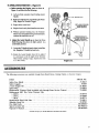
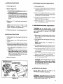
6. OPI_tA'nNG
_ON
-- 1_,-_
11
e. Before starting the Engine, stand as shown in
Figure ll and check for the following:
I).. Left arm fully extended,
Handle.
hand holding Assist
RIGHI ARM
SLIGHTLY BENT,
HAND HOLDING
FOAM GRIP,
.,*----" EYE PRO'IE(TFION
FINGERS ON
2). Right arm slightly bent, hand holding the Foam
Grip, fingers on Throttle Trigger.
TRIGGEI!
-.\
3). Engine below waist level.
THROTTLE
4), Weight of tool evenly distributed between arms.
LEFT ARM EXTENDED
•HAND HOLDING
ASSIST HANDLE
_
5) Without operator bending over, the Trimmer
Head is nearand parallel tothe ground and easily
contacts the material to be cut.
b. Adjust the Assist Handle up or down the Drive
Shaft Housing (but above the Safety Label) to a
comfortable position
IRIMblER
HEAD IS
NEAR THE GROUND AND
EASILY CONTACIS
MATERIAL TO BE CUI
F.2-_GINE
IS BELOW
WAIST LEVEl.
!). Loosen the T-Handle by hand, adjust Assist Handle. Retighten T-Handle by hand only.
2). Rotate the Assist Handle flora left to right if'
it is necessary to tilt the angle of the Trimmer
Head (when cutting a large, sloped area such
as a ditch bank).
The following accessories
are available through
Sears Retail Stores,
Catalog
Outlets,
or Service
ITEM
Centers
STOCK
Safety Face Shield .................................................................
Safety Goggles .....................................................................
2-Cycle Engine Oil ................................................................
Spark Plug ......................................................................
Replacement
Trimmer
Head (available only through
Replacement
.080" Dia, Nylon Trimmer
Line
-- 400 ft ......................................................................
-- 200 ft ......................................................................
-- 100 ft ......................................................................
Sears
Service
Centers)
..............
NO.
9-18613
9-1859
71-30143
71-85854
71-85800
71-85778
71-85608
71-85771
Replacement
Spool with Line ......................................................
Shoulder Strap Kit ................................................................
Flex Shaft Lube ...............................................................
71-85811
71-85783
530-030102*
Spark Arrestor
Kit .............................................................
Operator's
Manual ..............................................................
952-701612*
530-067909*
*Avnilable through yore SEARS SERVICE
CENTERiCATAt,OGUE.
l, m HiINHmiHmNil
A. _ELING
1. $_E_.
YOUR
3. USE THE
ENGINE
S&FETY
a Use only recommended
fuel mixtures.
b_ Mix and pour fuel outdoors and where there are
no sparks or flames
c Use a container approved for fuel,
d, Do not smokeor allow smoking near fuel or the tool
of' while using the tool
e. Wipe up all fuel spills before starting the engineo
ILgG_
UNLEADED
+
old. After a short period of time, gasoline will chemically break down and form compounds that cause
hard starting and damage in 2-cycle engines.
® The correct measure of gasoline to oil is very
important. Too much oil in the mixture will foul the
spark plug
[CAu'IrlIoN:] Too little oil or incorrect
cause the engine to overheat and seize.
10
oil will
"---
I1:SEARS 2-cycle air cooled engine oil is not available, use a good quality, 2-cycle air cooled engine
oil mixed at a ratio of 16:1 (8 oz oil to ! gallon
gasoline)
4. DO N_
USE:
o NMMA Oil-- National Marine Manufacturers
Association ((brmerly BIA)
-- Does not have proper additives tbr 2-cycte, aircooled engines and can cause engine damage,
• AUTOMOTIVE
OIL --- Does not have proper additives for 2-cycle, air_
cooled engines and can cause engine damage,
M_TURE
o Gasoline must be clean and not over two months
40:1 Ilalh_
I-:M;INE Oil O,2,,t
SEARS 2-cycte air cooled engine oil mixed at 40:1
is strongly recommended
h Before storing tool, use up fuel left in carbinetot and fuel lines by starting engine and letting
it run until it stops.
io Store tool and fuel in an area where fuel vapor_
cannot reach sparks or open flames from water
heaters, electric motors or switches, furnaces, etc
® Genuine Sears 2-cycle engine oil mixed at 40:1 is
strongly recommended for the protection of your
unit. Extensive engineering tests have proven that
Sears 2-cycte engine oil resists break-down at
operating temperatures common to 2-cycle engines,
resulting in dependable performance
and longer
engine life_
¢
GASOLINE
Move at least 10 feet away from fueling site
before starting engine,
g Stop engine before removing fuel cap. Allow the
engine to cool before refueling.
Your tool is powered by a 2-cycle engine which
requires a fuel mixture of regular unleaded gasoline and a high quality engine oil specially made
for 2-cycle, air cooled engines.
The internal design of the 2-cycle engine requires
lubrication of moving parts. Lubrication is provided
when the recommended mixture ofgasoline and oil
is used.
ONLY:
" 3.2 oz., 40:1, 2-cycle air cooled engine oil to
1 gal_ gasoline OR
• 8 oz 40:1, 2-cycle air cooled engine oil to 2 5
gat_ gasoline.
_
(40 parts gasoline to 1 part oil)
f
_-. _./EL
_'_)LL@_G
CAUTION
Experience indicates that alcohol blended fuels (called
gasohol or using ethanol or methanol)
can attract
moisture which leads to separation
and formation
of
acids during storage. Acidic gas can damage the fuel
system of an engine while in storage. To avoid engine
problems, do not leave fuel in the unit when storing for
30 days or longer. Start the engine and let it run until the
fuel lines and carburetor
are empty. Use fresh fuel next
season. See the "Storage"
section for additional
information.
Never use engine or carburetor cleaner
products in the fuel tank or permanent
damage
can
occnr.
NOTE: If you do not want to remove the fuel flom
your unit, SEARS CRAFTSMAN
Fuel Stabilizer
(#71-33500) may be added to fuel left in the tank to
minimize gum deposits and acids If the tank is almost
empty, mix stabilizer with fresh fuel in a separate container and add to the tank
&. HOW
a.
T@ MIX
$_IEL
AND
FILL
TANK
Pour the proper measure of engine oil into an approved, marked container Do trot mi,r gasoline and
oil directly in the fiwl tank_
b Using a spout or funnel, fitl the tank with regular
unleaded gasoline.
c, Reinstall the fuel cap securely
NOTE: If fuel is already in the fuel container; add the
proper measure of engine oil, Then, close the container tightly and shake it momentarily,
B.
PKE_PE_'_ON
CHECK8
Redew all Warnings
nmnuaL
and S_ety
AwAamN
Before operating
5. Useonlytbe_
_ns
tn this
your tool, always:
6.
Be sure trimmer head Stol_ turning when en_
idles. See "Carburetor Adjustments ?'
7.
Makecarburetor
adjuslmentswith
the drive shaft
housing supported to prevent the trimmer line from
contacting any object. Hold the tool by hand. Do not
use the optional shoulder strap for support
8.
Keep others
adjustments.
9
Use only accessories or attachments
mended by Sears for this tool.
1 Inspect the entire tool before each use. Replace
damaged parts_Check for fuel leaks and make sure all
fasteners are in place and securely fastened,
2. Replace trimmer head parts that are cracked,
chipped, broken, or damaged in any other way
before using this too!.
3o Use only .080" diameter Sears Laser Line. Never
use wire, rope, string, etc.
4. Use only with the shield properly attached.
................
, ...............
C. START_G
INS_UCTIONS
a, Fuel engine
fueling site
i.....
_
_mnm" bead. See "Specifica-
tionsY Make sure the trimmer head is properly
installed and securely fastened. Refer to "Assembly?'
I0
away
when
making
carburetor
as recom-
Clean the air f'dter if dirty before operating the tool.
Refer to "Specifications;'
for air filter location,
...... .....
(For location of controls, refer to "Specifications:')
]
Move at least 10 feet away from
b t_xtend 4-6 inches of Line flom Trimmer
[
STAR'IING
POS[IION
Head
d_ WARNING
The trimmer
head will turn as soon as the engine starts.
c. Rest Engine and Shield on ground, suppoltingTrimmer Head offthe ground away from trees, bushes,
onlookers, etc Figure I2,
d If using optional Shoulder Strap, place Shoulder
Strap on your shoulder. Start engine before clipping
Shoulder Strap to the tool,
Z._r
a _lid
(HOKE
Engine:
a, Move Ignition Switch to "on." Figure 13.
b,, Move Choke to "full" position., Figure 14
c, Grasp Foam Grip and squeeze Throttle Trigger fully
Keep Throttle Trigger fully squeezed until engine
runs smoothly (through step "g"),
d_ Pull Starter Rope sharply until engine attempts to
run, but no more than 8 pulls at full choke to avoid
flooding the engine, The engine "attempt to run"
may be hard to hear. The operator must listen
carefully. After 8 pulls, proceed to step "e." even
if engine has not attempted to run,
e° Move Choke to "half" position. Figure 14
f. Pull Starter Rope sharply until engine attempts to
run, but no more than 5 pulls,
NOTE: If engine has not started after 5 pulls, repeat
steps "a" through "f"
g° Allow engine to run 5 seconds, then move Choke to
"off" position. Figure 9. Keep Throttle Trigger fully
squeezed until engine runs smoothly
NOTE: If engine dies with Choke at "off" position,
repeatsteps"e" through"g:'
Figure13
Figure14
A md any bodily contact w_th the muffler when starting
a warm engine. A hot muffler can cause serious burns.
ao Move
h Move
Cr Grasp
fully
engine
Ignition Switch to "on,," Figure t3
Choke to "half" position. Figure 14.
Foam Grip and squeeze Throttle Trigger
Keep 17wottle Trigger fidly _queezed until
run._ smoothly
d Pull Starter Rope sharply until engine runs, but
no more than 5 puils
NOtrE: If engine does not run after 5 pulls, it is probably flooded. Wait a few minutes and repeat procedure with Choke at "off" position. Figure 14o
e. Move Choke to "off" position, Figure 14. Keep
5igger fidty squeezed until engflw runs smoothly_
oriel):
a. Refuel engine Move 10 feet away from the fueling site.
b_ Move Ignition Switch to "on, Figure 13.
co Move Choke to "full" position. Figure 14.
do Grasp Foam Grip and squeeze Throttle Trigger'
full)" Keep Throttle Trigger fidly squeezed until
engbte runs smooth!y_
e. Pull Starter' Rope sharply until engine attempts to
run, but no more than 5 pulls.
D_ OPE_G
_U_ONS
l Betbre entering the material to be cut, bring the
engine to cutting speed by squeezing the throttle
trigger_
a. Do not run the engine at a higher speed than
necessary. The cutting line wil! cut efficiently when
the engine is run at less than full throttle. At lower
speeds, there is less engine noise and vibration The
trimmer line will last longer and will be less likely
to "weld" onto the spool,
b If the Trimmer
Head does not turn when the
engine is accelerated,
make sure the Drive Shaft
Housing is properly seated in the Engine Shroud
Refer to "Assembly-Drive Shaft Housing."
U$ G
f.
Move Choke to "off" position, Figure 14o
g_ Pull Starter Rope until engine runs, but no more than
5 pulls.. Keep Triggerfully squeezeduntilengine
runs
smoothly.
NOTE: If engine has not started, pull Starter Rope
5 more pulls_ If engine still does not run, it is probably flooded_ Wait a few minutes and repeat procedure with Choke at "off" position. Figure 14..
YOffR
2 Always release the Throttle Trigger' and allow the
engine to return to idle speed when not cutting.
3 Make sure the Trimmer Head stops turning when
the Throttle'l_igger is released and the engine runs
at idle speed. For correction, refer to "Carburetor
Adjustments..'*
4 To stop the engine:
a Release the Throttle Trigger°
b_ Move Ignition Switch to the "OFF" posifion_.Figure 13.
TRIMMER
_IHROWN
OBJFZq"
The rapidly moving line causes objects to be thrown
violently The shield will not provide complete protection
to the operator or others. The operator must wear a safety face shield or goggles. Always wear heavy, long pants
and boots. Keep others at least 30 feet away.
W&I I G
J
ZONE
This tool will throw objects and cut. Keep others including children, animals, bystanders,
and helpers at least
30 feet away fi'om the operator and tool. Stop the engine
if you are approached.
A WAX mG
Trimmer Head
# 71-85800
12
Use Only Genuine Replacement
Parts
JMMArED
Trimmer head parts that ate chipped, cracked, broken, or
damaged in any other way can fly apar_ and cause serious
injury Do not use. Throw damaged parts away, Replace
damaged parts before using the tool.
a_ Always wear a safety face shield or goggles, See
"Accessories"
b Keep hair, fingers, and all other parts of the body
away from openings and moving parts. Always
wear heavy, long pants, boots, and gloves, Do not
go barefoot or wear sandals, jewelry, short pants,
loose clothing, or clothing with loosely hanging
straps, ties, tassels, etc. Secure hair so it is above
shoulder length. Being fully covered wiIl help protect you from pieces of toxic plants (such as poison
ivy) thiown by the Trimmer Head, which could be
more of a hazard than touching the plant itself
c, Do not operate this tool when you are tired,
ill, or under the influence of alcohol, drugs,
or medication.
d Do not swing the tool with such force that you
are in danger of losing your balance.
e, Never start or run the engine inside a closed
room or building,
f, Keep handles free of oil and fuel.
e
I Make carburetor adjustments
with the drive
shaft homing supported to prevent the trimmer
line from contacting any object. Hold the tool with
your hand, Do not use the optional shoulder swap for
support_
g
Keep others
adjustments,
h
Use only accessories
or attachments
mended for thistool by Sears.
Inspect the entire tool before each use. Replace
damaged parts Check for fuel leaks and make sure
all fasteners are in place and securely fastened
b Use only .080" diameter
Sears laser
Never use wire, rope, string, etc
c Be sure the shield is properly
Line.
attached.
d Make sure the trimmer head is properly installed
and securely fastened. Refer to "'Assembly *
B. _R
away
when making
carburetor
recom-
3. CUTT_G
Inspect the area to be cut before each use. R_move
objects (rocks, broken glass, nails_ wire, string, etc )
which can be thrown or become entangled in the
trimmer head
b Always keep the engine on the right side of your
bod._.
C
a
Be sure the trimmer head stops turning when the
engine idles. See "'Carburetor Adjustments-
Hold the tool firmly
with both hands.
d Keep firm footing and balance.
e
Keep the trimmer
Do not over-reach
head below waist level.
I* Do not raise the engine above your waist.
g Keep all parts ofyour body away from the trimmer line and muffler when the engine is running.
h Use only for jobs explained in this manual.
LINE ADVANCE
o The line will advance approximately
2 inehes each
time the bottom oftbe trimmer head is tapped on the
ground with the engine running at full throttle.
® The mosa efficient Une length is tbe maximum length
allowed by the line limiter.
@ Always keep the shield in place when the tool is being
operated.
® To advance line:
I Operate the engine at full throttle
d_W'AP_II_IG
Use only .080" diameter Sem_ Laser Line. Do not use
other materials such as rope, wire, string, etc. Wire
can break during cutting and become a dangerous
missile.
NOTE: Alwaystapthetrimmerheadon
a grassy area -lapping
on surfaces such as concrete or asphalt can cause excessive wear
to the trimmer head
2 Hold trimmer head parallel to and above the grassy
al_a
Lightly tap the bottom of the trimmer head on the
ground one time, See Figure 15, Approximately
2 inches of line wilt be advanced with each tap,
NOTE: ffthe line is worn down to two inches or
less, more than one tap will be required to obtain the
most efficient line length
NOTE: Scalping can occur when tapping the bottom of the trimmer head on the ground, To avoid
scalping in critical locations, tap the bottom of the
trimmer head in an inconspicuous
area when
advancing the trimmer line
LINE LIMI'[ER
CUTS OFF
EXCESS
TO ADVANCE LINE,
LIGHTLY TAP
BO'ITOM OF TRIMMER
ON GROUND
ONE TIME
13
Q The tip of the line does the cutting. Allow the line to
trim at its own pace You will achieve better results by
not crowding the line into the cutting area. The right and
wrong ways are shown in Figure 16
o The line will easily remove grass and weeds from
around walls, fences, trees, and flower beds, but
it also can cut the tender bark of trees or shrubs
and scar fences. To help avoid damage to vegetation or trees with tender bark, shorten line to 4-5
inches and use less than full throttle
_W_G
Always wear eye protection. Never lean over the trimm_ head. Rocks or debrisean ricoche_ or be flirmm into
eyes and face and cause blindness or oiher seriom ir_jury.
x.
work
area
,_a_LPmG
-- F_mee
X8
The scalping technique removes unwanted vegetation
Hold the tapbutton about 3 inches above the g round and
tilt the trimmer head at an angle Allow the tip oftbe line
to strike the ground around trees, posts, monuments,
etc 7hi_ technique increa_e_ line wear
o For trimming or scalping, use less than full throttle
to increase line life and decrease head wear':
-- during light duty cutting,
-- next to rocks, bricks, concrete, metal fences, etc.
0
x7
Hold the tap button about 3 inches above the ground and
tilt the trinuner head at an angle Allow the tip of the line
to do the cutting, Do not force the trimmer line into the
o The line wiU wear faster and will need to be advanced
more frequently when you are cutting against rocks,
bricks, concrete, metal fences, etc., than when cutting against trees or wooden fences.
Formowing orsweeping,
clean job.
-
use full throttle for a good
3,
M@_rlN6
-- F_lm'e
Yourtnrrmler is ideal
lawn mowers cannot
keep the line parallel
head into the ground
damage the tool
Avoid letting the trimmer head continuously contact
the ground during normal cutting. Constant contact
will cause trimmer head damage and premature wear
4_
SWEEP_IG
X9
for mowing in places conventional
teach tn the mowing position_
to the ground Avoid pressing the
as this can scalp the ground and
-- Figure
:_O
The fanning action of the rotating line can be used for
a quick and easy clean up. Keep the line parallel to and
above the surfaces being swept and move the tool from
side to side,.
Figure
x6
rtgm,¢ 17
F_m-e
X9
i
,ll, ,i,,
D. LINE REP_CEMENT
® For proper line feed:
Use only genuine Sears pre-wound spools and
.080" diameter Sears Laser Line. Use of other
spools or line can result in excessive breakage,
line welding and improper line feed
--Pre-wound
spools offer the most convenient
method for replacing line as well as optimum performanceo
Turn Lod_ Ring
counterclockwise
to remove
Lock Ring clockwise
to replae__
e Always clean dirt and debris from the spool and hub
when performing any type maintenance
1.. Ins_ll_ng
New
Spool
with
Figure
Line
ZX
a Hold the Trimmer Head as shown in Figure 2L
Press the Lock Tab and turn Lock Ring as shown
in Figure 21
B
h Remove the l._ck Ring and Spool. Figure 22,
c. Clean dirt and debris from all parts. Inspect all
Trimmer Head parts for damage Replace damaged
parts,
WARNING
Trimmer
head parts that are
broken, or damaged in any other
and cause serious
injury.
Do
damaged
parts before using the
__I.,OC
K RING
chipped, cracked,
way can fly apart
not use. Replace
tool.
d Insert the end of the Line in the Line Exit Hole as
shown in Figure 23, Place Spool in Hub, Make sure
the Trimmer Line is not caught between the tim of
the Spool and the Hub,
e_ Align the Lock Ring over the three Catches on
the Hub. Push the Lock Ring down on the Hub
and turn as directed in Figure 2I,
f
r n.e
Check to make sure all three Catches (Figure22) and
the Lock Tab (Figure23) are properly fastened as
shown in Figure24
Then test the Lock Ring
by trying to turn it counterclockwise
WARNING
All three catches must be fastened and the lock tab
latched onto the lock ring. If installed incorrectly,
the lock ring can fly off and become a dangerous
missile.
rg, urex4
APPRO_ATEt,Y
2 INCHES OF LINE
rRIMMER HEAD
g. Pull on the Line to change the Spool from the locked
position to the operating position Figure 25°
h oObtain correct line length by pressing Tap Button(Figure 25) and pulling on the Line again.
NOTE: Each time the Tap Button is pressed, approximately 2 inches of Line can be pulled from the Trimmer Head, Figure 25.
TAP
BtTTO?
t5
a_ To replace the Line on existing Spool:
L) Follow "Installing Spool w/Line;' steps "a-co" and
remove any Line remaining on the Spool o
2.) Use a 40 foot length of 080" diameter' Sears Laser
Line
b. If the Line breaks off or backs up in the'l¥immer
Head, follow "Installing Spool w/Line;' steps "a-cY
Pull slack in Line until the Line is tightly wound on
Spool, leaving 4-6 inches of extended Line_ Continue
with steps "d-hY
3_) Insert 1/16to 1/8 inch ofthe end ofthe Line through
the hole in the inner rim of the Spool. Figure 26.
Allow no more than 1/8 inch of Line to extend beyond
the rim to avoid interference with the tapping action
40 Wrap the Line finr_y and evenly onto Spool in a
clockwise direction as shown by arrow on Spool.
Figure 26
NOTE: _he
Line must be wrapped
firmly and
WRAP LINE ON SPOOL
AS SHOWN BY ARROW.
evenly for proper line feed
5,) Follow "Installing
16
Spool w/Line"
steps "d_h/'
GENERAl,
,,
A. MAINTENANCE
,,r ,,,,
SAFETY
L Maintain the toolaccording to recommended procedures. Keep the trimmerline at the proper length
6_ Be sure the trimmer head stops turning
when
engine idles, See "Carburetor
Adjustments."
2, Never start the engine with the clutch shroud
removed. The clutch can fly apart and cause serious
injury,
7, Use only .080" diameter Sears Laser Line,
use wire, rope, string, etc
Disconnect
the spark plug before performing
maintenance except for carburetor adjustments.
34
Make carburetor adjustments with the drive shaft
housing supported to prevent the trimmer line
from contacting any object, Hold the tool with your
hand, Do not use the optional shoulder strap for
support,
4_
Keep others
adjustments.
5.
away
when
making
carburetor
8_ Replace trimmer head parts that are cracked,
chipped, broken, or damaged in any other way
before using the tool.
9. Use only genuine replacement parts as recommended by Sears.
10 Inspect entire tool. Replace damaged parts, Check for
fuel leaks, Make sure all fasteners are in place and
securely fastened
,i,,,,ii
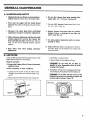
B. Alg_aL'g'_g
A dirty air filter decreases the life and performance
engine and increases fue! consumption
of the
Never'
Ill'
,3 Wash Filter in soap and water
4 Squeeze Filter dry and replace in Cover
Clean the Air Filter:
0 Always after 5 tanks of fuel or 5 hours of operation,
whichever is less.
o More frequently
in dusty conditions,
t, Loosen the two screws on the Air Filter Cover
enough to remove the cover from the engine
ure 2'7,
2
ICAUTION:] Do not clean the air filter in
gasoline or other flammable solvent to avoid
creating a fire hazard.
Fig-
Remove the Air Filter fi'om the Cover, Figure 28_
5 Reinstall the Air Filter Cover, making sure the Choke
exit slot (Figure 28) is placed over the Choke Lever
[_.UTION:]
Fit air filter into the corners of the
housing to keep dust from entering the engine and
causing engine damage, Figure 28.
AIR FILffER
CORNERS
E.,'cJTSl£ff
17
...... r
C, ST_E
, ,,,,,
r,
,,,,_L,I,J,,_,,,,
,,,,,,,,,,,_u
,
,,
:
¸:¸¸¸7¸¸¸
= =
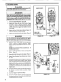
ROPE
Never start the engine with the clutch shroud removed. The
clutch will fly apart and cause serious injury.
CLUTCH
REblOVE SCliEWS
"FLAq[S"
_kW_G
Do not remove the retaining tab and screw to remove
pulley. The spring beneath the pulley is under tension
and can fly out causing serious injury. If any part of the
pulley housing assembly is damaged other than the rope,
do not use the tool. Take it to your Sears Service Center.
i.
Disconnect
Spark Plug Wire_ Figure 29.
2.
Remove the Screw and Nut in the Throttle Trigger
Housing as shown in Figure 5. Hold the Throttle
Trigger away from Drive Shaft Housing and remove
Throttle Cable from Trigger, Pull Cable out of Foam
Grip tunnel
3_ Remove the four Clutch Shroud Screws (Figure 29)
with the small hex wrench provided,
4. Separate the Clutch Shroud from the Engine, Figure 30.
FRONI VIEW
Shown without
Drive Shaft tlousingo
F_re
D_d_'GEBI
_9
Use only a hand tool to remove the clutch. Do not use any
type of motorized tool or std.ke the clutch in any way° Otherwise, the clutch will fly apart and cause serious injury.
Hold the "Flats" of the Clutch with an adjustable
wrench as shown in Figures 30 and 3! (insetL
Remove the Nut counterclockwise with a 3/8"socket
wrench,
5_
NOTE: Clutch will slide offthe crankshaft
not disassemble clutch
.
intact, Do
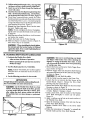
Remove the Beveled Washer, Clutch, and Large Flat
Washer_ Figure 3L
7_ Remove the Pulley Housing from the Engine, Figure 31
8.
Remove Rope Retention Screw Remove any remaining rope.
9.
Hold Pulley Housing as shown in Figure 32. Hand turn
the Pulley c!ockwise as far as it will go. Then, turn the
Pulley counterclockwise
until the Pulley Notch is
aligned with the Housing Notch next to the Retaining
"rab and Screw. Figure 32 Next, turn the Pulley one
complete turn counterclockwise
until the notches are
aligned again_
PULLEY HOUSING
CLUI'CH
LARGE
FLAT
WASHER
10° Insert the small hex wrench into the hole formed by
the Notches to hold the Pulley in position. Figure
32 (inset).
II, Use a 42" length of replacement
Rope
12. Move away ! 0 feet (3 meters) from the fuel tank with
the replacement Rope, Use a match and melt both ends
of' the Rope to prevent fraying
18
F_
3X
BEVELED
WASHER
_CURVES
"I't')WARD
CLUTCH_
.___.M:: ......
13.Pullthemelted
endsthroughathick,cleanragwhile
theRopeis stillhottoobtainsmooth,pointed
ends,
14_Insertoneendof theRopethroughtheHandleand
secure
withaknot,.
15,.InserttheotherendoftheRopethroughtheRopeExit
Hole,intotheinsideoftheHousing,
intothePulley,
andupthroughthePulleyHole,SeeInset,Figure32,
16 Wrap Ropecounterclockwise
aroundthe Pulley
Ratchet
andtucklooseendunderRopewhereitcomes
outofthePulleyHole,Leave a l-inch tail laying flat
!7
18.
t9
20,
on top of the Pulley between the Retainer Rib and the
rope Retention Screw!Post
Figure .32
Reinstall the Rope Retention Screw into the retention post, Tighten until snug.
NOTE: Do not overtighten the Screw, Overtightening the screw can cause the threads in the screw post
to strip out_
Hold Rope taut at Rope Exit Hole so it will not move
and remove hex wrench.
Slowly feed rope into the Pulley Housing
Make sure Spacer is in place as shown in Figure 3t,
then reverse steps to re-assemble
F_tu.e
[CAOTION:] When reinstalling theclutch, tighten
the nut just until the beveled washer is flattened
against the clutch. Over or under tightening the nut
can cause engine damage.
-=-.,--:
D.
, .....
FLE_LE
Lubricate
D1_VE
S_FI'
'_'
.
.,
,
i,,_ .......
,.......
_i '
L_CA_ON
the Flexible Drive Shaft:
-- After each ten (10) hours of operation.
-- Before operating iftbe unit has been stored for
90 days or longer_
e Use Flex Shaft Lube Part No. 530-030102.
NOTE: A tube of"Ftex Shaft Labe'" has been supplied
with your unit to be used after the first 10 hours of
operation
O Use the following procedure
.......
3:_
for best results:
If engine has just been operated, avoid touching the muf1
tier. A hot muffler t_W_D_G
can cause serious burns.
[_U_OH:]
Lay the Flexible Drive Shaft on a clean
surface. Avoid laying the shaft on the floor, ground,
or on any surface that may have dirt or debris. Even
after wiping the shaft, grease residue can pick up
dirt particles that can cause damage or premature
failure.
lCAUTION: [ 'Ihke care to avoid injuring your hands
and fingers with broken wires when checking for
damage or wiping the flexible drive shaft. A cloth
will not prevent the broken wires from puncturing
or tearing your skin.
In Remove the Screw and Nut in the Trottle Trigger Housing as shown in Figure 5o
2., Hold the Trigger' away from the Drive Shaft Housing
and remove the barrel end of the Cable from the Trigger'
as shown in Figure 3.
[CAU'rltON:] Do not Idnk the cable.
3 Pull the Cable from the tunnel in the Foam Grip
4, Loosen (but do not remove) the Hex Screws in the
Clutch Shroud° Figure 1.. Remove the Drive Shaft
Housing fiom the Clutch Shroud°
5. Remove the Flexible Drive Shaft from the Drive Shaft
Housing as shown in Figure 33
6. Check the Flexible Drive Shaft for' broken wires, twists,
or kinks, Replace if damage is found,
7, Using a clean cloth, wipe the surface of the Flexible
Drive Shaft thoroughly to remove any old grease.
Figure 34.
8_ Apply a uniform coat of lube to the entire surface of
the Flexible Drive Shaft,
9_ Inject the remaining contents of the tube into the top
of the Drive Shaft Housing.
10Replace
Flexible Drive Shaft in the Drive Shaft
Housing_
ll.Follow the instructions in 'W_ssembty" to reinstall the
Throttle Cable and the Drive Shaft Housing
19
o This is a complicated
task. It is important
to +btlow insturctions
in sequence as indicated.
Aw o
Make carburetor addustmeats with the driveshaft housing supported to prevent trimmer line from contacting
any object. Hold the tool with your hand. Do not use the
optional shoulder strap for support.
d_'_'AklR_E[_I@
Keep others away when making carburetor
ments.
adjust-
Aw_G
Serious ipjury to the operator and others can occur ifthe
carburetor is not properly adjusted.
® Poor engine performance
can be a result of other
causes such as dirty air filter, carbon build-up
on muffler' outlets, etc. See "Trouble
Shooting
Chart"
before
proceeding
with carburetor
adjustments.
0
The carburetor has been carefully adjusted at the
factory. However, the operator must be sure that
adjustments are made when any of the conditions
occur as mentioned in "Trouble Shooting Sugges+
tions" below.
Very small adjustments
can affect engine performance. It is important to turn the screw a very smalt
amount per adjustment and test performance betbre
making furtheradjustments
Each adjustment should
be no more than the width of the slot in the adjusting
screws
1. TROUB_._
$1I_G
-_U_F.S_ONS
-- Engine will not continue to run at idle position.
See "b:' Idle Speed Adjustment" and "e. Low
Speed Mixture Adjustment"
Trimmer Head continues to spin when the engine
idles. See "b° Idle Speed Adjustment" and "d+
Deceleration Check"
a, 'iurn the Low Speed Mixture Screw and the High
Speed Mixture Screw (Figure 35) clockwise ,just
until they stop Do not turn :he _erewa :mtil they are
tight a5 damage to the needle seats can occut_
Turn the low Speed Mixture and High Speed Mixture Screws one full turn counterclockwise,
Follow instructions "a Preparation,'
High Speed Mixture Adjustment"
through
"f
3.PROCEDUKE
a. PP.EP&R.ATION
1.) Use a fresh fuel mix. See "Fueling Your Engine,'
2 )Make sure the line extends to the length allowed
by the line limiter to provide correct load on
engine
3 )Start the engine Cut grass for 3 minutes to warm
engine '/he engine must be at operating temper_
ature before carburetor'adjustments
can be performed cortectl)'
4, )Stop engine and remove air f'dterby pulling itout
with your fingers, Refer to "Specifications"
for
location,
tX ]IDLE SPEED.A.II)JUST/_IENT
1 )Allow engine to idle,
2 )Adjust Idle Speed Screw (Figure 35) until the
engine continues to run without stalling and
without the trimmer head moving+
Engine diesor hesitates when it should accelerate.
See "c. Acceleration
Check?'
-- Turn screw clockwise to htcrease engine speed
if the engine stalls' or dies°
Loss of cutting power which cannot be corrected
by cleaning the air f'dter. See"f. High Speed Mixture Adjustment:'
-- Ttt rtt screw counterclockwise
to slow enghm
down and/or to keep trimmer head flora
turning°
-- Engine does not return to idle from full throttle
within 2 seconds. See "el. Deceleration Check:'
--Engine
will not run, _
"Trouble
Shooting
Chart" Then, if the carburetor requires adjustment, begin with"2. Basic Carburetor Settings"
,_WA_a_IItbIG
The trimmer line will be spinning during most of this
procedure. Wear your protective equipment and oltr_erve
all safety instructions.
20
N(YI_: In most cases, your _*ngine can be made to
run properly with minor ca_-buretor adjustments,
Refer to "Trouble Shooting Suggestions"
for the
condition you are experiencing and follow the instructions° The basic carburetor settings are provided in
case they are _equired.
3 )Follow instructions in "c Acceleration
and "d, Deceleration Check?'
Check"
4 )No further adjustments are necessary if the
trimmer head does not turn at idle speed and
if performance is satisfactory.
_WAK_IqlNG
Recheck idle speed after each adjustment. The trimmer
head must not turn at idle speed to avoid serious injury
to the operator and others.
L)Allowengine
L)Allow engine to idle
to idle.
2.)Turn the Low Speed Mixture Screw (Figure 35)
slowly clockwise until the speed starts to drop_
Note this position.
2. )Squeeze Trigger fully
a_ If wxformam'e
is satisfactory, proceed to "d.
Deceleration Check."
b. Ifthe engine does not accelerate smootldy,
turn the low Speed Mixture Screw (Figure 35)
counterclockwise
_
a small amount (no
more than the width of the slot in the adjusting
30Turn the Low Speed Mixture Screw counter'clockwise until the speed increases and then starts
to drop again Note this position.
4.)Set the Low Speed Mixture Screw at the m_idpoint between the two positions,
screw),
3 )Repeat step "2)'" until smooth acceleration
obtained
is
NOTE: It may be necessary to repeat "b. Idle
Speed Adjustment" through "c,, Acceleration
Check," to obtain correct adjustments
4 )Follow instructions in "d Deceleration
d. DECE]L,EKATION
L HIGH SPEED _XTURE
CHECK
l.)Allow engine to idle, then squeeze Throttle Trigger fully
1
3_)Release the Throttle Trigger to the idle position
and listen to the deceleration of the engine It must
return to idle smoothly and within I to 2 seconds
a If performance
is satisfactory, proceed to
step "4.)"
b, Ifthe engine slowly or erratically returus to
idle or idles erratically, repeat"b, Idle Speed
Adjustment" or continue through Low Speed
Mixture and High Speed Mixture Adjustments
to obtain proper deceleration
4.)Recheck
Check"
AD_.Js'rbIENT
tCAUTIION:I Do not operate engine at full
throttle for prolonged periods while making high
speed adjustments as damage to the engine
can occur.
Check,"
2.)Allow engine to run at full speed for about
second
5,) Follow instructions in "c_ Acceleration
and "d Deceleration Cheek"
1 )Support the drive shaft housing so the trimmer
line is off the ground and wilt not make contact
with any object.
2 )Allow engine to idle, then squeeze Throttle Trigger fully
NOTE: Perform
at full throttle
steps
"3.)"
through
"5).'
3 ) Turn High Speed Mixture Screw (Figure 35) very
slowly clockwise until engine speed is reduced,
4 )Turn High Speed Mixture Screw very slowly
counterclockwise,
Stop when the engine begins
to run roughly_
5,)Turn the screw slowly the minimum amount
clockwise until the engine runs smoothly,
6,,) Follow instructions in "c. Acceleration
and "d, Deceleration Check"
Check"
idle speed
] If the engine does not operate
according to these instructions alter repeating
the adjusting steps, do not use the tool. Take
it to your Sears Service Center.
[CAUTION:
HIGHSPEED MIXTURE
ADJUSTMENTSCREW LOWSPEED MIXTURE
ADJUSTMENTSCREW
g. REINST&LL
AIR FILTE_
Be sure filter is clean_ See "Air Filter" in the
Maintenance Section for instructions.
IDLE SPEED
ADJUS'I'MFJqT
SCREW
AIR
FILTER
COVER
k"tg,_re 35
[CAIYrION:'] Fit air filter into the corners of the
housing to keep dirt from entering the engine and
causing engine damage. Figure
28.
21
F, S__IE
d_ CAUTION
It is important
to prevent gum deposits from
tbrming in essential fuel system parts such as the
carburetor, fuel filter, fuel hose, or fuel tank during storage.
Experience
indicates that alcohol
blended fuels (called Gasohol or using ethanol or
methanol) can attract moisture which leads to
sepal_tion and tbrmation of acids during storage°
Acidic gas call damage the fuel system of an
engine while in storage.
1° Allow the engine to cool, empty the fuel system, and
secure the tool before transporting or storing.
2. Before storing the too!, use up fuel left in the fuel lines
and carburetol by starting the engine and letting it run
until it stops_
NOTE: If you do not want to remove the fuel from
your unit, SEARS CRAH'SMAN
Puel Stabilizer
(#71-33500) may be added to fuel left in the tank to
minimize gum deposits and acids If the tank is almost
empty, mix stabilizer with fresh fuel in a separate container and add to the tank,
ALWAYS tZOLLOW INSTRUC'HONS
ON THE
STABILIZER
CONTAINER
THEN,
RUN THE
ENGINE
AI
LEAST
2 MINUI'ES
AFTER
STABILIZER IS ADDED TO ALLOW MIXTURE TO
REACH CARBURETOR.
STORE UNIT IN A SAlZE
PLACE. SEE SIEPS 3-5 (this section)
3. Store tool and fuel in an area where fuel vapors cannot
reach sparks or open flames from water heaters, electric
motors or switches, furnaces, etc.
4, Store the tool so the line limiter cannot accidentally cause
injury. The tool can be hung by the drive shaft housing.
5. Store tool out of reach of children.
qJ
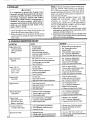
@. '_OUBg2_:
8H_@
_M
........
.i.q
uJ
11
/[I,I.IJJHJ
!CAUSE
........................
REMEDY
,,
,,,,,,
Engine will not start
or will run only for
a few seconds after
starting
1.. Fuel tankempty
2.. Engine flooded
3_ Spark plug not firing
4 Fuel not reaching carburetor_
5. Caxburetor requires adjustment
6. None of the above.
L
2
3
4
5.
6.
Engine will not idle
properly
1. Idle speed set too tast or too slow
2. Low speed mixture requires adjustment
3 Thronle trigger screw too tight
.
None of the above.
l
See "Carburetor Adjustments "'
2 See "'Carburetor AdjustmentsT'
3 Loosen screw to flee trigger
4. C0nta.c!..yourSears Service Cenmr.
Engine will not
accelerate, lacks
power; or dies
under a load
I.
2
3
4.
5,
Engine smokes
excessively
1. Air filter dirty.
2 Fuel mixture incortect.
3. High speed mixture requires adjustment.
Engine runs hot
Fuel mixture incorrect
High speed mixture set too low (lean).
Spark plug incorrect
None of the above.
Air filter dirty_
Spark plug fouled
Carburetor requires adjustment
Muffler outlets plugged,
None of the above.
H,,
..........,H,
1
2.
3.
4.
....,
1,
2
3
4
5.
Fill tank with correct fuel mixture,
See "Starting Instructions"
Install new plug
Clean fuel fdter; inspect fue! line
See "Carburetor Adjustments?'
Contact your Sears Service Center,
Clean or replace air fdter
Clean or replace spark plug and regap
See "Carburetor' Adjustments"
Contact your'Sears Service Center
Contact your Seats Service Center.
1 Clean or' replace air fdter.
2 Refuel with correct fuel mixture
3. See "Carburetor Adjustments."
H, .,.,,H ......
1
2_
3
4.
See "Fueling Your Unit"
See "Carburetor Adjustments.."
Replace with correct plug.
Contact your Sears Service Center.
, .........
Trimmer head turns
at idle speed
1. Carburetor requires adjustment,
2 Throttle trigger screw too tight
3. Clutch requires repair.
'It'immer head
stops under a Ioadfor
does not turn when
engine is accelerated
1 Drive shaft broken or not engaged
2 Carburetor requires adjustments
3 Clutch requires repair.
I Replace or see "'Assembly?'
2, See "Carburetor Adjustments."
3 Contact your Sears Service Center.
Line does not advance
or breaks while cutting
L Line caught between spool and hub.
2. Line improperly wound onto spool.
3. Improper line size.
I. Remove cover.. Check line muting.
2 Rewind spool firmly and evenly.
3 Replace spool
Excessive line usage
L Improper line size,
2, Cutting at high speed around hard objects,
3, C_,_g
line against matedai being cut.
k Use only 080" Sears Laser Line
2, Reduce cutting speed aroundhardobjects..
3, Cut with tip of line.
i i t
22
H .................
_'gART
t
....
I See "Carburetor Adjustments"
2 Loosen screw to free trigger
3. Contact your Sears Service Center.
tilt
,lltjt
......