1
RECORD THIS INFORMATION FOR FUTURE
REFERENCE:
Model Number
Serial Number
ADB Model Number
ADB Serial Number
Date Purchased
USA
SERVICE OFFICE
Dometic Corporation
2320 Industrial Parkway
Elkhart, IN 46516
CANADA
Dometic Corporation
46 Zatonski, Unit 3
Brantford, ON N3T 5L8
CANADA
Roof Top Unit
Description
Air Conditioner
Model
457915
B57915
459516
B59516
540315
540316
640312
640315
Use With Air Distribution Box
Model
Control
3314851.000
Integral Mechanical
For Service Center
Or Dealer Locations
Please Visit:
www.eDometic.com
MODEL
INSTALLATION & OPERATING
INSTRUCTIONS
REVISION A
Form No. 3315079.016 5/13
(French 3315288.013 _A)
©2013 Dometic Corporation
LaGrange, IN 46761
457915.70X
457915.71X
B57915.71X
459516.70X
459516.71X
B59516.71X
540315.70X
540315.71X
540316.70X
540316.71X
Read these instructions carefully. These
instructions MUST stay with this product.
640312.80X
640312.83X
640312C35X
640312C85X
640315.80X
640315.83X
640315.84X
640315C35X
640315C85X
INTRODUCTION
This air conditioner (hereinafter referred to as “unit” or “product”) is designed and intended for installation on the roof of a
Recreational Vehicle (RV) during or after the time it is manufactured.
This unit can be installed by one person with brief help from additional personnel. Use these instructions to ensure a properly
installed, and properly functioning product.
Dometic Corporation reserves the right to modify appearances and specifications without notice.
TABLE OF CONTENTS
INTRODUCTION.....................................................................................................................................................................2
DOCUMENT SYMBOLS.........................................................................................................................................................2
IMPORTANT SAFETY INSTRUCTIONS.................................................................................................................................3
A. Recognize Safety Information....................................................................................................................................3
B. Understand Signal Words...........................................................................................................................................3
C. Supplemental Directives.............................................................................................................................................3
D. General Safety Messages..........................................................................................................................................3
SPECIFICATIONS...................................................................................................................................................................4
A. Table - Unit Data.........................................................................................................................................................4
B. Roof Requirements.....................................................................................................................................................4
INSTALLATION INSTRUCTIONS...........................................................................................................................................5
A. Choosing Proper Location For Unit............................................................................................................................5
B. Roof Preparation........................................................................................................................................................6
C. Wiring Requirements..................................................................................................................................................7
D. Placing Unit On Roof..................................................................................................................................................7
E. Installing Unit..............................................................................................................................................................8
F. Wiring System..........................................................................................................................................................10
G. Installing ADB...........................................................................................................................................................10
OPERATING INSTRUCTIONS..............................................................................................................................................12
A.Controls....................................................................................................................................................................12
B. "OFF" Position ( )...................................................................................................................................................12
C. Cooling Operation (Blue Graphic)............................................................................................................................12
D. Heating Operation (With Electric Heater Option Installed).......................................................................................12
E. Fan Operation (Black Graphic).................................................................................................................................12
F. Center Air Discharge................................................................................................................................................12
MAINTENANCE....................................................................................................................................................................13
A. Air Filter....................................................................................................................................................................13
B. ADB Housing............................................................................................................................................................13
C. Fan Motor.................................................................................................................................................................13
GENERAL INFORMATION....................................................................................................................................................13
A. Frost Formation On Cooling Coil..............................................................................................................................13
B. Heat Gain.................................................................................................................................................................13
C.Condensation...........................................................................................................................................................13
SERVICE - UNIT DOES NOT OPERATE .............................................................................................................................14
WIRING DIAGRAMS.............................................................................................................................................................14
A. Unit Wiring Diagram.................................................................................................................................................14
B. ADB Wiring Diagram................................................................................................................................................15
DOCUMENT SYMBOLS
Indicates additional information that is NOT related
to physical injury.
Indicates step-by-step instructions.
2
IMPORTANT SAFETY INSTRUCTIONS
C. Supplemental Directives
This manual has safety information and instructions to help
users eliminate or reduce the risk of accidents and injuries.
Read and follow all safety information and
instructions to avoid possible injury or death.
A. Recognize Safety Information
Read and understand these instructions before [installing / using / servicing / performing
maintenance on] this product.
This is the safety alert symbol. It is used to
alert you to potential physical injury hazards.
Obey all safety messages that follow this
symbol to avoid possible injury or death.
Incorrect [installation / operation / servicing /
maintaining] of this product can lead to serious injury. Follow all instructions.
B. Understand Signal Words
A signal word will identify safety messages and
property damage messages, and will indicate the
degree or level of hazard seriousness.
The installation MUST comply with all applicable local or national codes, including
the latest edition of the following standards:
indicates a hazardous situation that,
if NOT avoided, could result in death or serious injury.
U.S.A.
indicates a hazardous situation that,
if NOT avoided, could result in minor or moderate
injury.
●● ANSI/NFPA 1192, Recreational Vehicles
Code
●● ANSI/NFPA70, National Electrical Code
(NEC)
CANADA
is used to address practices NOT
related to physical injury.
●● CSA C22.1, Parts l & ll, Canadian Electrical Code
●● CSA Z240 RV Series, Recreational
Vehicles
D. General Safety Messages
Failure to obey the following warnings could result in death or serious injury:
●● This product MUST be [installed / serviced] by a
qualified service technician.
●● Do NOT modify this product in any way. Modification can be extremely hazardous.
●● Do NOT add any devices or accessories to this
product except those specifically authorized in
writing by Dometic Corporation.
3
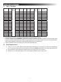
SPECIFICATIONS
A. Table - Unit Data
Model No.
Nominal
Capacity
(BTU HR)
Cooling
Electrical
Rating
120 Vac
60 Hz 1 ph
Compressor Compressor Fan Motor Fan Motor
Rated Load
Locked
Rated Load
Locked
Amps
Rotor
Amps
Rotor
Amps
Amps
Refrigerant
R-410A
(oz)
457915.70X
13,500
12.4
63.0
2.5
5.8
18.0
457915.71X
13,500
12.4
68.0
2.5
5.8
18.0
B57915.71X
13,500
12.4
68.0
2.5
5.8
459516.70X
15,000
13.3
66.0
2.0
459516.71X
15,000
13.3
70.0
2.0
B59516.71X
15,000
13.3
70.0
540315.70X
13,500
12.4
540315.71X
13,500
540316.70X
Minimum
Wire Size*
12 AWG
Copper
Up to 24'
AC Circuit
Protection
***Installer
Supplied
Minimum
Generator
Size**
1 Unit / 2 Units
20 Amp
3.5 kW / 5.0 kW
20 Amp
3.5 kW / 5.0 kW
18.0
20 Amp
3.5 kW / 5.0 kW
5.6
27.5
20 Amp
3.5 kW / 5.0 kW
5.6
27.5
20 Amp
3.5 kW / 5.0 kW
2.0
5.6
27.5
20 Amp
3.5 kW / 5.0 kW
63.0
3.0
8.5
18.5
20 Amp
3.5 kW / 5.0 kW
12.4
68.0
3.0
8.5
18.5
20 Amp
3.5 kW / 5.0 kW
15,000
13.3
66.0
2.8
7.6
29.5
20 Amp
3.5 kW / 5.0 kW
540316.71X
15,000
13.3
70.0
2.8
7.6
29.5
20 Amp
3.5 kW / 5.0 kW
640312.80X
11,000
11.5
53.0
2.6
8.5
20.0
20 Amp
3.5 kW / 5.0 kW
640312.83X
11,000
12.5
63.0
2.6
8.5
18.0
20 Amp
3.5 kW / 5.0 kW
640312C35X
11,000
10.5
53.0
3.5
10.0
19.0
20 Amp
3.5 kW / 5.0 kW
640312C85X
11,000
11.5
53.0
2.6
8.5
20.0
20 Amp
3.5 kW / 5.0 kW
640315.80X
13,500
12.6
63.0
2.6
8.5
18.0
20 Amp
3.5 kW / 5.0 kW
640315.83X
13,500
12.5
63.0
2.6
8.5
19.0
20 Amp
3.5 kW / 5.0 kW
640315.84X
13,500
12.5
63.0
3.5
8.5
19.0
20 Amp
3.5 kW / 5.0 kW
640315C35X
13,500
12.5
61.0
3.5
10.0
17.5
20 Amp
3.5 kW / 5.0 kW
640315C85X
13,500
12.6
63.0
2.6
8.5
18.0
20 Amp
3.5 kW / 5.0 kW
* For wire length over 24 ft., consult the National Electrical Code for proper sizing.
** Dometic Corporation gives GENERAL guidelines for generator requirements. These guidelines come from experiences
people have had in actual applications. When sizing the generator, the total power usage of your RV must be considered.
Keep in mind generators lose power at high altitudes and from lack of maintenance.
*** CIRCUIT PROTECTION: Time Delay Fuse or Circuit Breaker Required.
B. Roof Requirements
●● A 14-1/4″ x 14-1/4″ (±1/8″) square opening (hereinafter referred to as “roof opening”) is required for installing this
unit. This opening is part of the return air system of the unit and MUST be finished in accordance with NFPA 1192.
●● Roof construction with rafters/joists support frames on a minimum of 16 inch centers.
●● Minimum of 1.5 inches and maximum of 6 inches distance between roof to ceiling of RV.
4
INSTALLATION INSTRUCTIONS
A. Choosing Proper Location For Unit
This unit is specifically designed for installation on the roof
of a recreational vehicle (RV). When determining your
cooling requirements, the following should be considered:
●● Size of RV;
●● Window area (increases heat gain);
●● Amount of insulation in walls and roof;
●● Geographical location where the RV will be
used;
●● Personal comfort level required.
1. Normal locations-The unit is designed to fit over
an existing roof vent opening.
2. Other locations-When no roof vent is available
or another location is desired, the following is
recommended:
a. For one unit installation: The unit should be
mounted slightly forward of center (front to
back) and centered from side to side.
b. For two unit installations: Install one unit 1/3
and one unit 2/3’s from front of RV and centered from side to side.
It is preferred that the unit be installed on a relatively flat
and level roof section measured with the RV parked on a
level surface. See table below for maximum acceptable tilt.
Model
Number
Max
Tilt
Model
Number
Max
Tilt
457915
B57915
459516
B59516
15°
540315
540316
15°
640312
640315
8°
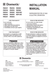
Dimensions Are Nominal
Model
B57915
B59516
12-7/8″
27-5/8″
29-5/8″
18″
Roof Opening
Center Line Of Unit
Front
Keep This Area Free Of Obstructions
FIG. 3
Dimensions Are Nominal
Model
540315
540316
13″
39-5/8″
29-7/8″
18″
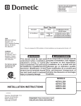
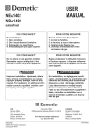
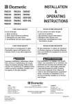
After Location Has Been Selected:
c. Check for obstructions in the area where
unit will be installed. See (FIG. 1), (FIG. 2),
(FIG. 3), (FIG. 4) & (FIG. 5).
FIG. 1
Dimensions Are Nominal
FIG. 2
Center Line Of Unit
Roof Opening
Front
Model
457915
459516
13-1/8″
Keep This Area Free Of Obstructions
34-7/8″
18″
29-7/8″
Roof Opening
Center Line Of Unit
Front
Keep This Area Free Of Obstructions
5
INSTALLATION INSTRUCTIONS
Dimensions Are Nominal
FIG. 4
FIG. 6
Model
640312
640315
23-1/8″
21-1/8″
9-1/2″
40″
2-5/8″
29″
Keep These Areas
Free Of Obstructions
12″
Dimensions Are Nominal
Center Line Of Unit
11-9/16″
3-7/16″
Front
Roof Opening
4″
4″
21-1/8″
Roof Opening
Dimensions Are Nominal
FIG. 5
11-9/16″
3-7/16″
Model
640312C
640315C
2-7/8″
6″
10-3/8″
B. Roof Preparation
40-1/2″
1. FIRE OR ELECTRICAL SHOCK
HAZARD. Verify there are no obstacles inside
RV’s roof and/or walls (wires, pipes, etc.). Shut
OFF gas supply, disconnect 120 Vac power from
RV and disconnect positive (+) 12 Vdc terminal
from supply battery BEFORE drilling or cutting
into RV. Failure to obey these warnings could
result in death or serious injury.
29″
Keep These Areas
Free Of Obstructions
12″
Center Line Of Unit
Roof
Opening
Front
4″
Opening Requirements - Before preparing the ceiling opening, read all of the following instructions before beginning the
installation.
4″
d. Maintain structural integrity.
Otherwise damage to product and/or RV
could occur.
If an existing roof vent opening will NOT
be used a roof opening MUST be cut
through the roof and ceiling of the RV.
This opening MUST be located between
the roof reinforcing members.
The roof must be designed to support 130
pounds when the RV is in motion. Normally
a 200 lb. static load design will meet this
requirement.
e. Check inside the RV for air distribution box
(hereinafter referred to as "ADB") obstructions (i.e. door openings, room dividers, curtains, ceiling fixtures, etc.). See (FIG. 6).
2. Roof vent removal
a. Unscrew and remove the roof vent.
b. Remove all caulking compound around
opening.
c. Seal all screw holes and seams where the
roof gasket will be located. Use a good grade
of all weather sealant.
6
INSTALLATION INSTRUCTIONS
d. If the opening exceeds 14-3/8″ x 14-3/8″, it
will be necessary to resize the opening. See
"B. Roof Requirements" on page (4).
e. If the opening is less than 14-1/8″ x 14-1/8″,
it must be enlarged. See "B. Roof Requirements" on page (4).
3. New opening
a. Carefully mark and cut the required roof
opening. See "B. Roof Requirements" on
page (4).
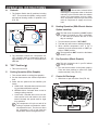
C. Wiring Requirements
1. Route a copper, with ground, 120 Vac supply
wire from the time delay fuse or circuit breaker
box to the roof opening. Use a listed/certified
non metallic - sheathed single strand cable. The
proper size can be determined from chart on
page 4.
If vent fan was removed, the existing wire
may be used provided it is of proper type,
size, location, and correctly fused.
b. Maintain structural integrity.
Otherwise damage to product and/or RV
could occur.
a. This supply wire must be located in the front
portion of the roof opening.
b. The power MUST be on an appropriately
sized separate time delay fuse or circuit
breaker. The proper size protection can be
determined from chart on page 4.
c. Make sure that at least 15″ of supply wire
extends into the roof opening. This insures
an easy connection at the junction box.
d. Protect the wire where it passes into the
opening with approved method.
NEVER create a low spot on
RV roof. Otherwise, water will pool and could
cause a leak.
Using the roof opening as a guide, cut the
matching hole in the ceiling.
The opening created must be framed to provide adequate support and prevent air from
being drawn from the roof cavity. Framing
stock 3/4″ or more in thickness must be used.
Remember to provide an entrance hole for
power supplies at the front of the opening.
See (FIG. 7).
D. Placing Unit On Roof
1. Remove the unit from the carton and discard
carton.
2. LIFTING HAZARD. Use proper
lifting technique and control when lifting product.
Failure to obey this caution could result in injury.
FIG. 7
Place unit on the roof.
Do Not Cut Roof
Structure Or
Rafters
Good-Rafters
Supported By
Cross Beams
3/4″ Min.
3. Do NOT slide unit. Otherwise,
damage to gasket (on bottom of unit) may occur,
and could cause a leak.
Good Location
Between Roof
Rafters
Lift and place the unit over the prepared opening using the gasket on the unit as a guide. See
(FIG. 8).
Frame Opening So It
Won't Collapse When
Bolting Down Unit
FIG. 8
Lift And Place
Leave Access For
Power Supply Wiring
15″ Min. At
Front Of
Opening
Front
Do Not Slide
7
INSTALLATION INSTRUCTIONS
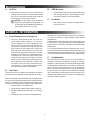
4. Place the ADB kit inside the RV. This box contains mounting hardware for the unit and will be
used inside the RV.
FIG. 11
This completes the outside work. Minor
adjustments can be done from inside the
RV if required.
E.
Installing Unit
1. Check gasket alignment of the unit over the
roof opening and adjust if necessary. Unit may
be moved from below by slightly lifting. See
(FIG. 9).
FIG. 9
Electrical
Cord
Measure Ceiling
Thickness
5. Duct Divider Installation
a. Measure the ceiling thickness. See (FIG. 11).
b. Cut away the number of rows as indicated in
table below. See (FIG. 12).
Center Unit From Below
Ceiling
Thickness
Roof Gasket
# Of
Rows
To Cut
Ceiling
Thickness
# Of
Rows
To Cut
Min.
Max.
Min.
Max.
6.0
6.5
0
3.5
4.0
5
5.5
6.0
1
3.0
3.5
6
5.0
5.5
2
2.5
3.0
7
4.5
5.0
3
2.0
2.5
8
4.0
4.5
4
1.5
2.0
9
FIG. 12
2. Remove ADB and mounting hardware from carton. See (FIG. 10).
Remove Rows
Starting Here
FIG. 10
Duct Divider
Ceiling
Template
c. Carefully install the duct divider in the roof
opening 5-5/8″ from back of roof opening.
See (FIG. 13).
Foil back faces rear of unit.
Control
Box
FIG. 13
Duct Divider
Front
Base Pan
ADB
3. All models in this manual will use a four (4) bolt
pattern for installing the ADB kit.
4. Reach up into the return air opening of the unit
and pull the unit electrical cord down for later
connection. See (FIG. 11).
5-5/8″ From Back
Of Roof Opening
Rear
8
Black Side
To Front
INSTALLATION INSTRUCTIONS
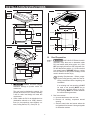
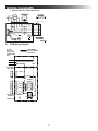
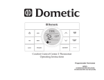
6. Ceiling Template Installation
a. Plug the 6 pin electrical cord from the top unit
into the matching 6 pin connector in the electronic control box. The plug is polarized and
will only fit in one direction. See (FIG. 14).
FIG. 14
FIG. 16
Mounting Bolt
Cable
Connector
Mounting Bolt
Unit Electrical
Cord
120 Vac
Power Supply
Mounting Bolt Pattern Table See (FIG. 17)
Proper Orientation
Of Cable Connector
b. Install supplied non metallic cable connector
in junction box hole cutout. See (FIG. 14) for
proper orientation.
c. Route the previously run 120 Vac power supply wire through cable connector and into
junction box.
d. Secure 120 Vac power supply by tightening
cable connector clamp making sure not to
damage wires. See (FIG. 14).
e. Hold the ceiling template up to the roof opening and line up the channel in the ceiling
template with the previously installed duct
divider. See (FIG. 15).
FIG. 17
Model
Bolt Location
457915
A, D, E & H
B57915
A, D, E & H
459516
A, D, E & H
B59516
A, D, E & H
540315
B, C, F & G
540316
B, C, F & G
640312
B, C, F & G
640315
B, C, F & G
B
C D
E F
G H
A
FIG. 15
Duct Divider
Channel
g. Tighten mounting bolts to
correct torque specifications. Overtightening could damage unit’s base pan or ceiling
template. Not enough torque will allow an inadequate roof seal, and could cause a leak.
f. Hold the ceiling template up to the roof opening and start each mounting bolt, by hand,
through the ceiling template and up into the
unit base pan. See (FIG. 16) & (FIG. 17).
Tighten all four (4) mounting bolts EVENLY
with in 40 to 50 inch pounds. See (FIG. 16).
9
INSTALLATION INSTRUCTIONS
F.
Wiring System
FIG. 19
1. 120 Vac Power Supply Connection
Ceiling Template
Alignment Holes
a. ELECTRICAL SHOCK HAZARD. Verify 120 Vac power is disconnected
from RV. Failure to obey this warning could
result in death or serious injury.
b. ELECTRICAL SHOCK HAZARD. Provide grounding in compliance with
all applicable electrical codes. Failure to
obey this warning could result in death or serious injury.
c. Connect white to white; black to black; using
appropriate size connectors. Secure bare
copper wire under grounding screw in junction box. See (FIG. 18).
FIG. 18
ADB Alignment Holes
FIG. 20
Junction Box
Cover Screw
Junction
Box Cover
ADB Hole
Alignment
d. Tape the connectors to the supply wire to assure they don't vibrate loose.
e. Push the wires into the junction box and install junction box cover. See (FIG. 18).
Hole In Ceiling
Template
Hole In
ADB Cover
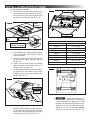
G. Installing ADB
1. Align ADB with ceiling template. See (FIG. 19)
& (FIG. 20).
Front and rear vent doors are supplied
loose. Do NOT install them until all screws
are installed in step 2 & 3.
10
INSTALLATION INSTRUCTIONS
2. Install two (2) (supplied) sheet metal screws inside return air opening to secure ADB to ceiling
template. See (FIG. 21).
3. Install eight (8) (supplied) wood screws inside
the front, rear and side doors to secure ADB to
ceiling. See (FIG. 21).
FIG. 21
FIG. 23
Slot In ADB
2 Sheet
Metal Screws
Return Air
Vent Grille
7. Install the control knobs into the ADB. See
(FIG. 24).
FIG. 24
8 Wood Screws
Knob
4. Install front and rear doors.
5. Place filter in return air vent grille. It may already
be installed on some units. See (FIG. 22).
8. The unit installation is now complete and is
ready for operation. The power supply to the unit
may now be turned on.
9. Verify that all features of the installed system
work. Please read the following operating instructions before attempting to run the unit.
FIG. 22
Filter
Return Air
Vent Grille
6. Install return air vent grille into the ADB. Slide return air vent grille tab into slot in ADB and rotate
up and snap in place. See (FIG. 22).
11
OPERATING INSTRUCTIONS
A. Controls
Wait at least 2 minutes before
restarting the compressor when it has been
manually cycled off with either the selector
switch or the temperature set lever. Otherwise, compressor will quick-cycle and could
result in compressor or supply circuit overload.
1. The Selector Switch has (8) positions including
"OFF". This controls fan speeds, cooling modes
and optional heating modes of operation. See
(FIG. 25).
FIG. 25
Black
Graphic Fan
D. Heating Operation (With Electric Heater
Option Installed).
Colder
The heat mode of operation will NOT replace
a furnace for heating your RV in cold weather. The intent is to remove the chill on cool
days or mornings.
1. Turn the selector switch to "OPT HEAT".
2. The heat strip will come on and begin heating.
3. When desired temperature level in RV is
reached, move the selector switch to "OFF" position or "FAN" position.
Blue Graphic
Cooling
Thermostat does NOT control the fan/heater
ON/OFF cycle.
2. The thermostat controls the compressor On/
OFF operation within a temperature range of
approximately 65° F and 90° F measured at the
ADB inlet.
E.
Fan Operation (Black Graphic)
This will circulate the air in your RV without
cooling or heating.
B. "OFF" Position ( )
1. Turn the selector switch to fan (black graphic).
There are three positions to select from (high,
medium and low). See (FIG. 25).
1. This is to turn unit off.
C. Cooling Operation (Blue Graphic)
1. Turn selector switch to cooling (blue graphic).
2. Set the thermostat at the desired temperature
level.
3. Select the fan speed that best satisfies your
needs:
a. HIGH COOL: Selected when maximum cooling and dehumidification required.
b. MEDIUM COOL: Selected when normal or
average cooling required.
c. LOW COOL: Selected when room is at desired comfort level and needs to be maintained. Normally this speed used for night
time operation.
F.
Center Air Discharge
1. Slide lever to open and close. See (FIG. 26).
FIG. 26
The compressor will cycle on and off as
cooling is required to maintain the selected temperature level. The fan runs when
the compressor is off to help keep the
temperature uniform throughout the RV.
Slide To Open
Or Close
12
MAINTENANCE
A. Air Filter
B. ADB Housing
1. Periodically (a minimum of every 2 weeks of operation) remove the return air filter located behind
the return air vent grille and wash it with soap and
warm water, let dry and then reinstall.
1. Clean ADB housing and control panel with a soft
cloth dampened with a mild detergent. Never
use furniture polish or scouring powders.
C. Fan Motor
NEVER run unit without return air filter in
place. This will plug the unit evaporator coil
with dirt and may substantially degrade the
performance of the unit over time.
1. The blower motor is factory lubricated and requires no service.
GENERAL INFORMATION
Operation on High Fan/Cooling mode will give optimum
or maximum efficiency in high humidity or high outside
temperatures.
Starting the air conditioner early in the morning and giving
it a “head start” on the expected high outdoor ambient will
greatly improve its ability to maintain the desired indoor
temperature.
For a more permanent solution to high heat gain, accessories like Dometic outdoor patio and window awnings will
reduce heat gain by removing the direct sun. They also add
a nice area to enjoy company during the cool of the evening.
A. Frost Formation On Cooling Coil
1. Frost on a small portion of the coil is not unusual. Under certain conditions, ice may form
on the evaporator coil. This is indicated by very
cold output at very low air speed and the icing
can be seen through the air inlet hole with the
filter removed. If this should occur, inspect the
filter and clean if dirty. Make sure air vents are
open and not obstructed. Units have a greater
tendency to frost when the outside temperature
is relatively low. This may be prevented by adjusting the thermostat control knob to a warmer
setting (counter clockwise). Should frosting continue, operate on any FAN ONLY setting until
the cooling coil is free of frost; then resume normal operation. If frost condition persist, contact
your local service center for assistance.
C. Condensation
The manufacturer of this unit will not be responsible for
damage caused by condensation forming on ceilings,
windows, or other surfaces. Air contains water vapor which
condenses when temperature of a surface is below Dew
point. During normal operation this unit is designed to
remove a certain amount of moisture from the air, depending on the size of the space being conditioned. Keeping
doors and windows closed when this air conditioner is in
operation will greatly reduce the chance of condensation
forming on interior surfaces.
B. Heat Gain
The ability of this air conditioner to maintain the desired
inside temperature depends on the heat gain of the RV.
Some preventative measures taken by the occupants of the
RV can reduce the heat gain and improve the performance
of the air conditioner. During extremely high outdoor temperatures, the heat gain of the vehicle may be reduced by:
1. Parking the RV in a shaded area
2. Using window shades (blinds and/or curtains)
3. Keeping windows and doors shut or minimizing
usage
4. Avoiding the use of heat producing appliances
13
SERVICE - UNIT DOES NOT OPERATE
If your unit fails to operate or operates improperly, check
the following before calling your service center.
●● If RV connected to motor generator, check to
be sure motor generator is running and producing power.
●● If RV connected to power supply by a land line,
check to be sure line is sized properly to run
unit load and it is plugged into power supply.
●● Check your fuse or circuit breaker to see if it is
open. Insure fuse is not burnt, or circuit breaker
is "ON" and not activated.
●● After the above checks, call your local service
center for further help. This unit must be serviced by qualified service personnel only.
When calling for service, always give the following:
●● Unit model and serial number found on the
identification label located on base pan of unit
bottom. Return air vent grille must be removed
from ADB to view.
●● ADB model and serial number found on rating
plate located on ceiling template. Observe this
rating plate through the filter opening.
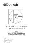
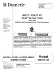
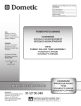
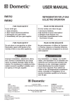
WIRING DIAGRAMS
A. Unit Wiring Diagram
2. 540315 & 540316
1. 457915, 459516, B57915 & B59516
14
WIRING DIAGRAMS
3. 640312, 640312C, 640315 & 640315C
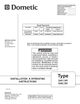
B. ADB Wiring Diagram
9$&
+=3+
86(&233(5
&21'8&7256
21/<
),(/':,5,1*
)$&725<:,5,1*
/,1(63/,&(
:+7
%/.
72237,21$/
(/(&+($7
:+7
*5<
:+7
%/.
/
<(/
+
5('
&
(/(&&211
)520$&
527$5<
6:,7&+
%/8
*51<(/
&
/
+
%/8
7+(50267$7
15