1
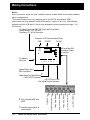
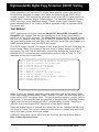
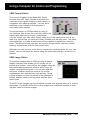
® Model 802 Series Quick Start Guide Index Page AC Power Requirements Please see back cover for complete list of Models and Options covered by this manual. 2 Making Connections 2 Connector Pinouts 3 Normal Front Panel Operation 4 Special Modes and GenOps Image 5 Restoring Normal Operating Mode 6 Using Old Format Naming 6 Digital Friendly and Analog Friendly Modes 7 Cloning Data and Firmware 8 Special Serial Port Modes 9 Setting GBIP Address 9 Format Status Display 10 Self Calibration 10 Temporarily Changing Video Signal Types 11 Temporarily Changing Pixel Depth 11 Testing DDC Compliant Monitors 12 HDCP Testing 13 VGM Software 14 VGM Format Editor 15 VGM Image Editor 15 VGM Sequence Editor and Player 16 This Quick Start Guide is designed to help get you up and running quickly with your generator.. Displaying BMP Bit Mapped Images 17 Uploading New Firmware 19 Developing your own software apps. 19 Model 802 Series Quick Start Guide •1• Making Connections Notes: Some connectors shown are only available on some models and/or with certain hardware option configurations. The current firmware only fully supports use of the RS-232 and optional GPIB communications ports and has limited USB support. Version 3.00 of our VGM software supportsusing the USB port for the bit map download function described on page 17 of this manual. AC Mains Power Inlet (IEC-320 Type) and Power Switch Voltage Range: 100 - 250 VAC Frequency: 50 - 60 Hz Sinusoidal Computer / ATE Communications Ports USB GPIB RS-232 * BNC and Mini-DIN Test Signal Output Connectors 802 Video Test Generator Format Image PC Memory Card Slot Image STEP V ideo R Sync G B ACS Outputs DCS DSS ON Special Frame Sync BNC Connector Digital Video Test Signal Output LVDS or DVI Connector * HD-15 D-Sub (VGA) Test Signal Output Connector * S-Video Color TV Composite Color TV Model 802 Series Quick Start Guide Analog Red Video •2• Analog Green Video as an option on * Available some models. Analog Blue Video Only on Model 802F and 802G. TTL Horiz/Comp Sync TTL Vert Sync * Making Connections VGA Connector Pinout Chart High Density 15 D-Sub Receptacle on all Models Pin # Signal Pin# Signal Pin # Signal 1 Analog Red Video 6 Analog Video Ground 11 No Connection 2 Analog Green Video 7 Analog Video Ground 12 DDC/EDID Serial Data 3 Analog Blue Video 8 Analog Video Ground 13 Horizontal Sync 4 No Connection 9 DDC/EDID +5 VDC Out 14 Vertical Sync 5 Digital Ground 10 Digital Ground 15 DDC/EDID Data Clock DVI Connector Pinout Chart (DVI Options Only) Pin# Signal Pin# Signal Pin# Signal Pin# Signal 1 TMDS D2- 9 TMDS D1- 17 TMDS D0- C1 Analog Red 2 TMDS D2+ 10 TMDS D1+ 18 TMDS D0+ C2 Analog Green 3 D2/4 Shield 11 D1/3 Shield 19 D0/5 Shield C3 Analog Blue 4 TMDS D4- 12 TMDS D3- 20 TMDS D5- C4 Horiz Sync 5 TMDS D4+ 13 TMDS D3+ 21 TMDS D5+ C5 Analog Ground 6 DDC Clock 14 +5 V DC 22 Clock Shield 7 DDC Data 15 Ground 23 TMDS Clock+ 8 No Conn. 16 Hot Plug Detect 24 TMDS Clock- LVDS Connector Pinout Chart (LVDS Option Only) Pin# Signal 1 A 0M Pin# Signal Pin# Signal Pin# Signal 10 DDC Clock 19 A 0P 28 DDC Data 2 A 1M 11 DDC +5VDC 20 A 1P 29 USB Ground 3 A 2M 12 USB+ 21 A 2P 30 USB- 4 Clock 1M 13 USB +5VDC 22 Clock 1P 31 Shield Ground 5 A 3M 14 A 4M 23 A 3P 32 A 4P 6 Shield 15 A 5M 24 No Conn 33 A 5P 7 No Conn 16 A 6M 25 No Conn 34 A 6P 8 No Conn 17 A 7M 26 No Conn 35 A 7P 9 No Conn 18 Clock 2M 27 DDC Ground 36 Clock 2P S-Video Connector Pinout Diagram (Units with TV option Only) C (Chrominance) Ground Y (Luminance) Ground Model 802 Series Quick Start Guide •3• Front Panel Controls and Indicators (Normal Mode) LCD Window Information Vertical Rate nearest Hz Horizontal Rate nearest KHz Current Format Current Test Image Power On Indicator 802 Video Test Generator Format Knob Selects a video signal format from knob list H31 219=VGA_3 V60 198=SMPTE133 Format Image Knob Selects a test image (pattern) from knob list Image Image STEP Image/ Step Button Draws alternate versions of test images Video Gate R G Outputs Sync Gate B Video Gate Buttons Turn individual video elements on or off ACS DCS DSS Sync Gate Buttons Turn different sync types on and off ON Outputs Button Turns all signal outputs on and off Notes: DMT0660 Outline0 NewSeq S1 If the format and image names are shifted to the left side of the LCD the unit is running in a user defined Test Sequence mode from the front panel. Information on creating a Test Sequence using VGM software is on page 16. •4• Model 802 Series Quick Start Guide H31 V60 D4C=DMT0660 1=Outline0 If there is a combination of two letters and a number to left of the equal sign in the top row of the LCD, the unit is in Detailed Status display mode. Information on setting this mode and the meaning of the letters and numbers can be found on page 10. Special Operating Modes and Functions Overview Special Modes Mode _ Remove all modes Set GPIB Address Set baud rate to 9600 Enable programmable keypad Initialize w/factory defaults Calibrate Enable Programming Enable numeric keypad Clone Digital friendly mode Analog friendly mode Enable status display Old format library Hold at power-on _ ACS, DCS, DSS DCS R, DCS R, OUTPUT ACS, DSS R, G, B STEP R STEP, OUTPUT G, B R, B STEP, G, B G Current status _ – 15 2400,N,8,1,N,N OFF – – OFF OFF – OFF OFF OFF OFF Special Key Operations Function _ Toggle analog/digital Rotate video type Set pixel depth DDC-based autoconfig Hold first, press second_ G, B R, B R, G R, ACS Current status _ Analog RGB Color 8 FMT: fmt GenOps Test Image Front panel button combinations are used to select the generator's optional operating modes and special functions. Some are only activated at power up while others are activated once the generator is running. The built-in GenOps test image shows the current status of all options. The upper portion of the image lists the modes that can only be changed on power up and the lower portion lists functions that are selected once the generator is in use. The left hand columns list the names of the modes or special functions. The center columns list the required button combinations and the right hand columns indicate the current status of the mode or function. All of the special modes and functions are described on the following pages. Model 802 Series Quick Start Guide •5• Power up Modes This section describes special operating modes that can only be selected when the generator is first powered up. The indicated buttons are held down and then the unit is powered up. Release the buttons when the LCD displays a message identifying the selected mode. Some operating modes will be retained when the unit is turned off and then powered back on. The only way to deactivate one of these stored modes is to select an alternate mode, remove all modes, or initialize with factory defaults. Remove All Modes Image STEP V ideo Gate R G Use Old Format Names Sync Gate B ACS DCS Outputs DSS ON This button combination resets all operating modes to factory default conditions. This operation does not modify or delete and user data stored in nonvolatile memory. Initialize w/Factory Defaults WARNING: This two step operation erases all user created data stored in nonvolatile memory. The built-in library of video format names has been updated in the current firmware. Many formats found in older firmware are renamed to more closely match nomenclatures used in the display industry or in the appropriate standards. You can use the new names by default or set the firmware to use the names used by older firmware. The use of the older format names is activated by holding down the indicated button on power up. The setting will be retained when the unit is turned off and back on. Image STEP V ideo Gate R G Sync Gate B ACS DCS Outputs DSS ON Step 1: Power up while holding down indicated buttons. Image STEP V ideo Gate R G Sync Gate B ACS DCS Outputs DSS CAUTIONS: ON Step 2: The LCD will display a confirmation request. Press Image STEP to cancel the operation. Press Outputs ON to initialize memory. 1) Switching to using older names will delete all user defined video formats currently stored in the generator. 2) The only way to restore the use of the new format names is to fully reinitialize the generator. This will delete ALL user data stored in the generator. Our VGM software application can be used to back up user data files from the generator to disk and then restore them back to the generator. •6• Model 802 Series Quick Start Guide Power-up Modes Digital Friendly Mode Analog Friendly Mode This operating mode causes the generator to override a given format's analog video output type selection and output digital video. This mode is activated by holding down the indicated buttons on power up. This operating mode causes the generator to override a given format's digital video output type selection and output analog video. This mode is activated by holding down the indicated buttons on power up. Image STEP V ideo Gate R G Sync Gate B ACS DCS DSS Outputs Image ON STEP V ideo Gate R G Sync Gate B ACS DCS Outputs DSS ON This mode will be retained when the unit is turned off and can only be deactivated by Removing all modes, Initializing with factory defaults, or selecting Analog Friendly mode. This mode will be retained when the unit is turned off and can only be deactivated by Removing all modes, Initializing with factory defaults, or selecting Digital Friendly mode. Digital Friendly mode only affects formats loaded using the front panel Format knob. Formats loaded using commands via the communications ports or as part of a Test Sequence are not affected. Analog Friendly mode only affects formats loaded using the front panel Format knob. Formats loaded using commands via the communications ports or as part of a Test Sequence are not affected. You can still use the Toggle Analog/ Digital function to temporarily switch a format's video type to analog when needed. You can still use the Toggle Analog/ Digital function to temporarily switch a format's video type to digital when needed. CAUTION! CAUTION! Enabling Digital Friendly mode on a generator without a digital video option installed will turn off all outputs and report Error 2741 (Digital video type not supported) for every format loaded with the front panel knob. Enabling Analog Friendly mode on a generator that does not have analog video hardware installed will turn off all outputs and report Error 2748 (Analog video type not supported) for every format loaded with the front panel knob. Model 802 Series Quick Start Guide •7• Power-up Modes Clone (Must be exact same model and firmware) 802 Cloning allows you to program a generator at your desk using Quantum Data's VGM software and then easily and quickly transferring the information to other generators of the same PC Card Slot Location model. You transfer (clone) the entire block of battery backed user memory (including video formats, custom test images and test sequences) from one generator to another using a suitable PC memory card. A Type 1, Battery Backed RAM PC card with at least 2 MB of storage is required. Flash or compact type memory cards will not work for cloning. You can use the Archiver function in our VGM software application to transfer entire blocks of user data from a generator to disk files and then upload the blocks of data to other models having similar firmware versions. The Archiver function also supports converting data blocks created with older firmware to be compatible to be uploaded to models with newer firmware. The VGM software also supports saving individual video formats, custom test images and test sequences to disk and then individually uploading them to other models with most other firmware versions. 1. Insert a suitable PC memory card and power up the generator while holding down the indicated buttons. Image STEP Video Gate R G Sync Gate B ACS DCS Outputs DSS ON 2. Release the buttons and then select an operation from the following choices: A. Write to the Card Press the Outputs ON button to write the generator's contents to the card and resume normal operation. B. Read from the Card Press the Image STEP button to replace all previously saved user data stored in the generator's nonvolatile memory with all the data read in from the card. B. Cancel Cloning Press the ACS button to cancel cloning without making any changes and resume normal operation. •8• Model 802 Series Quick Start Guide NOTES: The PC-Memory card can be safely inserted or ejected while the generator is powered up but not actively reading or writing data. The LCD will display text error messages for the following conditions: 1) A memory card is not plugged in when attempting to read or write. 2) Attempting to write to a write protected memory card. 3) Attempting to read data that was created with an incompatible firmware version or corrupted data. You can either correct the condition and use the appropriate Outputs or Image button selection to continue or the ACS button to cancel and resume normal operation with no changes. Power-up Modes Serial Port Configuration Set GPIB Address The default setting of the RS-232 serial port is 2400 Baud, No Parity, 8 data bits, 1 Stop bit, No Handshaking (2400, N, 8, 1, N, N) and normal programming language support. The following special modes can be activated by holding down the indicated buttons on power up and will be retained when the unit is turned off. Generators that have the GPIB (IEEE488) port option installed use two rotary switches for setting the GPIB address. These switches are accessible through the ventilation slots as shown here. Set Baud rate to 9600 Image V ideo Gate STEP R G Sync Gate B ACS DCS Outputs DSS ON Enables normal programming language support at 9600 Baud. Enable numeric keypad Image V ideo Gate STEP R G Sync Gate B ACS DCS Outputs DSS ON Switches protocol to support an optional Model 8020 numeric keypad. The generator stores its current GPIB address in nonvolatile memory. A normal power-up will not update the memory to any new switch settings. The GPIB address is normally read from the switches into memory by holding down the indicated button on power up. Image STEP V ideo Gate R G Sync Gate B ACS DCS Outputs DSS ON Enable programmable keypad Image STEP V ideo Gate R G Sync Gate B ACS DCS Outputs DSS Notes: ON Switches protocol to support an optional 35 key programmable keypad. The current GPIB address is stored in system memory and displayed during power-up. The GPIB address switches are also read into memory if the generator goes through a full re-initialization for any reason. The IEEE-488 configuration description of the generator is: SH1AH1T6TEØLEØSR1RL1PPØDC1DT1CØ Model 802 Series Quick Start Guide •9• Power-up Modes Enable Status Display Calibrate This mode replaces the Format Knob List index number to the left of the format name on the LCD with three characters that show the status of the selected format. It also replaces the Image Knob List index number to the left of the image name on the LCD with image version number. This mode is activated by holding down the indicated buttons on power up. Image STEP V ideo Gate R G Sync Gate B ACS DCS The generator has built-in hardware for calibrating the signal levels of the analog video outputs. No extra hardware or test equipment is required. However, you may obtain slightly better results if three 75 ohm terminators are connected to one set of the Red, Green and Blue outputs. The self calibration operation is initiated by holding down the indicated buttons on power up. Outputs DSS ON Image STEP H31 V60 D4C=DMT0660 1=OutlineO Left Character A Analog Video Format D Digital Video Format Center Digit 4 4 Bits-per-pixel Depth 8 8 Bits-per-pixel Depth Right Character M Monochrome Video C RGB Color Video Y Color Difference Mode Note: The Format test image shows full details of all parameters of a format. • 10 • Model 802 Series Quick Start Guide V ideo Gate R G Sync Gate B ACS DCS Outputs DSS ON The LCD will show a calibration progress report. Any calibration error messages may indicate a hardware problem that requires repair of the generator. The generator will continue to function but may have signal level errors in or more analog outputs. Special Key Functions This section describes special operating functions that can be selected once the generator is operating. These functions operate by holding down one of the indicated buttons while pressing and releasing the other button. If the primary gating function of the held button is inadvertently toggled during the operation, press the button a second time to restore the gating status. Toggle Analog / Digital Video Type Set Pixel Depth Image STEP Image STEP V ideo Gate R G Sync Gate B ACS DCS V ideo Gate R G Sync Gate B ACS DCS Outputs DSS ON Outputs DSS ON Toggles between matching analog and digital video outputs for the current video format. Error 2741 indicates that a matching digital type is not supported and Error 2748 indicates that a matching analog video type is not supported Toggles between pixel depths of 8 bits-per-pixel (up to 256 colors or shades of gray on the screen at one time) and 4 bits-per-pixel (up to 16 colors or shades of gray) Error 2074 indicates the generator hardware configuration does not support the selected pixel depth. Rotate Video Color Type Image STEP V ideo Gate R G Sync Gate B ACS DCS Outputs DSS ON Cycles between RGB color and Monochrome video for formats saved with RGB color for the video type. Cycles between Color Difference, RGB color and Monochrome video for formats saved with Color Difference for the video type. NOTES: Enabling Status Display mode, as described on the opposite page will allow you to see a format's video type settings and pixel depth. Loading another format or reloading the same format will reset the video types and pixel depth to the format's stored settings. Model 802 Series Quick Start Guide • 11 • Special Key Functions DDC Based Autoconfiguration Image STEP V ideo Gate R G Sync Gate B ACS DCS Outputs DSS ON Creates a new format knob list based on video format information stored in the EDID structure of a VESA® DDC compliant monitor attached to the VGA or digital video connector. The generator builds the list by first selecting VESA standard formats from generator's built-in library. The selection is based on the standard formats bits set in the EDID structure. If the EDID structure indicates the monitor has a non-VESA preferred video format, a new video format is created based on the preferred format parameters. The created format's name starts with the three character manufacturer's ID code in the EDID structure and ends with a number based on the number of active lines and refresh rate. The format is saved in user memory and added to the new knob list. The newly created knob list is given a three character name that matches the manufacture's ID code and the list is saved in user memory. Any previ- • 12 • Model 802 Series Quick Start Guide ously created knob list with the same name is overwritten with the new list. The generator will then start using the newly created format knob list. If the generator is powered down in this configuration, it will continue to use the DDC configured format knob list on power up. Pressing the DDC autoconfiguration button combination while using an autoconfigured knob list will always switch to the format knob list named "fmt" (factory default list). Pressing the DDC auto-configuration button combination a second time will trigger a new DDC autoconfiguration cycle. NOTES: The function will report Error 9491 (DDC Not Available) on the front panel LCD if valid DDC data can not be obtained for any reason. The EdidData test image shows a monitor's EDID information. The bottom line of the GenOps test image shows the name of the format knob list currently in use. The factory default format knob list is named fmt. High-bandwidth Digital Copy Protection (HDCP) Testing Video generators with optional DVI digital video outputs contain the required firmware and hardware to support the Intel® Corporation based HDCP downstream protocol. This permits the generator to act as an HDCP signal source for testing HDCP compliant Digital Video displays. The standard firmware includes HDCP Test Keys at no additional charge. Please contact your Quantum Data sales representative if you wish to purchase generators with an optional HDCP Production Key. Test Method HDCP testing with Test Keys uses the HdcpA1B1, HdcpA1B2, HdcpA2B1 and HdcpA2B2 test images. The last four characters in the image name identify which set of Test Keys are used. The HdcpProd image uses the optional production key. You need to make sure you are using a suitable digital video format for the given display under test and that it can correctly show other test images in a stable manner before using the HDCP test image. The HDCP image consists of a screen of text displayed on the unit under test as shown below. When first selected, the test image is output without any HDCP encryption. The text lists the automatic sequencing through the internal and external HDCP communications authentication process with a "Pass" or "Fail" indication at the end of each step. STEP 1: STEP 2: STEP 3: STEP 4: STEP 5: STEP 6: STEP 7: STEP 8: STEP 9: STEP 10: STEP 11: Reset receiver: gate off transmitter clk and data Reset the transmitter and its HDCP engine Read and verify the receiver KSV Write receiver KSV to transmitter At transmitter generate An Write An to the receiver Write the transmitter KSV to the receiver Load the transmitter secret keys Read and compare transmitter Ri with receiver Ri Generate authentication Transmitting encrypted data - Steps 1 and 2 are internal generator setup operations and should always pass. Once downstream authentication steps 3 through 10 pass, the test image will be output using HDCP encrypted video. The entire process repeats if step 9 Fails or if a monitor is disconnected and reconnected to the generator. Selecting another digital video format will restart the HDCP authentication process. Selecting a different test image stops HDCP encryption of the digital signals. Once the authentication is passed, the connection will be reauthenticated every 128 fields of video. The current reauthentication status is shown with additional text in the lower portion of the test image. Additional information about HDCP may be found on the World Wide Web at: http://www.digital-cp.com/ Model 802 Series Quick Start Guide • 13 • Using a Computer for Control and Programming Video Generator Manager (VGM) The VGM software package provides a graphical user interface that allows you to program our Bench Top, ISA card and PCI card Model 801 and 802 Series video generators. You can also use the software to control the generator instead of using the front panel controls. The current version of the VGM runs on Microsoft® Windows® 95/98/NT/2000. The software also allows you to save copies of custom formats, images and sequences on the computer's disk drive. These files can then be uploaded into other Quantum Data video generators. A copy of the VGM software is included on the CD-ROM that comes with each generator sold. The software is also available as a free download from the Tech Support area of our Web site at www.quantumdata.com. The software installation includes on-line help and there is additional documentation in the form of Adobe® Acrobat® PDF files on the CD-ROM. • 14 • Model 802 Series Quick Start Guide Using a Computer for Control and Programming VGM Format Editor The current firmware in the Model 802 Series includes over 200 video formats that match the video and sync signals used by a wide variety of computers and imaging systems. You can store additional video formats in the generator's nonvolatile user memory. The format editor in VGM provides an easy to use interface that allows you to quickly define the signal types and timing for your video format. You can create your own video format using any of the generator's built in formats or a format that you have previously created as a starting point. The editor also allows you to create a new format using a default template as a starting point. The edited formats can then be saved in the generator's battery backed memory and selected with the front panel knob. Although you can use any of the built-in formats as a starting point for your own format, you can not save the format using the same name as any of the built-in formats. VGM Image Editor The custom image editor in VGM provides a simple graphic interface that allows you to quickly set up custom test images. You build up the images using the provided drawing primitives such as dots, lines, triangles, rectangles and ovals. You can also add text and more complex primitives such as full screen crosshatches with user defined line spacing. These custom images can then be saved in the generator's battery backed memory and selected with the front panel knob. The built-in test images can not be edited or used as a starting point for a custom test image. The Model 802's built-in test images use a different method of drawing than used for custom images. Model 802 Series Quick Start Guide • 15 • Using a Computer for Control and Programming VGM Sequence Editor Testing of a given model display may require repeated use of several different formats and images in a specific order. A sequence lets you pair up formats and images to form a single test step. Your create and organize the steps to match your test procedure for a particular display. The 802F and 802G let you manually step forward and backward through such a sequence, or the sequence can continuously cycle through all the steps, stopping for an individually defined time at each step. This mode is useful for burn-in testing or for running displays at trade shows. More than one sequence can be stored in the generator's nonvolatile memory. The number of sequences you can store depends on the sum total of the number of steps in each sequence. A total of about 1280 - 1500 steps can be saved, depending on how many separate sequences are used. VGM Sequence Player Once you have created and stored a sequence stored in the generator, you run it using the VGM software Sequence Player. A future version of the generator firmware may permit an operator to chose and run a stored sequence directly from the front panel of the generator. • 16 • Model 802 Series Quick Start Guide Using a Computer for Control and Programming Instructions for Bitmap Picture Download: The bit map download function in VGM allows you to display, using the video generator, an image stored as a BMP file by your computer. The bit map is transferred directly to the video memory and the color information in the file is transferred directly to the color lookup table memory. Selecting another test image or video format will clear the displayed bit-mapped image. There is no way to store the BMP file in the generator's user memory. NOTE: The bit map download operation does not clear the current displayed test image. It will only over write the portion of active video that matches the size and offset of the downloaded image. The download operation will modify the color lookup table values. This may cause the color to change on other portions of the screen. If you want to start with a blank screen, you should first display the “raster” test image. 1. Requirements to download a bit mapped image file to a generator: - The target generator firmware must support the bit map download function. - The bit mapped image file must be stored on the computer as an uncompressed .BMP file. - VGM must have communications open with the target generator 2. Select Tools -> Image Download from the Main VGM Screen. This will open the Image Download Utility Screen shown here. 3. Select the target generator from the pulldown ”Select a Generator” list. The active video dimensions (in pixels) of the current video format being produced by the generator will be shown in the Screen Dimensions” area of the Image Download screen. 4. You must check the "Serial Option / Use Ymodem" check box when downloading the image via a serial port connection. If you do not put a check in the box, the software will attempt to use a USB connection for the download. The software may stop responding if the box is not checked and there is no USB connection to the generator. Model 802 Series Quick Start Guide • 17 • Using a Computer for Control and Programming 5. You can either type the full path to the bit mapped file you wish to download or click on the “Browse” button. The browse button opens a standard MS-Windows “Open File” dialog box. You can then navigate to the desired file and open it. 6. If you selected a valid BMP file, its dimensions will be indicated in the Image Dimensions area as shown here. 7. You can choose to offset where the downloaded image will be displayed in the active video area. By default the image is drawn start in the top left corner. You can enter horizontal (X) and vertical (Y) offsets of the top left corner of the downloaded images relative to the top left corner of active video. NOTE: The bit map download operation does not clear the current displayed test image. It will only overwrite the portion of active video that matches the size and offset of the downloaded image. The download operation will modify the color lookup table values. This may cause the color to change on other portions of the screen 8. An “OK” message will appear in the status message bar at bottom of the screen if everything is ready for the download to begin. The “Download” button will also be available (not grayed). 9. Click the “Download” button and wait for the image to download and display. Very large bitmap files can take several minutes to load. A message box showing the current download status will be open during the download. There is no way to stop the download process without closing the whole VGM application. • 18 • Model 802 Series Quick Start Guide Using a Computer for Control and Programming Updating Generator Firmware All Model 802 generators can be reprogrammed with new operating system firmware using VGM software. A working copy of the firmware must be in the generator to install new firmware. Please refer to the VGM documentation and help file for information on how to install new firmware. Information on the latest firmware version numbers and file download links can be found on our web site at: http://www.quantumdata.com/downloads/ Advanced Programming Methods All current Models in our 801 and 802 series support a command and query language that allows you to develop your own software application to operate and program the generator. Sample executable and source code files are available from Quantum Data that you can use as a starting point for your application. Please refer to the Programmer's Manual files on the Software and Documentation CD-ROM Model 802 Series Quick Start Guide • 19 • This manual for use with the following Models of Quantum Data Video Generators: 802B, 802F, 802G The following hardware options are covered: - GPIB Communications Port NTSC/PAL TV Outputs (CVSB and S-Video) Single Link DVI Serial Digital Video Outputs Single/Dual Link DVI Serial Digital Video Outputs Low Voltage Serial Digital (LVDS) Video Outputs Information based on the following generator firmware versions: 802F: Version 7.07250000 802B: Version 7.07750000 802G: Version 7.07850000 VGM screen captures and VGM documentation based on: VGM Version 3.00 Entire contents Copyright ©2001 by Quantum Data, Inc. All rights reserved. The information contained in this document is provided for use by our customers and may not be incorporated into other products or publications without the expressed written consent of Quantum Data. Information furnished by Quantum Data is believed to be accurate and reliable. However, no responsibility is assumed by Quantum Data for its use. Quantum Data reserves the right to make changes at any time and without notice to its products to improve performance, reliability, manufacturing methods, and (or) marketability. "Model 802 Series Quick Start Guide" ® Phone: (847) 888-0450 Fax: (847) 888-2802 Toll Free Support in the USA Phone: 1-888-252-6133 Part # 68-00193 Rev. D (23-October-2001) • 20 • Quantum Data, Inc. 2111 Big Timber Rd. Elgin, IL 60123-1100 U.S.A. Model 802 Series Quick Start Guide Internet Connections World Wide Web Site: http://www.quantumdata.com Sales E-mail: [email protected] Customer Service E-mail: [email protected] Technical Support E-mail: [email protected]