1
SIGMA
MRX SERIES
ANALOG AND DIGITAL
MID-SIZE MATRIX ROUTING SYSTEM
OPERATORS MANUAL
SIGMA ELECTRONICS, INC.
P.O. BOX 448
1027 COMMERCIAL AVENUE
EAST PETERSBURG, PA 17520-0448
(717) 569-2681
(MAR’ 03)
UNPACKING
PHYSICAL INSPECTION
Inspect your packages and equipment for any damage that might have occurred during shipping. If damage
has occurred, save the shipping cartons. Report the damage to the shipping company and notify Sigma
Electronics, Inc.
STANDARD SHIPPING CONFIGURATION
Each MRX system will be shipped in multiple cartons. Video and Audio frames are shipped, each in their
own carton, with all modules installed. Power supply frames and the required power supplies are shipped in
the same carton. The accessory box (where this manual was located) containing all power interface cables,
accessories, connectors and documentation is shipped inside the power frame shipping carton.
Control panels ordered with a system are shipped in separate cartons. The external power supply for the
control panel is in the same carton as the control panel.
i
SIGMA MRX SERIES
ANALOG AND DIGITAL MID-SIZE MATRIX ROUTING SYSTEM
OPERATOR’S MANUAL
TABLE OF CONTENTS
UNPACKING .......................................................................................................................................................................................i
PHYSICAL INSPECTION ...............................................................................................................................................................i
STANDARD SHIPPING CONFIGURATION.................................................................................................................................i
TABLE OF CONTENTS.....................................................................................................................................................................ii
INSTALLATION AND OVERVIEW .................................................................................................................................................1
GENERAL OPERATING REQUIREMENTS ................................................................................................................................1
ENVIRONMENTAL ...................................................................................................................................................................1
Ambient temperature/Ventilation.............................................................................................................................................1
Humidity ..................................................................................................................................................................................1
Rack-mounting .........................................................................................................................................................................1
Audio Frame placement ...........................................................................................................................................................1
POWER........................................................................................................................................................................................1
INTERCONNECT WIRING ...........................................................................................................................................................2
AUDIO FRAME - ANALOG .....................................................................................................................................................2
AUDIO FRAME - DIGITAL......................................................................................................................................................2
VIDEO FRAME - ANALOG.......................................................................................................................................................3
VIDEO FRAME - DIGITAL .......................................................................................................................................................3
POWER FRAME .........................................................................................................................................................................3
SYSTEM CONTROL INTERFACE .......................................................................................................................................3
POWER MODULE..................................................................................................................................................................4
REAR SUPPORTS ..........................................................................................................................................................................5
Rear Support Installation Instructions ..........................................................................................................................................5
CONTROL PANEL .........................................................................................................................................................................6
APPENDIX A – SCI PROTOCOL AND INTERFACE................................................................................................................... A1
INTRODUCTION..................................................................................................................................................................... A1
Control Panel Interface.......................................................................................................................................................... A1
Serial Control Interface ......................................................................................................................................................... A1
Vertical Interval Switching ................................................................................................................................................... A1
SCI Configuration Switches.................................................................................................................................................. A1
Control Levels ....................................................................................................................................................................... A1
RS232 PROTOCOL COMMANDS ........................................................................................................................................ A2
SPECIAL COMMANDS .......................................................................................................................................................... A4
RS422/485 PROTOCOL COMMANDS ................................................................................................................................. A6
SERIAL CONTROL AND MODE SWITCHES...................................................................................................................... A7
JUMPER SELECTION............................................................................................................................................................. A8
9 PIN 'D' RS-422/485 WIRING ................................................................................................................................................ A8
9 PIN 'D' RS-232 PIN ASSIGNMENT..................................................................................................................................... A9
RS-232C WIRING .................................................................................................................................................................. A10
APPENDIX B - SPECIFICATIONS ................................................................................................................................................ B1
SYSTEM CONTROL INTERFACE MODULE (MRX-SCI) .................................................................................................. B1
ANALOG VIDEO FRAME (MRX-24V, MRX-32V).............................................................................................................. B1
ANALOG AUDIO FRAME (MRX-24A, MRX-32A) ............................................................................................................. B1
DIGITAL VIDEO FRAME (MRX-DVF)................................................................................................................................. B2
DIGITAL AUDIO FRAME – Balanced (MRX-TDAF) ........................................................................................................... B2
DIGITAL AUDIO FRAME – Unbalanced (MRX-CDAF)....................................................................................................... B3
POWER SUPPLY FRAME (MRX-PSF).................................................................................................................................. B3
MECHANICAL ........................................................................................................................................................................ B3
ii
INSTALLATION AND OVERVIEW
GENERAL OPERATING REQUIREMENTS
ENVIRONMENTAL
Ambient temperature/Ventilation
The MRX Switching System is designed to operate as specified when the ambient temperature is kept
within the range of 0°C to 50°C. Ventilation slots are provided on the front and sides of the frames to assist
in the removal of the excess heat generated in the normal operation of the units. These ventilation slots
must not be blocked. Sigma Electronics will consider blocking of these slots, to be a custom, design
modification by the user. Custom design modifications void the Sigma Electronics warranty.
Humidity
Excessive humidity is harmful to electronic equipment. It is expected that the user will monitor and control
the relative humidity of the operating environment to maintain levels acceptable for the operation of this
equipment.
Rack-mounting
All frames and control panels are intended to be mounted in standard 19” EIA equipment racks. Prior to
installing an MRX Series frame into a rack, the front panel must be removed. To remove the front panel,
grasp the handles and pull firmly away from the frame. The front panel should completely detach from the
ballstuds.
Audio Frame placement
Due to the susceptibility of all audio circuitry to interference from power sources, the audio frame should be
located as far away from power sources as possible.
POWER
The MRX Switching System is designed to operate in all standard commercial power environments
providing input voltage between 100VAC and 240VAC ± 10%. Voltages outside of this range may or may
not be tolerated by the equipment for a period of time but will, in any case, be considered a violation of the
warranty.
1
INTERCONNECT WIRING
AUDIO FRAME - ANALOG
The MRX Analog Audio Switching System is designed to accept both balanced and unbalanced
audio signals having an input level of +26dBu or less in to Hi-Z (+24 dBu into 600Ω). Balanced audio
signals are connected to the audio frame via a 3-wire cable attached to the 3-position, detachable, terminal
block. Unbalanced signals can utilize a 2-wire conductor and connect the ground wire to both the “C” and ““ terminals on the 3-position, detachable, terminal block.
There is an individual connector assigned for each input and output. To achieve termination on the
audio switch module, a load resistor may be added across the terminal block where the incoming wire is
attached.
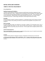
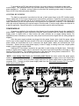
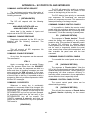
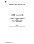
Audio frames can be configured as a full 32x32 matrix or the frame may be partitioned to
accommodate multiple channels. The figure below shows an audio frame configured for a channel of 32x32.
In applications utilizing stereo audio, two 1RU frames are required, one for each channel.
Outputs 1-32 Channel 1
Inputs 1-32 Channel 1
AUDIO FRAME - DIGITAL
Digital audio frames are available in two configurations - the MRX-TDAF for balanced audio signals
(AES-3 1992) and the MRX-CDAF for unbalanced audio (AES-3 ID). Unlike analog audio, where the same
connectors can be utilized for both types of signal, the digital audio frames have different rear panels for
each model. The MRX-TDAF (balanced digital audio) rear panel contains 3-position detachable terminal
blocks to accept a 3-conductor cable and each is terminated with a 110Ω resistor on the PCB. The MRXCDAF (unbalanced digital audio) rear panel contains BNC’s to be used with coaxial cable and are
terminated with a 75Ω resistor on the PCB. There is a separate connector assigned for each input and
output.
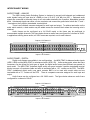
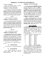
Audio frames can be configured as a full 32x32 matrix. The figure below shows an audio frame
configured for a channel of 32x32.
Outputs 1-32 Channel 1
Inputs 1-32 Channel 1
2
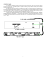
VIDEO FRAME - ANALOG
Video signals are connected to the video frame via BNC jacks on the rear panel. Connect the
source video cables to the corresponding input BNCs on the rear of the frame. The MRX routing switcher
must be the terminating device in the system. All video modules provide the video source with proper 75Ω
termination. All active video outputs must be terminated in 75Ω. (BNC’s for outputs that are beyond the
configured matrix size do not need to be terminated.)
The figure below shows the rear of a system configured as a 32 X 32 switcher. In this configuration,
the bottom two rows of BNC’s are used as the video input connectors. The 32 BNC’s that make up the top
two rows are the video output connectors. All 32 output BNC’s need to be terminated. Use a 75Ω load to
terminate any unused output.
VIDEO FRAME - DIGITAL
Digital video signals are connected to the video frame via BNC jacks on the rear panel. Connect the
source video cables to the corresponding input BNCs on the rear of the frame. The MRX routing switcher
must be the terminating device in the system. All video modules provide the video source with proper 75Ω
termination. All video outputs must be terminated in 75Ω.
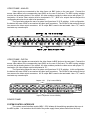
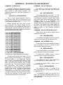
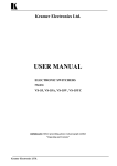
The figure below shows the rear of a system configured as a 32 X 32 switcher. In this configuration,
the bottom two rows of BNC’s are used as the video input connectors. The 32 BNC’s that make up the top
two rows are the video output connectors. All 32 output BNC’s need to be terminated. Use a 75Ω load to
terminate any unused output.
Outputs 1-32
(Top 2 rows of BNCs)
Inputs 1-32 (Bottom 2 rows of BNCs)
POWER FRAME
SYSTEM CONTROL INTERFACE
The system control interface module (MRX - SCI) initiates all the switching operations that occur in
the MRX system. It is located on the left side of the power supply frame (when viewed from the front).
3
To ensure that the SCI has power at all times, the control module is connected to every power
module output. This guarantees that if any functional power supply module is installed, the SCI will have
power supplied to it. In addition, as long as there is more than one operating power supply in the power
frame, the SCI has redundant power capability.
CONTROL BUS WIRING
The data bus connection is provided on the rear of each power frame at the SCI interface panel.
Ribbon cables with 15 Pin D-type connectors are used as Bus connectors. These Bus connectors are used
to transmit the control data from the SCI to all system frames. All systems will be provided with enough bus
cable assemblies to meet the requirements of the system plus an expansion connector. Frame placement
within the racks will determine the required length of the bus cable. If custom length cables are required for
a specific application, Sigma Electronics Inc can accommodate special cable requirements.
POWER MODULE
All power is supplied to the audio and video frames from the power frame through the supplied DC
power cables. Although all power modules are identical, some positions within the frame are dedicated to
supply power to digital audio or video frames and other positions are to supply analog frames. For
applications where redundancy is required, each power frame can hold two digital and two analog assigned
supplies.
After the power supply modules are plugged into the power frame’s slots, install the power cables
into the rear of each supply and then connect to the rear of the appropriate frame, analog or digital. Analog
power cables are terminated with 4-pin connectors and digital power cables are terminated with 6-pin
connectors. Ensure that an analog power supply is used to supply an analog frame and a digital power
supply is used to supply a digital frame.
Additional DC input power connectors are provided on each analog and digital frame. Redundant
analog or digital power supplies may be mounted in the power frame and connected to the audio or video
frames via this connector. The redundant connector on the rear of the analog frame is labeled DC2-I. The
redundant connector on the rear of the digital frame is labeled DC 2.
*NOTE: If one analog video frame and two analog audio frames are used, connect the power supply
cables as follows: Connect one 4-pin power supply cable from the power supply frame to the video frame
connector DC1-I. Connect one 4-pin power supply cable from the power supply frame to the audio frame
connector DC1-I. Connect one 4-pin power supply cable from the video frame connector DC1-O to the 2nd
audio frame connector DC1-I.
TM
Electronics Inc.
4
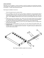
REAR SUPPORTS
Depending upon the installation, it may be necessary to install the included rear mounting frame supports.
These supports are designed to allow connection to rear rails positioned between 19 and 30 inches from the
front supports. To install, follow the directions below.
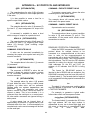
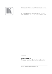
Rear Support Installation Instructions
Refer to illustration below for reference letters.
1. Prior to installation of the frame into the rack, attach an extender bar (A); the flat piece with the
countersunk holes at one end; to each side of the frame using the four (4) supplied #8-32 undercut,
flathead screws (B) through the countersunk holes and into the threaded inserts in the side of the
frame. NOTE: Undercut, flathead screws must be used to provide adequate clearance and proper
fit.
2. Install the frame into the equipment rack, securing the front mounting brackets with the supplied
#10-24 plastic-coated, rack-mounting screws. For shorter front to back rack-mounting applications,
be certain both extender bars are positioned between the vertical, rear mounting rack rails.
3. Install both rear mounting brackets (C) over the end of the extender bars with the angled portion
pointing toward the outside.
4. Secure the rear mounting bracket © to the rear of the rack using #10-24 plastic-coated, rackmounting screws.
5. Install at least one of the supplied #8-32 panhead screws (D) through the extender bar and into the
threaded inserts in the mounting bracket on each side. For greater security, an additional screw
may be installed where possible.
Rear Support Installation (right side only shown)
5
CONTROL PANEL
To initiate the switching operation, data must be input into the SCI. One way to input this data is
through a control panel. The MRX system is capable of utilizing many different control panels available
from Sigma Electronics, Inc.
The data from the control panels is transferred to the SCI via a communication line. References to
this line are typically abbreviated to COMM line. This coaxial cable is connected between either the COMM
1 or COMM 2 BNC on the SCI interface on the rear of the power frame, and the COMM connection on the
rear of the control panel. Both connectors provide an identical interface to the SCI.
Several control panels may be added to the COMM Line as system requirements dictate. Additional
panels are added by installing BNC “T” connectors in the coax path. Coaxial cable paths for either COMM 1
or COMM2 are recommended to be less than 2000 total feet. This coaxial path should NOT be terminated
in a 75Ω load.
TM
Electronics Inc.
6
APPENDICES
be either a composite video signal (1 Vp-p) or a
composite sync pulse (-4vpp). The SCI will use
this reference to determine the vertical interval
switch. If no “REF IN” signal is present the SCI
will execute the switch as soon as it is interpreted.
APPENDIX A – SCI PROTOCOL AND
INTERFACE
INTRODUCTION
SCI Configuration Switches
The SCI serial interface card is the heart of
the Sigma MRX Series mid-size matrix routing
system. The SCI functions as the controller
between the user and the switcher crosspoints. A
switch can be generated one of two ways: by a
remote control panel or by the serial port.
There are three switches located on the front
on the SCI-MRX circuit board. S1 is a momentary
push button switch labeled "RESET". This switch
functions as a microprocessor hardware reset that
forces the processor to restart from a default
setup condition. The SCI will reset all crosspoints,
every output will be set to input 1. An S1 reset will
clear all entries in the internal salvo tables and
panel restrictions in the SCI memory. Reset must
be used with care. Refer to the CTRL-W
command before implementing a system reset
with S1.
The 12-position DIP switch, S2, provides
system configuration. System configuration
includes serial port baud rate, switcher input
range, output range, protocol logical addressing
and number of control levels. Refer to the tables
provided in this manual.
The four-position switch, S3 is used to select
the
Numeric/Alpha
mode,
enable/disable
hardware handshaking and control panel
scanning.
Control Panel Interface
On the rear of the main frame are two BNCs
labeled "COMM 1" and "COMM 2". Coaxial
control lines connect the COMM ports to the
remote control panels. Multiple control panels
may be supported by the SCI. The 64 different
panel addresses allow each panel to have a
unique polling address. This prevents conflicts of
transaction information during a poll between the
SCI and a specific address. The SCI
systematically polls the control panel addresses to
request transaction data. When polled, data
present at the control panel is transmitted to the
SCI via the coax cable. The SCI interprets and
executes the instruction. After a panel is polled,
the SCI transmits an update of the transaction to
all the system control panels. In this way there is
a positive feedback for each transaction.
Control Levels
The SCI-MRX supports four or eight control
levels. Rotary switches on the front of the audio
and video boards control level assignments for
each output group. Level 1, typically assigned to
the video modules, is designated with an A in the
ASCII protocol. Level 2, typically assigned to the
audio modules, is designated with letter B in the
protocol.
The separation of signals into levels allows
the router’s logic to switch one level without
affecting any other level. Using level control
allows the operator to switch a video signal to a
given destination without changing the audio
signal for that destination. This is referred to as a
breakaway switch. As well, the operator may
Serial Control Interface
The second method of control is through the
serial port. The SCI can support either RS-232 or
RS-422 protocols. Selection of RS-232 is
obtained by placing the dual 9 Pin jumper on JP2
(factory default). To select RS-422 the jumper
must be moved to JP1. Serial communications is
achieved with very simple and straightforward
ASCII
commands.
The
interrupt
driven
communications link will respond immediately
whenever a command is issued from an external
serial device. When the command is received, it is
interpreted and executed. The SCI will issue a
response of "OK" to the sending device upon
completion of each transaction. If the command
was invalid the SCI will transmit a "?". The
response can be disabled if required.
source video and audio from two different
source devices. With the use of level control
the video source is preset on its level and
audio is preset on a different level. At the
TAKE command the two different source
signals switch to a common destination. This
is referred to as a split mode switch.
Vertical Interval Switching
The SCI is capable of generating a vertical
interval switch. To do this a reference signal must
be present at the "REF IN" BNC. This signal can
A1
APPENDIX A – SCI PROTOCOL AND INTERFACE
COMMAND: STATUS
RS232 PROTOCOL COMMANDS
Any OUTPUT’s status can be obtained by
entering the following protocol sequence:
The following commands may be issued from
a computer/terminal keyboard or other similar
communication control device. This protocol is
supported by various control systems provided by
other control system manufacturers. Standard
ASCII characters are used to create the command
strings. The SCI-MRX is not case sensitive, and
therefore does not care if capital or lower case
letters are used. Please note that spaces are not
used in any command strings.
Sxxx
The 'S' represents STATUS and the 'xxx'
represents the one to three digit ASCII number of
the OUTPUT. Any leading zeros are optional.
Press RETURN/ENTER to generate execution.
The SCI will respond with the following ASCII
message:
Output xxx, L1 xxx, L2 xxx, L3 xxx, L4 xxx, L5
xxx, L6 xxx, L7 xxx, L8 xxx
This will all print on one line on the terminal
video screen. The 'xxx' will indicate the one to
three digit ASCII number for the OUTPUT and all
the sources for LEVEL 1 to 4 or 1 to 8 in an eight
level system.
COMMAND: Audio-Follow-Video switch
IxxxOxxx
{RETURN/ENTER}
The 'I' represents INPUT and the 'O'
OUTPUT. The 'xxx' represents the one to three
digit number of the respective INPUT and
OUTPUT. Leading zeros are optional. Valid
INPUT numbers for the SCI are 1 to 128. Valid
OUTPUT numbers are 1 to 128. To generate a
TAKE command, press the RETURN/ENTER key
on the keyboard.
When the SCI receives the
request and executes the change, it will respond
with an ASCII message 'OK' (unless disabled see "N/Y" command explanation).
COMMAND: STATUS ALL
A global status can also be generated. This
will give the STATUS for all the active OUTPUTS.
By default, those OUTPUTS not yet addressed
will be indicated as having INPUT 01 selected.
SA
COMMAND: BREAKAWAY
AxxxOxxx
{RETURN/ENTER}
{RETURN/ENTER}
The 'S' represents STATUS and the 'A'
represents ALL.
As always, press the
RETURN/ENTER key to execute the command.
The SCI will respond with the following:
{RETURN/ENTER}
In this command only the requested input
Level (A) will change causing that level to
breakaway from the other levels. The 'A' could
actually be A,B,C,D,E,F,G or H. These eight
letters represent the control levels 1-8
respectively. So an "A" would correspond to
Level 1, a "D" would represent Level 4 and so
on.. The 'Oxxx' is the OUTPUT or destination
number.
L1
xxx
xxx
xxx
L2
xxx
xxx
xxx
L3
xxx
xxx
xxx
L4
xxx
xxx
xxx
L5
xxx
xxx
xxx
L6
xxx
xxx
xxx
L7
xxx
xxx
xxx
L8
xxx
xxx
xxx
OUT
xxx
xxx
xxx
The current INPUT STATUS for all levels of
each OUTPUT will be listed. The number of
outputs to which the SCI DIP switches are set
(see SCI DIP switch settings) will limit the number
of outputs displayed.
COMMAND: SPLIT:
BxxxCxxxOxxx OR DxxxAxxxOxxx
Anytime an invalid or incomplete message is
sent to the SCI, it will respond with an ASCII '?'
unless this response is disabled (see "N/Y"
command). This will occur for each group of
invalid
characters
it
receives.
The
RETURN/ENTER key is the delimiter between
commands. Therefore, invalid characters will not
cause a '?' response until the RETURN/ENTER
key has been sent.
In these examples, the inputs for two levels
are assigned different sources, but both will go to
the same OUTPUT or destination. Again, it is not
necessary to supply the leading zero in assigning
source or destination numbers. B17C03O04 or
B17C3O4 will both perform the same switch.
Order and number of levels does not matter.
Any combination of levels in any order is valid.
For example, D09B21A2C11O9 is a valid
sequence.
A2
APPENDIX A – SCI PROTOCOL AND INTERFACE
COMMAND: MATRIX SETUP REQUEST
The SCI will respond by sending a carriage
return and linefeed to move the cursor on the
screen to the beginning of the next line.
The input/output matrix setup information of
the system can be displayed. To do this, send the
following command:
The SCI always gives priority to commands
over responses. All commands are executed
before any responses are sent. This assures the
fastest processing of a change request.
? {RETURN/ENTER}
The SCI will respond with the following
message:
COMMAND: DISABLE CONTROL PANELS
AVAILABLE OUTPUTS ARE: xxx
AVAILABLE INPUTS ARE: xxx
It is possible to disable the remote control
panels and give exclusive attention to the serial
port for improved response time to incoming serial
commands. To halt the scanning of panels press:
where 'xxx' is the number of inputs and
outputs set at the SCI DIP switches.
PD
COMMAND: DISABLE RESPONSE
{CARRIAGE RETURN}
The response is "Panels Inactive." This will
cause the polling and updating of any remote
panels to stop. This command is especially useful
to improve SCI efficiency in systems where
control panels are not used. Also, this command
can be used to temporarily disable the panel
scan, execute time critical serial transactions, and
then re-enable the panel scan with the next
command.
Responses generated by the SCI can be
disabled with the following command. The
command is:
CTRL-N
This will prevent all SCI responses. No
carriage return is required.
COMMAND: ENABLE RESPONSE
COMMAND: ENABLE CONTROL PANELS
At any time, the responses can be resumed.
The command is:
To re-enable the control panel scan routines
press:
CTRL-Y
PE
Again, no carriage return is needed. Please
note this process differs from the XON/XOFF
routine. In that case, the responses are held in a
buffer and then all pending messages are sent
upon receiving the XON command. In this case,
the messages are simply discarded and no record
of them is kept. In this way, it is possible to tailor a
program to allow only a status response but inhibit
all other SCI messages.
{CARRIAGE RETURN}
The response is "Panels Active." Now the
SCI is fully functional again and the panels will be
updated and polled as before. Careful tailoring of
programming will allow maximum efficiency in
executing serial commands in those applications
where execution time is especially critical.
COMMAND: CONTROL PANEL STATUS
COMMAND: CLEAR ENTRY
The current control panel status can be
determined by pressing:
Whenever a wrong key is accidentally
pressed or a command needs to be changed, the
current command can be cleared by pressing the
SPACEBAR. This is always true as long as the
RETURN/ENTER key has not yet been pressed.
All keystrokes made since the last entry of the
RETURN/ENTER key will be erased. The
CANCEL command is automatic and does not
require the RETURN/ENTER key to be pressed.
The format is:
PS
{CARRIAGE RETURN}
This will yield the response of Panels Active
or Panels Inactive depending on the current
state.
{SPACEBAR}
A3
APPENDIX A – SCI PROTOCOL AND INTERFACE
SPECIAL COMMANDS
COMMAND: HALT DATA TRANSMIT
There are several special commands
available that should be used with care.
The SCI supports the XON/XOFF protocol.
This is a method, through software, of halting and
resuming transmission of data. The XOFF is
activated by holding the Control key and pressing
'S' (CTRL-S). This will halt data transmission..
Incoming commands are still executed during an
XOFF. It is the responses generated by the SCI
that are not sent. They are held in a message
buffer until an XON is received. Like the CANCEL
command, XOFF is automatic and does not
require the RETURN/ENTER key to be pressed.
COMMAND: SYSTEM HARD REBOOT
It is possible to force a system reset from the
serial port, duplicating the function of the RESET
switch on the front of the SCI. All outputs are
reassigned to source 1, all previously stored data
is cleared, all salvo information is erased, and the
system will then reboot as though a power-on
condition occurred. This hard reboot command is:
COMMAND: RESUME DATA TRANSMIT
CTRL - C
XON is activated by holding the Control key
and pressing 'Q' (CTRL-Q). This will resume
transmission of data from the SCI. All pending
responses are sent out the serial port in the same
sequence in which they were received and stored.
Like the CANCEL and XOFF command, XON is
automatic
and
does
not
require
the
RETURN/ENTER key to be pressed.
Note no carriage return is required.
COMMAND: SYSTEM SOFT REBOOT
This is a less destructive reset. This method
will force the internal watchdog timer to restart the
system as though a power-on condition had
occurred. No crosspoint or salvo table information
is lost. Upon this reset the DIP switch settings of
the SCI are read. It is useful to use this reset
command when changing the DIP switches
without requiring a power down of the SCI. This
soft reboot command is:
SALVO COMMANDS
The SCI-MRX is capable of internally storing
ten different salvos. A salvo provides a method of
switching multiple commands at one time. This
“grouping” of switches eliminates delay of
switching from the first step to the last step in a
multi-step switch. There are commands that
pertain exclusively to the creation, edit and
execution of a salvo.
The ten distinct Salvo symbols are as followsSymbol
Keyboard
Command
CTRL - W
Again, no carriage return is required.
COMMAND: CONDENSED STATUS
It is possible to get the status of the system in
a condensed format. There are two possible
methods. The first is in binary and the second is in
packed BCD. The advantage here is a minimal
number of bytes are issued from the port and it is
a very efficient method of gaining the status from
within an external control program. Since these
characters may be non-printing ASCII characters
it is not useful to use in a terminal package.
!
Shift 1
Salvo 1
@
Shift 2
Salvo 2
#
Shift 3
Salvo 3
$
Shift 4
Salvo 4
%
Shift 5
Salvo 5
^
Shift 6
Salvo 6
&
Shift 7
Salvo 7
*
Shift 8
Salvo 8
(
Shift 9
Salvo 9
)
Shift 0
Salvo 10 (EAS)
SHIFT 1 through SHIFT 0 correspond to
salvo 1 through salvo 10. When activating a salvo
the first character in the command must be the
salvo designator symbol; !, @, #, $, %, ^, &, *, (,
or ). The Salvo stored as Salvo 10 will execute
upon a closure applied to the EAS screw
terminals on the rear of the master frame. This
provides an automatic response to an Emergency
Alert System alarm.
The command for a condensed status in
binary is:
SB
{RETURN/ENTER}
The command for a condensed BCD status
is:
SC
{RETURN/ENTER}
For a detailed explanation of the byte
sequence please contact Sigma Electronics
software department.
A4
APPENDIX A – SCI PROTOCOL AND INTERFACE
COMMAND: STORE SALVO
COMMAND: SALVO STATUS ALL
Creating a transaction to be stored in a salvo
is done exactly as a regular transaction except the
salvo symbol is the leading character. The
following example will store this transaction in
salvo 2 (@):
The status of a salvo can be examined by
prefixing the status command with the salvo
symbol.
@A10C3O19 {RETURN/ENTER}
The example provided is for salvo 1 (!). This
example provides the status (S) for all outputs (A).
The difference between a normal status check
and a salvo status check is anytime a level is not
assigned (such as in a breakaway), the
unassigned inputs will display dashes "---" to
indicate these input levels will not be affected by
the salvo. The dashed lines would appear at
levels 3 (C) and 4 (D) of output 16 for the sample
salvo 1 given in the previous command
paragraph.
!SA {RETURN/ENTER}
This is a split mode transaction stored in
salvo number 2 (@ = SHIFT 2),change level 1 (A)
to source ten (10) and level 3 (C) to source three
(3) of output (O) nineteen (19).
Multiple switches may occur upon a single
salvo command. This allows multiple input to
output switches to be preloaded and then switch
simultaneously upon the execution of the salvo. A
typical multiple output salvo would be entered like
the following string of commands;
COMMAND: SALVO STATUS SINGLE OUT
Within each salvo a specific output can be
checked for the status.
! I 01 O 01 {RETURN/ENTER}
! I 02 O 02 {RETURN/ENTER}
! I 03 O 03 {RETURN/ENTER}
! I 04 O 04 {RETURN/ENTER}
! I 05 O 05 {RETURN/ENTER}
! I 06 O 06 {RETURN/ENTER}
! I 07 O 07 {RETURN/ENTER}
! I 08 O 08 {RETURN/ENTER}
! I 09 O 09 {RETURN/ENTER}
! I 10 O 10 {RETURN/ENTER}
! I 11 O 11 {RETURN/ENTER}
! I 12 O 12 {RETURN/ENTER}
! I 13 O 13 {RETURN/ENTER}
! I 14 O 14 {RETURN/ENTER}
! I 15 O 15 {RETURN/ENTER}
! A 16 B 64 O 16 {RETURN/ENTER}
(No spaces are used between any commands.)
#S9 {RETURN/ENTER}
The example command for salvo 3 (#) would
yield the current status (S) for output nine (9).
COMMAND: SALVO ERASE (clear)
There are six commands available to erase a
salvo or portions of a salvo. To erase an entire
salvo use the following command.
$Z {RETURN/ENTER}
In the example above, the command will take
salvo 4 ($) erase (Z) the entire contents:
To erase only a specific output , use the
command with an output limiter attached.
This salvo command is set for Salvo 1 (!) and
switches inputs (I) one to fifteen (1 - 15) to outputs
(0) one to fifteen (1 - 15) respectively. The last
step of salvo 1 performs a split switch of input
level 1 (A) from source sixteen (16) and input
level 2 (B) from source sixty-four (64) to output
(O) sixteen (16). The salvo command is finished
with Return/Enter. The number of possible
transactions in a salvo is equal to the number of
outputs in the system. You can only change each
output once in any particular salvo. Switch
commands do not need to be in numerical order.
If multiple commands are entered for one output,
only the last command for that output will be
visualized after the execution of the salvo.
@Z14 {RETURN/ENTER}
This example for salvo 2 (@) erases (Z) all
input assignments for output fourteen (14).
A range of outputs within a salvo can be
erased as a group.
!Z11-18 {RETURN/ENTER}
This example for salvo 1 (!) erases (Z) all
input assignments for outputs eleven (11) through
(-) eighteen (18).
It is possible to erase only one level of a
salvo. The following command erases only the
level designated for all transactions listed in the
command string.
A5
APPENDIX A – SCI PROTOCOL AND INTERFACE
@ZB {RETURN/ENTER}
COMMAND: EXECUTE PRESET SALVO
The example above for salvo 2 (@) will erase
(Z) all level 2 (B) entries for each output specified
in the salvo.
To execute a preset salvo, choose the salvo
number/symbol of the preset salvo.
$ {RETURN/ENTER}
It is also possible to erase a level for a
specific output within a salvo.
The example above will execute salvo 4 ($),
which was in the preset mode.
#ZC9 {RETURN/ENTER}
COMMAND: CANCEL PRESET SALVO
The example above for salvo 3 (#) erases (Z)
the level 3 (C) input assignment for output nine
(9).
A preset salvo can be canceled.
$Q {RETURN/ENTER}
A command is available to erase a level
within a range of outputs for a particular level.
The sample above takes a preset condition
for salvo 4 ($) and releases (Q, quit) it. This
cancellation of the preset salvo allows normal
transactions to resume.
#ZA12-19 {RETURN/ENTER}
The example above for salvo 3# will erase (Z)
all entries for level 1 (A), beginning with output
twelve (12) through (-)and including output
nineteen (19).
RS422/485 PROTOCOL COMMANDS
COMMAND: EXECUTE SALVO
Unlike the RS232 commands, the RS422/485
protocol allows for multiple devices to be
connected to a computer/terminal at the same
time. In order for the computer/terminal to
communicate with a device in RS422/485, it must
first tell the device to listen. This is the purpose of
the logic address. The SCI has four DIP switches
reserved for setting the device's logic address.
Valid addresses for the SCI are 01-07 (an
address of 00 indicates that RS-232 is being
used).
A salvo can be executed immediately by
choosing the proper salvo symbol and using the
execute command.
!X {RETURN/ENTER}
The example above is the salvo 1 (!) execute
(X) command.
COMMAND: PRESET SALVO
The command to PRESET a salvo, but not
execute it, allows the system to queue a system
for an immediate preloaded switch upon the
execute command.
The format for RS-422/485 protocol is
identical to that of RS232 with one exception. Any
RS422/485 command must be have the prefix of
a forward slash (/). The forward slash is required
on all commands including special commands like
XON/XOFF.
$P {RETURN/ENTER}
The example above for salvo 4 ($) presets
(P) and holds the salvo. During a salvo preset
condition, no other salvo can be accessed.
/xx
The slash (/) is the precursor, and the 'xx' is
the logic address of the device. This is ALWAYS
a TWO DIGIT NUMBER.
Neither edits nor system transactions are
permitted. There are essentially only three
options: execute the salvo, cancel the salvo or
request a status. This is true whether it is a
command from the serial port or a control panel.
All other switch commands are ignored during a
salvo preset.
For example, to generate a typical audiofollow-video switch use the sequence below.
/xxIyyyOzzz {RETURN/ENTER}
The forward slash (/) precedes the SCI's two
digit logic address 'xx', the input number is
represented by one, two or three digits 'yyy' and
the output or destination is represented by the
one,
two
or
three
digit
'zzz'.
A salvo preset has an internal timer of
approximately 30 seconds. If a preset salvo is not
executed within this time, it will automatically be
canceled and a salvo cancel message will be sent
out the serial port.
A6
APPENDIX A – SCI PROTOCOL AND INTERFACE
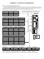
SERIAL CONTROL AND MODE SWITCHES
The system configuration DIP switches S2 and S3 are located on the front edge of the SCI-MRX printed circuit board.
The power supply frame holds the SCI-MRX module. Remove the front panel of the frame to access the switches. The
momentary push-button reset switch S1 is positioned next to S3. See INTRODUCTION for details.
This chart sets the communications Baud Rate.
S2,1
ON
OFF
ON
OFF
S2,2
ON
ON
OFF
OFF
The Dip switch settings below are configured for a 4 level
32x32 matrix using RS-232 protocol at 38,400 baud rate.
Baud Rate
9600
19200
38400
57600
Off [down] / ON [up]
This chart sets the number of switcher inputs (sources).
S2,3
ON
OFF
ON
OFF
ON
OFF
ON
OFF
S2,4
ON
ON
OFF
OFF
ON
ON
OFF
OFF
S2,5
ON
ON
ON
ON
OFF
OFF
OFF
OFF
Input Range
01 - 16
01 - 32
01 - 48
01 - 64
01 - 80
01 - 96
01 - 112
01 - 128
This chart sets the number of switcher outputs (destinations).
S2,6
ON
OFF
ON
OFF
ON
OFF
ON
OFF
S2,7
ON
ON
OFF
OFF
ON
ON
OFF
OFF
S2,8
ON
ON
ON
ON
OFF
OFF
OFF
OFF
Output Range
01 - 16
01 - 32
01 - 48
01 - 64
01 - 80
01 - 96
01 - 112
01 - 128
1
2
3
4
S2,10
ON
ON
OFF
OFF
ON
ON
OFF
OFF
S2,11
ON
ON
ON
ON
OFF
OFF
OFF
OFF
S3
R
E
S
E
T
This chart indicates protocol format and logical address.
S2,9
ON
OFF
ON
OFF
ON
OFF
ON
OFF
S2
1
2
3
4
5
6
7
8
9
10
11
12
Logic Address
RS-232∗
01
02
03
04
05
06
07
Use address 00 for RS-232. All other settings are for RS-422 operation.
Control Level
S2, 12
ON
OFF
Levels
8
4
Control Panel Type
S3,1
ON
OFF
Panel Type
Numeric
Alpha
Handshaking
Reserved
Panel Scan
S3.2
ON
OFF
S3.3
Reserved
S3.4
ON
OFF
Handshaking
Enabled
Disabled
Panel Scan
Scan ALL
Scan Active
NOTE 1 - Fixed serial communications parameters are: 8 Character bits
1 Stop bit
No Parity
NOTE 2 - Synchronous mode switching occurs on line 10 in NTSC and line 7 in PAL when reference is supplied.
A7
APPENDIX A – SCI PROTOCOL AND INTERFACE
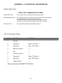
JUMPER SELECTION
SERIAL PORT COMMUNICATION FORMAT
RS-232 SELECTION
JP2, 9 position jumper with header attached, factory default.
RS-422/485 SELECTION
JP1, 9 position jumper, move header from JP2 to this position for RS-422/485.
J4, RS-422/RS-485 selector, factory default is RS-422
J5, Delete for RS-422 and RS-232 (factory default), Add for RS-485
J6, Delete for RS-422 and RS-232 (factory default), Add for RS-485
Reserved Function
JP3, programming interface for U6 (factory reserved)
9 PIN 'D' RS-422/485 WIRING
PIN #
FUNCTION∗
DIRECTION
1
Ground
----
2
Transmit A
Output ( TX Data - )
3
Receive B
Input ( RCV Data + )
4
Receive Common
----
5
N/C
----
6
Transmit Common
----
7
Transmit B
Output ( TX Data + )
8
Receive A
Input ( RCV Data - )
9
Frame Ground
----
∗(Same as standard: ANSI/SMPTE 207M/1984)
A8
APPENDIX A – SCI PROTOCOL AND INTERFACE
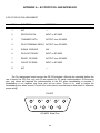
9 PIN 'D' RS-232 PIN ASSIGNMENT
PIN #
FUNCTION∗
DIRECTION
1
N/C
----
2
RECEIVE DATA
INPUT to SCI-MRX
3
TRANSMIT DATA
OUTPUT from SCI-MRX
4
DATA TERMINAL READY OUTPUT from SCI-MRX
5
SIGNAL GROUND
N/A
6
DATA SET READY
INPUT to SCI-MRX
7
READY TO SEND
OUTPUT from SCI-MRX
8
CLEAR TO SEND
INPUT to SCI-MRX
9
N/C
----
The Pin assignments noted are per the RS-232 standard. Although the standard defines the
use of twenty five (25) Pins, only nine (9) are required for PC serial communications. Of those nine
pins, only seven are required for communication to the SCI when handshaking is required. If
handshaking is not required only three pins will be active. There is no need to jumper the
handshaking pins when unused. Consult the control device manufacturer’s data sheet to determine
proper wiring.
PIN OUT
5
9
4
8
3
7
2
6
SCI-MRX Serial Port
A9
1
APPENDIX A – SCI PROTOCOL AND INTERFACE
RS-232C WIRING
SCI-MRX 9 PIN 'D'
PIN
SIGNAL
DESIGNATION
SERIAL PORT
CONNECTIONS
(COMM 1-DCE)
SERIAL PORT
CONNECTIONS
(COMM 2-DTE)
N/C
1-
N/C
N/C
2-
RECEIVE DATA (RXD) [INPUT]
RXD
OR
TXD
3-
TRANSMIT DATA (TXD) [OUTPUT]
TXD
OR
RXD
4-
DATA TERMINAL READY (DTR) [OUTPUT]
CTS
CTS
5-
SIGNAL GROUND
GROUND
GROUND
6-
DATA SET READY (DSR) [INPUT]
RTS
RTS
7-
READY TO SEND (RTS) [OUTPUT]
DSR
DSR
8-
CLEAR TO SEND (CTS) [INPUT]
DTR
DTR
9-
N/C
N/C
N/C
Although the RS-232C standard defines the use of 25 pins, only nine of those are needed for basic PC
serial communications. Of those nine, only seven are required for serial communications with the SCI-MRX.
The above wiring chart is typical for most IBM and compatible type PC's. However, it is always best to check
with the manufacturer's wiring specifications to determine exact pin assignments before beginning. This is
especially true if using COMM 1, since some manufacturers use a 9 pin 'D' connector instead of a 25 pin 'D'.
Regardless of the connector, the signal connections are the same. RXD and TXD are reversed depending
upon whether the serial port is configured as a DTE (data terminal equipment) or a DCE (data communications
equipment).
If the control equipment does not require handshaking, there is no need to jumper the pins on the SCI-MRX. When handshaking
is not required only 3 pins will be used: TXD, RXD and Signal Ground. All other pins will have no connection.
A10
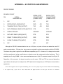
APPENDIX B - SPECIFICATIONS
SYSTEM CONTROL INTERFACE MODULE (MRX-SCI)
Data Transmission System ................................RS-232 & RS-422
Serial Port Baud Rate ........................................Up to 57.6 Kb baud
Control Levels ....................................................Four or eight
Communication Line ..........................................Coaxial, up to 2000 feet
Control Panels ...................................................Up to 64 on 2 Comm. Lines
Number of Salvos ..............................................Four, from Master Control Panel
Protocol .............................................................Simple ASCII, supports Xon/Xoff
External Sync Reference ...................................Composite Sync or Blackburst
Connectors ........................................................(2) BNC for Comm. Line & External Sync.
..........................................................................9 Pin “D” for Serial Port
ANALOG VIDEO FRAME (MRX-24V, MRX-32V)
Input Impedance ................................................75Ω, terminated
Input Level .........................................................1.4V p-p maximum
Input Coupling....................................................DC
Input Return Loss ..............................................35dB minimum to 5MHz
Input DC Offset ..................................................±0.3V
Tilt, field and line................................................<1% maximum
Output Impedance .............................................75Ω, source terminated
Output Level ......................................................1.4V p-p maximum
Output Coupling .................................................DC
Differential Phase ..............................................<0.15° @ 4.43MHz, 10-90% APL
Differential Gain .................................................<0.15% @ 4.43MHz %, 10-90% APL
Frequency Response.........................................±0.1dB from DC to 25 MHz
Bandwidth ..........................................................50 MHz
Input Gain Variation ...........................................<±0.15 dB maximum
Crosstalk ..........................................................>40 dB below 1V p-p @ 5 MHz
Hum & Noise......................................................-65 dB rms., below 1Vp-p
Connectors ........................................................BNC
ANALOG AUDIO FRAME (MRX-24A, MRX-32A)
Input Impedance ................................................30 KΩ, balanced
Input Level .........................................................+24 dBu, maximum
Output Level ......................................................+24 dBu max. into 600Ω
..........................................................................+26 dBu max. into high impedance
Output Impedance .............................................100Ω, balanced
Frequency Response.........................................±0.1 dB 10 Hz to 30 KHz, any level
..........................................................................±0.25 dB to 100 KHz
Hum & Noise......................................................< -90 dBu with 22KHz low-pass filter
Total Harmonic Distortion...................................<0.05% maximum, worst case @ +24 dBu
Crosstalk............................................................90 dB min. below referenced channel 10Hz to 20kHz,
............................................................................... all inputs driven, 600Ω loads. 110 dB typ.
Gain ...................................................................Unity ±0.2 dB, 600Ω termination
Connectors...................................................................... 3 Pin pluggable terminals
APPENDIX B - SPECIFICATIONS
DIGITAL VIDEO FRAME (MRX-DVF)
Signal Type........................................................SMPTE 259M
Connectors ........................................................75 Ohm BNC
Inputs.................................................................32, single-ended, terminated, 800mV p-p
Input return loss .................................................15 dB min. from 5 MHz to 270 MHz
Equalization .......................................................Auto, 750 feet, with Belden 1694A or equiv.
Outputs ..............................................................32, 800mV p-p max. (+/-10%)
Output return loss ..............................................15 dB min. from 5 MHz to 270 MHz
Output DC offset ................................................0.0 V +/- 0.5 V
Rise and Fall time ..............................................0.4ns < tr < 1.50ns, 20% to 80% (rise time)
..........................................................................0.4ns < tf < 1.50ns, 20% to 80% (fall time)
..........................................................................| tr - tf | < 0.5ns (difference of tr and tf < 0.5ns)
Overshoot ..........................................................maximum 10% of total amplitude
Serial Jitter.........................................................500ps p-p max.
Reclocking .........................................................Automatic
Electrical length .................................................11ns typical
Operating temperature.......................................0 to 50 degrees Celsius
DIGITAL AUDIO FRAME – Balanced (MRX-TDAF)
Signal Type........................................................AES-3 1992
Connectors ........................................................3 pin removable terminal block
Inputs.................................................................32, differential, terminated, 7V p-p max.
Transformer Coupled, AES-3 1992
Input impedance ................................................110 ohms (+/-20%) from 0.1 MHz to 6.0 MHz
Input cable length ..............................................500 feet maximum
Outputs ..............................................................32, differential, 7V p-p max. (4.3Vp-p typical)
Transformer Coupled, AES-3 1992
Output impedance..............................................110 ohms (+/-20%) from 0.1 MHz to 6.0 MHz
Output Rise and Fall time...................................5ns < tr < 30ns, 10% to 90% (rise time)
5ns < tf < 30ns, 10% to 90% (fall time)
Serial Data Rates...............................................3.072 Mb/s max. (Fs = 48 kHz max.)
Serial Data Jitter ................................................±20ns p-p max.
Reclocking .........................................................Automatic
Input common mode rejection............................7V peak from DC to 20 kHz
Output common mode noise ..............................30 dB min. below signal from DC to 6 MHz
Electrical length .................................................80ns typical
Operating temperature.......................................0 to 50 degrees Celsius
B2
APPENDIX B - SPECIFICATIONS
DIGITAL AUDIO FRAME – Unbalanced (MRX-CDAF)
Signal Type........................................................AES-3id 1995
Connectors ........................................................75 Ohm BNC
Inputs.................................................................32, single-ended, terminated, 1V p-p max.
Input return loss .................................................15 dB min. from 0.1 MHz to 6.0 MHz
Input impedance ................................................75 ohms from 0.1 MHz to 6.0 MHz
Input cable length ..............................................1000 feet maximum
Outputs ..............................................................32, single-ended, 1V p-p max.
Output return loss ..............................................15 dB min. from 0.1 MHz to 6.0 MHz
Output impedance..............................................75 ohms from 0.1 MHz to 6.0 MHz
Output Rise and Fall time...................................30ns < tr < 44ns, 10% to 90% (rise time)
30ns < tf < 44ns, 10% to 90% (fall time)
Serial Data Rates...............................................3.072 Mb/s max. ( Fs = 48 kHz max.)
Serial Data Jitter ................................................±20ns p-p max.
Reclocking .........................................................Automatic
Electrical length .................................................80ns typical
Operating temperature.......................................0 to 50 degrees Celsius
POWER SUPPLY FRAME (MRX-PSF)
AC Input Voltage................................................100-240 VAC, 50-60 Hz
AC Input Connectors..........................................3 pin IEC (2 total per frame)
Power Supply Type ............................................AC-DC Switching, forced air cooling
Removable Supply Model Name ........................MRX-PSU
Max. Removable Supplies..................................2 in non-redundant configuration
4 in redundant configuration
DC Outputs ........................................................2 per MRX-PSU (8 total per frame)
DC Output Connectors.......................................4 pin for MRX Analog
6 pin for MRX Digital
DC Output Voltage.............................................±18VDC for MRX Analog
Dual +18VDC for MRX Digital
AC Input Power..................................................85W Supplying Maximum Load for MRX Digital
Includes MRX-DVF and MRX-TDAF (or CDAF)
60W Supplying Maximum Load for MRX Analog
Includes MRF-V and two frames of MRF-A
120W Supplying Max. Load for MRX Analog & Digital
Operating temperature.......................................0 to 50 degrees Celsius
MECHANICAL
Switch and Power Frame ...................................1 RU
Master Control Panel (SYX &SYX-3232) ...........2 RU
Single Bus Panels (SBX-32) ..............................2 RU
Alpha-Numeric (ANX) .......................................1 RU
Rapid Take Panel (RTX-32)...............................1 RU
B3
1.75” H x 19” W x 10” D
3.5” H x 19” W x 2.5” D
3.5” H x 19” W x 2.5” D
1.75” H x 19” W x 2.5” D
1.75” H x 19” W x 2.5” D