1
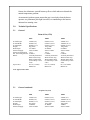
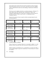
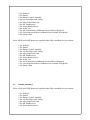
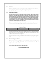
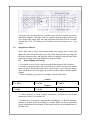
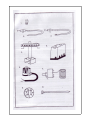
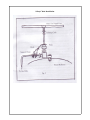
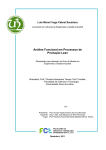
A.B.N 76078600450
A.C.N 078 600 450
P.O.Box 1168
Kangaroo Flat, Vic
3555
Free call: 1800 630116
Email: [email protected]
Internet Address: www.sierraproducts.com.au
Sierra 400N & 400P
Overhead Radiant Cone Heater
(G.C. No. 237. 09)
Sierra 1000N & 1000P
Overhead Radiant Cone Heater
(G.C. No. 36. 237. 09)
Sierra 1500N & 1500P
Overhead Radiant Cone Heater
(G.C. No. 36. 237. 09)
Installation & Servicing Instructions.
This appliance shall be installed in accordance with:
Manufacturer’s installation instructions- Local Gas Fitting Regulations, Municipal Building Codes, AGA
installation code for gas burning equipment (AS5601), Electrical Supply Authority and any other relevant
statutory regulation. This appliance must be installed, serviced and removed by an authorized person.
Contents:
1.0 Introduction
2.0 Technical Specifications
2.1 General
2.2 Ignition & Flame Sensing
2.3 Spark & Flame Electrode Caps
2.4 Thermostat Range
3.0 General Requirements
3.1 Statutory Requirements
3.2 Location of Heaters
3.3 Gas Supply
3.4 Electrical Supply
3.5 Air Supply Ventilation
4.0 On Site Assembly
4.1 Packing
4.2 Assembly of Heaters
5.0 Installation
5.1 General
5.2 Pipe work to Heaters
5.3 Electrical Supply to Heaters
5.4 Suspension of Heaters
5.5 Initial Lighting and Testing
6.0 Servicing
6.1 Removal of Heater
6.2 Sparks & Flame Electrodes
6.3 Pactrol Control
6.4 Solenoid Valve Coil
6.5 Thermostat
6.6 Injector/ Solenoid Valve
6.7 Burner & Emitter
6.8 Mains Input Lead
7.0 Internal Wiring Diagram
8.0 Short Parts List
9.0 Conversion
Additional instruction for Sierra 400P Heater
Additional instruction for Sierra 1000P Heater
Additional instruction for Sierra 1500P Heater
1.0
Introduction
Sierra Overhead Cone Heaters combined ease of installation, economic gas
consumption, excellent all-round heating capability, and outstanding safety
features. The heaters are ideal for use in factories, warehouses, stores, churches,
halls etc. Each heater can be individually set to create any working environment,
and by means of its built in thermostat, maintain these conditions.
The emitter’s high radiant efficiency gives even distribution of radiant heat.
Equable all round temperature is ensured by the shallow profile reflector,
additional warmth being evenly and gently released around it periphery. This
feature also eliminates wasteful intent up flows which otherwise disturb the
natural temperature gradient.
An automatic ignition system means that gas is used only when the heater
operates- no permanent pilot light is needed, so contributing to the heaters
inherent low running costs.
2.0
Technical Specifications
2.1
General
Natural Gas (G20)
Overall height
Overall Width
Overall Depth
Weight
Heater Input
Electrical Supply
Electrical Consumption
Nat. Gas Setting Pressure
Burner
Injector Size
400N
1000N
1500N
610mm (24”)
860mm (34”)
800mm (31.5”)
9kg (20lb)
30.9 MJ/H
240V/ac 50HZ
17VA
0.75KPA
Vertically Positioned
With Cast Iron Top,
With 30 Flame Ports
(4.5mm Deep x 5mm
wide)
No. 42 (2.75mm)
Marked 42
648mm (25.5”)
970mm (38.25”)
895mm (35.25”)
11kg (24lb)
46.8MJ/H
240V/ac 50HZ
17VA
0.75KPA
Vertically Positioned
With Cast Iron Top,
With 40 Flame Ports
(4.5mm Deep x 5mm
wide)
No. 32 (3.30mm)
Marked 32
700mm (30”)
1080mm (42.5”)
980mm (38.25”)
18kg (30lb)
87.5MJ/H
240V/ac 50HZ
17VA
0.75KPA
Vertically Positioned
With Cast Iron Top,
With 40 Flame Ports
(6.0mm Deep x 5mm
wide)
No. 12 (4.80mm)
Marked 12
AGA Approval No. 4964
2.1
General continued.
Propane Gas (G31)
Overall height
Overall Width
Overall Depth
Weight
Heater Input
Electrical Supply
400P
1000P
1500P
610mm (24”)
860mm (34”)
800mm (31.5”)
9kg (20lb)
27.5MJ/H
240V/ac 50HZ
648mm (25.5”)
970mm (38.25”)
895mm (35.25”)
11kg (24lb)
41.4MJ/H
240V/ac 50HZ
700mm (30”)
1080mm (42.5”)
980mm (38.25”)
18kg (30lb)
70MJ/H
240V/ac 50HZ
Electrical Consumption 17VA
Prop. Gas Setting Pressure 2.75KPA
Burner
Vertically Positioned
With Cast Iron Top,
With 30 Flame Ports
(4.5mm Deep x 5mm
wide)
Injector Size
No 54 (1.50mm)
Marked 54
17VA
2.75KPA
Vertically Positioned
With Cast Iron Top,
With 40 Flame Ports
(4.5mm Deep x 5mm
Wide)
No. 50 (1.9mm)
Marked 50
17VA
2.75KPA
Vertically Positioned
With Cast Iron Top,
With 40 Flame Ports
(6.0mm Deep x 5mm
Wide)
No. 42 (2.40mm)
Marked 42
AGA Approval No. 4964
2.2
Ignition & Flame Sensing (full Sequence Control)
Patrol controls type CS01-12. Pre-purge of ten seconds followed by a trial for
ignition of ten seconds. Control will shut down and lock out following an
unsuccessful ignition attempt. One attempt at re-ignition will take place following
loss of detected flame.
2.3
Spark & Flame Electrode Gaps
2.5mm to 4mm
2.4
Thermostat Range
0*C to 50*C (32*F to 122*F)
3.0
General Requirements
3.1
Statutory Requirements
It is the law that all gas appliances installed by authorized persons in accordance
with the AS5601. Failure to install appliances correctly could lead to prosecution. It
is in your own interest, and that of safety, to ensure that the Law is complied with.
3.1
Statutory Requirements continued.
The installation must be completed in accordance with these instructions, and the
relevant requirements of the National and Local Building Regulations, the
Electrical Supply Authority and any other relevant statutory regulation.
Note: The installation code AS5601 is specifically referred to in Government
Legislation in some states.
3.2
Location of Heaters
The locations chosen for the heaters must permit a satisfactory means of support,
and provide adequate space for service access, and must be clear of any sprinkler
system, overhead crane or other areas where damage or interference to the heater
may occur.
The heaters must be sighted so that there is a minimum clearance of 400mm (16”)
above, and one meter (40”) sideways, and 2.5 meters (98.5”) below. Any
combustible material adjacent to a heater must be shielded so that its temperature
does not exceed 50*C. Refer to AS5601 PAGE 137, for definitions of noncombustible material.
Determine the number of heaters required, and their mounting heights from the
following guidelines:Building Type
Suspension Height
M2
ft
Heater Spacing
M2
Sierra 400N & 400P
ft
Area Heated by each
Heater
M2
ft
Well insulated building
of modern construction.
Limited air changes
Poorly insulated
building and/ or
excessive air changes
3.8
12.5
3.8
12.5 5 to 6
Well insulated building
of modern construction.
Limited air changes
Poorly insulated
building and/ or
excessive air changes
4.25
14 9 to 11
30 to 35
90
1000
4.25
14 7.5 to 9
25 to 30 65
700
Well insulated building
of modern construction.
Limited air changes
Poorly insulated
building and/ or
excessive air changes
6.5
22 11 to 12
35 to 40 140
1500
6.5
22 9 to 11
30 to 35 102
1100
6 to 7
19.5 to 23
42
450
16.5 to 19.5 30
320
Sierra 1000N & 1000P
Sierra 1500N& 1500P
3.2
Location of Heaters continued
Heaters should not be positioned directly over personnel working in a static
position, and not closer than 3mts (10ft) to the roofs of internal offices or stores.
When the heaters are intended for use as spot heating, or in open areas where a
lower mounting height is required, the manufacturer or Sierra Products P/L should
be consulted.
3.3
Gas Supply
An existing meter should be checked, preferable by an authorized person, to
ensure that the meter is adequate to deal with the rate of gas supply required.
Gas supply line and meter must be of adequate size and installed in accordance
with the requirements of AS5601 and the local gas authority. The heater gas inlet
point is located on the vertical centerline 45mm above the radiant reflector cone.
(See figure 1.)
Complete installation must be tested for soundness as described in the above
standard.
3.4
Electric Supply
Electrical wiring to the heater must be installed by a licensed electrician in
accordance with the relevant requirements of the SAA Wiring Rules AS 30001991 and any local service rules:“WARNING- THIS APPLIANCE MUST BE EARTHED”
3.5
Air Supply and ventilation
The heater is designed as a flueless appliance, and therefore can only be installed
where the ratio of room volume to gas consumption complies with the
requirements of AS5601.
In all cases there must be provision for an adequate supply of air for both
combustion and general ventilation. If the total input of the appliance does not
exceed 3mj/h per cubic meter of room/ enclosure volume, the required air may be
provided by adventitious openings, i.e. gaps around doors, windows etc.
If it is necessary to provide room ventilation openings, or mechanical ventilation,
this shall be done in accordance with the requirements of AS5601. Detailed
recommendations for air supply are given on page 72 of the AS5601.
3.6
Warning:
1. Do not place articles on or against this appliance.
2. Do not use or store flammable materials near this appliance.
3. Do not spray aerosols in the vicinity of this appliance while it is in operation.
4.0
On Site Assembly
4.1
Packing.
Sierra 400N and 400P heaters are supplied either fully assembled or in two cartons.
1 No. Reflector
1 No. Emitter
1 No. Burner/ Control Assembly.
1 No. Gas Feed Pipes with Unions
1 No. Main Connection Lead
3 No. M6 Thumbscrews
1 No. Socket Headed Screw
4 No. Nylon Ties
1 No. Set of Instructions (Additional Sets Available if Required)
1 No. Users Instruction Sheet (Additional Sets Available if Required)
1 No. Safety Chain.
Sierra 1000N and 1000P heaters are supplied either fully assembled or in two cartons.
1 No. Reflector
1 No. Emitter
1 No. Burner/ Control Assembly.
1 No. Gas Feed Pipes with Unions
1 No. Main Connection Lead
3 No. M8 Thumbscrews
1 No. Socket Headed Screw
4 No. Nylon Ties
1 No. Set of Instructions (Additional Sets Available if Required)
1 No. Users Instruction Sheet (Additional Sets Available if Required)
1 No. Safety Chain.
4.1
Packing continued.
Sierra 1500N and 1500P heaters are supplied either fully assembled or in two cartons.
1 No. Reflector
1 No. Emitter
1 No. Burner/ Control Assembly.
1 No. Gas Feed Pipes with Unions
1 No. Main Connection Lead
3 No. M8 Thumbscrews
1 No. Socket Headed Screw
4 No. Nylon Ties
1 No. Set of Instructions (Additional Sets Available if Required)
1 No. Users Instruction Sheet (Additional Sets Available if Required)
1 No. Safety Chain
4.2
Assembly of Heaters
1. Stand heater vertically with emitter at the top.
2. Position reflector over conical emitter, and align three fixing holes with emitter
suspension brackets. Insert and tighten three thumbscrews to attach reflector to
emitter.
3. Tilt heater so that it rests on the reflector rim with union connection to solenoid
valve uppermost. Position gas feed pipe above reflector, and connect union nut a
few turns to mate with solenoid valve.
4. Insert socket headed screws through die-casting into centre of reflector top.
Tighten moderately.
5. Tighten union with suitable spanner.
5.0
Installation
5.1
General
Reference should be made to sections 3.2, 3.3, 3.4, and 3.5 for location of heaters,
gas supply piping, electrical wiring and air supply respectively.
5.2
Pipe Work to Heaters
Run gas supply lines above proposed position of heaters, and provide dropped
lengths in ½ inch BSP mild steel pipe to each heater. As approved service cock
must be fitted before each pipe drop to enable the heater gas supply to be isolated
for servicing. Support the pipe work adjacent to the ½ inch BSP dropped lengths.
This support, by straps, chain or clamps, should be fitted directly to the structure
of the building e.g. roof truss. It should be of sufficient strength to take the weight
of the heater without sagging of the pipe work.
The lower end of each dropped length should be as tabulated, above floor level.
Sierra 400N & 400P
M 3.8
Ft 12.5
Suspension Height.
Sierra 1000N & 1000P
M 4.25
Ft 14
Sierra 1500N & 1500P
M 6.5
Ft 22
Slip the ring of the safety chain over the threaded end of the ½ mild steel dropped
length, and screw on union supplied with each heater. Install the heater and
connect safety chain as shown in figure 2.
Important: Pressure test the gas installation for soundness, and purge the supplies
of air.
5.3
Electrical Supply to Heaters.
The heater (s) must be supplied from a separate final sub- circuit protected by an 8
amp fuse or circuit breaker. The “Users Instruction Sheet” must be affixed
adjacent to the control switches.
NOTE: THIS APPLIANCE MUST BE EARTHED.
Typical Installation Wiring
The heaters may be controlled by a suitable time switch if required (see above
installation diagram). Using the cable ties supplied, strap the supply flexible cord
to its dropped gas supply pipe and either terminate the flexible cord in a suitable
junction box or fit a 3 pin plug to the flexible cord and terminate it in a 3 pin
socket.
5.4
Suspension of Heaters.
Secure hook end of safety chain around heater arm (supply pipe). Attach and
tighten the union nut at the heater top to the union. Insert the three pin plug into
the heater thermostat box, and using the cable ties supplied, strap the main leads
to the gas feed pipe on the side facing away from the emitter.
5.5
Initial Lighting and Testing.
1. Turn on the service cock to each heater and set thermostat(s) fully clockwise.
2. Switch on electrical supply, and override the time switch if necessary to enable
heaters to ignite. Should any heater fail to ignite because of air in the gas supply
pipes, interrupt the electrical supply for twenty seconds to allow a further ignition
attempt.
3. Check and adjust gas pressure in accordance with the table below.
Sierra 400N
0.75 KPA
Sierra 400P
2.75 KPA
Natural
Sierra 1000N
0.75 KPA
Propane
Sierra 1000P
2.75 KPA
Sierra 1500N
0.75 KPA
Sierra 1500P
2.75 KPA
4. Allow premises to reach required temperature, and then set each heater
thermostat so that is just switches off.
5. Set time clock to customer’s requirements, ensuring that ‘on’ Periods start three
quarters of an hour before the building is occupied. Make sure that a responsible
person understands the functioning of the heaters and the use and adjustments of
the time clock.
6. Check that the “User Instruction Sheet” is permanently fixed adjacent to the
heaters on/ off switch.
Advise the user or purchaser that, for continued efficient and safe operation of the
heaters, it is important that adequate servicing is carried out at intervals
recommended by the Local Gas Authority.
If the heater cannot be adjusted to perform or operate correctly, contact the
authorized service agent in your state.
6.0
Servicing
It is recommended that servicing of the appliance be carried out prior
commencement of each heating season and must be carried out by an authorized
person.
Important note: in the interest of safety, it is recommended that the heater(s) be
removed and put on a bench for servicing. It is advised to invert the heater over a
shallow cardboard box for the majority of servicing operations. Always check for
gas soundness after servicing of the heaters.
WARNING: ISOLATE
MAINTENANCE.
6.1
POWER
SUPPLY
BEFORE
ATTEMPTING
To Remove Heater from Suspension Pipe.
1. Disconnect the electrical supply to heater(s).
2. Disconnect mains cable from junction/ box plug socket leaving high
temperature mains cable on heater in place.
3. Turn off the gas at the service cock, and disconnect the heater at the union
cock, taking precautions to adequately support its weight.
4. Unhook the safety chain.
Note: use only a high temperature type of plastic tie or metal buckle when
replacing heater- a suitable clip is 10 x MC6.
6.2
To Remove Spark or Flame Electrode
1. Disconnect electrode wires from (terminal 1 spark) and (terminal 4 flame) on
Pactrol base.
2. Using stubby screwdriver, undo and remove retaining screw.
3. Remove electrode from bracket by pulling downwards.
4. To replace electrodes reverse above procedure.
Note: after replacing electrode. Check there is a gap of 2.5 to 4mm between
electrode top and burner flame port face. Do not cross electrode leads when
replacing.
6.3
To Remove Pactrol Full Sequence Control.
1. Fully loosen the two plastic headed screws holding control to base.
2. Carefully pull off control from base.
Note: when replacing control ensure that all rubber grommets are correctly
positioned in mounting base. Do not over tighten plastic headed screws.
6.4
To Remove Solenoid Valve Coil.
1. Remove pactrol control as described above.
2. Disconnect solenoid valve wires from terminals 3, 5 and 7 of pactrol base.
Remove cable retaining tie and rubber grommet.
3. Remove circlip washer from top of coil and remove coil from solenoid body.
Note: when replacing coil refit rubber grommet and “new” cable tie. Ensure that
the coil lead length is a maximum of 250mm, and that the lead entry to coil is
positioned away from burner pan. This is to prevent coil lead from touching
burner pan.
6.5
To Remove Thermostat
1. Remove (4) M3 screws holding cover to thermostat box.
2. Pull off receptacle connection from thermostat.
3. Remove screw and clip holding phial to underside of box.
4. Pull off thermostat knob and undo two screws holding bezel and thermostat.
Note: when replacing thermostat ensure that connections are made to terminals
“1” and “2” and that thermostat capillary tube is well clear of electrical
connections. Also ensure bezel is refitted incorrect position pointer mark at
bottom. (See Fig 1.)
6.6
To Remove Injector/ Solenoid Valve Assembly
1. Remove circlip washer from top of solenoid valve coil, and remove coil from
solenoid body.
2. Undo union adjacent to solenoid valve.
3. Undo 2 socket headed screws using 5mm Allen Key, holding die cast injector
holding to burner pan.
6.7
To Remove Burner and/ or Emitter.
1. Remove injector/ solenoid valve assembly as described above.
2. Remove screws attaching spark/ flame electrodes to burner pan.
3. Undo two socket headed screws using 5mm Allen Key, holding burner pan to
burner and takeaway burner pan from heater.
4. Turn heater over, and remove three thumbscrews holding reflector to emitter.
5. Using a 13mm Spanner, undo the hex headed setscrew and remove the clamp
plate holding the emitter to the burner.
Note: Re-assembly is a reverse of the above, when replacing burner pan ensure
that the pactrol is on the same side of the burner as the two electrodes.
Re-check electrode gap- (Refer to C1.6.2)
6.8
Main Input Lead
The mains input lead consist of 3 meters (10ft) of 3 core flexible EPR/CSP having
cross sectional area of 0.75mm2 and a continuous operating temperature rating of
85*C.
Note: this mains lead must not be replaced by a cable having a lower temperature
or current rating.
7.0
Internal Wiring Diagram
8.0
Short Parts List
Manufacturers:
Sierra Products P/L
P.O.Box 1168
Kangaroo Flat Vic 3555
Appliance Name and Model No.
Key No. Description
1
2
3
4
5
6
7
8
9
8.0
Injector (natural gas) No. 42 (2.75mm)
Flame Electrode with Lead
Spark Electrode with Suppression Lead
Burner Complete with Electrode Bracket
Pactrol CSS01-12
Solenoid Valve Coil
Thermostat
Thermostat Knob
Cable Ties
Sierra 400N
No. Off
1
1
1
1
1
1
1
1
4
Key No. Description
Injector (natural gas) No. 32 (3.30mm)
Flame Electrode with Lead
Spark Electrode with Suppression Lead
Burner Complete with Electrode Bracket
Pactrol CSS01-12
Solenoid Valve Coil
Thermostat
Thermostat Knob
Cable Ties
Sierra 1000N
No. Off
1
1
1
1
1
1
1
1
4
Appliance Name and Model No.
Key No. Description
1
2
3
4
5
6
7
8
9
2065
4549
4600
2045
4194
2794
3108
3109
3107
Short Parts List continued
Appliance Name and Model No.
1
2
3
4
5
6
7
8
9
Makers Part No.
Injector (natural gas) No. 12 (4.80mm)
Flame Electrode with Lead
Spark Electrode with Suppression Lead
Burner Complete with Electrode Bracket
Pactrol CSS01-12
Solenoid Valve Coil
Thermostat
Thermostat Knob
Cable Ties
Makers Part No.
1896
4549
4600
1905
4194
2794
3108
3109
3107
Sierra 1500N
No. Off
1
1
1
1
1
1
1
1
4
Makers Part No.
1932
4549
4600
1928
4194
2794
3108
3109
3107
Appliance Name and Model No.
Key No. Description
1
2
3
4
5
6
7
8
9
8.0
Injector (Propane gas) No. 54 (1.50mm)
Flame Electrode with Lead
Spark Electrode with Suppression Lead
Burner Complete with Electrode Bracket
Pactrol CSS01-12
Solenoid Valve Coil
Thermostat
Thermostat Knob
Cable Ties
Sierra 400P
No. Off
1
1
1
1
1
1
1
1
4
Key No. Description
Injector (propane gas) No. 50 (1.90mm)
Flame Electrode with Lead
Spark Electrode with Suppression Lead
Burner Complete with Electrode Bracket
Pactrol CSS01-12
Solenoid Valve Coil
Thermostat
Thermostat Knob
Cable Ties
Sierra 1000P
No. Off
1
1
1
1
1
1
1
1
4
Appliance Name and Model No.
Key No. Description
1
2
3
4
5
6
7
8
9
2064
4549
4600
2045
4194
2794
3108
3109
3107
Short Parts List continued
Appliance Name and Model No.
1
2
3
4
5
6
7
8
9
Makers Part No.
Injector (Propane gas) No. 42 (1.40mm)
Flame Electrode with Lead
Spark Electrode with Suppression Lead
Burner Complete with Electrode Bracket
Pactrol CSS01-12
Solenoid Valve Coil
Thermostat
Thermostat Knob
Cable Ties
Makers Part No.
1895
4549
4600
1905
4194
2794
3108
3109
3107
Sierra 1500P
No. Off
1
1
1
1
1
1
1
1
4
Makers Part No.
1931
4549
4600
1928
4194
2794
3108
3109
3107
9.0
Conversion between Gases.
Sierra Heaters may be converted between natural gas and propane operation.
Conversion involves changing to the correct injector and valve regulator spring
(refer to part numbers below).
Conversion to
For use on
Injector
Spring
Data Badge
Conversion to
For use on
Injector
Spring
Data Badge
Conversion to
For use on
Injector
Spring
Data Badge
3.5
Part Numbers
Sierra 400P
Propane (G31)
2064
2796
3357
Sierra 1000P
Propane (G31)
1895
2796
3346
Sierra 1500P
Propane (G31)
1931
2796
3364
Sierra 400N
Natural (G20)
2065
2797
3358
Sierra 1000N
Natural (G20)
1896
2797
3347
Sierra 1500N
Natural (G20)
1932
2797
3363
Referral to Air Supply Ventilation
Air Supply Requirements for Sierra 400P are as Sierra 400N
Air Supply Requirements for Sierra 1000P are as Sierra 1000N
Air Supply Requirements for Sierra 1500P are as Sierra 1500N
5.2
Referral to Pipe work to Heater
Sierra 400P size pipe work to ensure a pressure of 2.75 KPA to each heater.
Sierra 1000P size pipe work to ensure a pressure of 2.75 KPA to each heater.
Sierra 1500P size pipe work to ensure a pressure of 2.75 KPA to each heater.
8.0
Referral to Short Parts List.
Key No. 1 Description
Main injector Propane No. 54
Key No. 1 Description
Main injector Propane No. 50
Key No. 1 Description
Main injector Propane No. 42
Sierra 400P
2064
Sierra 1000P
1895
Sierra 1500P
1931
Sierra 400N
NG No. 42 . 2065
Sierra 1000N
NG No. 32 . 1896
Sierra 1500N
NG No. 12 . 1932
Safety Chain Installation
Warranty
Guarantees all products
supplied against any manufacturing defect for a twelve month period from date of sale.
The Warranty does not cover the following:
1. Faults/ Failure caused by misuse, neglect or faulty adjustments by the user.
2. Failure resulting from not using the product in accordance with the operating
instruction manual.
3. Failure as a result of sudden impact.
4. Failure which had occurred from normal fair, wear and tear.
5. Any unit which has been serviced or repaired, taken apart of tampered with by any
person not being a qualified installer.
6. The benefits conferred by this warranty and guarantee are in addition to all other rights
and remedies in respect of such appliance has under the Trade Practices Act
(Commonwealth) and other state and territory laws.
Our goods come with guarantees that cannot be excluded under the Australian Consumer Law.
You are entitled to a replacement or refund for a major failure and for compensation for any other
reasonable foreseeable loss or damage. You are also entitled to have the goods repaired or
replaced if the goods fail to be acceptable quality and the failure does not amount to a major
failure.
Warning
This Emitter is coated with a protective
oil.
Upon lighting this will burn off and there
will be some initial smoke.
Ensure adequate ventilation.
P.O.Box 1168, Kangaroo Flat, Victoria, 3555
Overhead Radiant Cone Heater(s).
Type- Sierra 1500N/ 1000N/ 400N/ 1500P/ 1000P/ 400P
USER INSTRUCTION SHEET.
This appliance shall be installed in accordance with:
Manufacturers installation instructions- Local Gas Fitting regulations, Municipal Building Codes, AGA installation
code for gas burning equipment (AS5601), Electrical Supply Authority and any other relevant statutory regulation. This
appliance must be installed, serviced and removed by an authorized person.
Warning: these heaters must be earthed.
Sierra Cone Heaters are fully automatic in operation. Each heater has its own individual thermostat which may be
adjusted as required to ensure correct comfort conditions in each related area.
The heaters ignite when 240v AC is supplied to them. There is a delay of ten seconds before ignition while the
electronic circuits carry out a ‘safety start’ check. Should, while running, the heater goes out, it will make one attempt
at re-ignition.
If the heater fails to ignite, and the small neon light underneath glows, a second attempt at ignition may be interrupting
the electrical supply for twenty seconds.
The heater can also be controlled by a seven day time clock which should be set to come on about three quarters of an
hour before the building is occupied. It may be over-ridden manually if heaters are required outside the selected
timings. During the summer time, the heaters need not be switched off, as the heater thermostats will not operate except
on a cold day. During the winter shutdown, the heaters may be either switched off or the time clock settings reduced to
‘2 on’ periods of one to two hours to act as frost protection.
At the beginning of the heater season, any dust build up of the emitter may be removed with a soft brush or airline, after
turning off the electrical supply.
It is recommended that the heater be serviced annually, preferable before the beginning of the heating season.
Warning: this sheet is to be permanently affixed by the installer immediately adjacent to the isolating switch which
controls the electrical supply to the heaters. This switch is only to be used to isolate the heaters E.G for servicing
purposes.