1
SWA/_S
[R n TSMaN
MODEL NUMBER 917.258531
OWNER'S MANUAL
• Assembly
• Operation
• Customer Responsibilities
• Service and Adjustments
• Repair Parts
;AUTION:
Read
and follow
FOR CONSUMER
F------
all safety
ASSfSTANCE
IHH
...........
rules
and instructions
before
operating
HOT LINE, CALL THIS TOLL FREE NUMBER:
this
t-800-659-5917
equipment.
&
SAFETY
Practices RULES
for Ride-On
Safe Operation
Mowers
IMPORTANT:
TH_S CUTTING MACHINE IS CAPABLE OF AMPUTATING
HANDS AND FEET AND THROWING
FAILURE TO OBSERVE THE FOLLOWING SAFETY iNSTRUCTIONS
COULD RESULT _NSERIOUS INJURY
I.
=
•
°
•
°
•
•
•
•
•
°
•
•
•
IL
Ul. CHILDREN
GENERAL OPERATION
Read, understand, and follow all instructions in the manual
and on the machine before starting.
Only allow responsible adults, who are familiar with the
instructions, to operate the machine.
Clear the area of objects such as rocks, toys, wire, etc.,
which could be picked up and thrown by the blade.
Be sure the area is clear of other people before mowing. Stop
machine if anyone enters the area.
Never carry passengers.
Do not mow in reverse unless absolutely necessary. Always
look down and behind before and while backing.
Be aware of the mower discharge direction and do not point
it at anyone. Do not operate the mower without either the
entire grass catcher or the guard in place.
Slow down before turning,
Never leave a running machine unattended, Always turn off
blades, set parking brake, stop engine, and remove keys
before dismounting.
Turn off blades when not mowing.
Stop engine before removing grass catcher or unclogging
chute.
Tragic accidents can occur if the operator is not alert to the
presence of children,
Children are often attracted to the
machine and the mowing activity.
Never assume that
children will remain where you last saw them.
.
Keep children out of the mowing area and under the watchful
care of another responsible adult.
Be alert and turn machine off if children enter the area.
*
Before and when backing, look behind and down for small
children.
Never carry children. They may fall off and be seriously
injured or interfere with safe machine operation.
Never allow children to operate the machine.
.
Use extra care when approaching blind corners, shrubs,
trees, or other objects that may obscure vision,
Mow only in daylight or good artificial right.
Do not operate the machine while under the influence of
alcohoi or drUgSr
Watch for traffic when operating near or crossing roadways,
Use extra care when loading or unloading the machine into
a trailer or truck.
SLOPE
OBJECTS.
OR DEATH.
IV.
SERVICE
•
Use extracare in handling gasoline and other fuels. Theyare
flammable and vapors are explosive.
Use only an approved container.
Never remove gas cap or add fuel with the engine
running. Al[ow engine to cool before refueling. Do not
smoke.
Never refuel the machine indoors.
Never store the machine or fuel container inside where
there is an open flame, such as a water heater.
Never run a machine inside a closed area.
Keep nuts and bolts, especially blade attachment bolts, tight
and keep equipment in good condition.
Never tamper with safety devices.
Check their proper
operation regulady.
Keep machine free of grass, leaves, or other debris build-up.
C_ean oi! or fuel spillage. AlloW machine to cool before
storing.
Stop and inspect the equipment if you strike an object.
Repair, if necessary, before restarting.
Never make adjustments or repairs with the engine running.
Grass catcher components are subject to wear, damage, and
deterioration, which could expose moving parts or allow
objects to be thrown. Frequently check components and
replace with manufactureCs recommended parts, when necessary.
Mower blades are sharp and can cut. Wrap the blade(s) or
wear gloves, and use extra caution when servicing them.
Check brake operation frequently. Adjust and service as
required.
°
•
OPERATION
•
Slopes are a major factor related to toss-of-control
and
tipover accidents, which can result in severe injury ordeath.
All slopes require extra caution.
If you cannot back up the
slope or if you feel uneasy on it, do not mow it.
•
°
DO:
•
Mow up and down slopes, not across.
•
Remove obstacles such as rocks, tree limbs, etc.
•
Watch for holes, ruts, or bumps.
Uneven terrain couid
overturn the machine. Tafl grass can hide obstacles,
•
Use slow speed. Choose a low gear so that you witi not have
to stop or shift while on the slope,
•
Follow the manufacturer's
recommendations
for wheet
weights or counterweights to improve stability.
•
Use extra care with grass catchers or other attachments.
These can change the stability of the machine.
.
Keep all movement on the slopes slow and gradual Do net
make sudden changes in speed or direction.
•
Avoid starting or stopping on a slope, if tires lose traction,
disengage the blades and proceed slowly straight down the
slope.
•
•
•
-
nn mmH,
i H,I,
portant safety precautions.
It means
CAUTION!!!
ALERT!!!
YOUR
Look for this BECOME
symbol
to point out
imSAFETY IS INVOLVED.
i,i ,,,H
DO NOT:
•
•
•
•
•
Donottumonslopesunlessnecessary,andthen,turnslowly
and gradually downhill, if possible.
Do not mow near drop-offs, ditches, or embankments. The
mower could suddenly turn over if a wheel is over the edge
of a cliff or ditch, or if an edge caves in.
Do not mow on wet grass. Reduced traction could cause
sliding.
Do not try to stabilize the machine by putting your foot on the
ground.
Do not use grass catcher on steep slopes.
CAUTION= Always disconnect
spark plug
wire and place wire where it cannot contact
spark plug in order to prevent accidental
starting when setting up, transporting,
adjusting or making repairs.
&
A WARNING A
The engine exhaust from this product contains chemicals Known to the State of Ca=iTornia to cause cancer, birth defects, or other
reproductive
harm.
2
ii
i
i
if rllllllH
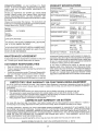
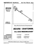
PRODUCT
CONGRATULATIONS
on your purchase of a Sears
Tractor. It has been designed, engineered and manufactured to give you the best possible dependability and
performance.
Should you experience any problem you cannot easily
remedy, please contact your nearesl Sears Authorized
Service Center/Department.
We have competent, we!ttrained technicians and the proper tools to service or repair
this tractor.
Please read and retain this manual. The instructions will
enable you to assemble and maintain your tractor properly.
Always observe the "SAFETY RULES".
MODEL
NUMBER
SPECiFiCATiONS
HORSEPOWER:
15.5
GASOLINE CAPACITY
AND TYPE:
1.25 GALLONS
UNLEADED REGULAR
O_L TYPE (API-SFiSG/SH):
SAE 30 (above 32°F)
SAE 5W-30 (below 32°F)
OiL CAPACITY:
3.0 PINTS
SPARK PLUG:
(GAP: .030")
CHAMPION
RJ19LM
VALVE CLEARANCE:
INTAKE:
EXHAUST:
_005" - .007"
.009" - .011"
GROUND SPEED (MPH):
FORWARD:
REVERSE:
TIRE PRESSURE:
FRONT:
REAR;
CHARGING SYSTEM:
3 AMPS BATTERY
5 AMPS HEADLIGHTS
BATTERY:
AMPiHR:
MtN. CCA:
CASE SIZE:
BLADE BOLT TORQUE:
30-35 FT. LBS.
,
917.258531
SERIAL
NUMBER
DATEOFPURCHASE
THE MODEL AND SERIAL NUMBERSWtLL
ON A PLATE UNDER THE SEAT.
BE FOUND
YOUSHOULD RECORDB©THSER{ALNUMBERAND
DATE OF PURCHASE AND KEEPIN A SAFE PLACE
FOR FUTURE REFERENCE.
MAINTENANCE
AGREEMENT
A Sears Maintenance
Agreement
uct. Contact your nearest Sears
CUSTOMER
,,,, ,,,,,,,,,
14 PSI
10 PSI
25
190
U1R
unimproved forest-covered, brush-covered or grass,covered land unless the engine's exhaust system is equipped
with a spark arrester meeting applicable Iocat or state laws
(if any). if a spark arrester is used, it should be maintained
in effective working order by the operator.
In the state of California the above is required by law
(Section 4442 of the California Public Resources Code).
Other states may have similar laws. Federallaws apply on
federal lands° A spark arrester for the muffler is available
through your nearest Sears Authorized Service Center/
Department (See REPAIR PARTS section of this manual).
is available on this prodstore for details.
RESPONSiBILiTIES
,
o
Read and observe the safety rules.
Follow a regular schedule in maintaining, caring for and
using your tractor.
,
Follow the instructions
under "Customer
Responsibilities" and "Storage"
sections of this owner's manual.
WARNING:
This tractor
is equipped
with an internal
combustion
engine and should not be used on or near any
LIMITED TWO YEAR WARRANTY
0 - 5.5
0-2.4
ON CRAFTSMAN
RIDING EQUIPMENT
For two (2) years from the date of purchase, if this Craftsman Riding Equipment is maintained, lubricated and tuned up according
to the instructions in the owner's manuat, Sears wifl repair or replace, free of charge, any parts found to be defective in material or
workmanship.
This Warranty does not cover:
•
_Expendable items which become worn during normal use, such as blades, spark plugs, air cleaners, betts, etc.
•
Tire replacement or repair caused by punctures from outside objects, such as nails, thorns, stumps, or glass.
•
Repairs necessary because of operator abuse, negligence, improper storage or accident or the failure to maintain the
,
equipment according to the instructions contained in the owner's manual.
,
Riding equipment used for commercial or rental purposes.
LIMITED 90 DAY WARRANTY
ON BATTERY
For ninety (90)days from date of purchase, if any battery included with this riding equipment proves defective in material or
workmanship and our testing determines the battery wil! not hold a charge, Sears will replace the battery at no charge.
IN-HOME WARRANTY SERVICE ON YOUR CRAFTSMAN RIDING EQUIPMENT iS AVAILABLE AT NO-CHARGE FOR 30
DAYS FROM THE DATE OF PURCHASE. PLEASE CONTACT YOUR NEAREST SERVICE CENTER. AFTER 30 DAYS FROM
THE DATE OF PURCHASE, WARRANTY SERVICE IS AVAILABLE BY TAKING YOUR CRAFTSMAN RIDING EQUIPMENT TO
YOUR NEAREST SEARS SERVICE CENTER. (IN-HOME WARRANTY SERVICE WiLL STILL BE AVAILABLE AFTER 30 DAYS
FROM THE DATE OF PURCHASE BUT A STANDARD TRIP CHARGE WILL APPLY.) THIS WARRANTY APPLIES ONLY
WHILE THIS PRODUCT IS IN THE UNITED STATES.
This Warranty gives you specific legal rights, and you may also have other rights which may vary from state to state.
SEARS, ROEBUCK AND CO., D/817 WA, HOFFMAN ESTATES, IL 6(]179
3
TABLE OF CONTENTS
OPERATION ...........................................................
10-15
MAINTENANCE SCHEDULE ......................................
16
SERVICE AND ADJUSTMENTS ............................ 21-26
STORAGE ....................................................................
27
TROUBLESHOOTING ............................................
28-29
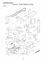
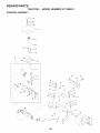
REPAIR PARTS - TRACTOR ................................. 32-49
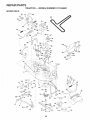
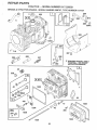
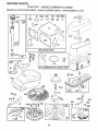
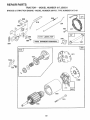
REPAIR PARTS - ENGINE .................................... 50-55
PARTS ORDERING/SERVmCE .................. BACK PAGE
SAFETY RULES ............................................................
2
PRODUCT SPECIFICAT|ONS ...................................... 3
CUSTOMER RESPONSiBiUTIES
..................... 3, 16-20
WARRANTY ..................................................................
3
TABLE OF CONTENTS ................................................
4
iNDEX ............................................................................
4
TRACTOR AGCESSOR}ES .......................................... 5
ASSEMBLY ................................................................
7-9
INDEX
A
Accessories ........................ ;................... 5
Adjustments:
Brake ...........................................
23
Carburetor ................................... 26
Mower:
Front_To-Back ........................ 22
Side*To-Side .......................... 22
Throttle Control Cabte ................. 25
Air Filter, Engine ................................. t9
Air Screen, Engine ............................. t9
Assembly ...........................................
7-9
B
Battery:
Charging .................................... 7-8
Cteaning ......................................
18
Connecting ................................. 7-8
Starting with Weak Battery ......... 24
Storage .......................................
27
Terminals ....................................
18
Belts:
Motion Drive
Removal/Replacement
.......... 23
Mower Blade Drive
Removal/Replacement
.......... 23
Blade:
Sharpening .................................
17
Replacement ...............................
17
Brake Adjustment ............................... 23
C
Carburetor Adjustment ....................... 26
Controls, Tractor ................................ t 1
Customer Responsibilities ............ t 6-20
Engine:
Air Filter ...................................
19
Air Screen, Engine .................. !9
Battery .....................................
18
Cooling Fins, Engine ............... 19
Engine Oil ...............................
18
Fuel Filter ................................ 20
Spark Plugs ............................ 20
Tractor:
Blades .....................................
!7
Lubrication Chart .................... 16
Maintenance Schedule ........... 16
Tire Care ......................... 8,17,24
Cutting Height, Mower ....................... t2
E
O
EleCtrical:
Oi!:
Interlocks and Relays ................ 25
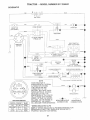
Schematic ................................... 3t
Wiring Diagram ........................... 32
Engine:
Air Filter: ......................................
t9
Air Screen ................................... t 9
Cooling Fins, Engine ................... !9
Oil Change .................................. t8
Oil Leve_ ................................. 13,18
Oil Type .......................................
18
Preparation ................................. 13
Repair Parts ........................... 50-55
Starting ........................................
t5
Storage .......................................
27
F
Filters:
Air ................................................
19
Fuel .............................................
20
Fuel:
Type ............................................
t4
Storage .......................................
27
Fuse ...................................................
25
G
Cold Weather Conditions ....... 14,18
Engine .........................................
18
Storage .......................................
27
Ope ration ......................................
10-15
Operating Mower ................................ 13
Options:
Accessories ...................................
5
Gauge Wheels ..................................... 8
H
Hood Removal/Installation ................. 25
L
Leveling Mower Deck .........................
Lubrication Chart ................................
M
Maintenance Schedule ......................
Mower:
Adjustment, Front-to-Back ..........
Adjustment, Side-to-Side ............
Blade Sharpening .......................
Blade Replacement ....................
Cutting Height .............................
Installation ...................................
22
16
16
22
22
17
17
12
21
Operation .................................... 14
Removai ...................................... 2!
Mowing Tips .......................................
15
Muffler ................................................
20
Spark Attester .......................... 3,42
Mulcher Plate .......................................
9
Spark Arrester ..........................
P
3,42
Parking Brake ...............................
11-t2
Pails Bag ..............................................
6
Paris, RepIacementiRepair
........... 32-.4.g
Product Specifications ........................... 3
R
Repair Parts ..................................
S
32-49
Safety Rules .........................................
Seat ......................................................
2
8
Service and Adjustments .............. 2!_26
Brake ...........................................
23
Carburetor ...................................
26
Fuse ............................................
25
Hood Removal/Installation .......... 25
Motion Drive Belt
Removal/Replacement
.......... 23
Mower Blade Drive Belt
Removal/Replacement
.......... 23
Mower Adjustment:
Front-to-Back ......................... 22
Side-to-Side ........................... 22
Mower lnstaIlation ....................... 21
Mower Removal .......................... 21
Tire Care ............................. 8,17,24
Slope Guide Sheet ............................. 59
Spar]< Plugs .......................................
20
Specifications .......................................
3
Starting the Engine ....................... 13-14
Steering Wheel ...............................
7,24
Stopping the Tractor. ......................... t2
Storage ...............................................
27
T
Throttle Control Cable Adjustment ..... 25
Tires ...........................................
8,17,24
Trouble Shooting Chart .................. 28-29
Transaxle Repair Parts .................
W
48-49
Warranty ...............................................
Wiring Diagram ..................................
Wiring Schematic ...............................
4
3
32
31
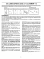
ACCESSORIES
AND ATTACHMENTS
These accessories and attachments were available through most Sears retail outlets and service centers when the tractor was purchased.
Most Sears stores can order these items for you when you provide the model number of your tractor.
ENGINE
SPARK PLUG
MAINTENANCE
GAS CAN
ENGINE OIL
i FUEL STABILIZER
AIR FILTER
BLADES
BELTS
PERFORMANCE
Sears offers a wide vadety of attachments that fit your tractor.
you. This list was current at the time Of publication; however,
may be made in these attachments, or some may no longer
accessories and attachments
that are available for your
Most of those attachments do not require additional hltches
attaching and detaching.
Many of those are listed below with brief explanations of how they can help
it may change in future years - more attachments may be added, changes
be available or fit your model. Contact your nearest Sears store for the
tractor.
or conversion kits (those that do are indicated) and are designed for easy
AERATOR promotes deep root growth for a healthy lawn. Tapered 2.5-inch steel spikes mounted on 10-inch diameter discs
puncture holes in soif at close intervals to let moisture soak in.
Steel weight tray for increased penetration.
BAGGER !ets you collect
grass clippings and leaves for a
hea{thier, nearer looking lawn. Two Permanex containers hold
30-gallon plastic bags.
BUMPER protects front end of tractor from damage.
CARTS make haufing easy= Variety of sizes available, plus
accessories such aS side panel kits, tool caddy, cart cover,
protective mat and dolly.
CORING AERATOR takes small plugs out of soil to allow moisture and nutrients to reach grass roots. 36-inch swath. 24
hardened steel coring tips. 150 lb. capacity weight tray.
EASY OIL DRAIN VALVE makes oil changes easier, faster.
FRONT NOSE ROLLER canters in front of mower deck to reduce
chances of "scal_ing" on uneven terrain.
GANG HITCH lets you tow 2 or 3 pt_tt-behind attachments at once,
such as sweepers; dethatchers, aerators (not for use with to{lets,
carts or other heavy attachments).
GAUGE WHEELS on both sides of the mower deck reduce
chances of "scalping" on uneven terrain. For mower decks not so
equipped.
MULCH RAKF_./DETHATCHER loosens solt and flips thatch and
matted Ieaves to lawn surface for easy pickup. Twenty spring tine
teeth. Usefulto prepare bare areas for seeding. Available for front
or rear mounting.
HiGH PERFORMANCE
REEL-ACTiON
SPRING'TtNE
DETHATCHER
covers 36-inch wide path and
tosses thatch into large hopper. Mounts behind tractor.
MULCHING CLOSE-OUT PLATE KiT, once installed_ !ets you
mulch, discharge or bag clippings (bagger optional) without
changing blades. For models not equipped as 3-in-1 Converfible
mowers. See "MOWER" in the Repair Parts section of this
manual,
RAMP TOPS AND FEET let you load and unload tractor from a
pickup truck. Use with 2 x 8 or 2 x 10 lumber.
ROLLER for smoother lawn surface,
36-inch wide, 18-inch
diameter water-tight drum holds up to 390 lbs. of weight. Rounded
edges prevent harm to turf. Adjustable scraper automatically
cleans drum.
SNOW BLADE for snow removal only. 14-inch high, 48-inch wide
blade dears 42-inch path when angled left or right. Raises, lowers
with side lever. Adjustable skids; replaceable, reversible scraper
bar, (Use with tire chains and wheel weights and/or rear drawbar
weight.)
SNOWTHROWER has 40-inch swath. Drum4ype auger handles
powdery and wet/heavy snow. Mounts easily with simple pin
arrangement. Discharge chute adjusts from tractor seat. 6-inch
diameter spout discharges snow ! 0 to 50 feet. Lift controlled at
tractor seat. (Use with chains and wheel weights and/or rear
drawbar weight.)
SPRAYERS use 12-volt DC electric motor that connects to the
tractor battery or other 12-volt source,
includes booms for
automatic spraying and hand held wand for spot spraying. Wand
has adjustable spray pattern. For applying herbicides, insecticides, fungicides and ti_quidfertilizers.
SPREADER/SEEDERS
make seeding, fertilizing, and weed killing easy. Broadcast spreaders are also useful for granular deicers and sand.
SWEEPERS let you collect grass clippings and leaves.
TILLER has 5 hp engine and 36-inch swath to prepare seed beds,
cultivate and compost garden residue. Tiiler has its own built-in
lift and depth cont rol system and does NOT require a sleeve hitch.
Fits any lawn, yard or garden tractor. Simp{y hook up to the tractor
drawbar and go! Optional
accessories
convert unit for
dethatching, aerating, hiliing...without tools.
TIRE CHAINS are heavy duty; closely spaced extra-large cross
links give smooth ride, outstanding traction.
TRACTOR CAB has heavy duty vinyl fabric over tubular steel
frame, ABS ptastic top; clear plastic windshield offers 360 degree
visibility. Hinged metal doors with catch. Keeps operator warm
and dry. Remove vinyl sides and windshields for use as sun
protector in summer. Optional accessories
include:
tinted/
tempered solid safety glass windshield with hand operated wiper;
12-vott amber caution light for mounting on cab top.
VACS for powerful collection of heavy grass clippings and leaves.
Optional wand attachment to pick up debris in hard-to-reach
places+ VAC/CHiPPER includes a chipper-shredder.
WEIGHT BRACKET for drawbar for snow removal applications.
Uses (t) 55 lb. weight.
WHEEL WEIGHTS for rear wheels provide needed traction for
snow removal or dozing heaw materials.
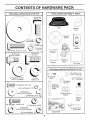
CO
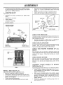
NTS OF HA
Parts Bag contents
E PACK
Parts packed
shown full size
separately
in carton
Seat
Mulcher
Plate
Steering
Wheel
(1) Lock
(1) Hex Bolt 5/16-t8
video
(1) Locknut
washer
3/8
5/!6-18
x I-1/4
_
_
Cassette
(1) Hex Bof
1/2-13 x 1
1
Manual
Steering
Boot
Parts bag contents
'
......
Parts Bag
not shown
full size
(2) Washers 3/8
x 7/8 x 14 Gauge
(1) Washer 17/32 x
1-3/16 x 12 Gauge
(2) Shoulder
Bolts
(1) Lock
Washer 1/2
_
=
(2) Washers
|
i
3/16 x 3!4 x16 Gauge
_
(2) Weld Nuts #10
Q(2)
Centerlock Nuts
Gauge
Wheels
Steering
Extension
Shaft
C
(2) Keys
i
o
1
Steering Wheel
Adapter
Steering
Wheel
Insert
(2) Hex Bolts 1/4-20 x 3/4
(2) Hex Nuts 1/4_20
9/32 x 5/8 x 16 Gauge
(2) Washers
(2) Lock Washers
(2) Latch Hook
Assemblys
Slope Sheet
1/4
!6
ASSE
,_ ................
_iv.
,.L.......................
Your new tractor has been assembled at the factory with exception of those parts left unassembled for shipping purposes.
To ensure safe and proper operation of your tractor all parts and: hardware you assemble must be tightened securely, Use
the correct tools as necessary to insure proper tightness.
TOOLS REQUIRED
FOR ASSEMBLY
A socket wrench set will make assembly easier. Standard
wrench sizes are listed.
(2) 7/16" wrenches
Phitlips Screwdriver
(1) 1/2" wrench
Tire pressure gauge
(1) 9/16" wrench
Utitity knife
(1) 3/4" Socket w/drive rachet
When right or left hand is mentioned in this manuat, it
means when you are in the operating position (seated
behind the steering wheel).
WHEEL
............
J....
STEERING
BOOT
TO REMOVE TRACTOR FROM CARTON
UNPACK
•
CARTON
Remove all accessible loose parts and parts cartons
from carton (See page 6);
Cut, from top to bottom, along lines on all four corners
of carton, and lay panets flat,
Check for any additional loose parts or cartons and
remove.
ADAPTER
--_
EXTENSION
SHAFT
5/16 HEX BOLT
5116 LOCKNUT
BEFORE ROLLING TRACTOR OFF SKID
ATTACH
STEERING
WHEEL
(See Fig. I)
ASSEMBLE EXTENSION SHAFT AND BOOT
LOWER
STEERING
SHAFT
,
Slide extension shaft onto lower steering shaft. Align
mounting holes in extension and lower shafts and
install 5/16 hex bolt and locknut. Tighten securely.
IMPORTANT: TIGHTEN BOLT AND NUT SECURELY TO
18-22 FT. LBS TORQUE.
INSTALL STEERING WHEEL
Position front wheels of the tractor so they are pointing
straight forward.
o
Slide steering wheei adapter onto steering shaft extension;
o
Position steering wheel and sleeve assembly so cross
bars are horizontal (ieftto right) and slide onto adapter.
Assemble large flat washer, 3/8 lock washer, 3/8 hex
bolt and tighten securely.
=
=
-
Roll tractor backwards off skid.
•
Remove banding holding discharge guard up against
tractor.
NOW TO SET UP YOUR TRACOTR
CONNECT
........
Release parking brake by depressing
pedal.
o
Place freewheel control in freewheeling position to
disengage transmission (See "TO TRANSPORT" in
the Operation Section of this manual).
2 and 3)
=L=
=_
Remove cardboard packing from seat pan and lift seat
pan to raised position.
TO RO LL TRACTOR OFF SK|D (See Operation
section for location and function
of controls)
,
(See Figs.
Positive terminal must be connected
first to prevent sparking from accidental grounding.
,
Remove protective plastic from tractor hood and grill
IMPORTANT: CHECK FOR AND REMOVE ANY STAPLES
IN SKID THAT MAY PUNCTURE TIRES WHERE TRACTOR
IS TO ROLL OFF SKID.
Press lift lever plunger and raise attachment lift lever to
its highest position.
BATTERY
CAUTION: Do not short battery terminals. Before connecting battery, remove metal bracelets,
wristwatch
bands, rings, etc.
Snap steering wheel insert into center of steering
wheel.
,
"-
_'
l
_ _ _ .'_
FIG. 1
Place tabs of steering boot over tab slots in dash and
push down to secure.
*
I
_ .
_
•
Open battery box door.
Remove terminal protective caps and discard.
If this battery is put into service after month and year
indicated on label (label located between terminals)
charge battery for minimum of one hour at 6-10 amps.
clutch/brake
,
7
First connect RED battery cabte to positive (+) terminal
with hex bolt, flat washer, lock washer and hex nut as
shown, Tighten securely.
ASSEMBLY
=
Connect BLACK grounding cable to negative (-) terminal with remaining hex bolt, fiat washer, lock washer
and hex nut. Tighten securely,
,
,
Close battery box door.
•
•
Open battery box door for:
Inspection for secure connections
ware).
•
Inspection for corrosion.
•
Testing battery,
•
Jumping (if required).
Slide seat until a comfortable position is reached which
allows you to press clutch/brake pedal all the way
down.
Get off seat without moving its adjusted position,
Raise seat and tighten adjustment bolt securely.
(to tighten hard-
SEAT
SEAT PAN
SHOULDER
Periodic charging.
BOLT _
DISCARD TERMINAL
PROTECTIVE CAPS
LARGE
\
ADJUSTMENT
BOLT
FLAT WASHER
"LOCK WASHER
FiG. 4
HEX
NUT
HEX
BOLT
CHECK T_RE PRESSURE
The tires on your tractor were ovefinflated
shipping purposes. Correct tire pressure
best cutting performance.
•
Reduce tire pressure to PSI shown
SPECIFICATIONS" on page 3 of this
CHECK DECK
I
POSITIVE
(RED) CABLE
NEGATWE
(BLACK} CABLE
F_G, 2
in "PRODUCT
manual.
LEVELNESS
For best cutting results, mower housing should be properly
leveled. See "TO LEVEL MOWER HOUSING" in the
Service and Adjustments section of this manual.
CHECK
BELTS
FOR
PROPER
POSITION
OF
ALL
See the figures that are shown for replacing motion and
mower blade drive belts in the Service and Adjustments
section of this manual, Verify that the belts are routed
correctly.
SEAT
PAN
CHECK BRAKE
BATTE
BOX DOOR
SYSTEM
After you learn how to operate your tractor, check to see
that the brake is properly adjusted. See "TO ADJUST
BRAKE" in the Service and Adjustments section of this
manual.
ASSEMBLE
GAUGE
DECK (See Fig. 5)
FiG. 3
INSTALL
at the factory for
is important for
TO
MOWER
Assemble gauge wheels with tractor on a flat level surface.
,
Adjust mower to desired cutting height (See "TO ADJUST MOWER CUTRNG HEIGHT" in the Operation
section of this manual).
*
With mower in desired height of cut position, gauge
wheels should be assembled so they are slightly off the
ground. Install gauge wheel in appropriate hole with
shoulder bolt, 3/8" washer and 3/8-16 Iocknut and
tighten securely.
SEAT (See Fig, 4)
Adjust seat before tightening adjustment bolt.
•
Remove cardboard packing on seat pan.
,
Place seat on seat pan and assemble shoulder bolt.
•
Assemble adjustment bolt, lock washer and flat washer
loosely. Do not tighten.
,
Tighten shoulder bolt securely.
•
Lower seat into operating position and sit on seat.
WHEELS
Repeat for opposite side installing
same adjustment hole.
gauge wheel in
°_
i?i
BLY
TO CONVERT
DiSCHARGiNG
GAUGE WHEEL
MOUNTING
BRACKET
TO BAGGING
OR
Simply remove mulcher plate and store in a safe place,
Your mower is now ready for discharging or installation of
optional grass catcher accessory.
DEFLECTOR
3/8-16
LOCKNUT
SHOULDER
BOLT
318" WASHER
GAUGE WHEEL"
FIG. 5
LATCH
HOOKS
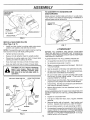
iNSTALL
(See
MULCHER
Figs.
PLATE
6 & 7)
Install two latch hooks to mutcher plate using screw,
washer, lock washer, and weld nut as shown.
NOTE: Pro-assemble weld nut to latch hook by inserting
weld nut from the top with hook pointing down.
FiG° 7
,
=
Tighten hardware securely.
•
Raise and hold deflector shield in upright position.
•
Place front of mutcher plate over front of mower deck
opening and slide into place, as shown.
Hook front latch into hole on front of mower deck.
•
Hook rear latch into hole on back of mower deck.
CAUTION: Do not remove discharge
guard from mower. Raise and hold
guard when attaching mulcher plate
and allow it to rest on plate while in
operation.
WELD NUT FROM THE TOP
WELD
NUT X
HOOK POINTS DOWN
LOCK
WASHER
SCREW
BEFORE YOU OPERATE AND ENJOY YOUR NEW
TRACTOR, WE WISH TO ASSURE THAT YOU RECEIVE
THE BEST PERFORMANCEAND SATISFACTION FROM
THIS QUALITY PRODUCT.
PLEASE REVIEW THE FOLLOWING CHECKLIST:
,/
All assembly instructions have been completed.
,/
No remaining loose parts in carton.
¢
Battery is properly prepared and charged.
1 hour at 6 amps).
¢
Seat is adjusted comfortably and tightened securely.
/
All tires are properly inflated. (For shipping purposes,
the tires were overinfiated at the factory).
(Minimum
¢
Be sure mower deck is properly leveled side-to-side/
front-to-rear for best cutting results. (Tires must be
properly inflated for leveling).
_" Checkmower and drive belts. Be sure they are routed
properly around pulleys and inside all belt keepers.
v"
Check wiring. See that all connections
and wires are properly clamped.
are still secure
,/
Before driving tractor, be sure freewheel control is in
drive position.
WHILE LEARNING HOW TO USE YOUR TRACTOR, PAY
EXTRA ATTENTION TO THE FOLLOWING IMPORTANT
ITEMS:
LATCH
LATCH
HOOK
LOCK
WASHER
,/"CHECKLIST
I WASHER
WASHER
MULCHER
PLATE
FIG, 6
WELD
NUT
¢"
Engine oil is at proper level.
¢"
Fuel tank is filled with fresh, clean, regular unleaded
gasoline.
Become familiar with all controls - their location and
function. Operate them before you start the engine.
,/
,/
Be sure brake system is in safe operating condition.
¢"
It is important to purge the transmission before operating your tractor for the first time: Fo!low proper starting
and transmission purging instructions (See"TO START
ENGINE" and "PURGE TRANSMISSION" in the Operation section of this manual).
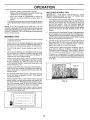
OPERATION
These symbols
may appear
on your tractor or in literature
supp!ied with the product.
,il
Learn and understand
their meaning.
t
BATTERY
CAUTION OR
WARNING
REVERSE
FORWARD
FAST
SLOW
ENGINE ON
ENGINE OFF
OIL PRESSURE
CLUTCH
LIGHTS ON
LIGHTS OFF
DIFFERENTIAL
LOCK
PARKING BRAKE
LOCKED
UNLOCKED
- IIT
FUEL
CHOKE
REVERSE
MOWER LIFT
MOWER HEIGHT
NEUTRAL
ATTACHMENT
CLUTCH ENGAGED
HIGH
LOW
PARKING BRAKE
IGNITION
ATTACHMENT
CLUTCH DISENGAGED
HYDROSTATIC
DANGER, KEEP HANDS AND FEET AWAY
FREE WHEEL
(Hydro Modets only)
10
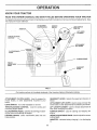
OPERATION
KNOW YOUR TRACTOR
READ,THIS
OWNER'S
MANUAL
Comparetheiilustrationswithyourtractor
this manUal for future reference,
AND SAFETY
RULES
BEFORE
tofamiiiarizeyoursetfwiththe{ocations
ATTACHMENT
CLUTCH LEVER
OPERATING
YOUR
TRACTOR
of various controls and adjustments. Save
IGNITION
SWITCH
LIGHT SWITCH
POSITION
LiFT LEVER
PLUNGER
r
ATTACHMENT
LIFT LEVER
CLUTCH/BRAKE
PEDAL
PARKING
BRAKE
HEIGHT
ADJUSTMENT
KNOB
GEARSHIFT
LEVER
FIG. 8
•
Our tractors conform to the safety standards of the American National Standards institute,
GEARSHIFT LEVER: Selects the speed and direction of
tractor.
ATTACHMENT CLUTCH LEVER: Used to engage the
mower blades, or other attachments mounted to your
tractor.
LIGHT SWITCH:
ATTACHMENT LIFT LEVER: Used to raise and lower the
mower deck or other attachments mounted to your tractor,
Turns the headlights on and off.
THROTTLE]CHOKE
CONTROL:
controlling engine speed.
LiFT LEVER PLUNGER: Used to release attachment lift
lever when changing its position.
Used for starting and
CLUTCH/BRAKE PEDAL: Used for declutching and braking the tractor and starting the engine.
IGNITION SWITCH:
engine.
PARKING BRAKE:
brake position.
HEIGHT ADJUSTMENT
cutting height,
Locks clutch/brake
pedal into
the
AMMETER:
(4.
11
•
Used for starting and stopping the
KNOB" Used to adjust the mower
Indicates battery charging (+) or discharging
OPERATION
over the spectacles
or standard
safety gmasses.
HOW TO USE YOUR TRACTOR
TO SET PARKING
BRAKE
o Never use choke to stop engine.
NOTE: Under certain conditions when tractor is standing
idle with the engine running, hot engine exhaust gases may
cause "browning" of grass. To eliminate this possibility,
always stop engine when stopping tractor on grass areas.
(See Fig. 9)
Your tractor is equipped with an operator presence sensing
switch. When engine is running, any attempt by the
operator to leave the seat without first setting the parking
brake will shut off the engine.
,
Depress clutch/brake
and hold,
A
pedal into full "BRAKE" position
Place parking brake Iever in "ENGAGED" position and
release pressure from clutch/brake pedal. Pedal should
remain in "BRAKE" position. Make sure parking brake
will hold tractor secure,
TO USE THROTTLE
CONTROL
(See Fig. 9)
Always operate engine at full throttle,
,
ATTACHMENTCLUTCHLEVER
"ENGAGED"POSITION
THROTTLE/
CHOKE
CONTROL
pletely, as described above, before leavCAUTION:
A_ways position;
stop tractor
coming
the operator's
to empty
grass catcher, etc.
Operating engine at less than full throttle reduces the
battery Charging rate.
Futl throttle offers the best bagging and mower performance.
TO MOVE FORWARD
Fig. 9)
AND BACKWARD
(See
The direction and speed of movement is controlled by the
motion control lever.
GEARSHIFT
LEVER
•
Start tractor with motion control tever in neutral (N)
position.
,
Release parking brake and clutch/brake
=
Slowly move motion control fever to desired position.
pedal
"D|SENGAGED"
POSI]_ON
CLUTCH/BRAKE
PEDAL
"DRIVE" POSITION
HE|GHT ADJUSTMENT
TO ADJUST MOWER
(See Fig. 9)
KNOB
FIG. 9
STOPPING
(See Fig. 9)
Turn knob clockwise (f_)
Move attachment clutch lever to "DISENGAGED"
sition,
(_)
to lower cutting
The cutting height range is approximately 1-I/2" to 4". The
heights are measured from the ground to the blade tip with
the engine not running, These heights are approximate
and may vary depending upon soif conditions, height of
grass and types of grass being mowed.
Depress clutch/brake pedal into tuli "BRAKE" position,
Move motion control lever to neutral (N) position,
IMPORTANT:
THE MOTION CONTROL LEVER DOES
NOT RETURN TO NEUTRAL (N) POSITION WHEN THE
CLUTCH/BRAKE
PEDAL IS DEPRESSED,
,
ENGINE Move throttle control to slow (,_)
to raise cutting height.
Turn knob counterclockwise
height.
po-
GROUND DRIVE -
•
HEIGHT
The cutting height is controlled by turning the height adjustment knob in desired direction.
MOWER BLADES•
CUTTING
position.
The average lawn should be cutto approximately 2-I/2
inches during the cool season and to over 3 inches
during hot months. For healthier and better looking
lawns, mow often and after moderate growth.
For best cutting performance, grass over 6 inches in
height should be mowed twice. Make the first cut
relatively high; the second to desired height.
NOTE: Failure to move throttle control to slow (,_)
position and allowing engine to idle before stopping may
cause engine to "backfire".
Turn ignition key to "OFF" position and remove key.
Always remove key when ieaving tractor to prevent
unauthorized use.
!2
•
::;7i!¸:I: !iir_!_i7:
7!: ,
OPE
AT!ON
t
TO OPERATE
IMPORTANT:
THE MOTION CONTROL LEVER DoEs
NOT RETURN TO NEUTRAL (N) POSITION WHEN THE
CLUTCH/BRAKE PEDAL tS DEPRESSED•
,MOWER (See Fig. 10}
Your tractor is equipped With an operator presence sensing switch. Any attempt by the operator to leave the seat
with the engine running and the attachment clutch engaged
will shut off the engine.
,
,
Select desired height of cut.
Lower mower with attachment lift control.
,
Start mower blades by engaging attachment
control.
.
TO STOP MOWER BLADES - disengage attachment
clutch control;:
i
_A
I t_l_
ATTACHMENT CLUTCH £EVER
"DISENGAGED"
POSITION
,,
\
"ENGAGED"
POSITION
Y
_ _--_._
/
i
/ ,
To restart movement, slowly release parking brake and
clutch/brake pedal;
*
Slowly move motion control lever to slowest setting.
-
Make all turns slowly.
clutch
TO TRANSPORT
(See Figs. 8 and 11)
When pushing or towing your tractor, be sure to disengage
transmission by placing freewheel control in freewheeling
position: Free wheel control is located at the rear drawbar
of tractor.
w_regrasseatcher,
_pad,
charge
charge guard
guard in place,
place.
,
or the ills................-_
o
Raise attachment lift to highest position with attachmerit lift control.
-
Pull freewheel control knob out and hold in position by
inserting retainer sp ring into forward hole of control rod.
,
Do not push or tow tractor at more than two (2) MPH.
To reengage transmission, reverse above procedure.
ATTACHMENT
LiFT LEVER
NOTE: To protect hood from damage when transporting
your tractor on a truck or a trailer, be sure hood is closed
and secured to tractor. Use an appropriate means of tying
hood to tractor (rope, cord, etc.).
,, ;::--__._
i
i
FIG. 11
DISCHARGE
GUARD
FIG. 10
TO OPERATE
!
_
BEFORE STARTING
ON HILLS
CHECK
CAUTION:
Do not drive up or down
hills with:slopes greater than !5 ° and
•
ChQose the slowest speed before starting up or down
hills.
•
Avo!d stopping or changing speed on hills.
•
If slowing iS necessary, move throttle control lever to
sl0wer P6sitiom
If stopping is absolutely necessary, push clutch/brake
pedal quickly to brake position and engage parking
brake_
,
Move motion control lever to neutral (N) position.
13
ENGINE
TIlE ENGINE
OIL LEVEL (See Fig. 17)
•
The engine in your tractor has been shipped, from the
factory, already filled with summer weight oil.
•
Check engine oil with tractor on level ground.
,
Remove oil fill cap/dipstick and wipe clean, relnsert the
dipstick and screw cap tight, wait for a few seconds,
remove and read oil level. If necessary, add oil until
"FULL" mark on dipstick is reached. Do not overfill.
For cold weather operation you should change oil for
easier start ng (See l_OIL VISCOSITY CHART _ • n t h e
Customer Responsibilities section of this manual).
•
To change engine oil, see the Customer Responsibilities section in this manual,
OPERATION
ADD GASOMNE
o
Fill fuel tank. Use fresh, clean, regular unleaded
gasoline with a minimum of 87 octane. (Use of leaded
gasoline will increase carbon and lead oxide deposits
and reduce valve life). Do not mix oil with gasoline.
Purchase fuel in quantities that can be used within 30
days to assure fuel freshness.
IMPORTANT: WHEN OPERATING IN TEMPERATURES
BELOW 32°F(0°C), USE FRESH, CLEAN WINTER GRADE
GASOLINE TO HELP INSURE GOOD COLD WEATHER
STARTING.
WARNING:
Experience indicates that alcohol blended
fuels (called gasohol or using ethanol or methanol) can
attract moisture which leads to separation and formation of
acids during storage. Acidic gas can damage the fuel
system of an engine while in storage. To avoid engine
problems, the fuel system should be emptied before storage of 30 days or longer. Drain the gas tank, start the
engine and let it run until the fuel lines and carburetor are
empty. Use fresh fuel next season. See Storage Instructions for additional information.
Never use engine or
carburetor cleaner products in the fue! tank or permanent
damage may occur.
•
Move motion control lever to neutral (N) position:-Shutoff engine and set parking brake.
,
Engage transmission by placing freewheel control in
driving position (See "TO TRANSPORT" in this section
of manual)_
•
Sitting inthetractor seat, start engine. Aftertheengine
is running, move throttle control to half (1/2) speed.
With motion control lever in neutral (N) position, slowly
disengage clutch/brake pedal.
,
Slowly move motion control lever forward, after the
tractor moves approximately five (5) feet, slowly move
motion control lever to reverse position.
After the
tractor moves approximately five (5) feet return the
motion control lever to the neutral (N) position. Repeat
this procedure with the motion control lever three (3)
times.
Your tractor is now purged and now ready for normal
operation.
TO START
ENGINE
(See Fig. 9}
When starting the engine for the first time or-if the engine
has run out of fuel, it will take extra, cranking time to move
fuel from the tank to the engine.
,
Be sure freewheel control is in the transmission engaged position.
Sit on seat in operating position, depress clutch/brake
pedal and set parking brake.
,
Place motion control lever in neutral (N) position.
PURGE TRANSMISSION
Move attachment clutch to "DISENGAGED"
o
position.
Move throttle control to choke (l\l) position
.Note: Before starting; read the warm and cold starting
procedures below.
•
To ensure proper operation and performance, it is recommended that the transmission be purged before operating
tractor for the first time. This procedure will remove any
trapped air inside the transmission which may have developed during shipping of your tractor.
IMPORTANT: SHOULD YOUR TRANSMISSION REQUI RE
REMOVAL FOR SERVICE OR REPLACEMENT,
IT
SHOULD BE PURGED AFTER REINSTALLATION
BEFORE OPERATING THE TRACTOR.
o
Place tractor safely on level surface with engine off and
parking brake set.
•
Disengage transmission by placing freewheel control
in freewheeling position (See "TO TRANSPORT" in
this section of manual).
•
Sitting in the tractor seat, start engine. After the engine
is running, move throttle controi to slow (,4_) position.
With motion control lever in neutral (N) position, slowly
disengage clutch/brake pedal,
•
lnsertkeyintoignitionandturnkeyclockwiseto"START"
position and release key as soon as engine starts. Do
not run starter continuously for more than fifteen seconds per minute, tf the engine does not start after
several attempts, move throttle control to fast (,_)
position wait a few minutes and try again. If engine still
does not start, move the throttle contro back to the
choke (N) position and retry.
WARM WEATHER STARTING (50 ° F and above)
-
When engine starts, move the throttle control to the fast
(,f_) position.
The attachments and ground drive can now be used. If
the engine does not accept the toad, restart the engine
and allow it to warm up for one minute using the choke
as described above.
COLD WEATHER STARTING ( 50° F and below)
When engine starts, allow engine to run with the throttle
control in the choke (l\i) position until the engine runs
roughly, then move throttle control to fast 0 position.
This may require an engine warm-up period from
several seconds to several minutes, depending on the
temperature.
Move motion control lever to full forward position and
hold for five (5) seconds. Move lever to full reverse
position and hold for five (5) seconds. Repeat this
procedure three (3) times.
HYDROSTATIC
NOTE: During this procedure there will be no movement of
drive wheels. The air is being removed from hydraulic drive
system.
•
14
TRANSMISSION
WARM UP
Before driving the unit in cold weather, the transmission should be warmed up as follows:
OPERATION
.............
_
__=-.=
-
•
Place the motion control lever in neutral.
Release the parking brake and let the clutch!brake
s]owty return to operating position.
Allow one minute for transmission to warm uo.
This can be done during the engine warm up
period.
Theattachments
can also be used during the engine
warm_up oeriod after the transmission has been warmed
up.
MULCHmNG MOWING
mMPORTANT:
FOR BEST PERFORMANCE,
KEEP
MOWER HOUSING FREE OF BUILT-UP GRASS AND
TRASH. CLEAN AFTER EACH USE,
NOTE: If at a high altitude (above 3000 feet) or in cold
temperatures (below 32 F) the carburetor fuel mixture may
need to be adjusted for best engine performance. See "TO
ADJUST CARBURETOR" in the Service and Adjustments
section of this manual.
MOWING
=
•
The special mulching blade will recut the grass clippings many times and reduce them in size so that as
they fall onto the lawn they will disperse into the grass
and not be noticed. Also, the mulched grass wilt
biodegrade quickly to provide nutrients for the lawn.
Always mulch with your highest engine (blade) speed
as this will provide the best recutting action of the
blades.
•
Avoid cutting your tawn when it is wet. Wet grass tends
to form clumps and interferes with the mulching action.
The best time to mow your lawn is the early afternoon.
At this time the grass has dried and the newly cut area
will not be exposed to the direct sun.
•
For best results, adjust the mower cutting height so that
the mower cuts off only the top one,third of the grass
blades (See Fig. 13). For extremely heavy mulching,
reduce your width of cut and mow slowly.
=
Certain types of grass and grass conditions may require that an area be mulched a second time to
completely hide the clippings. When doing a second
cut, mow across or perpendicular to the first cut path.
-
Change your cutting pattern from week to week. Mow
north to south one week then change to east to west the
next week. This will help prevent matting and graining
of the lawn.
TKPS
Tire chains cannot be used when the mower housing
is attached to tractor.
o
TIPS
Mower should be properly leveled for best mowing
performance. See"TQ LEVEL MOWER HOUSING" in
the Service and Adjustments section of this manual.
The left hand side of mower should be used for trimming.
Drive so that clippings are discharged onto the area
that has been cut. Have the cut area to the right of the
tractor. This will result in a more even distribution of
clippings and more uniform cutting.
When mowing large areas, start by turning to the right
so that clippings will discharge away from shrubs,
fences, driveways, etc. After one or two rounds, mow
in the opposite direction making Ieft hand turns until
finished (See Fig. 12 ).
MAX 1./3
If grass is extremely tall, it should be mowed twice to
reduce load and possible fire hazard from dried clippings. Make first cut relatively high; the second to the
desired height.
Do not mow grass when it is wet. Wet grass will plug
mower and leave undesirable clumps, Allow grass to
dry before mowing,
Always operate engine at full throttle when mowing to
assure better mowing performance and proper discharge of material. Regulate ground speed by selecting a low enough gear to give the mower cutting
performance as well as the quality of cut desired.
•
FIG. 13
When Operating attachments, select a ground speed
that wilt suit the terrain and give best performance of
the attachment being used.
f
FIG. 12
15
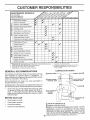
CUSTOM
MAINTENANCE
RESPONSIBILITIES
SCHEDULE
FILL tN DATES
AS YOU COMPLETE
REGULAR SERVICE
_ERVICE DATES
Check
Brake Operation
Chec
Tire Pressure
_
T I C
for Loose Fasteners
a
,,n/Replace Mower
f
_/7
_tionChart
T l
Battery Level/Recharge
....
__
t Clean Battery and Terminals
R I Check
Transaxle
Cooling
Adjust
Blade Belt(s) Tension
Adjust
Motion Drive Belt(s) Tension
Check Engine Oi[ Level
_##
a Engine Oil
Nt
|
Clean
I InsF
t Muffler/Spark
_2
,
L_2
L.
F
..........
Arrester
Oil Filter (If equipped)
N t Clean Engine
E I Re1
_2,3
__
f_ir Screen
I Replace
_#'
_
E 1 Clean Air Filter
G
!J
Biades
At
C l
0
!# #
_,2
Cooting Fins
_f2
,e Spark Plug
_
,oAirF lferPaporCa , dge
1 1 I
IJ2
-R-eeplace Fuel Filter
12 3 4-
Change more often when operating under a heavy _oad or in high ambient temperatures.
Service mere often when operating in dirty o[ dusty conditions,
if equipped with oil filter, change oil every 50 hours.
Replace blades more often wl_en mowing in sandy soil,
GENERAL
5 _ tf equipped with adiustabte system.
6 * Not required if equipped with maintenance*free battery,
7 - Tighten front axle pivot belt to 35 fLqbs, max4mum.
Do not overtighten,
LUBRICATION
RECOMMENDAT|ONS
G
The warranty on this tractor does not cover items that have
been subjected to operator abuse or negligence.
To
receive full value from the warranty, operator must maintain
tractor as instructed in this manual.
NDLE ZERK (_)
(_ FRONT
BEARING
Some adjustments will need to be made periodically to
properly maintain your tractor.
ZERK
Atl adjustments in the Service and Adjustments section of
this manual should be checked at least once each season.
•
EACH
C)ATTAC
CLUTCH
PIVOT(S)
USE
,
Check engine oil level.
o
Check brake operation.
•
•
Checktire pressure.
Check for loose fasteners.
FRONT WHEEL
BEARING ZERK
9
Once a year you should replace the spark plug, clean
or replace air filter, and check blades and belts for
wear. A new spark plug and clean air filter assure "
proper air-fuel mixture and help your engine run better
and last longer.
BEFORE
CHART
,_EARSHIFT (_
PIVOTS
SAE 30 OR !0W30 MOTOR OIL
(_) GENERAL
16
PURPOSE GREASE
(_) REFER TO CUSTOMER RESPONS_BiLiTIES
"ENGINE" SECTION
IMPORTANT:
DO NOT OiL OR GREASE THE PIVOT POINTS
WHICH HAVE SPECIAL NYLON BEARINGS,
VISCOUS
LUBRICANTS WILL ATTRACT
DUST AND DIRT THAT WILL SHORTEN
THE LIFE OF THE SELF*LUBRICATiNG
BEARINGS,
tF YOU
FEEL THEY MUST BE LUBRICATED,
USE ONLY A DRY, POWDERED GRAPHITE
TYPE LUBRICANT
SPARINGLY,
.........................
CUSTOMER
RESPONSIBILITIES
TRACTOR
o.,o, c
Always observe safety rules when performing any maintenance.
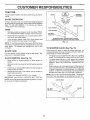
BRAKE
OPERATION
ff tractor requires more than six (6) feet stopping distance
at high speed in highest gear, then brake must be adjusted.
(See "TO ADJUST BRAKE" in the Service and Adjustments section of this manuat)i
GE
FLAT WASHER
TIRES
,,
Maintain proper air pressure in all tires (See "PRODUCT SPECIFICATIONS,' on page 3 of this manual).
•
Keep tires free of gasoline, oil, or insect control chemicals which can harm rubber.
,
Avoid stumps, stones, deep ruts, sharp objects and
other hazards that may cause tire damage.
TO SHARPEN
REMOVAL
(See Fig. 14)
Raise mower to highest position to allow access to
blades.
e
Remove hex bolt. lock washer and flat washer securing
blaae.
o
Install new or resharpened blade with trailing edge up
towards deck as shown.
e
Reassemble hex bolt. ocK washer and flat washer ir
exact order as shown.
BLADE
(See Fig. 15)
Care should be taken to keep the blade balanced. An
unbalanced blade will cause excessive vibration and eventual damage to mower and engine.
For best results mower blades must be kept sharp. Replace bent or damaged blades.
BLADE
_'_-""'_.z
FIG. 14
CARE
,
GE
*A GRADE 8 HEAT TREATED BOLT CAN BE
IDENTIFIED BY SIX LINES ON THE BOLT HEAD.
NOTE: To seal tire punctures and prevent flat tires due to
slow leaks, tire sealant may be purchased from your local
parts dealer. Tire sealant also prevents tire dry rot and
corrosion.
BLADE
_!_h?_<
.
The blade can be sharpened with a file or on a grinding
wheel. Do not attempt to sharpen while on the mower.
•
To check blade balance, you will need a 5/8" diameter
steel belt, pin, or a cone balancer. (When using a cone
balancer, follow the instructions supplied with baianoer).
•
Slide blade on to an unthreaded portion of the steel bolt
or pin and hold the bolt or pin parallel with the ground.
If blade is balanced, it should remain in a horizontal
position. If either end of the blade moves downward,
sharpen the heavy end until the blade is balanced.
NOTE: DOnot use a nail for balancing blade. The lobes of
the center hole may appear to be centered, but are not.
Tighten bolt securely (30-35 Ft. Lbs. torque).
IMPORTANT: BLADE BOLT IS GRADE 8 HEAT TREATED.
NOTE: We do n at recommend sharpening btade- but if you
do, be sure the blade is balanced.
CENTER HOLE
BLADE
5/8" BOLT
OR PIN
FIG. 1,5
17
/
¸
CUSTO
RESPONSIBILITIES
BATTERY
NOTE: Although multi-viscosity oils (5W30, 10W30 etc.)
improve starting in cold weather these multi-viscosity oils
will result in increased oil consu_nption when used above
32°F. Check your engine oil level more frequently to avoid
possible engine damage from running tow on oil.
Your tractor has a battery charging system which is sufficient for normal use. However, periodic charging of the
battery with an automotive charger will extend its life.
•
Keep battery and terminafs clean.
,
Keep battery bolts tight,
-
Keep small vent holes open (See "CONNECT BATTERY" in the Assembly section of this manual).
Change the oii after the first two hours of operation and
every 25 hours thereafter or at least once a year if the
tractor is not used for 25 hours in one year.
Check the crankcase oil level before starting the engine
and after each eight (8) hours of operation. Tighten elf fill
cap/dipstick securely each time you check the oi! level.
,
Recharge at 6-10 amperes for 1 hour.
TO CLEAN BATTERY AND TERMINALS
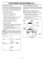
TO CHANGE ENGINE OIL (See Figs. 16 and 17)
Corrosion and dirt on the battery and temninals can cause
the battery to "leak" power.
Determine temperature range expected before oil change.
All oil must meet API service classification SF, SG or SH.
Open battery box door.
=
•
Disconnect BLACK battery cable first then RED battery cable and remove battery from tractor.
Wash battery with solution of four tablespoons of
baking soda to one gallon of water. Be careful ndtto get
the soda solution into the cells,
o
Rinse the battery with plain water and dry.
e
Clean terminals and battery cable ends with wire brush
until bright.
o
Be sure tractor is on level sudace.
,
Qit will drain more freely when warm.
Catch oil in a suitable container.
Remove oil fill cap/dipstick: Be careful not to allow dirt
to enter the engine when changing oil.
Remove drain plug.
,
Coat terminals with grease or petroleum jelly.
,
Reinstall battery (See "CONNECT BATTERY!' in the
Assembly section of this manual).
After oil has drained completely, replace oil drain plug
and tighten securely.
Refill engine with oil through oil fill dipstick tube. Pour
slowly. Do not overfill. For approximate capacity see
"PRODUCT SPECIFICATIONS"
on page 3 of this
manual.
V-BELTS
°
Check V-belts for deterioration and wear after 100 hours of
operation and replace if necessary. The belts are not
adjustable. Replace belts if they begin to slip from wear.
TRANSAXLE
Use gauge on oil fill cap/dipstick for checking level. Be
sure dipstick cap is tightened securely for accurate
reading. Keep oit at "FULL" line on dipstick.
COOLING
FILL
CAP/DIPSTICK
Keep transaxle free from build-up of dirt and chaff which
can restrict cooling.
ENGINE
LUBRiCAT!ON
Only use high quality detergent oil rated with API service
classification SF, SG or SH. Select the oil's SAE viscosity
grade according to your expected operating temperature.
OIL DRA_N
PLUG
SAE VISCOSITY GRADES
.20 °
_30o
0_
_20 o
TEMPERATURE
FilG. i7
60 _
.I0o
0_
RANGE ANTICIPATED
10 °
20 °
30 _
40 °
BEFORE NEXT OIL CHANGE
FIG. 16
18
AIR FILTER (See Fig. 18)
CLEAN
Your engine will not run properly using a dirty air filter.
Clean the foam pre-cleaner after every 25 hours of operation or every season. Service paper cartridge every 100
hours of operation or every season, whichever occurs firsL
Air screen must be kept free of dirt and chaff to prevent
engine damage from overheating. Clean With a wire brush
or compressed air to remove dirt and stubborn dried gum
fibers.
Service air cleaner more often under dusty conditions.
ENGINE
Remove knob(s) and cover.
TO SERVICE PRE-CLEANER
•
AIR SCREEN
COOLING
(See Fig. 19)
FiNS (See Fig. 19)
Remove any dust, dirt or oil from engine cooling fins to
prevent engine damage from overheating.
Stide foam pre-cteaner off cartridge.
*
Remove screws from blower housing and lift housing
and dipstick tube assembly off engine.
Squeeze it dry in a clean cloth.
.
Cover oil fill opening to prevent entry of dirt.
=
Saturate it in engine oil. Wrap it in clean, absorbent
cloth and squeeze to remove excess oil.
,
Use compressed air or stiff bristle brush to thoroughly
clean engine cooling fins.
,
If very dirty or damaged, replace pre-cteaner.
,,
To reassemble, reverse above procedure.
Wash it in liquid detergent and water.
•
Reinstall pre-cleaner over cartridge.
SCREWS
Reinstall cover and secure with knob(s).
TO SERVICE CARTRIDGE
BLOWER
HOUSING
SCREWS
,
Remove cartridge nut.
,
Carefully remove cartridge to prevent debris from
entering carburetor. Clean base carefully to prevent
debriS from entering carburetor.
',
Clean cartridge by tapping gently on flat surface. If very
dirty or damaged, replace cartridge.
AiR SCREEN
DIPST1CK
TUBE
•
Reinstall cartridge, nut, precteaner, cover and secure
with knob(s).
iMPORTANT:
PETROLEUM SOLVENTS, SUCH AS
KEROSENE, ARE NOT TO BE USED TO CLEAN THE
CARTRIDGE. THEY MAY CAUSE DETERIORATION OF
THE CARTRIDGE. DO NOT OIL CARTRIDGE. DO NOT
USE PRESSURIZED
AIR TO CLEAN OR DRY
CARTRIDGE.
ASSEMBLY.
SPARK
PLUG
COVER KNOB_
ENGINE COOLING
FIG. 19
COVER
CARTRIDGE
NUT
PAPER
CARTRIDGE
FIG, 18
19
FINS
CUSTO
RESPONSIBILITIES
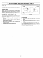
MUFFLER
CLAMP
CLAMP
Inspect and rep ace corroded muff er and spark arrester (if
equipped) as it couJd create a fire hazard and/or damage;
SPARK
PLUGS
Replace spark plugs at the beginning of each mowing
season or after every 100 hours of operation, whichever
occUrs first. Spark plug type and gap setting are shown in
"PRODUCT SPECIFICATIONS" on page 3 of this manual,
IN-LINE
FUEL FILTER
FUEL
(See Fig. 20)
FiG, 20
The fuel filter should be replaced once each season. If fuel
filter becomes clogged, obstructing fuel fl0w to carburetor,
replacement is required.
,
With engine cooi, remove filter and plug fuef line
sections.
•
•
,
CLEANING
Place new fuel filter in position in fue} tine with arrow
pointing towards carburetor.
Be sure there are no fuel line leaks and damps are
properly positioned.
Immediately wipe up any spilled gasoline.
•
Clean engine, battery, seat, finish, etc. of all foreign
matter.
,,
Keep finished surfaces and wheels free of alt gasoline,
oil, etc,
-
Protect painted surfaces with automotive type wax..
We do not recommend using a garden hose to clean ye_r
tractor unless the electrical system, muffler, air filter and
carburetor are covered to keep water out. Water in e__gi_e
can result in a shortened engine life.
20
SERVICE A
CAUTION:
•
=
,
,
,
,
ADJUSTMENTS
BEFORE PERFORMING ANY SERVICE OR ADJUSTMENTS:
Place motion control lever in neutral (N) position.
Depress ciutchlbrake pedal fui_y and set parking brake.
Place attachment ctutch in "DISENGAGED"
position.
Turn ignition key "OFF" and remove key.
Make sure the blades and ali moving parts have completely stopped.
Disconnect spark plug wire from spark plug and p_ace wire where it cannot come in contact
with plug.
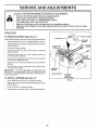
TRACTOR
TO REMOVE
MOWER
LEVER
(See Fig. 21)
Mower willbe easier to remove from the right side of tractor.
Place attachment clutch in "DISENGAGED" position.
*
Move attachment lift lever forward to lower mower to its
lowest pos tion
-
Rolf belt off engine pulley.
o
Disconnect clutch rod from clutch lever by removing
retainer spring.
Di_cQnnect anti-sway bar from chassis bracket by
removing retainer spring.
=
,
,
=
Disconnect suspension arms from rear deck brackets
by removing retainer springs.
Disconnect front links from deck by removing retainer
springs.
Raise lift lever to raise suspension arms, Slide mower
out from under tractor.
RETAINER
SPRING
IMPORTANT:
IF AN ATTACHMENT OTHER THAN THE
MOWER IS TO BE MOUNTED TO THE TRACTOR, THE
R,H. AND L,H, SUSPENSION ARMS MUST BE REMOVED
FROM TRACTOR.
TO INSTALL
•
MOWER
ANTI-SWAY
(See Fig. 21)
FIG. 21
Raise attachment lift lever to its highest position.
Slide mower under tractor with discharge guard to righl
side of tractor.
=
-
BAR
Lower lift lever to its lowest position.
Install mower in reverse order of removal instructions.
21
E
TO LEVEL MOWER
CE AN
ADJUSTMENTS
HOUSING
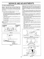
FRONT-TO-BACK ADJUSTMENT (See Figs. 24 and 25)
IMPORTANT: DECK MUST BE !EVEL SlDE-TO-SlDE. iF
THE FOLLOWING FRONT-TO-DAQK ADJUSTMENT IS
NECESSARY, BE SURE TO ADJUST BOTH FRONT LINKS
EQUALLY SO MOWER WILL STAY LEVEL SIDE-TOSIDE_
To obtain the best cutting results, the mower housing
should be adjusted so that the front is approximately
1/8"
to 1/2" tower_han the rear when the mower is in its highest
position.
Check adjustment on right side of tractor. Measure distance "D" directly in front and behind the mandrel at bottom
edge of mower housing as shown.
,
Before making any necessary adjustments, check that
both front links are equat in length. Both links should
be approximately 10-3/8".
,
If links are not equat in length, adjust one link to same
length as other link.
To lower front of mower loosen nut "E" on both front
links an equal number of turns,
When distance "D" is 1/8" to 1/2" lower at front than
rear, tighten nuts "F" against trunnion on both front
links.
,
To raise front of mower, loosen nut "F" from trunnion on
both front links. Tighten nut "E" on both front links an
equal number of turns.
When distance "D" is 1/8" to t/2" lower at front than
rear, tighten nut "F" against trunnion on both front Hnks.
•
Recheck side-to-side adjustment.
Adjust the mower while tractor is parked on level ground or
driveway.
Make sure tires are properly inflated (See
"PRODUCT SPECIFICATIONS" on page 3 of this manual).
!f tires are over or underinflated, you will not properly adjust
your mower.
SIDE-TO-SIDE ADJUSTMENT
•
(See Figs. 22 and 23)
Raise mower to its highest position.
At the midpoint of both sides of mower, measure height
from bottom edge of mower to ground. Distance "A" on
both sides of mower Should be the same or within 1/4"
of each other.
•
If adjustment is necessary, make adjustment on one
side of mower only.
•
To raise one side of mower, tighten tift link adjustment
nut on that side.
,
To lower one side of mower, loosen lift link adjustment
nut on that side.
NOTE: Each futl turn of adjustment nut will change mower
height about 1/8".
',
Recheck measurements
after adjusting.
BOTTOM EDGE
OF MOWER TO
GROUND
BOTTOM EDGE
OF MOWER TO
GROUND
MANDREL
A
FIG. 22
SUSPENSION
ARM
FIG. 24
BOTH FRONT LINKS MUST BE EQUAL iN LENGTH
LEFT UNK
ADJUSTMENT
NUT
FIG. 23
NUT "E"
NUT ' F"
FRONT LINKS
22
TRUNN1ON
FIG, 25
S
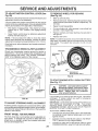
TO REPLACE
(See Fig, 26)
CE AN
MOWER
BLADE
ADJ
DRmVE BELT
;TlVlENTS
WiTH
PARKING
BRAKE
"ENGAGED"
NUT "A"
The mower blade drive be_tmay be replaced without tools.
Park the tractor on {eve{ surface. Engage parking brake.
NUT
BELT REMOVAL -
Remove mower from tractor (See "TO REMOVE
MOWER" in this section of this manual).
Work bett off both mandrel pulleys and idler pulleys,
,
Pull belt away from mower.
BELT iNSTALLATION
-
o
Install new belt in reverse order of removal
,
Make sure belt is in all pulley grooves and inside all belt
guides.
,
Ins,tail mower in'reverse order of removal instructions,
ARM
DO NOT TOUCH THiS NUT. IF FURTHER
BRAKE ADJUSTMENT IS NECESSARY
CONTACT YOUR NEAREST AUTHORIZED
SERVICE CENTER/DEPARTMENT
r
MANDREL
PU LI,.EY
FiG. 27
IDLER
PULLEYS
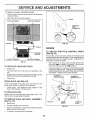
TO REPLACE
MOTION
DRIVE
BELT
(See Fig. 28)
Park the tractor on level surface, Engage parking brake,
For assistance, there is a belt installation guide decal on
bottom side of left footrest.
•
Remove mower (See "TO REMOVE MOWER" in this
section of this manuaL)
•
Remove upper belt keeper.
Remove belt from stationary idler and clutching idler,
•
MANDREL
PULLEY
•
FiG. 26
TO ADJUST
BRAKE
Pull belt slack toward rear of tractor. Carefully remove
belt upwards from transmission input puIley and over
cooling fan blades.
Pull belt toward front of tractor and remove downward
from around engine pulley.
Install new belt by reversing above procedure.
IMPORTANT:
MAKE SURE UPPER BELT KEEPER IS
POSITIONED PROPERLY BETWEEN LOCATOR TABS.
(See Fig. 27)
EN G_NE "---.._.,_= i I
Your tractor is equipped with an adjustable brake system
which is mounted on the side of the transaxle,
PULLEY
CLUTCHING
If tractor requires more than six (6) feet stopping distance
at high speed in highest gear, then brake must be adjusted.
=
Depress clutch/brake pedal and engage parking brake.
•
Measure distance between brake operating arm and
nut "A" on brake rod.
•
If distance is other than t-3/4", loosen jam nut and turn
nut "A" until distance becomes I-3/4'L Retighten jam
nut against nut "A".
•
Road test tractor for proper stopping distance as stated
above. Readjust if necessary. If stopping distance is
still, greater than six (6) feet in highest gear, further
maintenance is necessary. Contact your nearest authorized service center/department.
__
J"
_..uz-'_LV
,._f_'LOCATOR
TABS
117
"_'*_"UPPER
BELT
KEEPER
FIG. 28
23
SERVICE
TO ADJUST
Fig. 29)
MOTION
CONTROL
A
!NTS
TO REMOVE WHEEL
(See Fig. 30)
LEVER (See
The motion control lever has been preset at the factory and
adjustment should not be necessary.
FOR REPAIRS
Block up axle securely.
Remove axle cover, retaining ring and washers to allow
wheel removal (rear wheel contains a square key - Do
not lose).
if for any reason the motion control lever wilt not hold its
position while at a selected speed, it may be adjusted at the
fdction pack ]ocated on the right side of transmission.
•
Repair tire and reassemble.
-
Park tractor on levef surface. Stop tractor by turning
ignition key to "OFF" position, and engage parking
brake.
,
On rear wheels only: align grooves in rear wheel hub
and axle. insert square key.
=
Adjust motion control lever by tightening adjustment
focknut one half (1/2) turn.
Replace washers and snap retaining ring securely in
axle groove.
•
NOTE: {f for any reason the effort to move the motion
control lever becomes too excessive reverse the above
adjustment procedure by Ioosenin_ iocknut 1/4 to 1/2 turn.
Road test tractor after adjustment and repeat procedure if
necessary.
TRANSMiSSiON
Replace axle cover.
NOTE: To sea(tire punctures and prevent flat tires due to
slow leaks, tire sealant may be purchased from your locat
parts dealer. Tire sealant also prevents tire dry rot and
corrosion.
REMOVAL]REPLACEMENT
Should your transmission require removal for service or
replacement, it should be purged after" reinstatlation and
before operating the tractor. See "PURGE TRANSMISSION in the Operation section Of this manual.
I
AXLE COVER
_
SQUARE
{REAR
KEY
WHEEL
ONLY)
FIG. 30
TO START ENGINE WITH A WEAK
'See Fig, 31)
BATTERY
CAUTNON: Lead-acid batteries genero
and smoking materials away from batateexplosive
gases.
Keep
flame
teries.
A_ways
wear
eyesparks,
protection
when around batteries.
ADJUSTMENT
LOCKNUT
If your battery is too weak to start the engine, it should be
recharged. If "jumper cables" are used for emergency
starting, follow this procedure:
iMPORTANT: YOUR TRACTOR IS EQUIPPED WITHA 12
VOLT NEGATIVE GROUNDED SYSTEM. THE OTHER
VEHICLE MUST ALSO BE A t2 VOLT NEGATIVE
GROUNDED SYSTEM. DO NOT USE YOUR TRACTOR
BATTERY TO START OTHER VEHICLES.
FiG. 29
TO ADJUST
STEERING
WHEEL
ALIGNMENT
If steering wheel crossbars are not horizontal (left to right)
when wheels are positioned straight forward, remove steering wheel and reassemble per instructionsin the Assembly
section of this manual.
FRONT WHEEL
TO ATTACH JUMPER CABLES -
TOE=iN!CAMBER
The front wheel toe-in and camber are not adjustable on
your tractor. If damage has occurred to affect the front
wheel toe-in or camber, contact your nearest authorized
service centeddepartment.
*
,
24
Connect each end of the RED cable to the POSITIVE
(+) terminal of each battery, taking care not to short
against chassis.
Connect one end of the BLACK cable to the NEGATIVE (-) terminal of fully charged battery.
Connect the other end of the BLACK cable to good
CHASSIS GROUND, away from fuel tank and battery.
SERVICE
AND ADJUSTMENTS
TO REMOVE CABLES, REVERSE ORDER -
o
BLACK cable first from chassis and then from the fully
charged battery.
RED cable last from both batteries.
HOOD
POSITIVE TERMINAL
NEGATIVE TERMINAL
HEADLIGHT
WIRE
CONNECTOR
\
FiG. 32
ENGINE
TO ADJUST THROTTLE
(See Fig. 33)
CHARGED
BATTERY
POSiTiVE
TERMINAL
NEGATIVE TERMINAL
,
HEADLIGHT
*
,
With engine not running, move throttle control lever
from slow (_l,) to choke (N) position. Slowly move
lever from choke (IX]) to fast (,_) position.
*
Checkthat holes"A" in governor control fever and hole
in governor plate line-up. If holes "A" are not aligned,
loosen clamp screw and move throttle cable until holes
are aligned. Tighten clamp screw securely.
BULB
Raise hood.
Pull bulb holder out of the hole in the backside of the
grill.
,
Replace.bulb in holder and push bulb holder securely
back into the hole in the backside of the grill.
Close hood.
INTERLOCKS
CABLE
The throttle control has been preset at the factory and
adjustment should not be necessary. Check adjustment as
described below before loosening cable, tf adjustment is
necessary, proceed as follows:
FIG. 31
TO REPLACE
CONTROL
GOVERNOR
CONTROL LEVER
GOVERNOR
CONTROL PLATE
AND RELAYS
Loose 6r damaged wiring may_cause your tractor to run
poorly: stop running, or prevent it from starting.
•
check widng. See electrical wiring diagram in thd
Repair Parts section of this manual.
TO REPLACE
FUSE
Replace with 30 amp automotive-type plug'in fuse. The
fuse holder is located behind the dash.
TO REMOVE
HOOD
AND
GRILL
ASSEMBLY
(See Fig. 32)
.
Raise hood.
•
Unsnap headlight wire connector.
Stand in front of tractor. G rasp hood at sides, tilt toward
engine and lift off of tractor.
=
To replace, reverse above procedures.
HOLES"A"
CLAMP
SCREW
FiG. 33
25
THROTTLE
CABLE
SERVICE AND ADJUSTM
TO ADJUST
CARBURETOR
(See Fig. 34)
ACCELERATION
NTS
TEST
-
The carburetor has been preset at the factory and adjustment should not be necessary. However, minor adjustment may be required to compensate for differences in fuel,
temperature, altitude or load. If the carburetor does need
adjustment, proceed as follows:
=
In general, tuming idle mixture valve in (clockwise) de-,
creases the supply of fuel to the engine giving a leaner fuel/
air mixture. Turning the idle mixture valve out (counterclockwise) increases the supply of fuel to the engine giving
a richer fuel/air mixture,
High speed stop is factory
damage may result.
PRELIMINARY SETTING Air cleaner assembly must be assembled to the carburetor when making carburetor adjustments.
•
Be sure the throttle control cable is adjusted properly
(see above).
adjusted.
THROTTLE
LEVER
With engine off turn idle mixture valve in (clockwise)
closing it finger tight and then turn out (counterclockwise) 1 full turn.
FINAL SETTING Start engine and allow to warm for five minutes. Make
final adjustments with engine running and shift!motion
control lever in neutral (N) position,
=
Move throttle control lever to slow (_) position. With
finger, rotate and hold throttle lever against idle sPeed
• screw. Turn idle speed screw to attain 1750 RPM.
•
While still holding throttle lever against idle speed
screw, turn idle mixture valve in (clockwise) until engine begins to die and then turn out (counterclockwise)
until engine runs rough. Turn valve to a point midway
between those two positions: Release throttle lever.
Do not adjust
IDLE SPEED
SCREW
=
•
(,_!) to fast (_ll_)
turn idle mixture
Repeattest
and
engine acceler-
IMPORTANT:
NEVER TAMPER
WITH THE ENG{NE
GOVERNOR,
WHICH tS FACTORY SET FOR PROPER
ENGINE SPEED, OVERSPEEDING
THE ENGINE ABOVE
THE
FACTORY
HIGH
SPEED
SETTING
CAN
BE
DANGEROUS.
IF YOU THINK THE ENGINE-GOVERNED
HIGH SPEED NEEDS ADJUSTING,
CONTACT
YOUR
NEAREST
AUTHORIZED
SERVICE
CENTER/
DEPARTMENT,
WHICH HAS PROPER EQUIPMENT
AND
EXPERIENCE
TO
MAKE
ANY
NECESSARY
ADJUSTMENTS,
IMPORTANT: DAMAGE TO THE NEEDLE VALVE AND
THE SEAT IN CARBURETOR MAY RESULT IF SCREW IS
TURNED IN TOO TIGHT.
,
Move throttle control lever f!,"._mslow
pOsition, tf engine hesitates or dies,
valveout
(countercfockwise)
!i8tum.
continue to adjust, if necessary,
until
ates smoothly.
IDLE MIXTURE
VALVE
FIG. 34
26
STORAGE
ENGINE
Immediately prepare your tractor for storage at the end of
the season or if the tractor will not be used for 30 days or
more,
__side
a building
where fumes may reach an open flame
or spark.
Allow the engine to cool
FUEL SYSTEM
j
J
TRACTOR
•
Remove mower from tractor for winter storage. When
mower iS to be stored for a period of time, clean it thoroughly, lremove all dirt, grease, leaves, etc. Store in a
clean, dry area.
o
Inspect and replace belts, if necessary (See belt replacement instructions in the Service and Adjustments
section of this manual).
o
Touch up all rusted or chipped paint surfaces; sand
lightly before painting.
ENGINE
OIL
Drain oil (with engine warm) and replace with clean engine
oil. (See "ENGINE" in the Customer Responsibilities
section of this manual).
BATTERY
•
Never use engine or carburetor cleaner products in the
fuel tank or permanent damage may occur,
Use fresh fuel next season,
NOTE: Fuel stabilizer is an acceptable alternative in
minimizing the formation of fuel gum deposits during storage_ Add stabilizer to gasoline in fuel tank or storage
container: Always follow the mix ratio found on stabilizer
container. Run engine at least 10 minutes after adding
stabilizer to altow the stabilizer to reach the carburetor. Do
not drain the gas tank and carburetor if using fuel stabilizer.
Lubricate as shown in the Customer Responsibilities
section of this manual.
Be sure that all nuts, bolts and screws are securety
fastened. Inspect moving parts for damage, breakage
and wear. Replace if necessary.
Drain the fuel tank.
Start the engine and let it run until the fuel lines and
carburetor are empty.
Clean entire tractor(See "CLEANING" in the Customer
Responsibilities section of this manual).
o
IMPORTANT:
IT IS IMPORTANT
TO PREVENT
GUM
DEPOSITS
FROM
FORMING
IN ESSENTIAL
FUEL
SYSTEM PARTS SUCH AS CARBURETOR,
FUEL FILTER,
FUEL HOSE, OR TANK DURING
STORAGE.
ALSO,
EXPERIENCE
INDICATES
THAT ALCOHOL
BLENDED
FUELS (CALLED GASOHOL
OR USING ETHANOL
OR
METHANOL) CAN ATTRACT
MOISTURE
WHICH LEADS
TO SEPARATION
AND FORMATION
OF ACIDS DURING
STORAGE.
ACIDIC
GAS CAN DAMAGE
THE FUEL
SYSTEM OF AN ENGINE WHILE IN STORAGE.
Fully charge the battery for storage.
CYLINDERS
After a period of time in storage, battery may require
recharging,
To help prevent corrosion and power leakage during
long periods of storage, battery cables should be
disconnected and battery cleaned thoroughly (see "TO
CLEAN BATTERY AND TERMINALS" in the Customer Responsibilities section of this manual).
•
Remove spark plug(s).
Pour one ounce of oil through spark plug hole(s) into
cylinder(s).
-
Turn ignition key to"START" position for a few seconds
to distribute oil.
Replace with new spark plug(s).
After cleaning, leave cables disconnected and place
cables where they cannot come in contact with battery
terminals.
OTHER
-
Be sure battery drain tube is securely attached,
•
Do not store gasoline from one season to another.
-
If battery is removed from tractor for storage, do not
store battery directly on concrete or damp surfaces,
.
Replace your gasoline can if your can starts to rust.
Rust and/or dirt in your gasoline will cause problems.
If possible, store your tractor indoors and cover it to
give protection from dust and dirt.
Cover your tractor with a suitable protective cover that
does not retain moisture. Do not use plastic. Plastic
cannot breathe which allows condensation to form and
will cause your tractor to rust.
IMPORTANT: NEVER COVER TRACTOR WHILE ENGINE
AND EXHAUST AREAS ARE STILL WARM.
27
TRO
LESHOOTI
CORRECTION
PROBLEM
CAUSE
Will not start
1.
Out of fuel.
2.
3.
4.
5.
6.
7.
Engine not "CHOKED"
Engine flooded.
Bad spark plug.
Dirty air filter.
Dirty fuet filter.
Water in fuel.
'8.
9.
Loose or damaged wiring.
Carburetor out of adjustment.
10.
Engine valves out of adjustment.
Hard to start
POINTS
t.
2.
3.
4.
5.
6.
7.
properIy.
8.
9.
10.
Fill fuel tank.
See "TO START ENGINE" in Operation section.
Wait several minutes before attempting to start.
Replace spark plug.
Clean!replace air filter.
Replace fuef filter.
Drain fuel tank and carburetor, refill tank with fresh
gasoline and replace fuel filter.
Check all wiring.
See "To Adjust Carburetor" in Service Adjustments
section.
Contact an authorized service center/department.
1.
2.
3.
4.
5.
6.
7.
Dirty air filter.
Bad spark plug.
Weak or dead battery.
Dirty fuel filter.
Stale or dirty fuel.
Loose or damaged wiring.
Carburetor out of adjustment.
1.
2.
3.
4.
5.
6.
7.
8.
Engine valves out of adjustment.
8.
Clean/replace air filter.
Replace spark plug.
Recharge or replace battery.
Replace fuel filter.
Drain fue_ tank and refill with fresh gasoline.
Checkall wiring.
See "To Adiust Carburetor" in Service Adiestments
section.
Contact an authorized service centeddepartment.
Engine will not turn over
t.
2.
3.
4.
5.
6.
7.
8.
9.
Clutch/brake pedal not depressed.
Attachment clutch is engaged.
Weak or dead battery.
Blown fuse.
Corroded battery terminals.
Loose or damaged wiring.
Fautty ignition switch.
Faulty solenoid or starter.
Faulty operator presence switch(as).
1.
2_
3.
4.
5.
6.
7.
8.
9.
Depress clutch/brake pedal.
Disengage attachment clutch.
Recharge or replace battery.
Replace fuse.
Clean battery terminals.
Check all wiring.
Check/replace ignition switch.
Chec_'Jrepiace solenoid or starter.
Contact an authorized service center/department.
Engine clicks but will not
start
1.
2.
3.
4.
Weaker dead battery.
Corroded battery terminals.
Looseor damaged wiring.
Faulty solenoid or starter.
t.
2.
3.
4.
Recharge or replace battery.
Clean battery terminals.
Check aH wiring.
Check/replace solenoid or starter.
Loss of power
1.
2.
3.
4.
5.
6.
7.
8.
9.
Cutting too much grass/too fast.
Throttle in "CHOKE" position.
Build-up of grass, reaves and trash under mower.
Dirty air filter.
Low oil levelldid7 oil.
Faulty spark plug.
Dirty fuel filter.
Stale or dirty fuel.
Water in fuel.
1.
2.
3.
4.
5.
6.
7.
8.
9.
Set in _'Higher Cut" position!reduce
speed.
Adjust throttle control
Clean underside of mower housing.
Clean/replace air filter.
Check oil level/change oil.
Clean and regap or change spark plug.
Replace fuel filter.
Drain fuel tank and refill with fresh gasoline.
Drain fuel tank and carburetor, refill tank with fresh
gasoline and replace fuel filter.
Connect and tighten spark plug wire.
Clean engine air screen/fins.
Clean/replace muffler.
Check all wiring.
See "To Adjust Carburetor" in Service Adjustments
section.
Excessive vibration
10.
11.
12.
13.
14.
Spark plug wire loose.
Dirty engine air screen/fins.
Dirty/clogged muffler.
Loose or damaged wiring.
Carburetor out of adjustment.
10.
11.
12:
13.
14.
15.
Engine valves out of adjustment.
I5.
1.
2.
Worn, bent or _oose blade.
Bent blade mandrel
3.
Loose/damaged
1.
2.
3.
part(s).
28
Contact an authorized service centeddepartment.
Replace blade. Tighten blade bolt.
Replace blade mandrel.
Tighten toose part(s). Replace damaged
parts.
......
--
TROUBLESHOOTING
PROBLEM
CAUSE
Engine continues to run
when operator teavea seat
with attachment clutch
1.
Faufty operator-safety
1.
2.
•
_
POINTS
i_
"_,_'i
=
CORRECTION
presence control system.
t,
Check wiring, switches and connections,
If not
corrected, contact an authorized service center/
department.
Worn, bent orloose blade,
Mower deck not level
1.
2.
Replace blade. Tighten blade bolt.
Level mower deck.
3.
4.
Buildup of grass, leaves, and trash under mower.
Bent blade mandrel.
5.
Clogged mower deck vent holes from buildup of
grass, leaves, and trash around mandrels.
3.
4.
5.
Clean underside of mower housing.
Replace blade mandrel.
Clean around mandrels to open vent holes.
t.
2.
3.
4.
Obstruction in clutch mechanism.
Worr,Jdamaged mower drive belt.
Frozen idler puItey.
Frozen btade mandrel.
1.
2.
3.
4.
Remove
RepIace
Replace
Replace
1,
2.
Engine speed too slow.
Travel speed too fast.
3.
4,
Wet grass.
Mower deck not level.
1.
2.
3.
4.
Place throttle control in "FAST" position.
Shift to slower speed.
Allow grass to dry before mowing.
Level mower deck.
engaged
Poor
cut * uneven
Mower blades
rotate
will not
Poor grass discharge
5.
6.
7.
8.
9.
10.
tl.
Headlight(s) not working
(if so equipped)
Battery will not charge
Engine
"backfires"
when turning engine
"OFF'"
Low/uneven tire air pressure.
Worn, bent or loose btade,
Buildup of grass, leaves and trash under mower.
Mower drive belt worn.
Blades improperly installed.
Improper btades used,
Ctogged mower deck vent holes from buildup of
grass, leaves, and trash around mandrels.
5.
6.
7.
8.
9.
10.
tl.
obstruction.
mower drive belt.
_d_erpulley.
Made mandret.
Check tires for proper air pressure.
Replacelsharpen blade. Tighten blade bolt.
Clean underside of mower housing.
Replace mowerdrive belt.
Reinstati blades sharp edge down.
Replace with blades listed in this manual.
Clean around mandrels to open vent holes.
1.
Switch is "OFF".
1.
Turn switch"ON".
2.
3.
4.
5.
Bulb(s) burned out.
Faulty light switch.
Loose or damaged wiring.
Blown fuse.
2.
3.
4.
5.
Replace bulb(s).
Check/replace light switch.
Check wiring and connections.
Replace fuse.
1,
2.
Bad battery ceil(s).
Poor cable connections.
1.
2.
Replace battery.
Check/clean all connections.
3,
4.
Faulty regL_lator (if so equipped).
Faulty alternator.
3.
4.
Replace regulator.
Replace alternator.
1.
Engine throttle control not set at "SLOW"
position for 30 seconds before stopping engine.
1.
Move throttle control to _'SLOW" position and allow
29
to idte for 30 seconds before stopping
engine.
_ _ _'!'i_
CE NOTES
3O
TRACTOR
- = MODEL NUMBER
917,258531
SCHEMATIC
o÷1
I11o
1°
RED
BLACK
BATTERY
RED
RED
AMMETER
(OPTIONAL)
WHtTE
SOLENOID
RED
"
S
)G
L )-
IGNITION
SWITCH
BLACK
_
IGNITION SWITCH
POSITION
RCUI,
TI
OFF
|G+M+LI
RUNiLIGHTI
B+L
--_/*
_
s_ARTtB:d+sl
|
NONE
A+Y
F NONE
.O.E
METER
HOUR
)
NOTE
YOUR TRACTOR IS
EQUIPPED WITH A SPECIAL
BROWN
ALTERNATOR SYSTEM.
THE LIGHTS ARE NOT
CONNECTED TO THE
BATTERY, BUT HAVE THEIR
OWN ELECTRICAL SOURCE.
BECAUSE OF THIS, THE
BRIGHTNESS OF THE LIGHTS
WILL CHANGE WITH ENGINE
SPEED, AT IDLE THE LIGHTS
@
WILL DIM. AS THE ENG)NE IS
NON-REMOVABLE
SPEEDED UP, THE LIGHTS
CONNECTIONS
WILL BECOME "THEIR BRIGHTEST.
HEADLIGHTS
.....O- .... _:
REMOVABLE
CONNECTIONS
WIRING INSULATED CLIPS
NOTE: IF WIRING INSULATED CLIPS WERE REMOVED FOR
SERVICING OF UNIT, THEY SHOULD BE REPLACED TO
PROPERLY SECURE YOUR WIRING.
31
7
REPAIR PARTS
TRACTOR
- - MODEL NUMBER
917.258531
ELECTRICAL
70
I
I
I
I
\
\
\
/
/
1
/
/
i
32
1
!
/
32
REPAIR PARTS
TRACTOR
.. - MODEL
NUMBER
917.258531
ELECTRICAL
KEY
NO.
PART
NO.
1
2
3
4
6
7
8
9
16
19
20
21
146139
74760412
STD551025
STD551125
STD54!025
109238X
156417
109596X
t53664
STD551 !25
73350400
147430
22
24
25
4152J
4799J
146147
26
28
29
30
31
32
33
40
41
42
43
44
45
52
70
108824X
4207J
121305X
140301
124211X
141226
1093t0X
156442
71110408
131563
145673
73640400
121433X
141940
140422
NOTE:
DESCRiPTiON
Battery 12 Volt 25 Amp
Bolt, Hex Head 1/4-o20unc x 3/4
Washer
Washer
Nut
Tube, Plastic, 12"
Case, Battery Mech Hinge
Clamp, Hose
Switch, interlock Pushqn
Washer, Lock
Nut, Hex, Jam 1/4-20 UNC
Harness, Light Socket
(Includes 4! 52J)
Bulb, Light
Cable, Batter1,, 6 Gauge, Red, 1i"
Cable, Battery, 6 Gauge, Red, W/t6
Wire
Fuse, 30 Amp
Cable, Ground, 6 Gauge, BLack, !2"
Switch, Ptunger
Switch, ignition
Nut, Ignition
Cover, Key Switch
Key, ignition
Harness, Ignition
Bolt, Hex Head, Fin. t/4-20 x 1/2
Cover, Terminal, Red
Solenoid
Nut Keps Btk Hex 1/4-.20 UNC
Ammeter Rectangular 6 Amp
Protection Wire Loop
Harness Engine B&S
A]t component dimensions
1 inch = 25.4 mm
33
given in U.S. inch_:_s
REPAIR PARTS
TRACTOR
CHASSIS
- -MODEL
NUMBER
917.25853!
AND ENCLOSURES
29
28
12
53
31
51
55
57
\
54
3
14
34
REPAIR PARTS
TRACTOR
CHASSIS
=- MODEL
NUMBER
917.258531
AND ENCLOSURES
KEY
NO.
PART
NO.
1
2
3
4
5
9
10
11
12
13
14
17
18
25
26
28
29
30
31
38
39
5t
52
53
54
55
57
60
64
7!
74
140
142
143
144
145
146
147
--
159527
140356
17490612
19131216
155272
!50156X011
STD533710
146956
145660
146962
17490608
144983X558
126938X
19131312
STD54!437
t45198X558
145200
151287X558
139976
139886
139887
73800400
19091416
145201
17030814
145202
STD522507
STD533707
154798
73680400
STD541437
150556
156095
154968
154207
156524
154334
74760412
5479J
NOTE:
DESCRIPTION
Chassis Assembly
Drawbar
Screw, Thd. Roll 3/8-16 x 3/4
Washer 13/32 x 3/4 x 16 Gauge
Bumper Hood!Dash
Dash
Bolt, Carriage 3/8-16 x 3/4
Pane!, Dash, LH.
Clip Tinnerman Grille PiL
Panel, Dash, R.H_
Screw Thdrot 3/8-16 x 1/2
Hood Assembly
Bumper Hood
Washer 13/32 x !3/16 x I2 Gauge
Nut
Gdile w!Ctips MS-558
Lens, Grille
Fend/Ftrest Pnt STLT N HLD 558
Bracket, Fender Support
Pivot Bracket Assembly, L.H.
Pivot Bracket Assembly, R.H.
Nut Look w/Insert 1/4-20 UNC
Washer 9/32 x 7/8 x 16 Ga.
Brack_t Grille Pickoff LH
Screw Spiderlock Hex Hd #8-7/8
Bracket Gd]te Pickoff RH
Bolt, Fin Hex !/4,-20 UNC x .75
Belt Rdhd Sqnk 3/8q 6 UNC x 3/4
Dash _ower STLT
Nut, C_wnlock 1/4,-20 UNC
Nut Crownlock 3/8-16 UNC
Bracket Chassis Front
Plate Reinforcement STL'T
Bracket Swaybar Chassis
Bracket Pnt Footrest STLT
Rod Pivot Chassis/Hood
Screw Torx Hd Thd 5/t 6-18 UN-2A
Bolt, Hex Hd t/4-20 UNC x 3/4
Plug, Button
Afl component dimensions given in U.S. inches
! inch = 25.4 mm
35
REPAIR PARTS
TRACTOR
MODEL NUMBER
917.258531
DRIVE
116
61
i/48
36
32
37
36 35
53
61
!
16
I
84100
27
77
105
10o
78
74 _"
36
REPAIR PARTS
TRACTOR
- = MODEL
NUMBER
9i7o258531
DRIVE
KEY
NO.
PART
NO.
t
2
3
8
10
15
16
I8
t9
21
22
24
25
26
27
28
29
30
3t
32
34
35
36
37
38
39
40
41
42
47
48
49
50
51
52
53
55
56
57
59
61
62
t50071
142431
143995
I54.792
STD561210
74490544
STD54143I
STD523710
STD541437
130564
145627
73350600
106888X
STD551037
76020412
145204
124236X
130807
127275X
STD523107
155071
120183X
STD551062
STD571810
123674X
STD523727
4470J
t 54777
19131312
127783
154604
123205X
STD523715
STD541437
STD541431
105710X
105709X
STD523712
140294
140312
17490612
8883R
DESCRtlPTION
Transaxte Assembly
Spring, Return, Brake
Putley, Transaxie
Rod Shift Fender
Pin Cotter 1/8 x 1 CAD
Bolt Hex Ftghd 5/16-18 Gr. 5
Nut Lock HexWilns.
5/16-18 Unc
Bolt Fin Hex 3/8-16 Uncx t Gr. 5
Nut Lock HexWiWsh
3/8-16 Unc
Knob, Deluxe 1/2-13
Rod, Brake Hydro
Nut, Hex Jam 3/8-16 Unc
Spring, Brake Rod
Washer
Pin Cotter 1/8 x 3/4 CAD.
Rod, Parking Brake
Cap, Parking Brake
Bracket, Transaxle
Keeper Belt Lh
Bolt Hex Hd 5/16-18 Uncx 3/4
Shaft, Foot Pedal
Bearing, Nylon
Washer
Pin, Roll
PuJiey, Idler, Flat
Bolt
Spacer, Split
Keeper, Belt Retainer
Washer 13/32 x 13/16 x 12 Gauge
Pulley, idler, V-Groove
BellcrankAssembtyClutch
Retainer, Belt
Bolt
Nut Crownlock 3/8-16 UNC
Nut, Crownlock 5/16-18 Unc
Link, Clutch
Spring, Return, Clutch
Bolt Hex 3/8_16 x 1-1/4
V-Belt, Ground Drive
Keeper, Center Span
ScrewThdrot. 3i8q6x3/4Ty.
TT
Cover, Pedal
KEY
NO,
PART
NO,
63
64
65
66
69
70
71
72
73
74
75
76
77
78
8t
82
83
84
86
87
88
89
9t
92
93
94
95
96
97
98
'!00
!02
!03
104
105
106
116
118
121
140186
71!70764
STD55114.3
154778
142432
134683
140158
19132012
156347
121199X
121749X
12000001
123583X
121748X
156046
123782X
19171216
140548
71208
19212016
12000008
154882
74780536
74780524
142564
140462
144643
STD624003
140469
.73510600
19111216
141322
73940800
140156
71070516
74780520
72110610
154774
154419
DESCRiPTiON
Pulley, Engine
Bolt 7/16-20 X 4 Gr. 5
Washer Lock Hvy Htc! Sp_ 7/t6
Keeper Belt Engine
Screw
Keeper Belt Engine
Strap Torque Lh Hydro 18/20" 'T
Washer 13/32 x !-t/4 x 12 Gauge
Strap Torque Rh Hydro
Spacer, Split
Washer 25/32 x 1-1/4. x 16 Gauge
E-Ring
Key, Square
Washer 25/32 x 1-5/8 x 16 Gauge
Shaft Asm. Cross Hydro 20" "Tires
Spring Torsion TiA
Washer 17/32 x 3/4 x 16 Ga,
Rod, Tie Hydro 20" Tires
Bushing Rod Strig. 629/632 ID
Washer 21/32 x 1-!/4 x !6 Ga.
Ring Ktip #5304-62
Console, Shift
Bott Fin Hex 5/16-18 x 2-!/4
Bolt Fin Hex 5/6-18 UnC x 1-I/2
Line Fuel Hydro 4"
Fan, Hydro 7"
Controt Bypass Hydro 20" Tires
"Retainer Spring 1" Zinc/Cad
Keeper Boit Rh Hydro 0750. 18/20"
Nut Keps Hex 3/8_16 Uric
Washer 11/32 x 3/4 x !6 Ga.
Washer BelMlle .501D x 1.50D
Nut Hex Jam Toplock 1/4_20 Unf
Arm, Control Hydro
Screw Cap Hex 5/16 x 18 x 1
Bolt Fin Hex 5/16-18 Uric x 1_1/4
Bolt Rdhd Sqnk 3/8-16 x 1.25
Spacer Belicrank
Nyliner Clutching STL
NOTE: All component dimensions given in U.S. inches
1 inch = 25.4 mm
37
REPAIR PARTS
TRACTOR
STEERING
- - MODEL NUMBER
917.258531
ASSEMBLY
......
_-_,_2_--_1
. . "22-_2222 "-.
[
L
l
I
62
11
i!J_7
i
i,
67
68
13
65
25
15
68
30
38
\
REPAIR PARTS
TRACTOR
STEERING
- MODEL NUMBER
9!7.258531
ASSEMBLY
KEY
NO.
PART
NO.
1
2
3
4
5
6
7
8
9
10
11
13
15
16
17
18
19
20
21
22
139768
154427
156483
157473
6266H
121748X
19272016
12000029
3366R
156438
STD551137
154779
73901000
132624
156546
57079
124035X
126684X
STD551125
71100410
23
25
26
27
28
29
30
32
36
37
38
39
40
41
42
43
44
46
47
51
54
62
63
65
66
67
68
127501
154406
126847X
136874
19131416
17490612
STD561210
130465
155099
152927
139769
19133808
STD541537
t00711L
145054
121749X
153720
121232X
6855M
STD541431
74780520
156594
STD523710
154780
154404
74781044
154429
DESCRIPTION
Steering Wheel
Axle Assembly STMP Dropped STL
Spindle Assembly, L,H.
Spindle Assembly, R,H.
Bearing, Race, Thrust, Hardened
Washer 25/32 x 1-.5/8 x 16 Gauge
Washer 27/32 x 1-1/4 x 16 Gauge
Ring, Klip
Bearing, Steering Co}umn
Draglink Extended Stamped
Washer, Lock
Bearing Axle STLT/GT
Nut, Lock, Flange 5/8q I UNC
Pin, Axle 5/8 x 1.55/1.54
Shaft Assembly, Steering
Washer, Thrust .515 x .750 x .033
Support, Shaft
Washer, Shim t/4 x 5/8 x .062
Washer
Screw, Hex Socket Head
1/4-20 x 5/8
Pittman Shaft Assembly
Bracket, Steering
Bushing, Link, Drag
Gear, Sector
Washer I3/32 x 7/8 x t6 Gauge
Screw, Thd., Roll. 3/8-16 x 3/4.
Pin
Rod, Tie
Bushing, Steering
Screw
Inse_t Steering Wheel
Washer 13/32 x 2-3/8 x 8 Gauge
Gripco Nut
Adaptor, Steering Wheel
Boot, Steering Shaft
Washer 25/32 x 1-I/4 x 16 Gauge
Extension Shaft Steering LR.LT
Cap, Spindle
Fitting, Grease
Nut Lock Hex w/ins. 5/16-18 UNC
Bolt Fin Hex 5/16-t8 UNC x 1-I/4.
Kit Steering Asm Set_Tice
Bolt, Fin Hex 3/8-16 UNC x I Gr 5
Spacer Axte
Bearing Arm Pittman
Bott, Fin Hex 5/8-11 UNC x 2o3/4
Axle, Brace
NOTE: A component d mensions given in U.S. inches
! inch = 25.4 mm
39
REPAIR PARTS
TRACTOR
- - MODEL
NUMBER
917.258531
SEAT ASSEMBLY
8 -...,__f
8
21
2°\
/t6
KEY
NO.
PART
NO.
1
2
3
4
5
6
7
8
9
10
12
13
14
14O123
140551
STD523710
19131610
145006
STD541437
124181X
17490616
19131614
155925
12t246X
121248X
72050411
DESCRIPTION
Seat
Bracket, Pivot, Seat
Bolt
Washer 13/32 x I x 10 Gauge
Clip, Push-In Hinged
Nut
Spring, Seat
Screw, Thd, Rotl. 3/8-16 x 1
Washer 13/32 x 1 x I4 Gauge
Pan, Seat Emboss QCK Conn.
Bracket, Switch Mounting
Bushing, Snap
Bolt, Carriage 1/4-20 x 1-3/8
KEY
NO.
PART
NO.
15
16
t7
21
22
23
134300
121250X
123976X
153236
STD541431
74780814
24
25
26
19171912
t27018X
STD551150
DESCRIPTION
Spacer, Split .28 x .88
Spring
Locknut, Flange 1/4 Grade 5
Bolt, Shoulder 5/16-18 UNC
Nut
Bolt, Hex Head, Fin.
I/2-I3 x 7/8 Grade 5
Washer 17/32 x 1-3/16 x 12 Gauge
Bolt, Shoulder 5/16-18 x .62
Washer, Lock
NOTE: All component dimensions given in U.S. inches
1 inch = 25.4 mm
40
REPAIR PARTS
TRACTOR
° o MODEL
NUMBER
9!7.25853!
DECALS
13
9
2
6
t
3
18
7
7
10
!8
20
21
2!
!2
13
14
KEY
NOo
1
2
3
4
6
7
8
9
10
12
PART
NO.
156811
!50333
151299
151300
133644
I50927
156787
146709
156439
146046
WHEELS
KEY
NO,
DESCRIPTION
Decal,
DecaI,
Decal,
Decal,
Decal,
Decat,
Decal,
Deca},
Decal,
Decal,
Oper. tnstr.
Cap Cnsmr Help Line
Hood, R.FI.
Hood; L.H.
Customer Maintenance
Side Panel
Deck Mower EZ3
Fender, Craftsman
Fender Danger
V-Belt Drive Schematic
13
14
18
20
2t
-.-----_
& TIRES
KEY
NO.
PART
NO.
147138
!36832
151708
149516
156810
I383!1
t4234t
I54515
154516
159850
159851
PART
NO,,
5
6
7
8
9
10
106732X427
278H
9040H
106108X427
122082X
7152J
I!
_-
!04757X
144334
OESCR_PTtON
Deca_, Chassis, 6 Speed/42"
Decal, WBelt Schematic
.Deca;, tns. Hood
Decal, Battery DnglYPsn Ei_.g
Decal, Fender A_uto
Decal, Lift Handle
Decal Drawbar Chtd Mvt Hyd LT
Pad Footrest LH STLT
Pad Footrest RH STLT
Owner's Manual, English
Owner's Manual, Spanish
OESCR_PTiON
Valve Cap, Tire
Stem, Valve
Tire, Front
Tube, Front Tire
(Not Provided, Service Item Only)
Rim, Front
Fitting, Grease (Front Wheel O_fly)
Bearing, Flange (Front Wheei On!y)
Rim, Rear
Tire, Rear
Tube, Rear Tire
' #, i .....
_-'_,,Or'dy)
(Not Provided, o
oervlc:,
Cap, Axle
Sealant, Tire 10 oz.
NOTE: All component dimerls.:ioris given in U.S i.-_d"es
1 inch = 25.4 mm
41
REPAIR PARTS
TRACTOR
- - MODEL
NUMBER
917.25853!
ENG1NE
3
72
13
[
14
15
6
38
J
78
33
37
23
29
\
OPTIONAL
EQUUPMENT
Spark Attester
42
REPAIR PARTS
TRACTOR
- = MODEL
NUMBER
917.258531
ENGINE
KEY
PART
NO,
NO.
150600
17720410
4
13
14
15
16
23
29
31
32
33
35
37
38
137352
272293
13280324
13200300
STD551237
156123
137180
109202X
123549X
123487X
17490512
137040
.......
40
44
!24028X
17490412
46
62
72
78
81
19091416
STD551131
71070512
17490620
128861
DESCRIPTION
Controt, Throttle
Screw, Hex Head, Thread Cutting
1/4-20 x 5/8
Engine (See Breakdown) Briggs
Model 28N707-0173-0t
Muffler
Gasket, Exhaust
Nippte, Pipe 3/8 NPT x 3
Elbow, Standard 90 °, 3/8-t6 NPT
Washer
Shield, Heat
Arrestor, Spark
Tank, Fuel
Cap Assembly, Fuel Tank, Vented
Clamp, Hose
Screw Thdrol 5/16-18 x 3_4 Tyt
Line, Fuel
Plug, Oil Drain
(Order From Engine Manufacturer)
Bushing, Snap, Fuel Line
Screw, Hex Washer Head, Thd., Roll.
1/4-20 x 3/4
Washer 9/32 x 7/8 x 16 Gauge
Washer, Lock
Screw, _-iex Cap Head 5/16-18 x 3/4
Screw, Thd., Roll. 3/8-16 x t-1/4
Nut Flange t/4-20 Starter Nut
NOTE: All component dimensions given in U.S. inches
1 inch = 25.4 mm
43
REPAIR PARTS
TRACTOR
MOWER
- - MODEL
NUMBER
917.258531
LiFT
5
30
3
13
26
4
6
11
5
12
13
19
13
161718
32
19
!5
32
44
20
REPAIR PARTS
TRACTOR
MOWER
= - MODEL
NUMBER
917.258531
LIFT
1
2
3
4
5
6
7
8
10
11
12
13
15
16
17
18
159471
159460
I05767X
12000002
19211621
120183X
125631X
122365X
1225!2X
139865
139866
STD624008
127218
73350800
130171
73800800
19
20
23
24
25
26
27
28
29
30
31
32
49
139868
STD624008
110807X
191310!6
2876H
76020308
12697IX
73350600
138057
150233
140302
73540600
145212
NOTE:
Lift Lever Inner Wire Assembly
Shaft Assembly, Lift
Pin, Groove
E_Ring
Washer 21/32 x I x 21 Gauge
Bearing, Nylon
Grip, Handle, Fluted
Button, Plunger, Red
Spring
Link, Lift, L.H.
Link, Lift, R.H.
Retainer Spring
Link, Front
Nut, Hex, Jam !/2-13 UNC
Trunnion
Locknut, Hex, with Washer Insert
1/2-13 UNC
Arm, Suspension, Rear
Retainer Spring
Nut, Special
Washer 13/32 x 5/8 x 16 Gauge
Sprin9
Pin, Cotter 3/32 x 1/2
Rod, Adjust, Lift
Nut, Hex, Jam 3/8-16 UNC
Knob, !nfinite Height Adjustment
Trunnion, lnf Height
Beating, Pvt, Lift Spherical
Nut, Crownlock 3/8-24
Nut Hex Ftange Lock
All component dimensions given in U.S. inches
t inch = 25.4 mm
45
REPAIR PARTS
TRACTOR
MOWER
- = MODEL
NUMBER
917.258531
DECK
76
74
84
!03
t05
102
34
.33
32
106
58
1
\
2
27
\
46
\
REPAIR PARTS
TRACTOR
MOWER
- - MODEL
NUMBER
917.25853!
DECK
KEY
NO,
PART
NO.
1
2
3
4
5
6
8
9
10
11
12
13
144393
STD533107
138017
138440
STD624008
130832
850857
STD551137
140296
134149
129895
137645
14
15
16
17
18
19
20
21
22
23
24
25
26
27
28
29
30
3t
32
33
34
35
36
37
40
4t
43
44
45
46
48
49
50
5t
52
53
54
55
128774
t!0485X
140329
72110610
STD533106
132827
136888
STD54143t
134753
131267
105304X
t23713X
110452X
"130968
19111016
131491
138776
129963
153535
137266
STD533717
133835
131494
STD551037
STD541437
133551
"140083
140088
STD624003
137729
133944
133940
131340
STD541410
139888
131845X900
133943
140084
DESCRIPTION
Mower Housing
Bolt
Bracket Assembly,Sway Bar, Front
Bracket Assembly, Sway Bar
Retainer Spring
Arm, Suspension, Rear
Bolt, Hex 3/8-24 x 1.25 Grade 8
Washer, Lock
Washer, Hardened
Blade, Mulching
Bearing, Ball
Shaft Assembly, Mandrel, Vented
(Includes Key Number 6)
Housing, Mandrel, Vented
Bearing, Ball, Mandrel
Stripper, Vented Mower Deck
Bolt, Carriage 3/8-16 x 1-1/4
Bolt, Carriage 5/16-t8 x 5/8
Bolt, Shoulder
Baffle, Vortex
Nut Crownlock 5/16-18 UNC
Stiffener Bracket
Bracket, Deflector
Cap, Sleeve
Spring, Torsion, Deflector
Nut, Push
Shield, Deflector
Washer 11/32 x 5/8 x 16 Gauge
Rod, Hinge
Screw Thdrol Hex Head Zinc Mwr
Washer, Spacer
Pulley, Mandrel
Nut, Toptock, Flanged
Bolt
Fastner, Christmas Tree
Pulley, Idler, Flat
Washer 13/32 x 13/16 x 16 Gauge
Nut Crownlock 3/8-16 UNC
Rod, Pivot, with Nibs
Rod, Clutch, Secondary, with Nibs
Guard, Mandref, L.H.
Retainer
Screw, Thd. Roll 1/4-20 x 5/8
Washer, Hardened
Roller Assembly, Cam Follower
Bolt, Shoulder #10-24 Grade 5
Locknut
Bolt, Shoulder 5/16-I8 UNC
Arm Assembly, Pad, Brake
Washer, Hardened
Arm, Idler
KEY
NO.
PART
NO.
56
58
59
67
68
71
72
73
74
75
76
77
78
79
80
81
82
84
92
10I
102
103
104
105
106
1!1
112
113
t 14
115
116
117
!18
119
121
128
129
t30
131
t32
122052X
140086
14!043
149846
144959
I4.2427
131870
127847
121748X
12000029
128903
127845
154809
127498
153701
73350600
142028
158824
STD541437
136420
71161010
19061216
STD55II10
130758
2029J
155197
155198
17490512
STD541431
72t10504
137644
133957
73930600
19121414
143723
153390
19131312
STD523710
STD533710
19132203
o-
130794
--
159481
DESCR_PTgON
Spacer, Retainer
Spring, Torsion Brakes
Guard, TUV Idler
Knob Custom Ovat
V-Bek
Rod, Clutch, Primary, with Nibs
Spring, Return
Arm, Clutch, Secondary
Washer 25/32 x t-5/8 x 16 Gauge
Ring, Klip
Bolt, Shoulder 3/8-16 UNC x 1.44
Keeper, Spring
Lever Asmo Clutch Pri Ptm STLT
Bushing, Large, Brass
Spring, Mower Clutch
Nut, Hex Jam 3/8-16 Unc
Trunnion, Adj.
Bracket Asm idler
Nut
Mulcher Cover
Screw
Washer #10
Washer, Lock
Latch Assembly, Bagger
Nut, Weld
Bracket, Gauge, Wheel L.H.
"Bracket, Gauge, Wheel R.H.
Screw Thdro! 5/!6-18 x 3/4
Nut, Hex, Keps 5/16_18 UNC
Bolt, Carriage 5/16 UNC x 1/2
Bolt, Shoutder
Wheet, Gauge
Nut, Center]ock 3/8-16
Washer 3/8 x 7/8 x t4 Gauge
Bracket
Washer Fett
Washer !3/32 x 13/16 x 12 Ga.
Bolt, Fin Hex 3/8-16 UNC x 1 Gr_ 5
Bolt, RDHD SQNK 3/8-t6 UNC x 1
Spacer, Washer 13/32 I.D. x 1-3/8
O.D. x !/4
Mandrel Assembly (Includes Key
Numbers 8-10, 12-!5, 31 and 32)
Mower Deck, Complete (Standard
Deck, Order Separately Mutcher
Plate and Gauge Wheel
Components, Key Nos. 10I-.106
and 111-121)
NOTE: All component dimensions given in U.So inches
1 inch = 25.4 mm
47
REPAIR PARTS
TRACTOR
HYDRO
GEAR
TRANSAXLE
- = MODEL NUMBER
- MODEL
NUMBER
917.258531
310-0650
58
139
34
59
9!
26
23
9O
44
9O
52
91
4
5
t
35
1t3
48
REPAIR PARTS
TRACTOR
HYDRO
GEAR
TRANSA×LE
o - MODEL
NUMBER
- MODEL NUMBER
917.258531
310-0650
KEY PART
NO. NO.
DESCRiPT!ON
KEY PART
NO. NO.
DESCRmPTJOH
1
2
3
4
5
6
7
8
9
13
14
15
17
18
t9
23
24
25
26
27
28
29
34
35
36
37
38
39
142930
142931
142932
142928
142933
142934
142935
150771
I42937
142938
142939
142940
142941
150772
150773
142944
142945
142946
150774
142948
142949
142950
142951
142952
142953
142954
142955
150777
Housing, Lower
Assembly, Upper Housing
Seat, Lip
Ring, Wire Retaining
Ring, Retaining
Bearing, Shaft Bail
Bearing, Cradle
Bearing, Thrust 30 x 52 x 13
Swashptate, Variable
Block, Cylinder Assembly
Arm, Trunnion
Seat, Lip
Guide, Slot
Shaft, Motor
Bearing, Thrust 42 x 68 x 16
Block, CyiinderAssembly
Seal, Lip t0 x 25 x 7
Actuator, Bypass
Center Section Assembiy Kit
Seal, Lip 26 x 42 x 8
Ring, Retaining
Washer 26 x 35 x 1
Oil Filter Element
Arm, Bypass
Ring, Retaining
Arm, Actuating
Pin, Actuating
Bolt 5/16-24 x 1-3/4
43
44
52
53
56
58
59
62
63
64
68
69
83
85
88
89
90
91
92
93
I t3
ti4
1!9
134
135
139
140
Washer 7/t6 x 7/8 x .060
DifferentialAssembly
Washer 3/4 x !.5 x .13
Seal .75 x 1.25 × .250
Shaft, Input
Bolt t/4-20 x !.38
Pin .5 OD x.43 fD x .750
Arm, Contro{
Puck, Dampener
Set Screw
Spr}ng
Stud 5/16-24
Jackshaft Assembly
Jackshaft
Screw, Cap
Washer '7/16 x 1 x '1/2
Sleeve Bearing
Seal, Wiper
Spring, B_ock
Washer, BtockThrust
Cap, Vent Assembly
Fitting, O°Ring Assembly
Spacer
Nut, Castle 5/t6_24
Pin, Cotter
Spring, Compression
Nut, Hex 5/16-24
40
41
150778
142958
Locknut, Fiex 5/t6-24 UNJC
Brake Rotor/Stator Kit
NOTE:
49
142884
150829
142991
142961
142963
142964
142965
142966
142967
t42920
142969
144610
142971
150806
142973
142974
142975
142976
142977
142978
142917
142918
14.2980
144607
144608
150775
150776
A!! component dimensions given in U.S i_'_ches
! inch = 25.4 mm
REPAIR PARTS
TRACTOR
BRIGGS
& STRATTON
=- MODEL NUMBER
ENGmNE o MODEL
NUMBER
28N707,
917,25853t
TYPE NUMBER
0!73=01
230
_614
635
238
337
3°@
0
7
305
5O
REPAIR PARTS
TRACTOR
BRIGGS
& STRATFON
121 CARBURETOR
ENGINE
- - MODEL NUMBER
= MODEL NUMBER
OVERHAUL
28N707,
9i7.258531
TYPE NUMBER
0173o01
KiT
0
15
!37
52
_" REQUIRES SPECIAL TOOLS
TO INSTALL. SEE REPAIR
iNSTRUCTiON MANUAL.
51
REPAIR PARTS
TRACTOR
BRIGGS
& STRATTON
ENGINE
- ° MODEL NUMBER
- MODEL
NUMBER
28N707,
9!7.258531
TYPE NUMgER
0173=01
_284A
535
445
5!
138
@
!37
977 CARBURETOR
GASKET
468
305_
346
334
,37
52
REPAIR PARTS
BRIGGS
& STRATTON
TRACTOR
_ _ MODEL NUMBER
ENGINE
NUMBER
- MODEL
917.258531
28N707,
TYPE NUMBER
0173-01
209
801
783
729A
1090
311
803
544
53
REPAIR PARTS
BR1GGS & STRATTON
TRACTOR
o - MODEL NUMBER
ENGINE
NUMBER
= MODEL
KEYPART
NO. NO.
1
2
3
5
7
8
9
10
11
12
13
!5
16
18
20
22
23
24
25
26
27
28
29
496412
399265
391086
495858
272614
495735
27803=
94621
281246
271916
271997
271996
94728
94239
495162
94196
494238
291675
94624
492326
222698
495860
495977
495978
495979
495854
495852
495851
495855
260924
299691
391286
494504
495490
32
32A
33
34
35
37
40
45
46
5t
94695
94648
495856
495857
262811
224502
224641
262411
496884
272465
52
272569
53
75
78
94637
224061
94832
917.258531
28N707,
KEY PART
NO. NO.
DESCRiPTiON
Cylinder Assembly
Bearing, Cylinder
* Sea_, Oil
Head, Cylinder
*** Gasket, Cylinder Head
Breather Assembiy
* Gasket, Valve Cover
Screw, Seres
Tube, Breather
* Gasket, Crankcase Cover, .015"
* Gasket, Crankcase Cover, .005"
* Gasket, Crankcase Cover, .009"
Screw, Cylinder Head
Plug, Oil Drain
Crankshaft
Timing GearKey
Base, Engine
*Seal, Oil
Screw, Seres Base Mounting
Flywheel and Ring Gear Assembly,
Magneto
Key, Flywheel
Piston Assembly, Standard Size
Piston Assembly, .010" Oversize
Piston Assembly, .020" Oversize
PiSton Assembly, .030" Oversize
Ring Set, Piston, Standard Size
Ring Set, Piston, .010" Oversize
Ring Set, Piston, .020" Oversize
Ring Set, Piston, .030" Oversize
Lock, Piston Pin
Pin Assy., Piston, Standard Size
pin Assy., Piston, .005" Oversize
Rod Assembly, Connecting
Rod Assembly, Connecting,
.020" Undersize Crankpin Bore
Screw, Hex Washer Head, 1-57/64
Screw, Hex Washer Head, 1-5/8
Valve, Exhaust
Vaive, Intake
Spring, Valve
Guard, Flywheel
Retainer, Valve Spring
Tappet, Valve
Gear, Cam
.... Gasket, Carburetor (Carburetor to
Elbow) (Also _ncluded in Gasket
Set, Part Number 495993)
*** Gasket, Carburetor
(Elbow to Cylinder)
Stud, Carburetor Mounting
Washer, spring
Screw, Pan Head
95
98
104
105
106
108
117
118
121
123
125
127
t30
131
133
137
138
141
142
147
164
166
171
t87
188
192
201
209
216
219
222
224
225
227
230
232
238
240
265
284
*
**
94098
495800
231789
231855
231854
224540
231858
495932
498116
94616
498051
--224539
494379
494381
281165
281164
495931
231859
497472
214047
94555
281051
393815
94627
492160
262767
260695
262766
490815
495611
94729
495157
493935
94742
262785
262836
394358
221535
94704
TYPE NUMBER
0173-01
DESCRIPTION
** Screw, Throttle
Screw, Idle Speed
** Pin, Float Hinge
- Valve Float
** Seat, Inlet Valve
Valve, Choke
** Jet, Needle Valve
Valve, Needle
Carburetor Overhaul Kit
Screw, Elbow Mounting
Carburetor Assembly
** Plug, Welch (Sold in Kit Only)
Valve, Throttle
Shaft and Lever, Throttle
Float, Carburetor
.... Gasket, Float Bowl
.... Washer, Bowl
Shaft and Lever, Choke
** Nozzle, Carburetor
** Pilot, Jet
Elbow, Carburetor
Stud, Rocker Arm
Nut, Air Cleaner Mounting
Line, Fuet (11" Long, Cut to Suit)
Screw, Sems
Screw Assembly, Rocker Arm
Link, Governor
Spring, Governor
Link, Choke
Gear, Governor
Plate, Governor Control
Screw, Seres, Air Cleaner
Crank, Governor
Lever Assembly, Governor
Washer_ Governor Crank
Spring, Governor Link
Cap, Valve
Filter, Fuel (in Fuel Line)
Clamp, Casing
Screw, Hex Head
Included in Gasket Set (495993)
Included in Carburetor Kit (497535)
***
InCluded in both Gasket Set (495993) and
Valve Overhaul Kit (495992)
****
Included in Gasket Set (495993), Carburetor Kit
(497535) and Carburetor Gasket Set (494385)
NOTE: All component dimensions given in U.S. inches
1 inch : 25,4 mm
i
54
REPAIR PARTS
BRIGGS
& STRATTON
KEY PART
NO. NO.
284A 94073
294 810068
304 496280
305 94786
306
307
309
310
31I
333
334
337
346
356
358
363
383
423
445
455
467
468
474
482
510
523
524
525
535
537
544
552
562
592
601
611
614
618
634
634A
634B
635
646
657
663
668
7!8
726
225020
94386
497595
497602
497608
495859
93381
491055
93705
497708
495993
19203
89838
94073
493909
222561
493903
494439
393474
93621
497606
495230
68838
496113
272403
281106
497603
231597
92613
231082
93053
493496
93306
262803
281168
491323
281167
280872
224546
93496
94620
280848
230192
392134
727
728
729
490324
94627
281390
TRACTOR
== MODEL NUMBER
ENGINE
NUMBER
- MODEL
917.258531
28N707,
TYPE NUMBER
KEY PART
NO. NO,
DESCRIPTION
Screw, Hex Head
Screw, Set
Housing, Blower
Screw, Hex, Head,
Blower Housing Mounting
Shield, Cylinder
Screw, Cylinder Shield
Motor, Starter
Bolt, Thru
Brush Set
Armature, Magneto
Screw, Sems, Armature Mounting
Plug, Spark
Screw, Hex Head
Wire Assembly
Gasket Set
Puller, Flywheel
Wrench, Spark Plug
Screw, Sems
Cartridge, Air Cleaner
Cup, Screen Mounting
Knob, Air Cleaner
Screen, Flush Rotating
Stator, A{ternator
Screw, Sems
Drive, Starter
Cap and Dipstick, Oi! Filler
Seal, Filler Tube
Tube, Oil Filler
Element, Filter
O-Ring, Air Cleaner
Armature, Starter
Bushing, Governor Crank
Bolt, Carriage
Nut, Hex
Clamp, Fuel Pipe
Elbow, Fuel Pipe
Pin, Cotter
Spring, Choke Return
Sea, Choke Shaft
Seal, Governor
Washer, Throttle Shaft
Boot, Spark Plug
Brace, Air Cleaner
Screw, Seres
Screw, Self-Tapping
Spacer
Pin, Dowel
Gear, Ring
C!nCludes Mounting Hardware)
over, Starter
Screw, Hex Head
Clip, Wire
729A
74t
757
758
759
761
783
801
802
803
842
847
851
868
868A
871
872
875
877
947
965
975
977
987
t005
t006
1019
1022
1023
1026
1029
!033
t034
1044
1054
1058
1090
225170
262932
213998
399891
298909
94593
280104
394856
497605
497604
270920
496415
224!'!0
494435
272610
262835
281361
495862
393456
497t 57
94010
495933
494385
281166
281400
224413
496758
272475
224552
494432
495136
224554
495992
495248
94673
270723
272623
497607
RPM Settings:
*
**
0173o01
DESCRIPTION
Retainer, Wire
Gear, Timing
Link, Counterweight
Counterweight Assembly
Pin, Counterweight
Screw, Counterweight
Gear, Starter
Cap, Drive
Cap, End
Housing, Starter
* Seat, Oil Filler Cap
Fill Group, Oil
Terminal, Ignitioh Cable
*** Seal Assembly, Valve
*** Gasket, Valve
Bushing, Guide (Intake & Exhaust)
Cover, Air Cleaner
Body, Air Cleaner
Diode and Connector Assembly
Sotenoid
Nut, Hex
Bowl Assembly, Carburetor
Carburetor Gasket Set
** Seal, Throttle Shaft
Fan, Flywheel
Retainer, Fan
Label Kit
*** Gasket, Cover
Cover, Rocker Arm
Rod, Push, Intake
Rod, Push, Exhaust
Arm, Rocker
Valve Overhaul Kit
Guide Assembly, Push Rod
Screw, Hex Head
"Fie, Cable
Manual, Owner's
Retainer, Brush
Low: !650-I850,
High: 3200-3400
Included in Gasket Set (495993)
Included in Carburetor Kit (497535)
***
included in both Gasket Set (495993) and
Valve Overhaul Kit (495992)
....
Included in Gasket Set (495993), Carbu_sto_ Kit
(497535) and Carburetor Gasket Set (494385)
NOTE: Ati component dimensions given in U.S. inches
1 inch = 25.4 mm
5
SERVICE NOTES
56
SERVICE
57
NOTES
SERVICE NOTES
58
0
0
m
-,I
m
0
o_0
0
oo_m
m
::3"< _ 0
0
u
0
-_m
"I"
-4
Z
ffl¢/l
0
0_
Or)
r=
m
0
I'D ..h
m
mN_
/
""1 (I) -
/
/
/
zo
Oz
-.Ir>..<
0
Om
I
/
m
r"7
0
/
/
0
/
r'-
"13
m
33
-N
0
Z
CRAFTSMAN®
S!AIRS
OWNER'S
MANUAL
MODEL NO.
917°258531
15.5 HP
ELECTRIC START
42" MOWER
AUTOMATIC (HYDROSTATIC)
LAWN TRACTOR
Each tractor has its own model number,
its own model number.
Each engine has
The model number for your tractor wi!l be found on the
model plate located under the seat.
The model number for your engine wilt be found on the
b!ower housing of the engine.
IF YOU NEED
REPAIR SERVICE
OR PARTS:
FOR REPAIR SERVICE, CALL
THIS TOLL FREE NUMBER:
All parts listed herein may be ordered from any Sears,
Roebuck and Co. Service Center/Department and most Retai! Stores.
WHEN ORDERING REPAIR PARTS, ALWAYS GIVE THE
FOLLOWING INFORMATION:
• PRODUCT-
1-800-4-REPAIR
TRACTOR
• MODEL NUMBER - 917.258531
(1-800-473-7247)
• ENGINE MODEL NO. - 28N707, TYPE NO. 0173-01
,, PART NUMBER
FOR REPLACEMENT PARTS
INFORMATION AND
ORDERING, CALL THIS
TOLL FREE NUMBER:
• PART DESCRIPTION
Your Sears merchandise has added value when you
consider Sears has service units nationwide staffed with
Sears trained technicians..,
professional
technicians
specifically trained to insure that we meet our pledge to
you, we service what we sell.
1-800-FON-PART
(1-800-366-7278)
FOR CONSUMER ASSISTANCE
HOT LINE, CALL THIS
TOLL FREE NUMBER:
1-800-659=5917
159850
I IIII
I
02.11,97
rll
!1IHIIH
Printed in U.S.A.
KFSW
IIIIIIIIIII
I VIlli
III
¸1111111111111
I II I II
IIIIIII!1
IIIIIIIIII _ _t