1
MODEL NO.
917.295450
MDM °
Caution:
Read and follow
all Safety Rules
and Instructions
Before Operating
This Eqmpment
5.0 HP
26
H TiNE WIDTH
FRONTTi
E TILLER
WITH
E
=Assembly
= Operation
= Customer Responsibilities
° Service and Adjustments
° Repair Parts
i
Sears, Roebuck and Co., Hoffman Estates, IL 60179 U.S.A.
Safe Operation
SAFETY RULES Powered
Practices for Walk-Behind
•
TRAINING
•
•
°
Read the Owner's Manual carefully° Be thoroughly
familiar with the controls and the proper use of the
equipment. Know how to stop the unit and disengage
the controls quickly_
Never allow children to operate the equipment. Never
allow adults to operate the equipment without proper
instruction..
•
°
•
Keep the area of operation clear of all persons, particularly small children, and pets.
PREPARATION
•
•
°
°
°
•
•
Thoroughly inspect the area where the equipment isto
be used and remove all foreign objects.
Disengage all clutches and shift into neutral before
starting the engine (motor).
Do not operate the equipment without wearing adequate outer garments. Wear footwear that will improve footing on slippery surfaces_
Handle fuel with care; it is highly flammable_
° Use an approved fuel container.
° Never add fuel to a running engine or hot engine.
• Fill fuel tank outdoors with extreme care_ Never fill
fuel tank indoors..
•
•
•
°
°
•
• Replace gasoline cap securely and clean up spilled
fue! before restarting.
Use extension cords and receptacles as specified by
the manufacturer for alt units with electric ddve motors
or electric starting motors..
Never attempt to make any adjustments while the
engine (motor) is running (except where specifically
recommended by manufacturer)°
°
°
OPERATION
•
°
°
•
If the unit should start to vibrate abnormally, stop the
engine (motor) and check immediately for the cause..
Vibration is generally a warning of trouble.
Stop the engine (motor) when leaving the operating
position.
Take all possible precautions when leaving the machine unattended. Disengage the tines, shift into
neutral, and stop the engine.
Before cleaning, repairing, or inspecting,shut off the
engine and make certain all moving pa rtshave stopped..
Disconnect the spark plug wire, and keep the wire
away from the plug to prevent accidental starting°
Disconnect the cord on electric motors°
Do not run the engine indoors; exhaust fumes are
dangerous.
Never operate the tiller without proper guards, plates,
or other safety protective devices in place,.
Keep children and pets away.
Do not overload the machine capacity by attempting to
till too deep at too fast a rate°
Never operate the machine at high speeds on slippery
surfaces_ Look behind and use care when backing.
Never allow bystanders near the unit.,
Use only attachments and accessories approved by
the manufacturer' of the tiller (such as wheel weights,
counterweights, cabs, and the like).
Never operate the tiller without good visibilityor lighL
Be careful when tilling in hard ground.. The tines may
catch in the ground and propel the tiller' forward. If this
occurs, let go of the handlebars and do not restrain the
machine,,
MAINTENANCE
°
•
Do not put hands or feet near or under rotating parts..
Exercise extreme caution when operating on or crossing gravel drives, walks, or roads. Stay alert for hidden
hazards or traffic.. Do not carry passengers°
After striking a foreign object, stop the engine (motor);
remove the wire from the spark plug, thoroughly inspect the tiller for any damage, and repair' the damage
before restarting and operating the tiller'.
Exercise caution to avoid slipping or falling,
•
•
Rotary Tillers
AND STORAGE
Keep machine, attachments, and accessories in safe
working condition
Check shear pins, engine mounting bolts, and other
bolts at frequent intervals for proper tightness to be
sure the equipment is in safe working condition.
Never store the machine with fuel in the fuel tank inside
a building where ignitionsources are present, such as
hot water and space heaters, clothes dryers, and the
like. Allow the engine to cool before storing in any
enclosure.,
Always refer to the operator's guide instructions for
important details if the tiller is to be stored for an
extended period.
- IMPORTANTCAUTIONS, IMPORTANTS, AND NOTES ARE A MEANS OF ATTRACTING ATTENTION TO IMPORTANT OR CRITICAL
INFORMATION 1NTHIS MANUAL
A
IMPORTANT:
POSSIBILITY
CAUTION: Look for this symbol to point
out important safety precautions. It
means ---Attention! Become Alert! Your
safety is involved.
USED TO ALERT YOU THAT THERE IS A
OF DAMAGING THIS EQUIPMENT.
NOTE: Gives essential information that will aid you to better
understand, incorporate, or execute a particular set of instructions,.
2
CONGRATULATIONS on your purchase of a Sears Tiller°
It has been designed, engineered and manufactured to
give you the best possible dependability and performance.,
PRODUCT SPECIFICATIONS
Should you experience any problems you cannot easily
remedy, please contact your nearest authorized Sears
Service Center/Department.. We have competent, welttrained technicians and the proper tools to service or repair
this unit..
Please read and retain this manual° The instructions will
enable you to assemble and maintain your tiller properly.
Always observe the "SAFETY RULES'L
MODEL
NUMBER
HORSEPOWER:
&0 HP
DISPLACEMENT:
12o57cu, in..
GASOLINECAPACITY:
3 Quarts
Unleaded Regular
OIL (API-SF/SG):
(CAPACITY:20 oz.)
SAE 30 (Above 32°F)
SAE 5W_30(Below 32°F)
SPARK PLUG :
Champion RJ19LM
(GAP:
(STD361458)
,030")
917.295450
SERIAL
NUMBER
MAINTENANCE
DATE OF
PURCHASE
A Sears Maintenance Agreement is available on this product, Contact your nearest Sears store for details.
THE MODEL AND SERIAL NUMBERS WILL BE
FOUND ON THE MODEL PLATE ATTACHED TO
THE RIGHT HAND ENGINE BRACKET°
CUSTOMER
o
•
YOU SHOULD RECORD BOTH SERIAL NUMBER
AND DATE OF PURCHASE AND KEEP IN A SAFE
PLACE FOR FUTURE REFERENCE°
•
AGREEMENT
RESPONSIBILITIES
Read and observe the safety rules,.
Followa regular schedule in maintaining, caring for and
using your tiller,
Follow the instructions
under the "Customer
Responsibilities" and "Storage" sections of this Owner's
Manual
IMPORTANT:
THIS UNIT IS EQUIPPED WITH AN INTERNAL COMBUSTION ENGINE AND SHOULD NOT BE USED ON
OR NEAR ANY UNIMPROVED
FOREST-COVERED,
BRUSH-COVERED
OR GRASS COVERED LAND UNI.ESS THE
ENGINE'S EXHAUST SYSTEM IS EQUIPPED WITH A SPARK ARRESTER MEETING APPLICABLE
LOCAL OR STATE
LAWS (IF ANY).. IF A SPARK ARRESTER IS USED, IT SHOULD BE MAINTAINED IN EFFECTIVE WORKING ORDER BY
THE OPERATOR..
IN THE STATE OF CALIFORNIA THE ABOVE tS REQUIRED BY LAW (SECTION 4442 OF THE CALIFORNIA
PUBLIC
RESOURCES
CODE). OTHER STATES MAY HAVE SIMILAR LAWS. FEDERAL LAWS APPLY ON FEDERAL LANDS.
SEE YOUR SEARS AUTHORIZED
SERVICE CENTER FOR SPARK ARRESTER.
REFER TO THE REPAIR PARTS
SECTION OF THIS MANUAL FOR PART NUMBER.
LIMITED TWO YEAR WARRANTY ON CRAFTSMAN
TILLER
For two (2) years from date of purchase, when this Craftsman Tiller is maintained, lubricated, and tuned up
according to the operating and maintenance instructions in the owner's manual, Sears will repair free of charge any
defect in matedal or workmanship°
This Warranty does not cover:
°
Expendable items which become worn during normal use, such as tines, spark plugs, air cleaners and belts.
-
Repairs necessary because of operator abuse or negligence, including bent crankshafts and the failure to
maintain the equipment according to the instructions contained in the owner's manual°
°
if this Craftsman Tiller is used for commercial or rental purposes, this Warranty applies for only thirty (30) days
from the date of purchase.
WARRANTY SERVICE IS AVAILABLE BY RETURNING THE CRAFTSMAN TILLER TO THE NEAREST SEARS
SERVICE CENTER/DEPARTMENT IN THE UNITED STATES. THIS WARRANTY APPLIES ONLY WHILE THIS
PRODUCT IS IN USE IN THE UNITED STATES..
This Warranty gives you specific legal rights, and you may also have other rights which vary from state to staten
SEARS, ROEBUCK AND CO., D/817WA, HOFFMAN ESTATES, IL 60179
3
.............................................
.
i
TABLE OF CONTENTS
SAFETY
RULES
...........................................................
MAINTENANCE SCHEDULE ..................................... 12
SERVICE & ADJUSTMENTS ................................ 14-17
STORAGE ...................................................................
18
TROUBLESHOOTING ................................................. 19
REPAIR PARTS-TILLER ....................................... 20-25
REPAIR PARTS-ENGINE ...................................... 26-30
SERVICEJPARTS ORDERING .................... Back Cover
2
CUSTOMER RESPONSIBIUTIES ..................... 3, 12-14
PRODUCT SPECIFICATIONS ...................................... 3
WARRANTY .................................................................. 3
ACCESSORIES ............................................................. 5
ASSEMBLY ...............................................................
6-7
OPERATION ............................................................ 8-11
INDEX
A
Oil Type ......................................
10,13
R
Repair Parts ..........................26-30
Accessories ......................................................
5
Repair Parts
Spark Plug .....................................
14
Tit{er ...........................................................
20-24
Adjustments:
Starting ................................................
10
Carburetor .............................................
17
Engine ..........................................
26-30
Stopping ..........................................................
9
Depth Stake .......................................
9
Rules
for
Safe
Operation
........................
2
Storage ..................................................
18
Handle Height .............................14
Winter Operation ..............................
13
Tines .................................................
14-15
S
V-Belt ..............................................
16
F
Service & Adjustments:
Wheels ..............................................
9
Fuel:
Carburetor .....................................
17
Air Cleaner ...................................... 13
Handle Height .............................14
Filling Tank ........................................
t0
Tines .......................................14-15
Storage ..........................................
18
B
V-Belt .............................................
16
Type ...................................................
10
Belt, V<
Wheels
9
Finish:
Belt Guard ..........................................
17
Service:
Maintenance ........................................
14
Repair Parts .....................................
21
Repair Parts ...........................20-30
V-Belt Replacement ......................
16
Service Record ...........................12
H
Spark Plug:
Handle:
C
Gap .....................................................
3
Height Adjustment ...........................
14
Maintenance .................................
14
Coo}ing System ..........................................
13
Repair Parts ......................................
20
Controls:
Storage:
Choke ...........................................8
Fuel System ................................18
L
Tiller .............................................................
18
Throttle ..............................................
8
Lubrication:
Tines ................................................
8
Lubrication Chart .........................
12
T
Cultivating .....................................................
11
Engine ...............................................
13
Tilling .......................................................
9,11
Customer Responsibilities:
Air Cleaner .........................................
13
Tines:
M
Cooling System ...........................13
Arrangement ................................
14-15
Muffler:
Finish ............................................
14
Operation ...............................................
9
Maintenance .................................
14
Maintenance Schedule ................
12
Repair Parts ...............................23
Spark
Arrester.
...............................
3
Muffler. ...............................................
14
Replacement .......................................
15
Oil Change ....................................
13
Transmission:
O
Spark Plug ..............................................
14
Maintenance ................................14
Transmission ..............................14 Oil:
Repair' Parts ................................24
Level ................................................
10
Troubleshooting
.......................................
19
D
Type ..............................................
10,13
Transporting .......................................I0
Depth Stake:
Operation:
Adjustment ......................................
9
Cultivating ......................................
11
W
Fill Fuel Tank ............................ 10
Repair Parts ................................22
Warranty ............................................................
3
Starting Engine ........................ 10
Stopping Tines & Engine .......... 9
E
Wheels:
Tilling .....................................................
9
Adjustments ....................................
9
Engine:
Tilling Hints .........................................
11
Repair Parts ..................................
22
Air Cleaner ........................................
t3
Tine Operation ........................................
9
Cooling System ................................
13
Transporting Tiller. .......................
t0
Fuel Type ........................................
10
Winter Operation .............
i.............13
Lubrication ................................. i3
Oil Level .......................................i0
......................................................
4
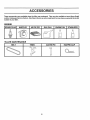
ACC
Rm
These accessories were available when the tiller was purchased. They are also available at most Sears Retail
outlets, Catalog and Service Centers. Most Sears Stores can order repair parts for you when you provide the model
number of your tiller.
ENGINE
SPARK
rpLUG
MUFFLER
AIR FILTER
GAS CAN
_L
TILLER
MAINTENANCE
BELT
TINES
CLEVIS PIN
0
5
HAIRPIN
CLIP
MBLY
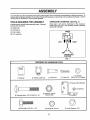
Your new tiller has been assembled at the factory with exception of those parts left unassembled for' shipping purposes, To
ensure safe and proper operation of your tiller' all parts and hardware you assemble must be tightened securely. Use the
correct tools as necessary to insure proper tightness°
TOOLS REQUIRED
FOR ASSEMBLY
OPERATOR'S
POSITION
(See Fig. 1)
When right or left hand is mentioned in this manual, it
means when you are in the operating position (standing
behind tiller handles),
A socket wrench set will make assembly easier,, Standard
wrench sizes are listed.
(1) Utility knife
(1) Screwdriver
FRONT
(I) Pair of pliers
(2) 1/2" wrenches
LEFT
RIGHT
OPERATOR'S
POSITION
FIG. 1
................
,
CONTENTS
,, ,,, ,, ,,,,,,,,,,,,,,..,,,...,,
OF HARDWARE
...........
I
I J
(1) Manual
I
I
II
I
lllj
PACK
J
LL
II
lUUlIIIlUlIIII
(1) Plastic Cable Clip
(1) Clevis Pin
Q
(2) Carriage Bolts 5/16-t8 UNC x 2-1/2
(1) Cotter Pin
(1) Reverse Rod Bracket
)
©
0
(1) Washer
9/32 x 1/2 x 14 Gauge
(_(1)
Bushing
I
(2) Flange Locknuts
5/16-18 UNC
Q
(2) Hex Bolts 5/16-18 x 1-1/4
,
(2) Hex Nuts 5/t6-18
,, ,,,,,,,,,
,,,,,,,,,,,,,,,
6
(2) Lock Washers 5/16
LY
UNPACK
i
A
CARTON
staples when handling or disposing of
CAUTION:
Be careful Of exposed
cartoning materia I,
TfNE CONTROL CABLE
!
a
!
TfNE CONTROL
HANDLE MOUNT
IMPORTANT:
WHEN UNPACKING AND ASSEMBLING
TILLER, BE CAREFUL NOT TO STRETCH OR KiNK
CABLE(S)
= Cut cable ties securing handle column.
=
°
o
COLUMN
Slowly lift handle column and lay it over tiller+
Remove packing from carton+, Hardware pack isfound
in folded cardboard packing.
Slide handle column onto handle mount,
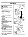
ASSEMBLE
HANDLE
(See Fig. 2)
o Slide reverse rod through hole in reverse rod bracket
as shown.
°
Slide bushing over lower reverse rod and snap into
bracket hole,+
•
Attach reverse rod bracket to handle column using two
(2) carriage bolts and two (2) flange tocknuts,,
NOTE: Make sure tine control cable is routed in front of
reverse rod bracket+
CABLE
CLII:
TtNECONTROLCABLE
=
Insert plastic cable clip into hole in handle column.,
o
Route tine control cable through plastic cable clip on
handle column.
o
Remove packing matedal from handle assembly+
°
Cut away carton.
=
Cut cable ties securing tiller to skid+ Remove tiller from
skid by pulling backwards+
\
UPPER
REVERSE
ROD
CARRIAGE
BOLTS
WASHER
PIN
ASSEMBLE
REVERSE
ROD (See Fig, 2)
o Secure upper reverse rod to lower reverse rod using
clevis pin, washer and cotter pin+
INSTALL
DEPTH STAKE ASSEMBLY
REVERSE
ROD
E
LOCKNUTS
LOWER
(See Fig. 3)
•
insert stake support between engine bracket halves
with stake spring down+,
FIG. 2
NOTE: It may be necessary to loosen nut "A",
•
Bolt stake support to engine brackets with botts, lock
washers and nuts. Tighten securely+ Also tighten nut
"A" if it was necessary to loosen.
ENGINE BRACKET
HALVES
°
Depth stake must move freely+ If it does not, toosen
support bolt.
HANDLE
HEIGHT
STAKE
SUPPORT
•
Handle height may be adjusted to better suit operator.,
(See "HANDLE HEIGHT'' in the Service and Adjustments section of this manual).
TILLING
WIDTH
•
DEPTH
STAKE
T+lling width may be adjusted to better handle your
tilling conditions (See "TINE ARRANGEMENT" in the
Service and Adjustments section of this manual)°
TINE OPERATION
=
SUPPORT BOLT
Check tine operation before first use+, (See "FINE
OPERATION CHECK" in the Service and Adjustments
section of this manual),,
HEX BOLTS,
LOCK WASHERS, AND HEX NUTS
FIG.
7
3
OPERATION
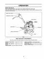
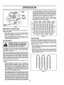
KNOW YOUR TILLER
READ THIS OWNER'S MANUAL AND SAFETY RULES BEFORE OPERATING YOUR TILLER.
Compare the illustrationswith your tiller to familiarize yourself with the location of various controls and adjustments, Save
this manual for' future reference.
REVERSE "ftNE CONTRO!.
FORWARD TINE CONTROL
CHOKECONTROL
THROTTLE
CONTROL
DEPTH STAKE
TINE SHIELD
RECOIL STARTER HANDLE
FIG. 4
MEETS ANSI SAFETY REQUIREMENTS
Sears tillers conform to the safety standards of the American National Standards Institute,.
FORWARD TINE CONTROL - Engages tines in forward
direction,
THROTTLE CONTROL - Controls engine speed.
DEPTH STAKE - Controls forward speed and the depth at
which the tiller' will dig_
RECOIL STARTER HANDLE - Used to start the engine,
REVERSE TINE CONTROL - Engages tines in reverse
direction,
CHOKE CONTROL - Used when starting a cold engine,.
8
OPEBATn
The operation of any tiller can result in foreign objects thrown into the eyes, which can
result in severe eye damage. Always wear safety glasses or eye shields before starting
your tiller and while tilling. We recommend a wide vision safety mask over the spectacles
or standard safety glasses.
TILLING
HOW TO USE YOUR TILLER
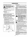
STOPPING
The speed and depth of tilling is regulated by the position
of the depth stake and wheel height.
(See Fig. 5)
TINES
•
Release forward tine control to stop forward movemento
=
Release reverse tine control to stop reverse movemento
The depth stake should always be below the wheets for
digging. It serves as a brake to slow the filler's forward
motion to enable the tines to penetrate the ground. Also,
the more the depth stake is lowered into the ground the
deeper the tines will dig.
DEPTH STAKE (See Fig. 6)
ENGINE
.
-
Adjust depth stake by removing the hairpin clip and clevis
pin,, Change depth stake to desired position° Replace the
clevis pin and hairpin clip,,
°
For normal tilling, set depth stake at the second or third
hole from the top.
Move throttle controt to "STOP" position,
Never use choke to stop engine.
REVERSE TINE CONTROL
FORWARD TINE CONTROL
WHEELS (See Fig. 6)
Adjust wheels by removing the hairpin clip and clevis pin°
Change wheel position_ Replace the hairpin clip and clevis
pin_
•
I
"
//./
/_
For normal tilling, set wheels at the second or third hole
from the top,,
HAIRPIN CLIP
AND CLEVIS PIN
FORWARD TINE CONTROL
"ON" (DOWN) POSITION
DEPTH
STAKE
CHOKE
CONTROL_,
HAtRPIN CL|P
AND CLEVIS PIN
WHEEL
FIG, 6
FIG. 5
TINE OPERATION
(See Fig. 5)
Start engine and move throttle control to desired speed..
FORWARD
•
Squeeze forward tine control to handle,,
REVERSE
•
With forward tine control in "OFF" (up) position, putt
back and hold reverse tine control,,
9
ii
OPERATION
TRANSPORTING
ADD GASOLINE
YOUR TILLER
•
Fitl fuel tank° Use fresh, c_ean, regular unleaded
gasoline_ (Use of leaded gasoline will increase carbon
and lead oxide deposits and reduce valve life.
IMPORTANT: WHEN OPERATING IN TEMPERATURES
BELOW 32°F, USE FRESH, CLEAN, WINTER GRADE
GASOLINE TO HELP INSURE GOOD COLD WEATHER
STARTING
CAUTION: Before lifting or transport,ing, allow tiller engine and muffler to
cool. Disconnectsparkplug wire. Drain
gasoline from fuel tank.
AROUND THE YARD
.
.
Tip depth stake forward until it is held by the stake
spdng.
Push tiller handles down, raising tines off the ground
•
Push or pull tiller to desired location°
WARNING: Experience indicates that alcohol blended
fuels (called gasohol or using ethanol or methanol) can
attract moisture which leads to separation and formation of
acids during storage, Acidic gas can damage the fuel
system of an engine while in storage. To avoid engine
problems, the fuel system should be emptied before storage of 30 days or longer'. Drain the gas tank, start the
engine and Iet it run until the fuel lines and carburetor are
empty. Use fresh fuel next season. See the Storage
section of this manual for'additional information. Never use
engine or carburetor cleaner products in the fuel tank or
_ermanent damage may occur,,
AROUND TOWN
°
•
Disconnect spark plug wire.
Drain fuet tank_
.
Transport in upright position to prevent oil leakage.
BEFORE
STARTING
ENGINE
IMPORTANT:
BE VERY CAREFUL NOT TO ALLOW
DIRT TO ENTER THE ENGINE WHEN CHECKING OR
ADDING OILOR FUEL. USE CLEAN OILAND FUELAND
STORE
IN
APPROVED,
CLEAN,
COVERED
CONTAINERS. USE CLEAN FILL FUNNELS.
A
CAUTION: Fill to within 1t2 inch of top
of fuel tank to prevent spills and to
allow for fuel expansion, If gasoline is
accidentally spilled, move machine
away from area of spill, Avoid creating
any source of ignition until gasoline
vapors have disappeared.
Do not overfill. Wipe off any spilled oil
or fuel. Do not store, spill or use gasoline near an open flame.
FILL ENGINE WITH OIL (See Fig. 7)
•
With engine level, remove engine oil filler plug.
°
Fill engine with oil to point of overflowing. For approximate capacity see "PRODUCT SPECIFICATIONS" on
page 3 of this manual°
Tilt tiller back on its wheels and then re-leveL
•
°
Check oil level. Refill to point of overflowingif necessaryo Replace oil filler plug_
.
For cold weather operation you should change oil for
easter starting (See OIL VISCOSITY CHART' Jnth
Customer Responsibilities section of this manual).
To change engine oil, see the Customer Responsibilities section of this manual.
°
i
iiii
iii
i
TO START ENGINE (See Fig. 8)
"OFF"
position
when
engine.in
CAUTION:
Keep
the starting
tine control
•
Make sure spark plug wire is properly connected.
•
Place throttle control in "FAST" position,
°
To start a coldengine; place choke controlin "CHOKE"
position. A warm engine requires less chokingto start_
•
Grasp starter handle with one hand and grasp the tiller
with other hand. Pull rope out slowly until engine
reaches start of compression cycle (rope will pult
slightly harder at this point)_
Pull starter handle quickly_ Do not let starter' handle
snap back against starter.
°
•
OIL
FILLER
PLUG
o
When engine starts, slowly move choke control to
"RUN" positionas engine warms up.
Move throttle controlto desired running position.
=
Allow engine to warm up for a few minutes before
engaging tines.,
NOTE: If at a high altitude (3000 feet) or in cold temperatures (below 32°F), the carburetor fuel mixture may need to
be adjusted for best engine performance, See 'q'O ADJUST CARBURETOR" in the Service and Adjustments
section of this manual
FIG. 7
NOTE: If engine does not start, see "TROUBLESHOOTING POINTS".
10
OPEBATmON
e
.---," CHOKE
CONTROL
THROTTLE
CONTROL
?
RECOIL STARTER /
HANDLE
You will find tilling much easier if you leave a row
untilled between passes., Then go back over the entire
area at right angles (See Fig ,.9),,There are two reasons
for doing this_ First, wide turns are much easier to
negotiate than about-faces,. Second, the tiller won't be
pulling itself, and you, toward the row next to iL
Set depth stake and wheel height for shallow tilling
when working extremely hard soil or sod,. Then work
across the first cuts at normal depth+
FIG. 8
BREAKING
IN YOUR TILLER
Break-in your belt(s), pulleys and tine control before you
actually begin ti_lingo
o
Start engine, tip tines off ground by pressing handles
down and engage tine control to start tine rotation.
Allow tines to rotate for five minutes..
•
Check tine operation and adjust if necessary. See
'q'tNE OPERATION CHECK" in the Service and Adjustments section of this manual..
TILLING
FIG, 9
CULTIVATING
Cultivating is destroying the weeds between rows to prevent them from robbing nourishment and moisture from
the plants+At the same time, breaking up the upper layer
of soiI crust will help retain moisture in the soil.. Best
digging depth is 1" to 3".
- You witl probably not need to use the depth stake.
Begin by tipping the depth stake forward until it is held
by the stake spring+
• Cultivate up and down the rows at a speed which will
allow tines to uproot weeds and leave the ground in
rough condition, promoting no further growth of weeds
and grass (See Fig,. t0).
HINTS
handling your tiller, start actual field
use with throttle in slow position (midCAUTION:
Until
you are
accustomed
way between
"FAST"
and
"IDLE"). to
l_
, ,
,,,,,,,,,,
,,,,,,,
,
To help tiller move forward, lift up the handles slightly (thus
lifting depth stake out of ground). To slow down the tiller,
press down on handles.,
If you are straining or tiller is shaking, the wheels and depth
stake are not set properly in the soil being tilled..The proper
setting of the wheels and depth stake is through trial and
error and depends upon the soil condition,. (The harder or
wetter the ground, the slower the engine and tine speed
needed+.Under these poorconditions, at fast speed the tiller
will run and jump over the ground),
A properly adjusted tiller will dig with little effort from the
operator.
°
Tilling is digging into, turning over, and breaking up
packed soil before planting° Loose, unpacked soil
helps root growth.. Best tilling depth is 4" to 6". A tiller
will also clear the soiI of unwanted vegetation.+ The
decomposition of this vegetable matter enriches the
soil+ Depending on the climate (rainfall and wind), it
may be advisable to till the soil at the end of the growing
season to further condition the soil.
FIG. 10
Soil conditions are importantfor proper tilling.+Tines will
not readily penetrate dry, hard soil which may contrib +
ute to excessive bounce and difficult handling of your
tiller.. Hard soil should be moistened before tilling;
however, extremely wet soil will "ball-up" or clump
during tilling,. Wait until the soil is less wet in order to
achieve the best results+When tilling in the fall, remove
vines and long grass to prevent them from wrapping
around the tine shaft and slowing your tiilingoperation,.
11
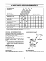
CUSTOMER
RESPONSIBILITIES
Jl,lll,l,lll
MAINTENANCE
ii II I Ill I
II
IIIIIIHIIIIll
Ill I I I I
I
/
SCHEDULE
FILL IN DATES
AS YOU COMPLETE
REGU_ R SERV ICE
Check Engine Oil Level
/
/Z_'-'/_/,
_b""
i _"--'/
V'
Change Engine Oil
K2
DATES
--'=-
V'
inspect Spark Ar rester Muffler
Inspect Air Screen
SERVICE
V'
I1_
Oil Pivot Points
_'_
V'
V'
Clean or Replace Air Cleaner Cartridge
!_ 2
Clean Engine Cylinder Fins
,,,
Replace Spark Plug
I_
.,,,,,
_,,
•
1 - Change more often when operating under a heavy load or in high ambient temperatures,
2 - Service more often when operating in dirty or dusty conditions
GENERAL
LUBRICATION
RECOMMENDATIONS
CHART
The warranty on this tiller does not cover items that have
been subjected to operator abuse or negligence_ To
receive full value from the warranty, operator must maintain tiller as instructed in this manual,
Some adjustments will need to be made periodically to
properly maintain your tiller°
** ENGINE
\
All adjustments in the Service and Adjustments section of
this manual should be checked at least once each
seasom
Once a year you should replace the spark plug, clean
or replace air filter, and check tines and belt for wear.
A new spark plug and clean air filter assure proper airfue! mixture and help your engine run better and last
Ionger_
BEFORE EACH USE
•
Check engine oil level.
•
•
Check tine operation,
Check for loose fasteners°
"IDLER
ARM
LUBRICATION
* SAE 30 OR 10W30 MOTOR OIL
** REFER TO CUSTOMER RESPONSIBILITIES
Keep unit welt lubricated (See "LUBRICATION CHART")
12
ENGINE
SECTION.
CUSTOMER
RESPONSIBmLUTNES
Disconnect spark plug wire before performingany maintenance(except carburetor adjustment) to prevent
accidental starting of engine,
Preventfires! Keep the enginefree of grass, leaves,spilledoil, or fuel. Removefuel from tank beforetipping
unit for maintenance. Clean mufflerarea of all grass, dirt, and debris.
Do not touch hot muffler or cylinderfins as contactmay cause burns,
.......
,llllllllll
llll
ill
ill1
ii
ii ii
ENGINE
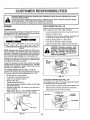
AIR CLEANER
U_e only high quality detergent oil rated with API service
classification SF or SG. Select the oil's SAE viscosity grade
according to your expected temperature
_'F
_20 _
"c -_o,
0_
.2'0.
TEMPERATURE
30 °
.I_,
32_
GRADES
40°
¥ .....
60 _
i'o,
80_
_o.
t00_
_o"
!
(See Fig. 13)
Service air cleaner cartridgeevery twenty-five hours, more
often if engine is used in very dusty conditions_
° Loosen air cleaner screws, one on each side of cover..
•
Remove air cleaner cover_
LUBRICATION
SAE VISCOSITY
I
i
I
I
4_"
°
Carefully remove air cleaner cartridge° Be careful. Do
not allow dirt or debris to fall into carburetor.
o
Clean by tapping gently on a fiat surface°
=
If very dirty or damaged, replace cartridge.
•
Clean and replace cover_Tighten screws securely°
RANGE ANT_CIPATED BEFORE NEXT OIL CHANGE
FIG. 1t
NOTE: Although multi-viscosity oils (5W-30,10W-30, etc.)
improve starting in cold weather, these multi-viscosity oils
will result in increased oil consumption when used above
32° F (0°C). Check your engine oil level more frequently to
avoid possible engine damage from running tow on oil,
Change the oil after the first two hours of operation and
every 25 hours thereafter or at least once a year if the tiller
is not used for 25 hours in one year
Check the crankcase oil level before starting the engine
and after each five (5) hours of continuous use Add SAE
30 motor oil or equivalent. Tighten oil filler plug securely
each time you check the oil level.
as kerosene, are not to be used to clean
cartridge, They may cause deterioration of the cartridge. Do not oil cartridge,
Do Petroleum
not use pressurized
to
CAUTION:
solvents, air
such
clean or dry cartridge.
!_
COVER
CLEANER
CARTRIDGE
TO CHANGE ENGINE OIL (See Figs. 11 and 12)
Determine temperature range expected before oilchange_.
All oil must meet API service classificationSF or SG..
.
o
•
•
°
.
.
•
Be sure tiller is on level surface
Oil will drain more freely when warm_
Catch oil in a suitable container.
Remove drain plug.
Tip tiller forward to drain oil
After oil has drained completely, replace oil drain plug
and tighten securely
Remove oil filler plugo Be carefut not to allow dirt to
enter the engine°
Refill engine with oil. See "CHECK ENGINE OIL
LEVEU' in the Operation section of this manual°
FIG. 13
COOLING
SYSTEM (See Fig. 14)
Your engine is air cooled For proper engine performance
and long life keep your engine clean°
•
Clean air screen frequently using a stiff-bristled brush,
-
Remove blower housing and clean as necessary,
-
Keep cylinder fins free of dirt and chaff.
MUFFLER
CYLINDER FINS
"_x
BLOWER
J
HOUSING
OIL
DRAIN
PLUG
AIR SCREEN
)
FIG. 14
PLUG
FIG. 12
13
CUSTOMER
Jill IIU
Ill/,llllUJlll
ILITI
,,
MU FFLER
TRANSMISSION
Do not operate tiller' without muffler° Do not tamper with
exhaust system. Damaged mufflers or spark arresters
could create a fire hazard° Inspect periodically and replace
if necessary, If your engine is equipped with a spark
arrester screen assembly, remove every 50 hours for
cleaning and inspection. Replace if damaged.
Your transmission issealed and will only require lubrication
if it is serviced.
CLEANING
•
•
Clean engine, wheels, finish, etc_.of all foreign matter°
Keep finished surfaces and wheels free of all gasoline,
oil, etc.
•
Protect painted surfaces with automotive type wax..
SPARK PLUG
Replace spark plugs at the beginning of each tillingseason
or'after every 50 hours of use, whichevercomes first. Spark
plug type and gap setting is shown in "PRODUCT SPECIFICATIONS" on page 3 of this manual,,
We do not recommend using a garden hose to clean your
unit unless the muffler, air filter and carburetor are covered
to keep water out. Water in engine c_nresult in a shortened
engine life_
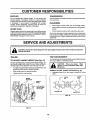
SERVICE AND ADJUSTMENTS
CAUTION: Disconnect spark plug wire from spark plug and place wire where it cannot come into
contact with plug.
TINEARRANGEMENT
TILLER
TO ADJUST
Your outer tines can be assembled in several different ways
to suit your tilling or cultivating needs_
HANDLE HEIGHT (See Fig. 15)
Factory assembly has provided lowest handle height. Select handle height best suited for your tilling conditions.,
Handle height will be different when tiller digs into soil..
•
°
If a higher handle height isdesired, loosen the four nuts
securing handle panel to engine brackets°
Slide handle panel to desired Iocation_
°
Tighten the four nuts securely.,
i_
gloves or other protection when hanCAUTION:
Wear
dling tines. Tines are sharp.
NORMAL TILLING -26 INCH PATH (See Fig. 16)
•
Assemble holes "A" in tine hubs to holes "B" in tine
shaft.
ENGINE
BRACKETS
HANDLE
PANEL
t
//
NUTS (ALSO 2
ON LEFT SIDE
OF TILLER)
iid
HAIRPIN CLIP
INNER TtNE
FIG. 16
FIG. 15
14
FINAL CHECK "ON" POSITION
MID-WIDTH TILLING - 24 INCH PATH (See Fig. 17)
,
Assemble holes "A" in tine hubs to holes "C" in tine
shaft.
/'-'1
o
o
Oll
Withtine control"ON"(held down tohandle) push down
on handte to raise tines off the ground.
•
Slowly pull recoil starter handle while observing tines,
Tines should rotate forward,
-
If tines do not rotate, inner wire of control cable is too
loose,. Loosen cable clip and pull cable up to remove
slack and retighten clip..
•
Recheck in "ON" position and adjust if necessary..
NOTE:, If "ON" position check required adjustment, recheck OFF position adjustment to insure tines do not
rotate when control is "OFF" (up).
FIG. 17
NARROW TILLINGtCULTIVATING
(See Fig, 18)
°
Remove outer tines°
=
- 12-314 INCH PATH
TINE CONTROL
t
II©i
©
©
TINE
"ON" CONTROL
POSITION
CABLE CLIP
TINE CONTROL CABLE
INNER TINES ONLY
FIG. 18
NOTE: When reassembting outer tines, be sure right tine
assembIy (marked "R") and left tine assembly (marked "L")
are mounted to correct side of tine shaft..
TINE OPERATION
i&
CHECK (See Fig. '19)
from spark plug to prevent starting
WARNING:
Disconnectsparkplugwire
...............i
while checking
tine operation,
For proper tine operation, forward tine control lever must be
against control body and all stack removed from inner wire
of control cable when control is in the "OFF" (up) position.
FIG, 19
If lever and cable are loose, loosen cabte clip at tower end
of cable° Pull up on cable to remove slack, without
extending spring on end of cable, and retighten cable clipo
FINAL CHECK "OFF" POSITION
°
With tine control "OFF" (up), push down on handle to
raise tines off the ground.
o
Slowly pull recoil starter handle while observing tines_
Tines should not rotate.
•
If tines rotate, inner wire of control cable is too tight
which is extending lower spring and engaging tines.
Loosen cable clip and push clown on cable only enough
to relieve spring tension_ Tighten cable clipo
Recheck in "OFF" position and adjust if necessary..
°
"OFF" POSITION
15
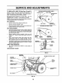
TO REPLACE V-BELTS (See Figs. 20 and 21)
FORWARDMOTION (INSIDE) V-BELT
ENGINE PULLEY
Replace V-belts if they have stretched considerably or if
they show cracks or frayed edges° There are two (2) Vbelts - forward (inside) and reverse (outside)°
t-
BELT GUIDE
TRANSMISSION
PULLEY
"
i
Belt guard must be removed to service belts, See "TO
REMOVE BELT GUARD" in this section of manual
NOTE: Observe carefully routing of both belts and location
of all belt guides before removing belts.
REVERSE
IDLER PULLEY
BELX REMOVAL
*
Remove reverse idler pulley from idler arm,
,
.
Remove reverse (outside) V-belt,
Remove forward (inside) V-beit from transmissionpulley first and then from engine pulley,
FORWARD
IDLER PULLEY
BELT GUIDE
REVERSE (OUTSIDE) V-BELT
BELT REPLACEMENT
•
Install new forward (inside) V-belt to engine pulley first
then to transmission pulley° Be sure belt is positioned
on inside groove of both pulleys, inside all belt guides
and rests on idler pulley.
•
Before installing reverse (outside) V-bett, turn belt
"inside out". Twist so wide, flat surface of belt is to
inside.
.
Wrap V-belt around reverse idler pulley and reassemble idler to idler arm. Tighten securely,, Be sure
belt is between reverse idler pulley and idler arm pin,
°
IDLER
PULLEY
ENGINE
PULLEY
FRONT
Install belt to outside groove of transmission pulley_Be
sure belt is inside all belt guides and rests on outside
groove of engine pulley_
IDLER PULLEY
VIEW
REFERENCE
REVERSE
CHECK TINE OPERATION
= See "FINE OPERATION CHECK" in this section of
manual.
IDLER
ARM PIN
--/
ENGINE
(_J
PULLEY
REPLACE BELT GUARD
FIG, 21
REVERSE
REVERSE (OUTSIDE) V-BELT
REVERSE
IDLER PULLEY
BELT
_RD
BOLT
IDLER
ARM
FOi
(INSIDE) V-BELT
ENGINE PULLEY
TRANSMISSION
PULLEY
FORWARD IDLER PULLEY
FIG. 20
16
SERVmCE AND ADJUSTMENTS
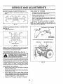
TO REMOVE
•
PRELIMINARY SETTING
BELT GUARD (See Fig. 22)
Remove two (2) cap nutsand washers from side of belt
guard_
Loosen (do not remove) tine shield nut on underside of
tine shield,.
•
•
•
Pull belt guard out and away from uniL
Replace belt guard by reversing above procedure° Be
sure slot in bottom of belt guard is under head of tine
shield bolt and all nuts are tightened securely.
*
Air cleaner assembly must be assembled to the carburetor when making carburetor adjustments°
o
With engine off, turn idle needle valve in (clockwise)
closingit finger tight and then turn valve out (counterclockwise) I-I/2 turns..
FINAL SETTING
•
°
CAP NUTS
_IDWASHERS
Start engine and allow to warm for five minutes_ Make
final adjustments with engine running at idle and tine
controliever in "OFF'' position°
Withthrottiecontrolin"SLOW"position, turn idleneedle
valve in (clock"wise)until engine begins to die then turn
out (counterclockWise)until engine runs rough° Turn
valve to a point midway between those two positions,.
IDLE RPM ADJUSTMENT
•
To adjust idle RPM, rotate throttle linkage counterclock,vise and hold against stop while adjusting idle
speed adjusting screw to obtain 1750 RPM. Release
throttle linkage.,
ACCELERATION
__-'_
°
BELT
\\
GUARD
High speed stop is factory adjusted
Do not adjust or
damage may result,
IMPORTANT:
NEVER TAMPER WITH THE ENGINE
GOVERNOR,
WHICH IS FACTORY SET FOR PROPER
ENGINE SPEED, OVERSPEEDING
THE ENGINE ABOVE
THE FACTORY
HIGH
SPEED
SETTING
CAN BE
DANGEROUS,, IFYOU THINKTHE ENGINE-GOVERNED
HIGH SPEED NEEDS ADJUSTING,
CONTACT YOUR
NEAREST SEARS SERVICE CENTER/DEPARTMENT,
WHICH HAS PROPER EQUIPMENT AND EXPERIENCE
TO MAKE ANY NECESSARY ADJUSTMENTS,
TINE SHIELD NUT
FIG. 22
ENGINE
TO ADJUST
CARBURETOR
TEST
Move throttle control lever from "SLOW" to "FAST"
position° If engine hesitates or dies, turn idle needle
valve out (counterclockwise) 1/8 turn, Repeattest
and
continue to adjust, if necessary, until engine acceter ates smoothly,,
(See Fig. 23)
The carburetor has a high speed fixed jet and has been
preset at the factory and adjustment shouId not be necessaryo However, minor adjustments may be required to
compensate for differences in fuel, temperature, altitude or
toad.. If the carburetor does need adjustment, proceed as
follows.,
THROTTLE LINKAGE
In general, turning the idle needle valve in (clockwise)
decreases the supply of fuel to the engine giving a leaner
fuel!air mixture.. Turning the needle valve out (counterclockwise) increases the supply of fuel to the engine giving
a richer fue!/air mixture°
IMPORTANT:
DAMAGE TO THE NEEDLES AND THE
SEATS IN CARBURETOR MAY RESULT IF SCREWS
ARE TURNED IN TOO TIGHT°
IDLE SPEED
ADJUSTING SCREW
THROTTLE
IDLE NEEDLE VALVE
FIG. 23
17
STOP
STORAGE
ENGINE OIL
Immediately prepare your tiiler for storage at the end of the
season or if the unit wilt not be used for 30 days or more.
Drain oil (with engine warm) and replace with clean oil,
(See "ENGINE" in the Customer Responsibilities section of
this manuaI)_
CAUTION: Never store the tiller with
gasoline in the tank inside a building
where fumes may reach an open flame
or spark. Allow the engine to coot
before storing in any enclosure.
CYLINDERS
•
Remove spark plug_
=
TILLER
Pour 1 ounce (29 ml) of oil through spark plug hole into
cylinder_
°
Pull starter handle slowly several times to distribute oil.,
°
Clean entire tiller' (See "CLEANING" in the Customer
Responsibilities section of this manual).
•
Replace with new spark plug.,
•
Inspect and replace belts, if necessary (See belt replacement instructions in the Service and Adjustments
section of this manual)_
OTHER
•
Do not store gasoline from one season to another_
•
Lubricate as shown in the Customer Responsibilities
section of this manual
•
Replace your gasoline can if your-can starts to rusL
Rust and/or dirt in your gasoline will cause problems.
°
Be sure that all nuts, bolts and screws are securely
fastened_ Inspect moving parts fordamage, breakage
and wear_ Replace if necessary_
•
°
Touch up all rusted or chipped paint surfaces; sand
lightly before painting,
i
llllll
JiJJiJJ
i
i i
If possible, store your unit indoors and cover it to give
protection from dust and dirt°
•
Cover your unit with a suitable protective cover that
does not retain moisture° Do not use plastic. Plastic
cannot breathe which allows condensation to form and
will cause your unit to rusL
IMPORTANT:
NEVER COVER TILLER WHILE ENGINE
AND EXHAUST AREAS ARE STILL WARM.
ENGINE
FUEL SYSTEM
IMPORTAN'i":
IT IS IMPORTANT TO PREVENT GUM
DEPOSITS
FROM FORMING
IN ESSENTIAL
FUEL
SYSTEM PARTS SUCH AS THE CARBURETOR,
FUEL
FILTER, FUEL HOSE, OR TANK DURING STORAGE°
ALSO,
EXPERIENCE
INDICATES
THAT ALCOHOL
BLENDED
FUELS
(CALLED
GASOHOL
OR USING
ETHANOL OR METHANOL) CAN ATTRACT MOISTURE
WHICH LEADS TO SEPARATION AND FORMATION OF
ACIDS DURING STORAGE. ACIDIC GAS CAN DAMAGE
THE FUEL SYSTEM OF AN ENGINE WHILE IN STORAGE
•
Drain the fuel tank._
•
Start the engine and let it run until the fuel lines and
carburetor are empty_
Never use engine or carburetor cleaner products in the
fuel tank or permanent damage may occur'.
Use fresh fuet next season.
.
°
NOTE: Fuel stabilizer is an acceptable alternative in
minimizing the formation of fuel gum deposits during storage., Add stabilizer to gasoline in fuel tank or storage
container° Always follow the mix ratio found on stabilizer
container. Run engine at least 10 minutes after adding
stabilizer to allow the stabilizer to reach the carburetor. Do
not drain the gas tank and carburetor if using fuel stabilizer
18
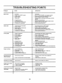
TROUBLESHOOTING
PROBLEM
POINTS
CAUSE
Will not start
Hard to start
, ,, ,,,,,,
,,, ,,,,,
!
2.
3
4,
5
Out of fuel
Engine not"CHOKED"
Engine flooded
Dirty air cleaner,
Water in fuel,
6.
7.,
8,
9,
Clogged fuel tank..
Loose spark plug wire.
Bad spark plug or improper gap
Carburetor out of adjustment.
6.
Fi]I fuel tank
See "TO START ENGINE in the Operation section
Wait several minutes before attempting to start
Clean or replace air clea.ner cartridge.,
Drain fuel tank and carburetor, and refill tank with fresh
gasoline
Remove fuel tank and clean.
7.
8.
9,
Make sure spark plug wire is seated properly on plug,,
Replace spark plug or adjust gap,
Make necessary adjustments,,
1,
2.
3
4o
5.
6.
Throttle control not set properly.
Dirty air cleaner,
Bad spark plug or improper gap.,
Stale or dirty fuel
Loose spark plug wire.
Carburetor out of adjustment.,
t.
2,
3
4
,,,,,,,,,,
Loss of power
CORRECTION
1,,
2_
3.
4.,
5,,
6,,
7,
8.
9
t0,,
11,,
12o
13,
I,
2.,
3.
4,,
5
properly,
Jir,
Place throttle control in "FAST" position
Clean or replace air cleaner cartridge.
Replace spark plug or adjust gap,
Drain fuel tank and refill with fresh gasoline,
5
Make sure spark ptug wire Is seated properly on plug
6, Make necessary adjustments,
,.Ir,L,,L,
Engine is overloaded.
Dkty air cleaner.
Low oil level/dirty oil.
Faulty spark plug.
Oil In fuel
Stale or dirty fuel.
Water in fuel,.
!, Set depth stake and wheels for shallower tiliingo
2, Clean or replace air cleaner cartridge_
3, Check ofl leveVchange oil
4, Clean and regap or change spark plug,
5 Drain and clean fuel tank and refill, and clean carburetor
6 Drain fuel tank and refill with fresh gasoline
7 Drain fuel tank and carburetor, and refill tank with fresh
gasoline,
8, Remove fuel tank and clean,
9. Connect and tighten spark plug wire.
10. Clean engine air screen
11. Clean/replace muffler,
12 Make necessary adjustments
13., Contact an authorized Sears Service CentedDepartment,
Clogged fuel tank,
Spark plug wire loose°
Dirty engine air screen..
Dtrty!c_ogged muffler.
Carburetor out of adjustment.,
Poor compression,
i
t
2,
3.
4,
5.,
Check oil leveltchange off
Clean engine air screen.
Clean cylinder fins, air screen, muffler area
Remove and clean muffler.,
Adjust carburetor to richer position,
1, Ground too dry and hard.
!.
2,
2,
Moisten ground or walt for more favorable soil
conditions
Adjust wheels and depth stake,
Engine overheats
1.
2_
3,
4,
5,
Excessive bounce!
Low otl ]svelldirty oil,
Dirty engine air screen,
Dirty engine
Partially plugged muffler,
improper carburetor adjustment,
difficult handling
Soil bails up or clumps
Wheels and depth stake incorrectlyadjusted
1_ Ground too wet
I.. Walt for more favorable soil conditions
1.. Tins control is not engaged.
2, V-belt not correctly adjusted
3,, V-belt is off pulley(s),
1- Engage line control.
2. Inspect/adjust V-beff,
3 Inspect V-belt
IU
Engine runs but tiller
won't move
i
i
i
i!l
Engine runs but labors
when tilling
i/
/iJ LIIJJILIJJJJIll
1, Set depth stake for shallower tilling
2. Check throttle control setting,,
3 Make necessary adjustments,
t., Tilling too deep,
2, Throttle control not properly adiusted.
3, Carburetor out of adjustment..
19
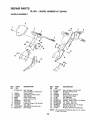
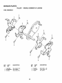
REPAIR PARTS
TILLER - - MODEL NUMBER 917.295450
HANDLE ASSEMBLY
2
3
25
4
16
5
8
17
18
13
12
KEY
NO.
PART
NO.
1
STD533125
2
3
4
5
6
7
8
9
t0
11
t2
136993
110512X
110632X
3066J
2635J
12000027
23200405
73970500
121t45X
110514X500
98000129
DESCRIPTION
KEY
NO.
t3
14
t5
16
17
18
t9
20
2t
22
23
24
25
Bolt, Carriage
5/16-18 UNC x 2-3/8 Grade 5
Panel, Control
Assembly, Handle Column
Grip, Handle
Cable, Tine Control
Lever, Control, Tine
Ring, Clip
Screw, Set
Locknut, Flange 5/16-18 UNC
Clip, Cable
Assembly, Panel and Tube
Nut, Flange
PART
NO.
STD533t07
136998
139907
106932X
101248K
1778E
137056
STD551037
STD561210
STD560907
19090814
72010520
137640
NOTE:
20
DESCRIPTION
Bolt, Carriage 5116-18 x 3/4
Bracket, Reverse Rod
Grommet
Knob, Control, Reverse
Reverse Rod, Upper
Pin, Retaining
Reverse Rod, Lower
Washer 13/32 x 13/16 x t 6 Gauge
Pin, Cotter 1/8 x 3/4
Pin, Cotter 3132 x 1/2
Washer 9/32 x 1/2 x 14 Gauge
Bolt 5/16-18 x 2-1/2
Bushing, Reverse Rod Bracket
All component dimensions given in U,.S. inches.
1 inch = 25,.4 mm
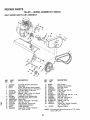
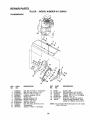
REPAmRPARTS
TILLER
-- MODEL
NUMBER
917.295450
BELT GUARD AND PULLEY ASSEMBLY
\
4
\
29
7
_/;:_
10
11
12
9
26
20
25
17
24
23
18
21
KEY
NO,
1
2
3
4
5
6
7
8
9
10
11
12
13
14
15
16
PART
NO,
!23643X
9484R
86777
74770812
STD541037
19131316
2009J
t27180X
74760628
106970X459
STD551025
t04213X
721404O5
133035
2614J
23230506
DESCRIPTION
KEY
NO.
PART
NO.
Assembly, Bracket, Belt Guard
Clip, Cable
Screw, Hex Washer Head, Slotted,
Thread Cutting #10-24 x 1/2 Type D
Bolt, Hex Head 1/2-20 x 3/4
Nut, Hex 3/8-16
Washer 13/32 x 13/16 x 16 Gauge
Pulley, Idler, Reverse
Assembly, Arm, Reverse Idler
Bolt, Hex Head 3/8-16 x 1-3/4
Guard, Belt
Washer 9/32 x 5/8 x t6 Gauge
Nut, Cap 1/4- 20
Bolt, Carriage 1/4-20 x 5/8
V-Belt (Forward Motion)
V-Belt (Reverse)
Screw, Set, Socket, Headless
C.P, 5/16-18 x 3/8
17
18
19
20
21
22
23
24
25
26
27
28
29
30
2649M
2607J
110550X
12000036
STD541237
9178R
674A30
STD523712
106968X
73350500
STD541025
STD551125
109227X
23200404
31
101189L
NOTE:
21
DESCRIPTION
Key, Square
Sheave, Transmission
Bolt, Belt Guard
Ring, Klip
Nut, Hex, Jam 3/8-16
Pulley, Id[er
Arm, IdEer
Bolt, Hex Head 3/8-16x 1-1/4
Shaft, IdlerArm
Nut, Hex, Jam 5/16-18
Nut, Hex 1/4-20
Washer, Lock 1/4
Pad, Idler
Screw, Set, Socket, Headless
C..Po 1/4-20 x 1/4
Sheave, Engine
Al! component dimensions given in U.S.. inches.
1 inch = 25.4 mm
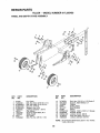
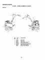
REPAIR PARTS
TILLER--
MODEL
NUMBER
917.295450
WHEEL AND DEPTH STAKE ASSEMBLY
7
22
.d
/
17
<,
19 20
20 19
_"
18
16
17
KEY
NO,
PART
NO.
1
2
3
4
5
6
7
8
9
10
11
9194R
74760520
STD523107
8TD541031
STD551131
73800600
4921H
1952J5O0
122233X
326J
74780628
DESCRIPTION
KEY
NO.
Pin, Clevis
Bolt, Hex Head 5!16-18 x 1-1/4
Bolt, Hex Head 5/16-18 x 314
Nut, Hex 5/16-18
Washer, Lock 5/16
Locknut, v#washer 3/8-16
Clip, Hairpin
Support, Depth Stake, R,H.
Stake, Depth
Pin, Clevis
Bolt, Fin, Hex 3/8-16 x 1-3/4
12
13
14
15
16
7
18
19
20
21
22
PART
NO.
74760524
1951J500
120958X
5388J
121117X
9188R
STD551037
9190R500
STD541437
74760516
73800500
NOTE:
22
DESCRIPTION
Boit, Hex 5116-18 x 1-1t2 Grade 2
Support, Depth Stake, L.H..
Washer
Spring, Stake
Bolt, Shoulder
Wheel
Washer 13/32 x 13/16 x 1I Gauge
Bracket, Wheel
Locknut, Crown 3/8-16
Bolt, Hex Head 5/16-18 x t
Locknut, w/insert 5/16-18
All component dimensions given in U.S inches°
1 inch = 25.4 mm
REPAIR PARTS
TILLER
-- MODEL
NUMBER
917.295450
TINE ASSEMBLY
2
6
6
i
6
KEY
NO,
PART
NO.
1
2
3
100746M
STD624008
674A43
DESCRIPTION
KEY
NO.
Tine, Outer, R.H.
Clip, Hairpin
Tine, Inner, R.H.
4
5
6
23
PART
NO.
674A42
100744M
4929H
DESCRIPTION
Tine, Inner, L.H.
Tine, Outer, L.H.
Pin, Clevis
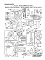
REPAIR PARTS
TILLER - - MODEL NUMBER 917.295450
TRANSMISSION
2O
3
3
7
14
14
10
14
15
11
12
KEY
NO.
PAR'('
NO.
1
2
3
5
6
7
8
9
10
11
12
13
74760524
74780652
STD551037
73800600
9057R459
1949J500
110519X500
STD551131
STD541031
74760544
126669X
19171616
DESCRIPTION
Bolt, Hex 5/16-18 x 1-1/2 Grade 2
Bolt, Fin, Hex 3/8-16 x 3-1/4
Washer 13/32 x 13/16 x 11
Locknut, w/washer 3/8-16
Shield, Tine
Bracket, Engine, R_H.
Bracket, Engine, L.H.
Washer, Lock 5/16
Nut, Hex 5/16-18
Bolt, Hex Head 5/16-18 x 2-3/4
Transm{ssion
Washer 17/32 x 1 x 16 Gauge
KEY
NO.
PART
NO.
14
15
16
17
18
19
20
9173R
STD541431
19091412
19092016
STD551 I25
74610412
146151
DESCRIPTION
Spacer, Split
Nut, Hex, Keps 5/16-18 UNC
Washer 9/32 x 7/8 x 12 Gauge
Washer 9/32 x 1-1/4 x 16 Gauge
Washer', Lock 1/4
Bolt, Hex 1/4-28 x 3/4 Grade 5
Engine, Briggs & Stratton, 5 HP,
Model No= 133202, Type 0156-01
NOTE: All component dimensions given in U_S, inche&
1 inch = 25.4 mm
24
REPAIR PARTS
TILLER
- - MODEL
NUMBER
917.295450
DECALS
5
2
KEY
NO.
1
2
3
4
5
6
8
---
PART
NO.
141169
133026
137737
137653
I20431X
110719X
120075X
146331
146332
DESCRIPTION
Decal, Logo
Decal, Logo
Decal, Logo
Decal, Caution, Tine Control
Decal, Hand Placement
Decal, Operation and Lubrication
Decal, Warning, Rotating Tines
Manual, Owner's(English)
Manual, Owner's(Spanish)
25
REPAIR PARTS
TILLER
BRIGGS
& STRATTON
- - MODEL
ENGINE
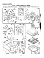
NUMBER
-- MODEL
917.295450
NUMBER
133202,
TYPE
NO. 0156-01
1019
LABEL
KIT
36 35
306
1058
OWNER'S
_
4o
552
741
tl
15
llll
ill
W
i
613
26
81
978
22
INSTRUCTION MANUAL,
26
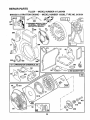
RE!PARRPARTS
TILLER -- MODEL NUMBER 917.295450
BRIGGS
& STRATTON
ENGINE
- - MODEL
NUMBER
133202,
TYPE
NO. 0156-01
97
634
_
_202
203
205
127
153
__
995
414
542
190A
202A__
_" o__19o_
209
153
.....................
°
967
191
916
181
621
224
2O4
223
526
27
REPAIR PARTS
TILLER
BRIGGS
& STRATTON
- - MODEL
ENGINE
NUMBER
- - MODEL
917.295450
NUMBER
133202,
TYPE
NO. 0156-01
3°°
_r REQUIRES SPECIAL TOOLS
TO INSTALL SEE REPAIR
INSTRUCTION MANUAL,
334
73
23'
24
O
200
52
9
3O7
7
332
455
3
121 CARBURETOR OVERHAUL KIT
163
(_
191
J3S8
Q_SKET
SE'T
163
1016
461
69A
515
58
69
28
456
REPAIR PARTS
TILLER
BRIGGS
KEY PART
NO. NO,
t
2
3
5
7
8
9
10
11
t2
13
14
15
16
18
19
20
2t
22
23
24
25
26
27
28
29
30
32
33
34
35
36
37
395990
297565
2998't9
214040
272157
495774
27549
94621
66578
270080
270125
270126
94221
94679
93448
94387
492088
230978
2976O2
495660
294606
66768
94682
297229
222698
298904
298905
298906
298907
298982
299742
298983
298984
298985
26026
298909
298908
299430
390459
221890
94745
211119
261044
260552
26478
222443
& STRATTON
-- MODEL
ENGINE
NUMBER
- - MODEL
917.295450
NUMBER
KEY PART
NO. NO.
DESCRIPTION
'133202, TYPE
NO. 0156-01
DESCRIPTION
Retainer, intake Valve and Exhaust
Spring
45 260642 _
-Tappet, Valve--.
Gear, Cam
46 212733
52 271936
*** Gasket, Carburetor Mounting (2)
55 494846
Housing, Rewind Starter
56 493824
Pulley, Rewind Starter
57 262594
Spring, Rewind Starter
58 280406
Rope, Rewind Starter
(Cut to Required Length)
59 396892
Insert, Starter Handle
60 393152
Handle, Rewind Starter
65 94686
Screw, Housing Mounting
Washer
69 280973
Washer
69A 224322
73 224632
Screen, Rotating
81 222263
Lock, Screw
90 495426
Carburetor Assembly
Screw, Throttle Valve to Shaft
95 93499
Throttle, Carburetor
96 223793
97 490048
Shaft and Lever, Throttle
108 491177
Valve and Shaft Group, Choke
118 231533
Valve, Needle
Carburetor Overhaul Kit
121 495606
124 94616
Screw, Hex Head
127 220352
Plug, Welch
127A 223789
Plug, Welch
149 26336
Spring, Needle Valve
152 260575
Spring, Throttle Adjustment
Screw and Collar
t53 490589
Screw, Machine, Round Head
154 93527
163 271935
* Gasket, Air Cleaner Mounting
180 495405
Tank Assembly, Fuel
181 494559
Cap, Fuel Tank
190 94712
Screw, Fuel Tank
190A 94677
Screw, Fuel Tank Mounting 1_3/4"
191 272489
*** Gasket, Fuel Tank to Carburetor
Guide, Air
200 223886
202 262270
Link, Throttle
Bell Crank
203 280720
Cylinder Assembly
Bushing, Cylinder
*Seal, Oil _
Head, Cylinder
* Gasket, Cylinder Head
Breather Assembly
* Gasket, Valve Cover
Screw, Breather Mounting
Grommet, Breather Tube
* Gasket, Crankcase, Standard o0t5"
* Gasket, Crankcase °005" Thick
* Gasket, Crankcase .009" Thick
Screw, Cylinder Head 2-3/32"
Screw, Cylinder Head 2-15132"
Plug, Pipe, Hex Socket
Plug, Oil Drain
Crankshaft
Gear Pin, Crankshaft
Cover Assembly, Crankcase
Bushing, Crankcase Cover
* Seat, Oil
Plug, Oil Filler
Screw, Cover Mounting
Flywheel, Magneto
Key, Flywheel
Piston Assembly, Standard Size
Piston Assembly .010" Oversize
Piston Assembly .020" Oversize
Piston Assembly .030" Oversize
Ring Set, Piston, Standard Size
Ring Set, Piston, Standard, Chrome
Ring Set, Piston .010" Oversize
Ring Set, Piston .020" Oversize
Ring Set, Piston .O30" Oversize
Lock, Piston Pin
Pin Assembly, Piston, Standard
Pin Assembly, Piston .005" Over
Rod Assembly, Connecting
Rod Assembly, Connecting
.020" Undersize Crankpin Bore
Dipper, Connecting Rod
Screw, Connecting Rod
Valve, Exhaust
Valve, intake
Spring, intake Valve
Spring, Exhaust Valve
Guard, Flywheel
40
93312
*
**
***
Included in Gasket Set (495603)
included in Carburetor Overhaul Kit (495606)
Included in both Gasket Set (495603), and
Carburetor Overhaul Kit (495606)
NOTE: All component dimensions given in UoS°inches
1 inch = 25°4 mm
29
REPAIR PARTS
TILLER
BRIGGS
KEY PART
NO. NO.
204
205
208
209
216
219
220
222
223
224
222962
231520
262279
262283
262359
494845
221551
490649
223455
93491
227
230
256
257
300
304
305
306
307
308
332
333
334
337
346
356
358
363
373
383
392
394
414
432
433
434
435
455
456
459
461
467
515
526
527
490374
222450
223813
93543
393615
495759
94619
221511
94680
224738
92284
397358
93414
802592
93705
398808
495603
19069
92987
89838
262328
272538
220982
221377
93265
214021
93141
224250
224321
492833
262626
280715
262625
94659
223786
& STRATTON
- - MODEL
ENGINE
NUMBER
- - MODEL
917.295450
NUMBER
133202,
KEY PART
NO. NO.
DESCRIPTION
Bushing, Governor Lever, Flat
Screw, Shoulder
Rod, Speed Control
Spring, Governor
Link, Choke
Gear, Governor
Washer, Thrust
Panel, Control
Lever, Governor Control
Rivet, Governor Control Lever
Mounting
Lever Assembly, Governor
Washer, Governor Lever
Crank, Bell
Screw, Sems, Hex Head
Muffler, Exhaust
Housing, Blower
Screw, Blower Housing Mounting
Shield, Cylinder
Screw, Cylinder Shield
Cover, Cylinder Head
Nut, Flywheet
Armature Group
Screw, Armature Mounting
Plug, Spark
Screw, Seres
Wire, Ground
Gasket Set
Flywheel Puller
Nut, Hex
Wrench, Spark Plug
Spring, Fuel Pump Diaphragm
** Diaphragm
Washer
Cap, Spring
Pin, Diaphragm Cover
Cover, Diaphragm
Screw, Diaphragm Cover
Cup, Starter
Retainer
Pawl, Starter
Pin, Spring
Knob, Control
Spring
Screw, Sems, Tank Bracket Mount.
Clamp, Breather-Tube
528
529
542
552
562
592
608
611
613
614
615
6t6
621
634
635
676
679
680
741
779
851
869
870
871
231550
67838
93572
231079
92613
231082
495766
391813
93935
93306
93307
231077
396847
271853
66538
393757
270382
221839
261696
262570
221798
211787
21!172
262001
63709
916 280321
966 492797
967 491588
968 495357
969 490073
971 94018
987 398970
995 223887
1012 490507
1016 224278
RPM Settings:
*
**
***
Included in
Included in
Included in
Carburetor
TYPE
NO. 0156-01
DESCRIPTION
Tube, Breather
Grommet, Breather Tube
Screw
Bushing, Governer Crank
Bolt, Governor Lever
Nut, Hex
Starter Assembly, Rewind
Fuel Pipe and Clip Assembly
Screw, Hex Head, Shoulder
Pin, Cotter'
Retainer, E-Ring
Crank, Governor
Switch, Stop
Washer', Throttle Shaft, Foam
Elbow, Spark Plug
Deflector, Exhaust, Side Outlet
Washer, Foam
Washer, Brass
Gear, Timing
Link, Speed Control
Cable Terminal, ignition
Seat, Intake Valve, Standard
Seat, Exhaust Valve, Standard
Guide, Exhaust Valve
Guide, Intake Valve
Rack, Gear Control
Base, Air Cleaner
Filter, Air Cleaner
Cover, Air Cleaner
Screw, Air Cleaner
Screw, Hex Head
Seal, Throttle Shaft
Lever, Bracket Assembly
Retainer, Link
Spacer
Low Speed: 1750-1950
High Speed: 3400-3600
Gasket Set (495603)
Carburetor Overhaul Kit (495606)
both Gasket Set (495603), and
Overhaul Kit (495606)
NOTE: All component dimensions given in U.So inches
1 inch = 25_4 mm
3O
NOTES
SERV
31
OWNER'S
MANUAL
MODEL NO.
917.295450
1:1111
MAIl +
5.0 HP
26 INCH TINE WIDTH
FRONT TINE TILLER
WITH REVERSE
Each tiller has its own model number'+ Each engine has its own model
number.
The model number for' your tiller will be found on a plate attached to the
right hand engine bracket,.
The model number for your engine will be found on the blower housing of
the engine,,
IF YOU NEED
REPAIR SERVICE
OR PARTS:
FOR REPAIR SERVICE, CALL
THIS TOLL FREE NUMBER:
1-800-4-REPAIR
(1-800-473-7247)
FOR REPLACEMENT PARTS
INFORMATION AND
ORDERING, CALL THIS
TOLL FREE NUMBER:
1-800-FON-PART
(1+800+366-7278)
All parts listed herein may be ordered from any Sears, Roebuck and Co+
Service Center/Department and most Retail Stores,,
WHEN ORDERING REPAIR PARTS, ALWAYS GIVE THE FOLLOWING INFORMATION:
• PRODUCT - FRONT TINE TILLER
• MODEL NUMBER - 917.295450
- ENGINE MODEL NUMBER - 133202, TYPE NUMBER 0156-01
• PART NUMBER
,, PART DESCRIPTION
Your Sears merchandise has added value when you consider Sears has
service units nationwide staffed with Sears trained technicians+++ professional technicians specifically trained to insure that we meet our pledge
to you, we service what we sell,,
Sears, Roebuck and Co., Hoffman Estates, IL 60179 U.S.A.
146331
t2+16+94
PRINTED IN THE U.S+A+