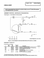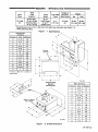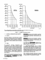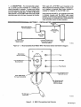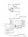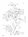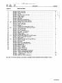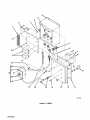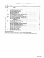
1
October 1985
Read
IMPORTANT
and
understand
the
entire
Effective With Serial No. JF.22
_____________
contents of both this manual and the power source
manual used with this unit, with special emphasis
throughout both manuals,
installing, peratlng, or maintaining this
equipment. This unit and these instructions are for
use only by persons trained and experienced in the
safe operation of welding equipment. Do not allow
on
FORM: OM-1096A
the safety material
before
untrained persons to install, operate, or maintain
this unit. Contact your dIstributor If you do not fully
understand these instructions.
OWN ERS
MANUAL
MODEL
MOTORIZED SLIDE
MOTORIZED SLIDE CONTROL
MSC-2
rnIHEii
MILLER ELECTRIC MFG. CO.
718 S. BOUNDS ST. P.O. Box 1079
APPLETON, WI 54912 USA
ADDITIONAL COPY PRICE 50 CENTS
NWSA CODE NO. 4579
PRINTED IN U.S.A.
.~
LIMITED WARRANTY
EFFECTIVE: FEBRUARY 25, 1985
This warranty supersedes all previous MILLER warranties and is ox
clusive with no other guarantees or warranties expressed or implied.
LIMITED WARRANTY
tions hereof,
4
-
Miller Electric
warrants to its
Subject to the terms
Mfg. Co., Appleton,
Distributor/Dealer that all
new
and condiWisconsin
and unused
q~
Equipment furnished by Miller is free from defect in workmanship and material as of the time and place of delivery by Miller.
No warranty is made by Miller with respect to engines, trade
accessories or other items manufactured by others. Such
engines, trade accessories and other items are sold subject to
A)l
the warranties of their respective manufacturers, if any
engines are warranted by their manufacturer for one year from
date of original purchase, except Tecumseh engines which
~
have
~
~
.
a two
year warranty.
as specified below, Millers warranty does not apply
components having normal useful life of less than one (1)
year, such as spot welder tips, relay and contactor points,
MILLERMATIC parts that come in contact with the welding
Except
In the case of Millers breach of warranty or any other duty
with respect to the quality of any goods, the exclusive remedies
therefore shall be, at Millers option (1) repair or (2) replacement
or, where authorized in
the reasonable cost of
writing by Miller in appropriate cases, (3)
repair or replacement at an authorized
Miller service station
(4) payment of
or
pnce (less reasonable
or
credit for the
I
~
~.!
~
purchase
depreciation based
upon actual use) upon
risk and expense. MILLERs
the goods at Customers
option of repair or replacement will be FOB., Factory, at
Appleton, Waconsin, or F.O.B., at a MILLER authorized service
facility, therefore, no compensation for transportation costs of
any kind will be allowed. Upon receipt of notice of apparent
defect or failure, Miller shall instruct the claimant on the warranty
claim procedures to be followed.
return of
i~
~
~.
to
~
~
wire including nozzles and nozzle insulators where failure does
not result from defect in workmanship or material.
ANY EXPRESS WARRANTY NOT PROVIDED HEREIN AND
ANY IMPLIED WARRANTY, GUARANTY OR REPRESENTA
TION AS TO PERFORMANCE, AND ANY REMEDY FOR
BREACH OF CONTRACT WHICH, BUT FOR THIS PROVISION,
required to honor warranty claims on warEquipment in the event of failure resulting from a defect
within the following periods from the date of delivery of Equipment to the original user:
ARISE BY IMPLICATION, OPERATION OF LAW.
CUSTOM OF TRADE OR COURSE OF DEALING, INCLUDING
ANY IMPLIED WARRANTY OF MERCHANTABILITY OR OF
FITNESS FOR PARTICULAR PURPOSE, WITH RESPECT TO
Miller shall be
~
~
~
ranted
MIGHT
~
~.
~
ANY AND ALL EQUIPMENT FURNISHED BY MILLER IS EX
Arc welders, power sources and components
2. Original main power rectifiers
1.
r~
(labor
3.
-
1 year
....
1 year
only)
Allweldingguns,feeder/gunsandplasmatorches... 90days
4. All other Millermatic Feeders
5.
Replacement
6.
Batteries
or
repair parts, exclusive
of labor
..
1 year
60 days
6 months
4
provided that Miller is notified
in
writing
within
thirty (30) days
of the date of such failure.
r~
~
.
submitted by the
~
~
ori~nal
~
user
.
wittun the
~
CLUDED AND DISCLAIMED BY MILLER.
3 years
ji
.
foregoing periods
~,
~
~
EXCEPT
AS
EXPRESSLY PROVIDED BY MILLER IN
INTENDED
ARE
PRODUCTS
FOR
ULTIMATE
PURCHASE BY COMMERCIAL/INDUSTRIAL
USERS AND FOR OPERATION BY PERSONS TRAINED AND
EXPERIENCED
THE
AND
IN
USE
MAINTENANCE
OF
WELDING EQUIPMENT AND NOT FOR CONSUMERS OR
CONSUMER USE. MILLERS WARRANTIES DO NOT EXTEND
TO, AND NO RESELLER IS AUTHORIZED TO EXTEND
MILLERS WARRANTIES TO, ANY CONSUMER.
WRITING,
~
MILLER
~
~
J~
~
?
~
ERRATA SHEET
r
After this manual was
to data
appearing
printed, refinements
AMENDMENT TO SECTION 4
Amend
Figure
In
equipment design occurred. This sheet lists exceptions
later In this manual.
4-1. Circuit
MAINTENANCE & TROUBLESHOOTING
Diagram
For Motorized Slide
RC I
RED
C
(CW)
LS I
Cl
A
B
D
147
A
B
C
0
ITO
0
0
0
505
Figure
504
502
4-1. Circuit
Circuit Diagram No. SA-1 23 536
50/
Diagram
For Motorized Slide Effective With Serial No. JJ494608
AMENDMENT TO PARTS LIST
Amend Parts List as follows:
Dia.
Part
No.
Mkgs.
Replaced
**
.
2-16
.
2-19
2-20
.
2-21
.
.
2-22
.
.
..
.C1
.
.
.
Description
With
059712... .059712.
090637... .148315.
090634... .148316.
007 532..
Deleted.
.089475... .148317.
.
.
.
.
.
.
CLIP, (qty chg
w/KB107753)
BRACKET, mtg resistor/capacitor (Eff w/KB107753)
DOOR, access (Elf w/KB1 07753)
Efl
Elf w/KB1 07753
CAPACITOR, polye met film 7.5uf 250 VAC
(Elf w/KB107753)
4-20
**Fjrst
090117..
107 623..
SWITCH, job stick (Eff w/JG026925)
digit represents page no digits following dash represent item no.
BE SURE TO PROVIDE MODEL AND SERIAL NUMBER WHEN ORDERING REPLACEMENT PARTS.
-
Quantity
.3
TABLE OF CONTENTS
Page No.
Section No.
SECTION 1
1
1
1
-
-
-
INTRODUCTION
-
1.
General Information And Safety
2
2.
Receiving-Handling
Description
2
3.
SECTION 2
-
3
INSTALLATION
2-1.
Location
4
2
2.
Interconnecting Cord Installation From Motorized Slide To MSC-2
4
3.
Electrical Connection From An Automatic Device (Weld Control)
To The MSC-2
4
4.
6.
Electrical Input Connection For MSC-2
Electrical Connection To Motorized Slide With System 9
Optional Motorized Slide Control With System 9 Connections
7.
Gun
2
2
2
2
2
-
-
-
-
-
-
5.
SECTION 3
3
3
-
-
-
Limit Switch
Limit Switch (Customer
SECTION 4
4
-
1.
6
Supplied)
MSC-2
Motorized Slide Control (Joystick; Standard On MSC-2 And
Optional With The SYSTEM 9)
-
6
OPERATOR CONTROLS
1.
4.
5
6
Plate
2.
3-3.
3
-
Mounting
4
6
7
7
MAINTENANCE & TROUBLESHOOTING
Interconnecting Cords
7
4-2.
Slide
7
4
Drive Belt
7
4.
Fuse Protection
8
5.
Troubleshooting Chart
8
4
4
-
-
-
3.
SEeBONt
INTRODUCTION
-
Slide
Voltage At
Input
Load
Travel
Power
Capacity*
Speed
Vertical Mtg.
115 Volts
AC
18
-
75 lbs. (34 kg)
Horizontal Mtg.
74 lbs. (33 kg)
Slide Control
Net
Ship
5 in.
24 Volts
(127 mm)
AC
32 lbs.
(14.5 kg)
45 lbs.
(20.4 kg)
Motorized
ipm
(0.457 mpm)
-
eig ht
Total Slide
Travel
27
ipm**
(0.686 mpm)
*Capacities given are at 12 in. (305 mm) from slide
pulleys.
cover
face plate (see
Figure 1-3).
**With optional
Figure 1
-
1.
Specifications
Motorized Slide
Dimensions
Dimension
Inches
Millimeters
A
5-1/16
129
B
4-1/4
108
C
5
127
0
12-7/8
327
E
13/32
10
F
5/8
16
G
14
356
H
11-3/16
284
J
9-3/16
233
K
5/8
16
L
9-3/8
238
M
8-1/8
206
N
5-19/32
142
P
1
25
14-3/8
mounting
in.
(365
mm)
to
bottom
of
feet.
TC-091 229
Motorized Slide
MSC-2 Dimensions
Base Pan
Mounting
Feet
Dimension
a
1
-
Millimeters
A
2-7/8
73
B
1-7/16
37
C
1/4
6
D
4-11/16
119
E
5-1/4
133
F
4-1/2
114
G
2
51
H
5-1/4
133
J
9
229
K
9-1/2
241
L
8-3/4
222
M
3/8
10
N
8
203
P
5
127
Q
1-1/2
38
TC-106 544
Figure
Inches
2. Overall Dimensions
OM-1096
Page
1
DISTANCE
48 In.
DISTANCE**
48in.
_______
-
(1219 mm)
(1219 mm)
42 In.
421n.
(1067 mm)
-
(1067 mm)~
VERTICAL
OPERATION
36 In.
(914 mm)~
HORIZONTAL
OPERATION
36 in.
(914 mm)
30 in.
30 in.
(762 mm)
(762 mm)
24in.
24 in.
(610 mm)
(610 mm)
iBm.
18 in.
(457 mm)
N
(457 mm)
N
121n.
12 in.
(305 mm)
(305 mm)
I~
6 in.
6in.
(152 mm)
(152 mm)
*0 in.
*0 in.
-.
-
-
-
-
(0 mm)
(0 mm)
0 lbs.
20 lbs.
40 lbs.
(0 kg)
(9 kg)
(18 kg)
I
80 lbs.
0 lbs.
(27 kg) (36 kg)
(0 kg)
60 lbs.
I
I
60 lbs.
20 lbs.
40 lbs.
(9 kg)
(18 kg) (27 kg)
LOAD WEIGHT
I
(36 kg)
(45 kg) (54 kg)
as
(64 kg)
(73 kg)
LOAD WEIGHT
TA-lOG 651
*0 in.
I
80 lbs. 100 lbs. 120 lbs. 140 lbs. 160 lbs.
TA-106 652
referenced from motorized slide cover (face plate), and not from
gravity distance from motorized slide cover (face plate)
equipment mounting plate.
**Center of
Figure
1
-
1
-
3. Weight And Distance Charts
1. GENERAL INFORMATION AND SAFETY
WARNING statements include installation, operating,
and maintenance procedures or practices which if not
carefully followed could result in serious personal injury
____________
A.
General
or
Information presented in this manual and
labels, tags, and plates provided on the unit
on
loss of life.
various
pertains to
equipment design, installation, operation, maintenance,
and troubleshooting which should be read, understood,
and followed for the safe effective use of this equip
CAUTION
statements include
and maintenance
procedures
or
carefully followed could result
or damage to this equipment.
installation, operating,
practices which if not
personal injury
in minor
ment.
A third
signal word,
highlights instruc
emphasis to obtain the most
equipment.
IMPORTANT
_______________
B.
Safety
tions which need special
efficient operation of this
The
installation, operation, maintenance, and
troubleshooting of arc welding equipment requires
practices and procedures which ensure personal safety
and the safety of others. Therefore, this equipment is to
be installed, operated, and maintained only by qualified
persons in accordance with this manual and all ap
codes such as, but not limited to, those listed at
plicable
the end of Section 1
Safety Rules For Operation Of
Arc Welding Power Source in the welding power source
Owners Manual.
-
2.
Prior to installing
RECEIVING-HANDLING
equipment, clean all packing material from around
the unit and carefully inspect for any damage that may
have occurred during shipment. Any claims for loss or
damage that may have occurred in transit must be filed
by the purchaser with the carrier. A copy of the bill
of lading will be furnished by the manufacturer on re
1
-
quest if occasion
___________
different levels of hazard.
OM-1096
Page 2
to
file claim arises.
requesting information concerning this equip
ment, it is essential that Model Description and Serial
(or Style) Number of the equipment be supplied.
When
Safety instructions specifically pertaining to this unit ap
pear throughout this manual highlighted by the signal
words WARNING and CAUTION which identify
-
this
The motorized slide is design
provide accurate movement of a welding gun
either horizontally or vertically. To obtain both vertical
and horizontal gun movement, an optional adapter plati
1
-
3. DESCRIPTION
-
ed to
and two slides must be used. An MSC-2 (Motorized
Slide Control) or a SYSTEM 9 weld control will provide
electrical power and control gun movement at the slide.
SECTION 2
-
a SYSTEM 9, gun movement at the
slide is obtained automatically; however, if manual con
trol is desired, an optional Slide Control (joystick) is
available for installation to the SYSTEM 9 unit.
When used with
When used with the MSC-2, gun movement at the slide
is obtained manually with the MSC-2 slide control
(joystick). A terminal strip inside the MSC-2 is provided
for connecting to an automatic device (weld control) to
obtain automatic control. of slide movement.
INSTALLATION
Customer Supplied Cord
Connected To Terminal
Automatic Device
(Weld Control)
Motorized
Slide
Strip Inside MSC-2
Figure
2
-
1.
TA~Q99 202
Motorized Slide And MSC-2 With Automatic Device Connection
Diagram
Slide Control
Handle
Fuse
(Joystick)
Front Access Cover
Pilot
Light
Securing Screw
Power Switch
Receptacle RC3:
Right-Left Control
Strain Relief Clamp
(For User Connections)
Up-Down
Control
(RC2 Not Shown)
115 VAC
Power
Plug
TA.098 878
Figure 2
-
2.
MSC-2 Connections And Controls
OM-1096 Page 3
2
-
1. LOCATION
(Figures
1-2 And 2-1)
The slide should be mounted with the
(on top) to keep the motor and cables free
from heat and weld spatter.
IMPORTANT
Depending on connections made at MSC-2 terminal
strip iT as shown in Figure 2-3, and the position of the
installed motorized slide, the gun mounting plate will
______________
motor up
The motorized slide is shipped with a ten foot (3 m) in
cord. Mount and secure slide at desired
move
when
closes and stop when that
a contact
con
of the contact closures with regard
to gun movement must be controlled by the automatic
device.
tact opens.
Timing
terconnecting
location, within ten feet (3 m) of the SYSTEM 9 weld
control or MSC-2, using the provided mounting holes.
Two slides can be installed together for up/down and
To make connections from an automatic device to the
MSC-2, proceed as follows:
right/left
I~YIjl~lI~c~ ELECTRIC SHOCK
Installing
movement.
an
optional adapter plate
onto first slide allows installation of a second slide.
A
10 01
001
C
0
D
0
E
0
01
F
0
G
00
employing lockout/tagging procedures
beginning this installation.
Lockout/tagging procedures consist of padlocking line
disconnect switch in open position, removing fuses
from fuse box, or shutting off and red-tagging circuit
breaker or other disconnecting device.
F is circuit
0 to F
=
1.
Open hinged front
H to F
0
J
K
1~łi
J
to
F
K to F
=
=
=
2.
Up
Down
Route
leads
Left
3.
TA-099203
_________
2
-
from
automatic
clamp located
on
device through
the same side of
the MSC-2 as the power cord (see
and up to terminal strip iT.
Right
~10 01
Figure
cover.
common
strain relief
H
kill.
power
before
0
B
can
Do not touch live electrical parts.
Shut down weld control, MSC-2, and we/ding
power source and disconnect them from line
3. Terminal Strip iT Inside MSC-2
Figure 2-2)
Make connections for slide movement desired
with regard to position of installed slide at ter
minal strip iT inside unit (see Figure 2-3).
IMPORTANT: The motor operates by means of a
maintained contact closure (a contact closure in this
case is a set of contacts with no electrical power applied
to them). Do not allow motor to receive two opposing
_________
The MSC-2 may be installed in a permanent location,
within ten feet (3 m) of both the motorized slide and a
115 volts ac power source. Mount and secure the
MSC-2 at the desired location using the provided moun
ting holes
in the
case.
2-2. INTERCONNECTING CORD INSTALLA
MOTORIZED SLIDE TO MSC-2
FROM
TION
(Figures 2-1 And 2-2) Connect the 4-socket plug on
one end of interconnecting cord (supplied with slide) to
the 4-pin receptacle RC1 on gear housing of motorized
slide. Align keyways and insert plug into receptacle and
contact closure
signals
at the same time. Do not
allow
maintained after the slide has
reached the end of its travel (a limit switch may be used
to stop slide movement as desired by overriding the
contact closure
to be
contact closure).
-
rotate plug threaded collar clockwise. Route remaining
end of interconnecting cord to MSC-2, and connect
4-pin plug to the appropriate 4-socket receptacle. The
receptacle RC3 labeled RIGHT-LEFT controls a
slide mounted horizontally, and the rear receptacle RC2
labeled UP-DOWN controls a slide mounted vertically
(see Figure 2-2).
front
3. ELECTRICAL CONNECTION
FROM
AN
AUTOMATIC DEVICE (Weld Control) TO THE
The MSC-2 is
MSC-2 (Figures 2-1, 2-2, And 2-3)
designed with remote automatic control capability. For
an automatic device to control slide movement, it must
have a unique contact closure for each desired direc
tion, If two slides (4 directions) are desired, the
automatic device must have four different relays. Direc
tional control connections of contact closures to MSC-2
terminal strip iT are shown in Figure 2-3.
2
Tighten
5.
Close and
OM-1096 Page4
screws.
secure cover.
2 -4. ELECTRICAL
MSC-2 (Figure 2-2)
CONNECTION
INPUT
WARNING: ELECTRIC SHOCK
can
FOR
kilt.
Do not touch live electrical parts.
Do not cut ground terminal off plug.
Ground in accordance with National Electrical
Code, state, and local codes.
electrically hot internally when the 115
-
-
strain relief clamp
4.
This unit will be
vac
plug is connected
The MSC-2 is
to an
energized supply.
equipped with
parallel plug. Connect the plug
receptacle.
a
115 volts
to a
ac 3-prong
matching, grounded
2
5. ELECTRICAL CONNECTION TO MOTORIZ
ED SLIDE WITH SYSTEM 9 (Figures 2-4 And 2-5)
1.
-
WARNING
ELECTRIC SHOCK
Connect the four-socket
tacle RC1
slide.
kill.
can
plug
m) interconnecting cord
on
to
on
the
housing
the gear
the ten foot (3
four-pin
recep
of the motorized
__________
.
Do not touch live electrical parts.
Shut down the weld control and disconnect
power (115 vac) before
making
input
2.
any terminal strip
Route the two foot
connections.
(O.~ m) interconnecting
cord
the side of SYSTEM
9 and make connections as illustrated in Figure
2-5.
through the strain
relief
on
To make connections between the motorized slide and
SYSTEM 9, proceed
as
follows:
10 ft. (3 ml
Interconnecting
Cord
Receptacle
RC1
(Joysticl~1~~I
Optional Slide
Control
2 ft. (0.6 ml
SYSTEM 9
Interconnecting
Cord:
Must Be Connected To
SYSTEM 9
Motorized
Slide
Figure 2
-
4.
Motorized Slide And SYSTEM 9
Jumper
4T
H
GF
E
HG
FE
Diagram
Link
3T
DCBA
Connection
TA.099 202
2T
KJ
HGF
E
DC
BA
Terminal
Strips
inside SYSTEM 9.
...
Connect leads
on
the end of
supplied 2 ft. (0.6 ml interconnecting cord
to terminal strips in SYSTEM 9 as shown.
z
C
Z
~
w
~
SYSTEM 9 and motorized
~l
V \ ~\i
Terminal strip 2T is located on the
rear of the upper component mounting panel
in System 9. Terminal strips 3T and 4T are
located on the cabinet.
t
10 ft. (3 m)
Manually Operated
Motorized Slide
Control
(Joystick)
Connection shown
slide installation
to
SYSTEM 9 is for
one
position only.
TA-091 790-A
Figure 2
-
5.
Motorized Slide Connection To System 9
OM-1096
Page
5
3.
Connect supplied jumper lead from terminal H on
terminal strip 2T to terminal D on terminal strip
31 in SYSTEM 9. Install supplied jumper link
across
4.
terminals 0 and E
Connect
the
two
on
Connect the red lead from Motorized Slide Con
to terminal A on terminal strip 41 in
SYSTEM 9.
1.
trol
terminal strip 3T.
interconnecting
cord
2.
Connect the black lead from Slide Control to ter
minal G on terminal strip 41.
3.
Connect the white lead from Slide Control to ter
minal H on terminal strip 41.
ends
together (see Figures 2-4 And 2-5).
2 -6. OPTIONAL MOTORIZED SLIDE CONTROL
WITH SYSTEM 9 CONNECTIONS (Figures 2-4, 2-5,
And 2-6)
Connect the brown lead from Slide Control to
on terminal strip 4T.
4.
terminal B
WARNING:
ELECTRIC SHOCK
can
kill.
power (115 vac) before
making
any
Connect the green lead from Slide Control to ter
minal C on terminal strip 41.
5.
Do not touch five electrical parts.
Shut down the weld control and disconnect
input
terminal strip
IMPORTANT: Do not allow motor to receive two op
at the same time, either from
connections.
________
posing directional signals
SYSTEM 9
or
SYSTEM 9 and Motorized Slide Control
(joystick).
2
7. GUN MOUNTING PLATE
-
WARNING
ELECTRIC SHOCK
(Figure 1-2)
can
kill; MOVING
_________
PARTS
TA-091 381
2
Figure
-
6.
the
injury.
Do not touch live electrical parts.
Keep clear of pinch points.
Motorized Slide Control (Joystick)
Holes
Route
can cause
cord
from
the
Motorized Slide Control
through the strain relief on the side of SYSTEM 9 and
make connections as illustrated in Figure 2-5. This con
nection will correspond to up/down on the Motorized
provided in the motorized slide gun mounting
allow the desired gun to be adapted to it. Mount
the desired gun to the gun mounting plate.
plate
are
to
Slide Control nameplate. To connect the Motorized
Slide Control for right/left operation when the slide is
IMPORTANT Ensure that the screws that hold the
gun to the gun mounting p/ate do not stick out through
the mounting p/ate since they may hit the slide cover
installed
and hinder
_______________
horizontally, proceed
as
follows:
SECTION 3
3
-
OPERATOR CONTROLS
1. LIMIT SWITCH (Figure 4-1)
The limit switch
the gear housing provides a means of starting the
slide from the same reference point when accurately-
-
WARNING
timed
required. This
reference point is either all the way up on vertical in
stallations or all the way to the right on horizontal in
stallations.
movements
MSC-2 will start the slide
direction.
or
3
-
2. LIMIT
SWITCH
moving
(Customer
in the opposite
Suppied)
customer-supplied, normally-closed switch may be
stalled in
-
A
Page
a
6
limit switch, proceed
as
follows:
kill.
source
and
and disconnect them
welding
from
line
employing lockout/tagging procedures
before beginning this installation.
Lockout/tagging procedures consist of padlocking line
disconnect switch in open position, removing fuses
from fuse box, or shutting off and red-tagging circuit
power
breaker
or
other
disconnecting device.
1.
Open slide
2.
Install limit switch in selected location.
3.
Route leads from limit switch to inside of slide
housing and to terminal strip 1 T on inside of
access door.
access
door.
in
selected location within slide travel limits.
Switch location is restricted to down on vertical installa
tions and left on horizontal installations.
OM-1096
power
a
To install
can
Do not touch live electrical parts.
Shut down weld control, MSC-2,
are
When the slide actuates the limit switch, the motor
turns off. A signal provided from either the SYSTEM 9
ELECTRIC SHOCK
__________
on
repeated,
operation (see Figure 1-2).
gear
4.
Remove jumper link from terminal strip 11 at ter
minals 1TB and 1TC as shown in Figure 4-1, and
connect limit switch leads to these terminals.
Close and
5.
secure
slide
access
control
(joystick) is a 4 direction control, providing a
positioning the slide anywhere along its travel
limits either vertically or horizontally, depending on the
installation position of the motorized slide. If two slides
are installed together, one horizontal and one vertical,
only one slide control (joystick) is necessary to position
door.
means
3
-
3. MSC-2
A.
(Figure 2-2)
Power Switch
Placing the POWER switch in the ON position applies
115 volts ac to the unit and places it in an operational
condition. Placing the POWER switch in the OFF posi
tion shuts the unit down.
of
both slides.
When a motorized slide is installed vertically, the slide
control (joystick) can be used to raise the welding gun
for
Pilot Light
B.
pilot light is provided
A
loading and unloading weldments. When a motoriz
slide is installed horizontally, the slide control
(joystick) can be used to maintain proper weld joint
alignment.
ed
on
the front
panel
to
indicate
that the POWER switch is ON and that the unit is
IMPORTANT Do not allow motor to receive two op
energized.
4. MOTORIZED SLIDE CONTROL (Joystick;
Standard On MSC-2 And Optional With The
The manually operated slide
SYSTEM 9)(Figure 2-6)
3
-
-
SECTION 4
Shut down unit and welding power source and
disconnect input power employing lockout/tag
ging procedures before internally inspecting or
servicing.
Lockout/tagging procedures
consist of padlocking line
disconnect switch in open position, removing fuses
box,
shutting off and red-tagging
breaker or other disconnecting device.
MOVING PARTS can cause serious injury.
Keep c/ear of moving parts.
or
by qualified
of internal parts to be
automatic device (weld control)
circuit
The outside of the unit particularly around the neoprene
seals, should be kept clean by blowing it off with a
clean, dry airstream. Periodically, depending on condi
tions and usage, it may become necessary to clean and
lubricate the slide. To clean slide components, proceed
follows:
as
HOT SURFACES can cause severe burns.
Allow cooling period before servicing.
Troubleshooting
or an
operating slide.
from fuse box, or shutting off and red-tagging circuit
breaker or other disconnecting device.
WARNING ELECTRIC SHOCK can kill.
Do not touch live electrical parts.
from fuse
while SYSTEM 9
is
MAINTENANCE & TROUBLESHOOTING
.
I
posing directional signals at the same time. Do not
move joystick to send a opposing directional signal
1.
Remove gun,
2.
Wipe the two shafts clean and lubricate linear
ball bearings (2) with a light weight oil (No. 20);
mounting plate,
and slide
cover.
the oil holes face up for ease of service. Do not
overoil (see Parts List view).
performed only
persons.
3.
IMPORTANT
Periodically inspect the labels on the
legibility. All precautionary labels must be main
in a clearly readable state and replaced when
Wipe
screw
shaft clean, and apply
a
thin coat of
_______________
heavy weight oil (No. 90).
unit for
tained
necessary. See Parts List for part number
tionary labels.
4
1.
INTERCONNECTING
CORDS
or
precau
Periodically
inspect all interconnecting cords for damage to or
breaks in the insulation jacket, particularly at the plug.
Repair or replace the cord(s) as necessary.
-
4.
Reinstall cover,
5.
Reconnect input power, and
mounting plate,
and gun.
resume
operating.
-
4
-
3. DRIVE BELT
WARNING
ELECTRIC SHOCK
can
kill; MOVING
_________
PARTS
4
-
2.
SLIDE
welding power source and
disconnect input power employing lockout/tag
ging procedures before internally inspecting or
servicing.
Lockout/tagging procedures consist of padlocking line
disconnect switch in open position, removing fuses
Shut down unit and
injury.
Do not touch live electrical parts.
Keep clear of pinch points.
~ ELECTRIC SHOCK can kill; MOVING
PARTS can cause injury.
Do not touch live electrical parts.
Keep clear of pinch points.
can cause
Shut down unit and
welding
power
source
and
disconnect input power employing lockout/tag
ging procedures before internally inspecting or
servicing.
Lockout/tagging procedures consist of padlocking line
disconnect switch in open position, removing fuses
from fuse box, or shutting off and red-tagging circuit
breaker or other disconnecting device.
The drive belt is
not
a
toothed-type timing belt and should
However, should adjustment or
need servicing.
OM-1096 Page 7
replacement be required, provisions are made for ten
sioning the belt. To adjust drive belt, proceed as
2.
Pull out fuse with
when fuse holder
cover
cover
is free.
follows:
Insert
view).
4.
Install fuse with fuse holder
Loosen bolts (4) in slotted holes.
5.
Depress and
Remove
2.
cover
over
Slide belt housing toward motor end. Belt should
be snug, but not overtightened.
6.
4
-
Replace
WARNING
(Figures
ELECTRIC SHOCK
secure.
input
ging procedures
can
kill.
kill.
can
we/ding power source and
disconnect input power employing lockout/tag
ging procedures before internally inspecting or
Troubleshooting of internal parts
by qualified persons.
servicing.
Lockout/tagging procedures consist of padlocking line
disconnect switch in open position, removing fuses
from fuse box, or shutting off and red-tagging circuit
breaker or other disconnecting device.
The
rotate
fuse
holder
to
diagnose
some
and
provide
develop in
It is assumed that proper installation has been made, ac
to Section 2 of this manual, and that the
motorized slide and MSC-2 have been
perly until trouble developed.
functioning
pro
Use this chart in conjunction with the circuit diagram
while performing troubleshooting procedures. If the
trouble is not remedied after performing these pro
cØdures, the nearest Factory Authorized Service Sta
tion should be contacted. In all cases of equipment
recommendations
malfunction, the manufacturers
should be strictly followed.
unit.
only
designed
performed only
cording
damage this
replacement becomes necessary, use
of the proper size, type, and rating.
is
to be
of the troubles that may
the motorized slide and MSC-2.
overload condition develop. Should this fuse open, the
unit would be completely inoperative. To replace the
fuse, proceed as follows:
If
following chart
remedies for
Fuse Fl on MSC-2 front panel protects the unit circuitry
by interrupting the incoming 115 volts ac should an
I~U1II1~ IMPROPER FUSES can
and
source
power employing lockout! tag
before internally inspecting or
servicing.
Lockout/tagging procedures consist of padlocking line
disconnect switch in open position, removing fuses
from fuse box, or shutting off and red-tagging circuit
breaker or other disconnecting device.
2-2 And 4-2)
Shut down unit and
and
rotate fuse holder cover clockwise
disconnect
Do not touch live electrical parts.
Depress
back into unit.
Do not touch live electrical parts.
Shut down unit and welding power
_________
1.
is
ELECTRIC SHOCK
WARNING
cover.
FUSE PROTECTION
4.
cover
cover
__________
Inspect drive gears for dirt. If necessary brush off
and blow out with a clean, dry airstream.
5.
cover.
4 -5. TROUBLESHOOTING CHART
Retighten bolts (4).
4.
new
drive belt (see Parts List
until
3.
fuse into fuse holder
3.
1.
fuses
cover
counterclockwise.
TROUBLE
REMEDY
PROBABLE CAUSE
inUnit
completely
operative; pilot light PL1
*Replace fuse Fl.
Fuse Fl open.
not on.
Erratic
operation.
Plug(s)
not secure in recep-
Improper operation or no
operation in one direction.
Poor or loose terminal
connections.
relay CR1, 2, 3,
operative.
A
Slide stalled
hums.
*Be
OM-1096
sure
Page8
and
motor
replacement fuse is
Obstruction
or
or
strip
4 is in-
excessive
loading.
same
Check all plugs, and
ensure
that
they
are secure
receptacles.
tacle(s).
size, type, and rating.
Check connections according to Section 2.
Check and replace relay(s).
Remove obstruction and/or reduce
loading.
in
RC 1
C
Ci
A
505
1TA
>D
Circuit
Figure
P
4
-
1 .Circuit
Diagram
Diagram
No. A-099 350
For Motorized Slide
LG~
BL A~.
lTD
115 V.AC.
GRN.<
MOTORIZED
SLIDE
CONTROL
V/H T~
TO
SLIDE
A:
MOTOR
TO
SLIDE
MOTOR
(LEFT-RIGHT)
RC3
Circuit Diagram No. A-097 916
Figure 4
-
2.
Circuit
Diagram For MSC-2
OM-1096 Page 9
October 1985
FORM: OM-10961
Effective With Serial No. JF-22
PARTS
LIST
0
N
C,
9
3
I-
~
0
Cl)
0
N
I-
0
4-
0
I-
N
N
N
0
I.
U-
N
I-
OM-1096
Page
1
Item
Dia.
Part
No.
Mkgs.
No.
Figure
1
009 278
2
090 683
3
009
009
009
090
5
6
259
291
256
747
13
009 255
053 451
090 746
089 645
090744
090 640
090742
14
010 610
7
8
9
10
LS1
11
12
15
RC1
17
18
19
20
21
22
Cl
23
24
25
26
27
28
29
30
31
32
33
34
076 624
059 712
009 287
16
Ri
Quantity
Motorized Slide
A
4
Description
089934
090 637
090 634
007 532
089 475
038 081
601 219
089 773
097 401
009 257
053 452
073 240
053 428
FOOT, closer-seal
PLATE, mounting
1
PILLOW BLOCK, 3/4 shaft
2
STRIP, support
SCREW, lead
BAR, side
END PLATE, left side drive
2
MOUNTING FLANGE, ball joint
SWITCH, limit 11 amp 125 volts
1
PULLEY,gearbelt
CASE, motor/gear
1
MOTOR
1
CONNECTOR, clamp-cable 1/2 inch
RECEPTACLE,4 pin MS-3102A-14S-2P
CLIP, plastic-cable
PULLEY, gear belt
1
1
1
1
1
5
1
1
DOOR,
1
2
075
.
571
.
828
826
1
2
BELT,gearl9incheslong
BRACKET, mtg-resistor
access
CLAMP, capacitor 1 inch
CAPACITOR, metal film 7.5 uf220voltsac
BLOCK, terminal 20 amp 4 pole
LINK,jumper
RESISTOR, WWfixed 100 watt 200 ohm
BLOCK, carriage
PAN, base
END PLATE, right side drive
RING, retaining-internal 1-3/8
BEARING,ball
009 290 SHAFT, oscillator
009 240 SHAFT, oscillator
009 251 CLAMP, retainer-seal
009 250 SEAL, clamp retainer
099 331 CABLE, control slide (consisting of)
053
604
039
007
1
COVER
PLUG,4pinMS-3106A-14S-2P
CORD, No. 184/c (order byft)
CLAMP, cable
CORD, No. 183/c (order byft)
.
1
1
1
1
1
1
1
1
2
1
1
1
1
1
1
1
lOft
1
2ft
BE SURE TO PROVIDE MODEL AND SERIAL NUMBER WHEN ORDERING REPLACEMENT PARTS.
OM-1096
Pa~2
I0
18i
TD-098 848
Figure
DM1096 Page3
B
-
MSC-2
Item
Dia.
Part
No.
Mkgs.
No.
1
iT
Ti
3
4
038 782 BLOCK, terminal 20 amp 10 pole
098 233 TRANSFORMER, control
010855 RETAINER,screwNo.2
605 670 NUT, speed 12-24
ii
045852
098 396
073 687
010 610
006 393
011 609
603 115
12
098 387
5
6
7
RC2,3
8
9
10
CR1-4
Si
13
14
15
16
PL1
Fl
17
18
19
20
21
22
23
24
PLG1
Quantity
MCS-2
Figure B
2
Description
074 188
1
1
1
1
CLIP,11/16
CABINET, control
RECEPTACLE, 4 socket MS-3102A-145-2S
CONNECTOR, clamp-cable 1/2
1
1
2
3
4
RELAY,enclosed24voltsacDPDTflanged
SWITCH,toggleSPDli5ampi25volts
WEATHERSTRIPPING, 1/8 x 3/8 (order by ft)
1
3ft
DOOR, control-cabinet
1
NAMEPLATE
1
LIGHT, indicator-red lens
HOLDER, fuse
FUSE, miniature-glass sb bIo2 amp
FASTENER,screwNo.2
SLIDE CONTROL, motorized (consisting of)
1
046432
*012 658
010853
+ 089 972
052246 .CABLE,powers/c(orderbyft)
010 476
BUSHING, strain-relief 5/8x.570 hole
090 117
SWITCH, joy stick-momentary
090 639
CASE, switch-housing
090 638
BASE, switch-housing
083 136
BUTTON, bumper
096822 CORD, power lOft
098 389 PANEL, mtg-components
1
1
1
1
l2ft
.
1
.
1
.
1
.
1
.
4
*Recommended Spare Parts.
+ Slide Control is included with MSC-2 control, but not optional for Motorized Slide.
BE SURE TO PROVIDE MODEL AND SERIAL NUMBER WHEN ORDERING REPLACEMENT
1
1
PARTS.
OM-1096
Page
4