1
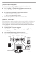
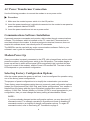
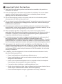
COMSPHERE 3825Plus MODEM QUICK REFERENCE Document No. 3825-A2-GL10-30 Copyright E 2003 Paradyne Corporation. All rights reserved. Printed in U.S.A. Notice This publication is protected by federal copyright law. No part of this publication may be copied or distributed, transmitted, transcribed, stored in a retrieval system, or translated into any human or computer language in any form or by any means, electronic, mechanical, magnetic, manual or otherwise, or disclosed to third parties without the express written permission of Paradyne Corporation, 8545 126th Ave. N., Largo, FL 33773. Paradyne Corporation makes no representation or warranties with respect to the contents hereof and specifically disclaims any implied warranties of merchantability or fitness for a particular purpose. Further, Paradyne Corporation reserves the right to revise this publication and to make changes from time to time in the contents hereof without obligation of Paradyne Corporation to notify any person of such revision or changes. Changes and enhancements to the product and to the information herein will be documented and issued as a new release to this manual. Warranty, Sales, and Service Information Contact your local sales representative, service representative, or distributor directly for any help needed. For additional information concerning warranty, sales, service, repair, installation, documentation, training, distributor locations, or Paradyne worldwide office locations, use one of the following methods: H Via the Internet: Visit the Paradyne World Wide Web site at http://www.paradyne.com H Via Telephone: Call our automated system to receive current information via fax or to speak with a company representative. — Within the U.S.A., call 1-800-870-2221 — Outside the U.S.A., call 1-727-530-2340 Trademarks COMSPHERE is a registered trademark of Paradyne Corporation. All other products and services mentioned herein are the trademarks, service marks, registered trademarks, or registered service marks of their respective owners. Document Feedback We welcome your comments and suggestions about this document. Please mail them to Technical Publications, Paradyne Corporation, 8545 126th Ave. N., Largo, FL 33773, or send e-mail to [email protected]. Include the number and title of this document in your correspondence. Please include your name and phone number if you are willing to provide additional clarification. COMSPHERE 3825Plus Modem Quick Reference Document Number 3825-A2-GL10-30 October 2003 Product Documentation on the World Wide Web Complete documentation for this product is available at www.paradyne.com. Select Support → Technical Manuals → Business Class Analog Modems. Select the following document: 3825-A2-GB30 COMSPHERE 3825Plus Modem User’s Guide To request a paper copy of a Paradyne document, or to speak with a sales representative, please call 1-727-530-2000. Before installing your modem, read the Important Safety Instructions on page 13. 3825Plus Modem Package After opening the modem’s package, check for damage and verify that the following items are present: H 3825Plus modem H Power transformer H One 6-position, 4-wire modular cord (in selected models) If any hardware components are damaged, notify your sales representative. 1 Customer-Supplied Equipment The following customer-supplied equipment is required to complete a data communications system using a 3825Plus modem: H A DTE (a computer or a terminal) with an available RS-232-E serial port. H A shielded RS-232-E cable with a male DB-25 connector at one end to attach to the modem. H One of the following modular dial or leased network interfaces: — RJ11C or RJ14C for dial applications — JM8 for 2-wire leased network interface H For leased-line applications, a JM8 to RJ11 crossover cable. 3825Plus Installation Before installing your standalone modem, make sure your installation site is clean and well-ventilated. Allow space around the modem for installing cables and telephone cords, and make sure the modem is located within reach of an ac power outlet. The rear panel of the 3825Plus modem has the following switches and connectors: H An ON/Off power switch. H A power receptacle for ac power transformer. H A 25-pin DB-25 receptacle for your DTE (computer or terminal). The distance between your modem and DTE should not exceed 50 feet if DTE data rates exceed 19,200 bps. H A 6-pin modular jack for external telephone set use only. H A 6-pin modular jack for dial (PSTN) lines or 2-wire leased lines. On/Off Power Computer Phone Line Dial or Leased-Line Network Interface PC Customer-Supplied Cable Customer-Supplied Cable 495-14695 2 DTE Connection Use the following procedure to connect the RS-232-E cable from the modem to the DTE: " Procedure 1. Make sure the modem’s rear panel power switch is Off. 2. Connect the DB-25-P plug on the cable to the DB-25-S socket labeled COMPUTER on the modem’s rear panel. Use a small screwdriver to fasten the cable to the modem. 3. Connect the other end of the cable to the serial connector on the DTE. Use a small screwdriver to fasten the cable to the DTE. Dial-Line Connection Use the following procedure to connect a 3825Plus to the dial network interface. " Procedure 1. Insert the 6-position, 4-conductor modular plug into the jack labeled LINE. 2. Insert the other end of the modular cord into the dial network interface. 2-Wire Leased-Line Connection Use the following procedure to connect a 3825Plus modem to the 6-pin, center pair, leased-line network interface. A description of the JM8 to RJ11C crossover cable required can be found in the user’s guide. " Procedure 1. Insert the 6-position, 4-conductor modular plug into the jack labeled LINE. 2. Insert the other end of the modular cord into the leased-line network interface. Telephone Connection Use the following procedure to connect the modem to a single-line or two-line telephone: " Procedure 1. Insert the 6-position, 4-conductor modular plug into the jack labeled PHONE. 2. Insert the other end of the modular cord into the telephone. 3 AC Power Transformer Connection Use the following procedure to connect the modem to an ac power outlet: " Procedure 1. Make sure the modem’s power switch is in the Off position. 2. Insert the power transformer’s cylindrical connector into the modem’s rear panel ac power receptacle labeled POWER. 3. Insert the power transformer into an ac power outlet. Communications Software Installation A personal computer commands and controls a dial modem through communications software. This software, which is installed on the PC, uses the AT command set to send instructions to the modem. A dumb asynchronous terminal, however, does not require this software since it can directly send AT commands. The 3825Plus can be used with any major communications software. Refer to your software’s user’s guide for installation procedures. Modem Power-Up Once your modem is properly connected to the DTE, dial or leased lines, and ac outlet, press the modem’s rear panel power switch to the ON position. The modem begins a power-up self-test in which all front panel LEDs momentarily light (note that this also occurs on a reset of the modem), and the Power LED remains ON. The state of other LEDs depends on your modem’s configuration. Selecting Factory Configuration Options After the modem passes the power-up self-test, it can be configured for operation using one of the factory preset configurations. The purpose of preset configurations is to simplify the customization your modem. These factory preset templates contain the most commonly used configuration options (straps) for Asynchronous Dial, UNIX Dial, and Cellular configurations. Your modem is shipped from the factory with the Async Dial default configuration options stored in memory. If UNIX Dial, Cellular (Mobile) or Cellular (PSTN) is more appropriate for your configuration, then you must change the factory setting as described as follows. NOTE: If you have already changed certain configuration options, you may have lost AT command control. For example, operating in Synchronous mode or disabling AT commands results in an inability to change configuration options. To regain AT command control, refer to Recovering AT Commands on page 5. 4 To change a factory template, perform the following steps. " Procedure 1. Use the AT&F&W command to load the appropriate factory configuration to the appropriate storage area. Enter the following: TYPE: AT &Ff &Wn (in all uppercase or all lowercase) Where: f is one of the following Factory configurations: 0 for Async Dial 3 for UNIX Dial 5 for Cellular (Mobile) 6 for Cellular (PSTN) (&F5 and &F6 are available only if ETC is installed.) and Where: n is one of the following storage areas: 0 for Active (Saved) 1 for Customer 1 2 for Customer 2 These three configuration areas are nonvolatile memory locations. Active (Saved) contains the most recently saved changes to any configuration options. In the event of power loss, the modem retrieves these configuration options. Customer 1 and Customer 2 are user-defined configuration storage areas. 2. Press Enter. The selected factory configuration is saved. To establish a connection with a remote modem, use the D (Dial) command. Recovering AT Commands AT commands are issued from asynchronous terminals and personal computers. Certain dialing methods, such as V.25bis and synchronous operation, disable the use of AT commands. The 3825Plus is capable of normal operation, but configuration options cannot be changed unless AT command recovery is performed. The AT Recovery command (AT***) places the modem into a temporary state that restores AT commands. When in this state, the modem’s previous settings are retained except for the following configuration options: H The DTE Dialer Type configuration option (&M and &Q) is set to AT H The Async/Sync Mode configuration option (&M and &Q) is set to Async H The DSR Control configuration option (&S) is set to Forced On H The LSD Control configuration option (&C) is set to Forced On 5 If these settings are not appropriate, then change them to a setting compatible with your current application. The procedures for an AT recovery using an asynchronous terminal or personal computer are listed in the following section. Read through these procedures before performing a recovery: 1. Turn the modem Off and then ON. The modem performs a power-up self-test in which all LEDs light. While this is running, repeatedly press the A key of your DTE’s keyboard (or keep the key depressed if your keyboard automatically repeats characters that way). Keep doing this until As (or as) appear on your DTE screen. (You may use all uppercase or all lowercase characters.) At least three consecutive As must be entered within a 2-second time interval. If these characters are not echoed back to the DTE screen after the power-up self-test is complete, then the modem is still in Dumb mode and maintains its current configuration. Turn the modem Off and then ON again, and repeat Step 1. 2. Once the characters are echoed back to the DTE, TYPE: T*** (The case of this character must be consistent with the case used in Step 1. Mixed case prefixes such as aT or At are not recognized.) This must be entered within 10 seconds after receiving the echoed characters. Press Enter. The screen displays OK. The modem is now in AT Recovery mode, and remains in this state until a Save or power reset occurs. While in this mode, you can use AT commands to make any necessary changes to configuration options. Keep in mind that the &C command is changed to Forced On (&C0), the &M and &Q commands are changed to Async mode with AT commands enabled (&M0 and &Q0), and the &S command is changed to Forced On (&S0). If these settings are not appropriate, then reset them to a desired choice before exiting AT Recovery mode. 3. To save changes, use the &W command: TYPE: AT&Wn Where: n is one of the following storage areas: 0 for Active (Saved) 1 for Customer 1 2 for Customer 2 Press Enter. The modem exits AT Recovery mode and returns to its previous application environment. Only the Active (Saved) area affects modem operation. To move a Customer area to Active (Saved), use the Z command. 6 AT COMMANDS AT COMMANDS (continued) Bold text indicates Async Dial factory defaults. Mn M0 M1 AT A/ Attention Command Prefix/Autobaud Rate. Indicates a command string has started and determines the DTE’s data rate and parity. M2 Repeat Last Command. Reexecutes last command string. (Not preceded with AT or followed by pressing the Return key.) A Answer Mode. Goes off-hook and attempts to establish a connection without waiting for a ring. B0 B1 ITU-T V.21 or V.22 (300 or 1200 bps) Bell 103 or 212A (300 or 1200 bps) Dn Dial. Dials the telephone number n with optional modifiers: T P , W R @ ! ; O Returns modem to Data mode from online Command mode. Qn Q0 Result Codes Enables result codes. Refer to Result Codes section. Disables result codes. Enables originate modem to send result codes to the DTE. Required for most UNIX applications. Q1 Q2 Tone Dial (DTMF) Pulse Dial Pause Wait for Dial Tone Reverse Dial Quiet Answer Hook Flash Return to Command Mode Sn? Displays value of S-Register (where n is the register number). Sn=r Change S-Register. Changes the contents of the S-Register (where n is the register number and r is the assigned value). Vn V0 V1 V2 Result Code Format Displays as digits (Numbers 1). Displays as text. Displays as digits (Numbers 2). Xn Extended Result Codes; Dial Tone Detect; Busy Tone Detect Disables extended result codes 5–16, dial tone detect, and busy tone. Enables extended result codes 5–16, disables dial tone detect and busy tone detect. Enables extended result codes 5–16, dial tone detect, and disables busy tone detect. Enables extended result codes 5–16, disables dial tone detect and enables busy tone detect. Enables extended result codes 5–16, dial tone detect, and busy tone detect. See Result Codes in the user’s guide. Adds EC suffix to extended result codes (20–27) if error control is used, enables dial tone detect and busy tone detect. Adds either V.42 or MNP suffix to extended result codes (20–27) if data compression is used, enables dial tone detect, and busy tone detect. DTE rate appears in CONNECT message instead of line rate, enables dial tone detect and busy tone detect. DS=n Dial Stored Number. Dials the number stored in location n (1–10). En E0 E1 Command Character Echo Disables echo to the DTE. Enables echo to the DTE. H0 H1 Modem goes on-hook. Modem goes off-hook. X2 I0 I1, I9 X3 I11 I19 Displays product code (default 144). Displays 3-digit firmware revision number. Performs an EPROM check. Displays modem’s serial number. Displays modem’s model number. Displays part number of circuit card. Displays firmware release number. Changes value of product code (0=144, 1=240, 2=480, 3=960, 4=120). Firmware checksum. Displays entire firmware revision number. Ln L0,L1 L2 L3 Speaker Volume Selects low volume. Selects medium volume. Selects high volume. X7 I2 I3 I4 I5 I6 I10=n X0 X1 X4 X5 X6 7 Speaker ON/Off Control Speaker always Off. Speaker ON until carrier signal becomes active. Speaker always ON. AT COMMANDS (continued) AT COMMANDS (continued) Yn Y0 Y1 Long Space Disconnect Disable. Enable. &Fn &F0 Zn Z0 Reset and Load Active Loads contents of Active (Saved) into Active (Operating). Loads contents of Customer 1 into Active (Operating). Loads contents of Customer 2 into Active (Operating). Loads contents of Active (Saved) into Active (Operating) and performs a reset. Performs a full modem reset. &F5 &F6 Loads Factory Configuration Loads Async Dial factory configuration options into Active (Operating) configuration area. Cellular (Mobile) (if ETC installed). Cellular (PSTN) (if ETC installed). &Gn &G0 &G1 &G2 V.22bis Guard Tone Disables guard tone. Sets guard tone to 550 Hz. Sets guard tone to 1800 Hz. &In &I10 &I11 • • &I32 &I99 &I100 Dial Transmit Level –10 dBm. –11 dBm. • • –32 dBm. ETC 1.0 (if ETC installed). ETC 1.1 (if ETC installed). &Jn &J0 Dial Transmit Level Type Modem sets dial transmit level to Permissive mode at –9 dBm. &Ln &L0 &L1 &L3 Leased-Line Mode Disables leased-line operation. 2-wire originate leased-line operation. 2-wire answer leased-line operation. Z1 Z2 Z3 Z9 +FCLASS=n +FCLASS=0 +FCLASS=1 +FCLASS=2 Fax class Data Fax Class 1 (EIA 578) Fax Class 2 (EIA/TIA SP-2388) &&P1 &&P1 Clone Remote Copies firmware to the connected modem. &Cn &C0 &C1 LSD Control Forced On. Forces LSD ON at all times. Standard RS232. LSD is ON when the remote modem’s carrier signal is detected. LSD is Off when carrier signal is not detected. Wink When Disc. LSD, normally forced ON, turns Off for approximately 1 to 2 seconds upon disconnect. Follows DTR. State of LSD follows state of DTR. Simulated Control Carrier. State of LSD follows state of remote modem’s RTS. =DTR/DiscOff. State of LSD follows state of DTR except upon a disconnect where DTR remains ON and LSD turns Off. DTR must then toggle Off and ON to turn LSD ON. Required for AT&T DATAKIT dial-out applications. Bridge Retrain. LSD behaves as in Standard RS232, except that it is turned Off when retrain lasts longer than 10 seconds, and ON when no retrain is detected for 10 seconds. &C2 &C3 &C4 &C5 &C6 &Dn &D0 &D1 &D2 &D3 &D4 &Mn,&Qn Async/Sync Mode and DTE Dialer Type &M0,&Q0 Modem operates in Async mode and uses AT command protocol. &M1,&Q1 Modem operates in Sync mode and uses AT command protocol. &M2,&Q2 Modem operates in Sync mode and dials the number stored in directory location 1 when DTR signal turns Off and then ON. &M3,&Q3 Modem operates in Sync mode and uses AT command protocol. &M231, &Q231 Modem operates in Async mode; the DTE Dialer Type is disabled. &M232, &Q232 Modem operates in Async mode; V.25bis Async dialing is enabled. &M233, &Q233 Modem operates in Sync mode; V.25 Bisync dialing is enabled. &M234, &Q234 Modem operates in Sync mode; V.25bis HDLC dialing is enabled. DTR Action Ignore. Modem ignores the DTR (Data Terminal Ready) signal and treats it as always ON. Off=Command Mode. Modem enters online Command mode when DTR is lowered. Standard RS232. DTR signal is controlled by the DTE. Off=Reload Straps. Modem loads Active (Operating) area with Active (Saved) area when DTR is lowered. Controls On-Hook. Modem does not disconnect until DTR lowered by DTE. &Rn &R0 &R1 &R2 8 RTS Action Standard RS232. RTS action is controlled by DTE. Ignores RTS. Modem ignores RTS signal and treats it as always ON. Simulated Control Carrier. State of RTS follows state of LSD. AT COMMANDS (continued) AT COMMANDS (continued) &Sn &S0 &S1 &Zn=x Modem stores telephone number x (and any dial modifiers, up to 40 characters) in directory location n (1–10). For example, the command AT&Z1=555-1234 stores the number 5551234 in directory location 1. To clear a telephone number from a memory location, issue &Zn without entering a telephone number. \An \A0 \A1 \A2 \A3 \A4 \A5 Maximum Frame Size 64 128 192 256 32 16 \Cn \C0 Error Control Negotiate Buffer Data is not buffered during handshaking sequence. Data is buffered up to 4 seconds during handshaking sequence. Data is not buffered during handshaking sequence; however, the modem switches to Buffer mode when it receives an error control fallback character. &S2 &S3 &S4 &S5 &Tn &T0 &T1 &T2 &T3 &T4 &T5 &T6 &T7 &T8 &T9 &Vn &V0 &V1 &V2 &V3 &V4 &V5 DSR Control Forced On. Forces DSR signal ON. Standard RS232. Modem controls DSR signal. Wink When Disc. DSR signal turns Off for approximately 1 to 2 seconds upon disconnecting. Follows DTR. Modem sends DSR to DTE when it receives DTR from DTE. On Early. DSR is Off when modem is in idle state. DSR goes ON when modem enters Data mode. Delay to Data. DSR does not turn ON until the modem enters Data mode. Tests Stops any test in progress. Starts a Local Analog Loopback test). Transmits and receives a 511 BERT pattern. Starts a Local Digital Loopback test. Accepts request from remote modem for a Remote Digital Loopback test. Denies request from remote modem for a Remote Digital Loopback test. Starts a Remote Digital Loopback test. Starts a Remote Digital Loopback test with a Pattern. Starts a Local Analog Loopback test with a Pattern. Starts a self-test. \C1 \C2 \Dn \D0 \D1 \D2 View Configuration Options Displays Active (Operating) configuration options. Displays Active (Saved) configuration options. Displays Customer 1 configuration options. Displays Customer 2 configuration options. Displays telephone numbers stored in directory locations 1–10. Displays the status of VF line characteristics. \D3 \Gn \G0 \G1 \Kn \K0 &Wn &W0 &W1 &W2 Write (Save to Memory) Saves current configuration options in Active (Operating) to Active (Saved). Saves current configuration options in Active (Operating) to Customer 1. Saves current configuration options in Active (Operating) to Customer 2. \K1 \K2 \K3 \K4 &Xn &X0 &X1 &X2 Transmit Clock Source Modem provides internal clock source for synchronous data (Pin 15). Modem uses external source (Pin 24) for clock for synchronous data. Modem uses received signal as clock source for synchronous data. \K5 \K6 9 CTS Control Forced On. CTS is forced ON. Standard RS232 operation. Wink When Disc. CTS turns Off for approximately 1 to 2 seconds upon disconnecting. Follows DTR. The state of CTS follows the state of DTR. Modem-to-Modem Flow Control Disables modem-to-modem flow control. Enables modem-to-modem flow control. Break Buffer Control, Send Break Control, Break Forces Escape Discards data, sends break before data, and enables break forces escape. Discards data, sends break before data, and disables break forces escape. Keeps data, sends break before data, and enables break forces escape. Keeps data, sends break before data, and disables break forces escape. Keeps data, sends data before break, and enables break forces escape. Keeps data, sends data before break, and disables break forces escape. Discards break, disables break forces escape. AT COMMANDS (continued) AT COMMANDS (continued) \Nn \N0 %SAp %SAp Enter Administration Password Permits entry of the Administration Password p (eight digits, 0–9) %SA=p %SA=p Change Administration Password Sets the Administration Password to p (eight digits, 0–9) %SBi=p %SBi=p Set Index for VF Plus DTE Password Changes the VF Plus DTE password in Index i (1–20) to p (eight digits, 0–9) %SDi=p %SDi=p Set Index for DTE Password Changes the DTE password in Index i (1–20) to p (eight digits, 0–9) %SPi %SPi Display Password Displays the password in Index i (1–20). %SPi= %SPi= Delete Password Deletes the password in Index i (1–20). %SR %SR Reset Security Resets the Administration Password to the default value shown above the bar code on the last page of this document, and clears the password table. %SVi=p %SVi=p Set Index for VF Password Changes the VF password in Index i (1–20) to p (eight digits, 0–9) IF IF Clear Error Buffer Clears buffer where information about the last criticial error is stored. IHn IH0 IH1 V.42 bis Data Compression Disables V.42 bis data compression. Enables V.42 bis data compression for transmit only. Enables V.42 bis data compression for receive only. Enables V.42 bis data compression in both the transmit and receive directions. \N1 \N2 \N3 \N4 \N5 \N6 \N7 Error Control Mode Buffer Mode. Modem does not use error control; DTE rate can differ from VF rate. Direct Mode. Modem does not use error control; DTE rate and VF rate must be the same. MNP or Disc. Modem disconnects if it does not connect in MNP mode. MNP or Buffer. Modem connects in Buffer mode if it does not connect in MNP mode. V.42/MNP or Disc. Modem disconnects if it does not connect in V.42 or MNP mode. V.42/MNP or Buffer. Modem connects in Buffer mode if it does not connect in V.42 or MNP mode. LAPM or disconnect. LAPM or buffer. \Qn Flow Control of DTE \Q0, \Q5, \Q6 Disables flow control of DTE. \Q1, \Q4 Enables XON/XOFF flow control. \Q2, \Q3 Modem raises and lowers CTS to start and stop flow control. \Qn Flow Control of Modem \Q0, \Q2, \Q4 Disables flow control of modem. \Q1, \Q5 Enables XON/XOFF flow control. \Q3, \Q6 Modem starts and stops flow control based upon state of DTE’s RTS signal. \Tn \T0 \Tn No Data Disconnect Timer Disables no data disconnect timer. Sets no data disconnect timer to a value n from 1 minute to 255 minutes. %An Sets error control fallback character n to an ASCII value from 0 to 127. %Bn Sets modulation to V.34 and VF rate to n (300, 1200, or 2400 to 33600 in increments of 2400). Default is %B33600. Sets modulation to V.32bis and VF rate to n (2400 to 19200 in increments of 2400) %BLn %Cn %C0 %C1 MNP 5 Data Compression Disables MNP5 data compression. Enables MNP5 data compression. %Rn Sets DTE rate for Asynchronous mode to n (300, 1200, 2400, 4800, 7200, 9600, 12000, 14400, 19200, 28800, 38400, 57600, 76800, or 115200). IH2 IH3 \Xn \X0 \X1 10 XON/XOFF Passthrough Disables transmission of flow control characters to remote modem. Enables transmission of flow control characters to remote modem. S-REGISTERS Register Description Factory Setting 1 Range S0 Auto-Answer Ring Number 0(Disable) or 1–255 rings S2 AT Escape Character 43(+) 0–127 ASCII S3 Carriage Return Character 13 0–127 ASCII S4 Line Feed Character 10 0–127 ASCII S5 Backspace Character 8 0–127 ASCII S6 Blind Dial Pause 2 2–255 seconds S7 No Answer Time-out S8 45 1–255 seconds “,” Pause Time for the Dial Modifier 2 0–255 seconds S10 No Carrier Disconnect 2 0–254 (10ths of a second) or 255(Disable) S12 Escape Sequence Guard Time S14 Asymmetric Rate (Dial) S18 Test Time-out S26 RTS/CTS Delay 0 0–255 seconds S38 DTR Continuous Repeat 0 0(Disable) or 1(Enable) S39 RX Buffer Disconnect Delay 0 0(Disable) or 1–255 seconds S41 Dial Line Rate S43 Train Time S44 Leased-Line Rate S45 Leased TX Level 0 0dBm–15dBm S48 Leased-Line Carrier On Level 0 0=–43dBm; 1=–26dBm S49 Buffer Disconnect Delay S55 Access from Remote 50 0 0(disabled) 27 0 25 10 0 11 0–255 in 20-millisecond increments 0=Enable; 1=Disable 0–255 seconds 1=14400(V.32bis); 2=12000(V.32bis); 3=9600(V.32bis); 4=7200(V.32bis); 5=4800(V.32bis); 6=2400(V.22bis); 7=1200(V.22); 8=1200(212A); 10=0–300(V.21); 11=0–300(103J); 20=19200(V.32terbo); 21=16800(V.32terbo); 27=33600(V.34); 28=31200(V.34); 29=28800(V.34); 30=26400(V.34); 31=24000(V.34); 32=21600(V.34); 33=19200(V.34); 34=16800(V.34); 35=14400(V.34); 36=12000(V.34); 37=9600(V.34); 38=7200(V.34); 39=4800(V.34); 40=2400(V.34) 0=Long; 1=Short 1=14400(V.32bis); 2=12000(V.32bis); 3=9600(V.32bis); 4=7200(V.32bis); 5=4800(V.32bis); 6=2400(V22bis); 18=19200(V.32terbo); 19=16800(V.32terbo); 25=33600(V.34); 26=31200(V.34); 27=28800(V.34); 28=26400(V.34); 29=24000(V.34); 30=21600(V.34); 31=19200(V.34); 32=16800(V.34); 33=14400(V.34); 34=12000(V.34); 35=9600(V.34); 36=7200(V.34); 37=4800(V.34); 38=2400(V.34) 0=Disable or 1–255 in 1-second increments 0=Enable; 1=Disable S-REGISTERS (continued) Register Description Factory Setting Range S56 Remote Access Password 1st and 2nd digits 00 00–99 S57 Remote Access Password 3rd and 4th digits 00 00–99 S58 Remote Access Password 5th and 6th digits 00 00–99 S59 Remote Access Password 7th and 8th digits 00 00–99 S62 V.25bis Coding 0 0=ASCII; 1=EBCDIC S63 V.25bis Idle Character 0 0=Mark; 1=Flag S64 V.25bis New Line Character 0 0=CR+LF; 1=CR; 2=LF S65 Line Current Disconnect 0 0=Enable (8 msec); 1=Enable (90 msec); 2=Disable S66 NMS Call Messages 0 0=Call Connect & Progress; 1=Disable; 2=Call Connect Only; 3=Call Progress Only S67 Directory Location 1 Callback 0 0=Disable; 1=Enable S68 Answer Security 0 0=None; 1=DTE Only; 2=VF and DTE; 3=VF with DTE S69 Make Busy Via DTR 0 0=Disable; 1=Enable S70 Originate Security 0 0=Disable, 1=Enable S74 Network Position S75 Network Management Address S76 Dial Autorate 0 0=Enable; 1=Disable; 2=Start at 4800; 3=Start at 9600 S77 DTR Alarm Reporting 0 0=Disable; 1=Enable S78 Dial Automode 0 0=Enable; 1=Disable; 2=System85 S80 No Data Disc Trigger Signal 3 0=RX or TX; 1=TX; 2=RX; 3=TX and RX S82 Leased Autorate 0 0=Enable; 1=Disable S84 AT Command Mode 0 0=Normal; 1=No Error; 2=No Strap or ERROR S85 Fast Disconnect 0 0=Disable; 1=Enable S88 Straps When Disconnected 0 0=No Change; 1=Reload; 2=Reload, No Change S89 V.42 ARQ Window Size Increase 0 0(6 frames) – 9(15 frames) S90 DTE Rate = VF Rate 0 0=Disable; 1=Enable S91 Cellular Enhancement (if ETC installed) 0 0=Disable; 1=Enable S93 RJ11 Cellular Adapt (if ETC installed) 0 0=Disable; 1=Enable S94 Entry Wait Time 1 0=10 sec; 1=20 sec; 2=40 sec; 3=60 sec S95 VF Prompt Type 0 0=Second Dial Tone; 1=Quiet Answer S96 DTE Password Entry Attempt Limit 0 S97 DTE Password Termination Character 13 1–47, 58–64, 91–96, 123–127 S98 DTE Password Backspace Character 08 1–47, 58–64, 91–96, 123–127 0 255 12 0=Tributary; 1=Control 0–255 (001–256) 0=1 attempt; 1=2; 2=3; 3=4; 4=5 ! Important Safety Instructions 1. Read and follow all warning notices and instructions marked on the product or included in the manual. 2. Slots and openings in the cabinet are provided for ventilation. To ensure reliable operation of the product and to protect it from overheating, these slots and openings must not be blocked or covered. 3. Do not allow anything to rest on the power cord and do not locate the product where persons will walk on the power cord. 4. Do not attempt to service this product yourself, as opening or removing covers may expose you to dangerous high voltage points or other risks. Refer all servicing to qualified service personnel. 5. General purpose cables are used with this product for connection to the network. Special cables, which may be required by the regulatory inspection authority for the installation site, are the responsibility of the customer. 6. When installed in the final configuration, the product must comply with the applicable Safety Standards and regulatory requirements of the country in which it is installed. If necessary, consult with the appropriate regulatory agencies and inspection authorities to ensure compliance. 7. A rare phenomenon can create a voltage potential between the earth grounds of two or more buildings. If products installed in separate buildings are interconnected, the voltage potential may cause a hazardous condition. Consult a qualified electrical consultant to determine whether or not this phenomenon exists and, if necessary, implement corrective action prior to interconnecting the products. 8. Input power to this product must be provided by one of the following: (1) a UL Listed/CSA certified power source with a Class 2 or Limited Power Source (LPS) output for use in North America, or (2) a certified transformer, with a Safety Extra Low Voltage (SELV) output having a maximum of 240 VA available, for use in the country of installation. 9. In addition, since the equipment is to be used with telecommunications circuits, take the following precautions: — Never install telephone wiring during a lightning storm. — Never install telephone jacks in wet locations unless the jack is specifically designed for wet locations. — Never touch uninsulated telephone wires or terminals unless the telephone line has been disconnected at the network interface. — Use caution when installing or modifying telephone lines. — Avoid using a telephone (other than a cordless type) during an electrical storm. There may be a remote risk of electric shock from lightning. — Do not use the telephone to report a gas leak in the vicinity of the leak. 13 Notices ! WARNING: THIS EQUIPMENT HAS BEEN TESTED AND FOUND TO COMPLY WITH THE LIMITS FOR A CLASS B DIGITAL DEVICE, PURSUANT TO PART 15 OF THE FCC RULES. THESE LIMITS ARE DESIGNED TO PROVIDE REASONABLE PROTECTION AGAINST HARMFUL INTERFERENCE IN A RESIDENTIAL INSTALLATION. THIS EQUIPMENT GENERATES, USES, AND CAN RADIATE RADIO FREQUENCY ENERGY AND, IF NOT INSTALLED AND USED IN ACCORDANCE WITH THE INSTRUCTION MANUAL, MAY CAUSE HARMFUL INTERFERENCE TO RADIO OR TELEVISION RECEPTION, WHICH CAN BE DETERMINED BY TURNING THE EQUIPMENT OFF AND ON. THE USER IS ENCOURAGED TO TRY TO CORRECT THE INTERFERENCE BY ONE OR MORE OF THE FOLLOWING MEASURES: Ċ REORIENT OR RELOCATE THE RECEIVING ANTENNA. Ċ INCREASE THE SEPARATION BETWEEN THE EQUIPMENT AND RECEIVER. Ċ CONNECT THE EQUIPMENT INTO AN OUTLET ON A CIRCUIT DIFFERENT FROM THAT TO ĂWHICH THE RECEIVER IS CONNECTED. Ċ CONSULT THE DEALER OR AN EXPERIENCED RADIO/TV TECHNICIAN FOR HELP. THE AUTHORITY TO OPERATE THIS EQUIPMENT IS CONDITIONED BY THE REQUIREMENT THAT NO MODIFICATIONS WILL BE MADE TO THE EQUIPMENT UNLESS THE CHANGES OR MODIFICATIONS ARE EXPRESSLY APPROVED BY PARADYNE CORPORATION. TO COMPLY WITH FCC REQUIREMENTS, A SHIELDED SERIAL DTE CABLE MUST BE USED. ! WARNING: TO USERS OF DIGITAL APPARATUS IN CANADA: THIS CLASS B DIGITAL APPARATUS MEETS ALL REQUIREMENTS OF THE CANADIAN INTERFERENCEĆCAUSING EQUIPMENT REGULATIONS. CET APPAREIL NUMÉRIQUE DE LA CLASSE B RESPECTE TOUTES LES EXIGENCES DU RÈGLEMENT SUR LE MATÉRIEL BROUILLEUR DU CANADA. CE Mark When the product is marked with the CE mark on the equipment label, a supporting Declaration of Conformity can be downloaded from the Paradyne World Wide Web site at www.paradyne.com. Select Support > Technical Manuals > CE Declarations of Conformity. 230 V models now include an autosensing table top power adapter. These models are considered Class A equipment in accordance with CISPR 22 and should not be used in a residential environment. Government Requirements Certain governments require that instructions pertaining to connection to the telephone network be included in the installation and operation manual. Specific instructions are listed in the following sections. 14 United States – Notice to Users of the Telephone Network 1. This equipment complies with Part 68 of the FCC rules. On the equipment is a label that contains, among other information, the FCC registration number and ringer equivalence number (REN) for this equipment. The label is located on the bottom of your modem. 2. The 3825Plus modem connects to the Public Switched Telephone Network (PSTN) using the Universal Service Order Code (USOC) for Permissive mode, RJ11C. An RJ14C jack must be used to connect a two-line telephone to the modem. The Canadian equivalent to RJ11C is CA11A and the Canadian equivalent to RJ14C is CA14A. For connection to an analog private line, an adapter cable should be used to facilitate connection to a JM8 jack. The Canadian equivalent is CA40A. 3. The Ringer Equivalence (REN) is used to determine the quantity of devices which may be connected to the telephone line. Excessive RENs on the telephone line may result in the devices not ringing in response to an incoming call. In most, but not all areas, the sum of the RENs should not exceed five (5.0). To be certain of the number of devices that may be connected to the line, as determined by the total RENs, contact the telephone company to determine the maximum RENs for the calling area. 4. If the modem causes harm to the telephone network, the telephone company will notify you in advance that temporary discontinuance of service may be required. But if advance notice is not practical, the telephone company will notify the customer as soon as possible. Also, you will be advised of your right to file a complaint with the FCC if you believe it is necessary. 5. The telephone company may make changes in its facilities, equipment, operations, or procedures that could affect the operation of the equipment. If this happens, the telephone company will provide advance notice in order for you to make the necessary modifications in order to maintain uninterrupted service. 6. If you experience trouble with this equipment, please contact your sales or service representative (as appropriate) for repair or warranty information. If the product needs to be returned to the company service center for repair, contact them directly for return instructions using one of the following methods: — Via the Internet: Visit the Paradyne World Wide Web site at http://www.paradyne.com — Via Telephone: Call our automated call system to receive current information via fax or to speak with a company representative. — Within the U.S.A., call 1-800-870-2221 — Outside the U.S.A., call 1-727-530-2340 If the trouble is causing harm to the telephone network, the telephone company may request that you remove the equipment from the network until the problem is resolved. 7. The user is not authorized to repair or modify the equipment. 8. This equipment cannot be used on public coin service provided by the telephone company. Connection to Party Line Service is subject to state tariffs. (Contact the state public utility commission, public service commission or corporation commission for information.) 15 9. The Telephone Consumer Protection Act of 1991 makes it unlawful for any person to use a computer or other electronic device to send any message via a telephone fax machine unless such a message clearly contains, in a margin at the top or bottom of each transmitted page, or on the first page of the transmission, the date and time it is sent, and an identification of the business, or other entity, or other individual sending the message, and the telephone number of such business, or other entity, or individual. In order to program this information, follow the steps outlined in the manual supplied with your fax software. 10. An FCC compliant telephone cord with modular plugs may be provided with this equipment. This equipment is designed to be connected to the telephone network or premises wiring using a compatible modular jack which is Part 68 compliant. Canada – Notice to Users of the Telephone Network The Canadian Department of Communications label identifies certified equipment. This certification means that the equipment meets certain telecommunications network protective, operational and safety requirements. The Department does not guarantee the equipment will operate to the user’s satisfaction. Before installing this equipment, users should ensure that it is permissible to be connected to the facilities of the local telecommunications company. The equipment must also be installed using an acceptable method of connection. In some cases, the company’s inside wiring associated with a single line individual service may be extended by means of a certified connector assembly (telephone extension cord). The customer should be aware that compliance with the above conditions may not prevent degradation of service in some situations. Repairs to certified equipment should be made by an authorized Canadian maintenance facility designated by the supplier. Any repairs or alterations made by the user to this equipment, or equipment malfunctions, may give the telecommunications company cause to request the user to disconnect the equipment. Users should ensure for their own protection that the electrical ground connections of the power utility, telephone line and internal metallic water pipe system, if present, are connected together. This precaution may be particularly important in rural areas. CAUTION: Users should not attempt to make such connections themselves, but should contact the appropriate electric inspection authority, or electrician, as appropriate. The Load Number for this equipment is on the label on the modem. The Load Number (LN) assigned to each terminal device denotes the percentage of the total load to be connected to a telephone loop which is used by the device to prevent overloading. The termination on a loop may consist of any combination of devices subject only to the requirement that the total of the Load Numbers of all devices does not exceed 100. If your equipment is in need of repair, refer to the procedure in the United States – Notice to Users of the Telephone Network section. 16 United Kingdom Ringer Equivalence Number The Ringer Equivalence Number (REN) is a customer guide indicating approximately the maximum number of items of apparatus that should be connected simultaneously to the telephone line. The sum of the RENs should not exceed four. This value includes any BT-provided instrument which may be assumed to have a REN of 1 unless marked otherwise. The REN of this modem is 1. Connection to Leased Lines If any other apparatus, including cable or wiring, is connected between the apparatus and the point of connection to any speechband circuit, then all that other apparatus shall comply with the following: 1. The overall transmission characteristics of all that other apparatus shall be such as to introduce no material effect upon the electrical conditions presented to one another by the apparatus and the speechband circuit; and 2. All that other apparatus shall comprise only: (i) apparatus approved for the purpose of connection between the apparatus and a speechband circuit; and (ii) cable or wiring complying with a code of practice for the installation of equipment covered by this part of BS 6328 or such other requirements as may be applicable. This modem is suitable for connection to BT circuits with signalling at a nominal frequency of 2280 Hz and may be connected to multipoint or point to point circuits. The apparatus does not require signalling or otherwise use the frequency range 0 –200 Hz. No dc interaction is intended between the modem and the telephone network. This apparatus may be directly connected to a speechband circuit or connected to a relevant branch system for speechband circuits. Connection to Supply Mains IMPORTANT: The wires in the mains lead supplied with this equipment are coloured in accordance with the following code: Blue — Neutral Brown — Live As the colours of the cores in the mains lead of this equipment may not correspond with the coloured markings identifying the terminals in your plug, proceed as follows: H The core which is coloured blue must be connected to the terminal which is marked with the colour N or coloured black. H The core which is coloured brown must be connected to the terminal which is marked with the letter L or coloured red. 17 All European Countries Safety Notice For pluggable equipment, the mains socket outlet shall be installed near the equipment and be easily accessible. Interconnection circuits between this modem and any other equipment should be such that the equipment continues to comply with the requirements of EN41003 for TNV (Telephone Network Voltage) circuits and EN60950 for SELV (Safety Extra Low Voltage) circuits after making connection between circuits. The power supply must be properly connected and switched on before the modem will work correctly. Japan Notices This is a Class B product based on the standard of the Voluntary Control Council for Interference from Information Technology Equipment (VCCI). If this is used near a radio or television receiver in a domestic environment, it may cause radio interference. Install and use the equipment according to the instruction manual. Restrictions Due to JATE (Japan Approvals Institute for Telecommunications Equipment) regulations, only 3 attempts to dial a number are permitted in a 3-minute period. If a fourth attempt is made to dial the same number, the modem returns the ERROR return code. This restriction applies to the number dialed from the command line or from a directory. An occurrence of the restriction is canceled when a different number is dialed, or when 3 minutes have elapsed. 00282600 *3825-A2-GL10-30* *3825–A2–GL10–30* 18