1
Thank you for purchasing the Minolta QuickScan 35 Plus for Windows. The QuickScan 35 Plus QS-2800
makes it possible for you to scan color and black & white, negative and positive 35mm films using your
personal computer.
The main features of the QuickScan 35 Plus are:
• High-speed scanning with 3-line sensors and a high-brightness fluorescent lamp
• 10 bit A/D converter
• High resolution scans up to 2820 dpi
• Easy to use, versatile software
- TWAIN driver
- QS utility
The Minolta QuickScan 35 Plus is packaged with TWAIN driver software and stand-alone Utility software.
Before using the QuickScan 35 Plus, we recommend you have a working knowledge of the PC and its
operating conventions. Familiarity with the mouse and standard PC menus and commands is necessary
before operating the QuickScan 35 Plus.
Adobe PhotoshopTM is a registered trademark of Adobe Systems Inc.
Microsoft WindowsTM is a registered trademark of Microsoft Inc.
Other corporate names and product names are also registered trademarks.
Changes or modifications not approved by the party responsible for compliance could void the user's
authority to operate the equipment.
This equipment has been tested and found to comply with the limits for a Class B digital device, pursuant to
Part 15 of the FCC rules. These limits are designed to provide reasonable protection against harmful
interference in a residential installation. This equipment generates, uses and can radiate radio frequency
energy and, if not installed and used in accordance with the instruction, may cause harmful interference to
radio communications. However, there is no guarantee that interference will not occur in a particular
installation. If this equipment does cause harmful interference to radio or television reception, which can be
determined by turning the equipment off and on, the user is encouraged to try to correct the interference by
one or more of the following measures:
Reorient or relocate the receiving antenna.
Increase the separation between the equipment and receiver.
Connect the equipment into an outlet on a circuit different from that to which the receiver is connected.
Consult the dealer or an experienced radio/TV technician for help.
This digital apparatus does not exceed the Class B limits for radio noise emissions from digital apparatus as
set out in the Interference-causing equipment standard entitled "Digital Apparatus," ICES-003 of the
Department of Communications.
QuickScan35
3
END-USER LICENSE AGREEMENT
CAREFULLY READ THE LICENSE AGREEMENT BELOW BEFORE OPENING THIS PACKAGED
SOFTWARE. OPENING THIS PACKAGE INDICATES YOUR ACCEPTANCE TO THE TERMS AND
CONDITION BELOW. IF YOU DO NOT AGREE WITH THEM YOU SHOULD PROMPTLY RETURN THE
PACKAGE UNOPENED.
This is a license agreement and not an agreement for sale. Minolta owns, or has been licensed from other
owners, copyrights in the computer programs ("Software"). You obtain no rights to the intellectual property in
the Software other than the license granted to you regarding the Software under this agreement. The title to
the enclosed copy of the copy the Software and any copy made from it is retained by Minolta or such other
owners.
1. LICENSE
You may:
(1) install and use the Software on only one computer at any one time.
(2) make a copy of the Software for backup or installation purposes only in support of the normal and
intended use of the Software.
(3) transfer possession of copies of the Software to another party by transferring a copy of this Agreement
and all other documentation along with at least one complete unaltered copy of the Software, provided that
(i) you must, at the same time, either transfer to such other party or destroy all your other copies of the
Software. (ii) Such transfer of possession terminates you license from Minolta, and (iii) such other party
shall accept and be bound by these license terms by their initial use of the Software.
2. RESTRICTIONS
You shall not without the written consent of Minolta:
(1) use, copy, modify, merge or transfer copies of the Software except as provided herein.
(2) reverse assemble or reverse compile the Software except as permitted by law; or
(3) sublicense, rent, lease or distribute the Software or any copy thereof.
3. LIMITED WARRANTY
Minolta warrants the media on which the Software is recorded to be free from defects in materials and
workmanship under normal use. Warranty details and limitations for the Software are described in the
Statement of Limited Warranty which is supplied with the hardware. With the exception of the foregoing
express warranties applicable to hardware and media only, the Software is not warranted and is provided
"AS IS".
SUCH WARRANTIES ARE IN LIEU OF ALL OTHER WARRANTIES, EXPRESSED OR IMPLIED,
INCLUDING, BUT NOT LIMITED TO, THE IMPLIED WARRANTIES OF MERCHANTABILITY AND
FITNESS FOR A PARTICULAR PURPOSE.
4. LIMITATION OF REMEDIES
In no event will Minolta be liable for any lost profits, lost saving, or any incidental
damages that result from the use or inability to use the Software, even if Minolta or its
Authorized remarketers have been advised of the possibility of such damages or for any claim by you based
on a third party claim.
5. TERMINATION
You may terminate your license at any time by destroying the Software and all your
copies of it or as otherwise described in these terms.
Minolta may terminate your license if you fail to comply with these terms. Upon such
termination, you agree to destroy all your copies of the Software.
6. GOVERNING LAW
This Agreement shall be governed by the laws of the country where the delivery is made to the original
customer.
7. GOVERNMENT END USERS
If you are acquiring the Software on behalf of any unit or agency of the United States Government, the
following provisions apply. The Government agrees: (i) if the Software is supplied to the Department of
Defense (DoD), the Software is classified as "Commercial Computer Software) and the Government is
acquiring only "restricted right" in the Software as that term is defined in Clause 252.227.7013(c)(1) of the
DFARS; and (ii) if the Software is supplied to any unit or agency of the United States Government other than
DoD, the Government's rights in the Software will be as defined in Clause
52.227-19(c)(2) of the FAR or, in the case of NASA, in Clause 18-52.227-86(d) of the
NASA Supplement to FAR
4
QuickScan 35
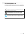
FOR PROPER AND SAFE USE
Various symbols are used throughout this instruction manual and on the product itself for your proper and
safe use of this product, and to prevent personal injury, injury to others, or property damage. An explanation
of the symbols follows. Please read and understand each caution thoroughly before reading this main text of
this instruction manual.
Examples
The outer triangle is for warning, and the symbol inside illustrates what is being warned.
The example at left means beware of electric shock.
The circle with a diagonal slash is for prohibition ("don't do"), and the symbol inside
illustrates what act is prohibited. The example at left means do not disassemble.
The blue circle indicates something you must do, and the symbol inside illustrates how it
should be done. The example at left means you must hold the plug when removing it from
the outlet.
QuickScan35
5
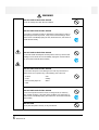
WARNING
RISK OF FIRE OR ELECTRIC SHOCK
Do not use voltage other than what is indicated.
RISK OF FIRE OR ELECTRIC SHOCK
Do not place a container of water or other liquid on the product. If water or
other liquid gets inside the product, it may cause a short resulting in fire or
electric shock. Immediately unplug the unit, discontinue use, and contact a
Minolta Service Facility.
RISK OF FIRE OR ELECTRIC SHOCK
Do not insert small metal objects into the product. This may cause a short
resulting in fire or electric shock. Immediately unplug the unit, discontinue
use, and contact a Minolta Service facility.
RISK OF FIRE OR ELECTRIC SHOCK
Do not misuse the power cord. Damage to the cord may result in fire or
electric shock. Do not perform any of the following acts to the cord:
• Scratch
• Twist
• Place a heavy object on
• Heat
• Pull
• Modify
• Bend
RISK OF FIRE OR ELECTRIC SHOCK
Do not use the product if there is smoke, a strange smell, or under any
other unusual conditions. Use under these conditions may result in fire or
electric shock. Immediately unplug, discontinue use, and contact a Minolta
Service facility.
RISK OF FIRE
Do not place the product in dusty or very humid area.
6
QuickScan 35
WARNING
RISK OF FIRE
This product must have sufficient ventilation while in use. If the ventilation
ducts are blocked, the temperature of the interior may become hot to the
extent that fire will occur. Do not perform the following:
• Place the product on its side or upside down.
• Place the product in a closet, on a shelf, or any area without sufficient
ventilation.
• Place the product on a carpet or mattress.
• Cover the product.
CAUTION
RISK OF FIRE OR ELECTRIC SHOCK
Grasp the plug when removing the power cord from an outlet. Pulling the
cord may damage it resulting in fire or electric shock.
RISK OF FIRE OR ELECTRIC SHOCK
Do not connect the ground to the following:
• Gas pipe
• Telephone ground
• Water pipe
RISK OF ELECTRIC SHOCK
Do not touch the power cord with wet hands.
RISK OF ELECTRIC SHOCK
Do not attempt to disassemble this product. It contains high-voltage
circuits. For repairs, contact a Minolta Service facility.
RISK OF ELECTRIC SHOCK
Connect the ground before use. If the ground is not connected, an
electricity leak may result in electric shock.
RISK OF INJURY
Do not place of the product on an unstable surface.
RISK OF INJURY
Do not sit on, stand on, or push against this product. Also, use caution
when using near children.
QuickScan35
7
TABLE OF CONTENTS
END USER LICENSE AGREEMENT.................................................................4
FOR PROPER AND SAFE USE.........................................................................5
BEFORE YOU BEGIN
Package Contents ...............................................................................................9
System Requirements.........................................................................................9
HARDWARE
Names of Parts .......................................................................................11
Setting the SCSI ID.................................................................................12
Connecting the Scanner .........................................................................13
SOFTWARE
Software for the QuickScan 35 Plus.......................................................19
Installing the Software ............................................................................20
Control Panel and Dialog Boxes ............................................................24
Scan Flow Chart .....................................................................................27
Launching the Software..........................................................................28
Loading the Film .....................................................................................33
Setting the Preferences ..........................................................................37
Specifying the Film Type ........................................................................39
PreScan ..................................................................................................40
Focus and Framing.................................................................................41
Selecting the Scan Mode........................................................................45
Brightness, Contrast, & Color Balance...................................................54
Save and Load........................................................................................60
Scanning & Saving .................................................................................61
TROUBLE SHOOTING.....................................................................................63
USER TECHNICAL SUPPORT........................................................................64
8
QuickScan 35
BEFORE YOU BEGIN
Package Contents
The following contents should be included in this package.
• QuickScan 35 Plus
• SCSI cable SC-6 (High density half 50 pin-full 50 pin)
• Power cord
• 35mm film holder
• SCSI terminator ST-2
• QuickScan 35 Control for Windows
• Instruction Manual
• Warranty card
System Requirements
To use the QuickScan 35 Plus with your PC, you will need the following:
• A PC with a 486 CPU or better.
• Microsoft Windows version 3.1 or newer.
• A minimum of 8 MB of RAM is required.
• A minimum of 60 MB of available hard disk space.
• A SCSI board and ASPI driver for Windows.
- For example, WINASPI.DLL and ASPI driver.
- The following SCSI boards are recommended:
AHA-1522 series
AHA-1542 series
AHA-1520 series
AHA-2940 series
(Windows 95 automatically installs an ASPI driver in PCs with SCSI boards).
• A video board and color monitor capable of displaying a minimum of 256 colors (65,000 is
recommended).
QuickScan35
9
HARDWARE
10
QuickScan 35
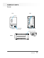
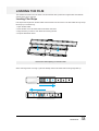
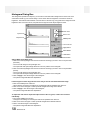
NAMES OF PARTS
Scanner
Front
Back
SCSI port
Film slot
Focus dial
Indicator lamp
Power switch
SCSI ID dial
AC inlet
Terminator power switch
Bottom
QuickScan35
11
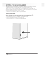
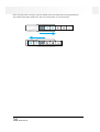
SETTING THE SCSI ID NUMBER
The QuickScan 35 Plus communicates with your PC through a SCSI (pronounced "Scuzzy") connection.
As with all SCSI devices, you will need to set a unique SCSI ID for the QuickScan 35 Plus.
The SCSI ID range of your PC is from 0 to 7. SCSI ID 7 is usually reserved for the SCSI board. The
QuickScan's SCSI ID is set to 5 when the unit is shipped. If no other device connected to your computer is
using this ID, there is no need to change the SCSI ID number.
• If SCSI IDs 8 or 9 are selected, they will be recognized as SCSI ID 6.
Setting the SCSI ID
Before starting, turn the computer and all connected devices OFF.
1. Turn off the PC, the QuickScan 35, and all other connected SCSI devices.
2. Using a small screwdriver, select an unused SCSI ID number.
• Two SCSI devices can not use the same SCSI ID at the same time.
12
QuickScan 35
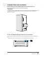
CONNECTING THE SCANNER
Before starting, turn the computer and all connected devices OFF.
If the QuickScan 35 Plus is the only or last item in the SCSI chain
Terminator
If the QuickScan 35 Plus will be the last or only device in your SCSI chain, plug the supplied terminator into
an open SCSI port on the back of the QuickScan 35 Plus. Either SCSI port can be used, there is no
dedicated IN or OUT port.
If Your PC Does Not Supply Power to the Terminator
If your PC does not supply power to the SCSI terminator, set the QuickScan's terminator power switch to
ON.
• Refer to your computer manual to determine if your PC supplies power to the terminator.
QuickScan35
13
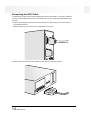
Connecting the SCSI Cable
Your QuickScan 35 Plus scanner comes equipped with the SC-6 SCSI cable. If you require a different
connector to link the QuickScan 35 Plus to your SCSI chain, see your dealer for the appropriate SCSI
connector.
1. Plug the 50 pin half pitch end of the SC-6 SCSI cable into the open SCSI port on the rear panel of
your QuickScan 35 Plus.
• Either SCSI port can be used, there is no dedicated IN or OUT port.
2. Plug the other end of the SC-6 SCSI cable into the SCSI port on the rear of the PC.
14
QuickScan 35
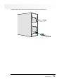
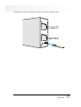
3. Plug the power cord into the scanner's AC socket, then plug it into a grounded outlet.
QuickScan35
15
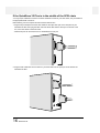
If the QuickScan 35 Plus is in the middle of the SCSI chain
You may require a different connector to link the QuickScan 35 Plus to your SCSI chain, see your dealer for
the appropriate SCSI connectors.
Before starting, turn the computer and all connected devices OFF.
1. Plug the 50 pin half pitch end of the SCSI cable into the open SCSI port on the rear panel of your
QuickScan 35 Plus, then plug the other end of the SCSI cable into the SCSI port on the rear of the
PC, or the next device in the SCSI chain.
• Either SCSI port can be used, there is no dedicated IN or OUT port.
2. Plug the SCSI cable from the next device in your SCSI chain into the open port on the back of the
QuickScan 35 Plus.
16
QuickScan 35
3. Plug the power cord into the scanner's AC socket, then plug it into a grounded outlet.
QuickScan35
17
SOFTWARE
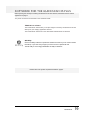
SOFTWARE FOR THE QUICKSCAN 35 PLUS
Before opening the envelope containing the QuickScan 35 Plus software, read the End User License
Agreement on page 4.
Two pieces of software are included on the QuickScan disks:
TWAIN driver software
The TWAIN driver software lets you acquire images scanned by the QuickScan 35 Plus
directly into your imaging application software.
The TWAIN driver software is on the disk marked TWAIN Driver for Windows.
QS Utility
Use the QS Utility software to operate the QuickScan 35 Plus if you do not have Adobe
Photoshop or you have many images you want to scan at a specific file size.
The QS Utility is on the floppy labeled QS 35 Utility for Windows.
Please refer to the system requirements listed on page 9.
QuickScan35
19
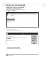
INSTALLING THE SOFTWARE
Installing the Software with Windows 3.1
1. Startup the PC and open the Program manager.
2. Insert the floppy marked QS35 Control for Windows into the PC.
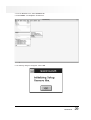
3. Select Run... from the File menu.
4. Type A:\SETUP and click on OK.
• If your 3.5" disk drive is drive B, type B:\SETUP.
• The dialog box "Setup Initializing" will appear.
• The Install Directory dialog box will appear next.
20
QuickScan 35
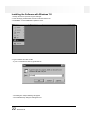
5. Enter the install directory and click on OK.
• The default install directory is C:\QS35. If you want to change the directory, click on Browse....
6. When the install is complete, the "Install Successful" dialog box will appear. Click on OK.
QuickScan35
21
Installing the Software with Windows '95
1. Startup the PC and open the Program manager.
2. Insert the floppy marked QS35 Control for Windows into the PC.
3. Select Run... from the Start button pulldown menu.
4. Type A:\SETUP and click on OK.
• If your 3.5" disk drive is drive B, type B:\SETUP
• The dialog box "Setup Initializing" will appear.
• The Install Directory dialog box will appear next.
22
QuickScan 35
5. Enter the install directory and click on OK.
• The default install directory is C:\QS35. If you want to change the directory, click on Browse....
6. When the install is complete, the "Install Successful" dialog box will appear. Click on OK.
QuickScan35
23
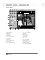
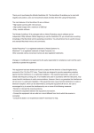
CONTROL PANEL & DIALOG BOXES
Control Panel
1
2
3
4
20
21
Cropping Frame
5
6
7
9
8
10
11
12
13
18
14
15
16
1. Preference button
2. Eject button
3. Save button
4. Load button
5. Film Type pop-up menu
6. Rotate button
7. Flip button
8. Color correction button
9. Focus button
10. Scan mode pop-up menu
24
QuickScan 35
17
19
11. Scan pitch pop-up menu
12. Pixel box
13. Reset button
14. PreScan button
15. Cancel button
16. Scan button
17. Disc space indicator
18. File size indicator
19. Zoom preview button
20. Image size indicator
21. Color information indicator
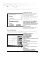
Preference Dialog Box
Click on the preference button to display the preference dialog box. Here, you can select the desired color
correction mode and turn the Auto Brightness and Auto Eject functions on and off.
1. Standard Mode check box
In standard mode, the color balance, black level,
and brightness are adjusted with slider bars.
2. Professional Mode check box
In professional mode, the curves dialogue box and
histogram dialogue box give you precise image
correction capability.
3. Auto Brightness check box
Auto Brightness automatically compensates for the
density range of positive film. When scanning
underexposed color slides, select Auto Brightness
to obtain image data with suitable brightness
values. Auto Brightness is only effective when Color
Pos. has been selected in the Film Type pop-up
window.
4. Auto Eject check box
When selected, the film is automatically ejected
after the scanning operation is finished.
1
2
3
4
Curves Dialog Box
With the curves dialog box, you can control the brightness and color of the scanned image. Changes to all
curves are automatically applied to the image in the scanning window.
1
2
3
4
5
6
7
9
8
1. Master Tone Curve check box
2. R Tone Curve check box
3. G Tone Curve check box
4. B Tone Curve check box
5. Input level display
Displays the input level for the selected point on the
tone curve.
6. Output level display
Displays the output level for the selected point on
the tone curve.
7. Reset button
Click on the reset button to return to the curves to
their original settings.
8. Load button
Click on the load button to load previously saved
settings.
9. Save button
Click on the save button to save the settings
currently displayed in the curves dialog box.
QuickScan35
25
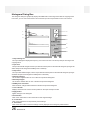
Histogram Dialog Box
The histogram dialog box graphically displays the RGB levels of the image area inside the cropping frame.
From here, you can control the minimum and maximum input and output levels for each color channel.
1
4
2
5
3
6
7
8
9
11
10
1. Output Histogram
The output histograms display the frequency of occurrence of each color level (0-255) for the image in the
cropping frame.
2. Input level
The input level slider triangles set the input white and black points for the selected histogram (changes will
affect all input level histograms if RGBSynchro is selected).
3. Output level
The output level slider triangles, set the output white and black points for the selected histogram (changes
will affect all input level histograms if RGBSynchro is selected).
4. White Eyedropper
Use to set the brightest value for one or all three output level histograms.
5. Black Eyedropper
Use to set the darkest value for one or all three output level histograms.
6. RGBSynchro check box
When checked, changes will be reflected in all three output level histograms.
7. Level indicator
Displays the level for the cursers current position on the input and output scales.
8. Apply button
Applies changes to the histogram.
9. Reset button
Click on the reset button to return the levels to their original settings.
10. Load button
Click on the load button to load previously saved settings.
11. Save button
Click on the save button to save the settings currently displayed in the histogram palette window.
26
QuickScan 35
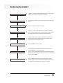
SCAN FLOW CHART
Insert Film
1
Place film in the film holder emulsion side down. Insert the film
holder to the scanner as indicated on the holder.
Specify Film Type
2
Select the type of film you are scanning in the Film Type pop-up
menu.
Preview
3
Click on PreScan to preview your image.
4
Focus, flip, crop, or rotate the image if necessary. Frame the
area you want to scan using the cropping frame. Click and hold
the Zoom Preview button to view the scanning area only.
Color Correct
5
Correct the color of your image if necessary using the slider
bars (Standard Color Correction Mode) or the RGB curves
(Professional Color Correction Mode).
Scan
6
Click on SCAN to scan the image.
7
If you are using the TWAIN Driver software save the file by
selecting Save As... from the File menu.
If you are using the QS Utility software, the Save dialog box will
appear. Enter a file name and select the location to save the file
to, then click on SAVE.
8
Click on EJECT to eject the film manually after you have
scanned the film. If you selected the Auto Eject check box, the
film will eject automatically after scanning is complete.
Focus and Framing
Save the File
Film Eject
QuickScan35
27
LAUNCHING THE SOFTWARE
TWAIN Driver
• This manual has been written using Adobe Photoshop 3.0 as the example imaging application. However,
any imaging application capable of using TWAIN sources can be used with the QuickScan 35.
1. Turn on the QuickScan 35 Plus, then turn on your PC.
2. Launch the photo application software.
3. Choose Acquire from the File menu and choose Select TWAIN Source....
28
QuickScan 35
4. From the Sources menu, select QuickScan 35.
5. Select TWAIN... from Acquire in the File menu.
6. The following dialog box will appear. Click on OK.
QuickScan35
29
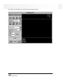
The QuickScan 35 Plus dialog box and preview window appear after setup.
30
QuickScan 35
QS Utility
1. Turn on the QuickScan 35 Plus, then turn on your PC.
2. Double-click on the QS Utility icon.
3. The software will launch automatically.
QuickScan35
31
Interface can not be Confirmed
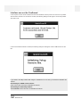
If the computer cannot confirm interface because the QuickScan 35 Plus power is off or there is a problem
with the SCSI connection or the SCSI ID number, the following dialog box will appear. Correct the problem
and click on OK.
If the scanner detects that film is loaded, the following dialog box will appear. Click on OK and remove the
film.
If you switch to the utility software after using the TWAIN driver or vice versa, you will have to reinitialize the
scanner.
Reinitializing the TWAIN Control Software
Press control, shift, and I keys to reinitialize the scanner.
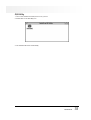
Reinitializing the QS35 Utility Software
Select Initialize from the File menu to reinitialize the scanner.
32
QuickScan 35
LOADING THE FILM
The QuickScan 35 Plus can scan 35mm color and black & white, positive and negative film. Mounted film
and film strips can be scanned.
Loading Film Strips
Film strips must be placed in the film holder before insertion into the scanner. The film holder will only accept
film strips up to 6 frames long.
1. Open the film holder.
2. Place the film on the film holder with the emulsion side down.
3. Align the frame you want to scan within the scanning window.
4. Snap the film holder closed.
Clean the film before placing it in the film holder.
When scanning frames 1 through 3, place the filmstrip into the film holder with the image right side up.
QuickScan35
33
When scanning frames 4 through 6, place the filmstrip into the film holder with the image upside down.
The preview image will be upside down; click on the Rotate button to correct the image.
34
QuickScan 35
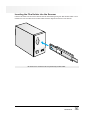
Inserting the Film Holder into the Scanner
Insert the film holder into the scanner film slot with the white lettering facing left. Slide the film holder in until
resistance is met. The white line on the film holder should be aligned with the front of the film slot.
Be careful not to scratch the film not protected by the film holder.
QuickScan35
35
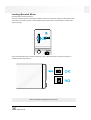
Loading Mounted Slides
Mounted slides can be inserted as is.
The front and back surfaces of the slide are different. The front, or base, has a glossy surface and the back,
or emulsion, has a matte surface. Load the slide into the scanner narrow end first with the emulsion side
facing to the right.
Insert vertical images into the scanner horizontally. Click on the Rotate button to return the image to a
vertical orientation after prescan.
Clean the slide before loading it into the scanner.
36
QuickScan 35
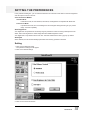
SETTING THE PREFERENCES
In the preference dialog box, you can select the desired color correction mode and turn the auto brightness
and auto eject functions on and off.
Color Correction Modes
Standard Mode
In standard mode, the color balance, black level, and brightness are adjusted with slider bars.
Professional Mode
In professional mode, the curves dialogue box and histogram dialogue boxes give you precise
image correction capability.
Auto Brightness
Auto brightness compensates for the density range of positive film. When scanning underexposed color
slides, select auto brightness to obtain image data with suitable brightness values.
Auto brightness is only effective when Color Pos. has been selected in the Film Type pop-up window.
Auto Eject
When selected, the film is automatically ejected after the scanning operation is finished.
Setting
1. Click on the Preference button.
• The preference dialog box will appear.
2. Click on the desired settings.
2. Click on OK to close the window.
QuickScan35
37
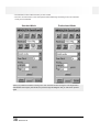
• The selected functions will be set after you click on OK.
• The color correction button in the control panel window will change according to the color correction
mode you have selected.
Standard Mode
Professional Mode
Select your preferences before scanning. If the color correction mode is changed or auto brightness is
selected after the image is prescanned, the preview image will disappear and you will need to prescan
again.
38
QuickScan 35
SPECIFYING THE FILM TYPE
Specifying the type of film you are scanning is necessary to accurately reproduce the image. There are four
types of film to choose from:
• Color Negative
• Color Positive
• Black & white negative • Black & white positive
Select the type of film you are scanning in the Film Type pop-up menu.
QuickScan35
39
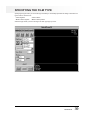
PRESCAN
Click on PreScan to preview the image. The preview image will appear in the preview window.
• Grab the title bar to move the QuickScan 35 Plus dialog box to any convenient location on the screen.
Do not insert another mount or anything metallic into the film slot while scanning or preview
scanning film in slide mounts. A scanning error or breakdown may occur.
40
QuickScan 35
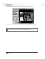
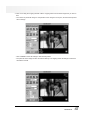
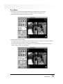
FOCUS AND FRAMING
Manual Focus
Focusing is not normally necessary with the QuickScan 35 Plus, however it is recommended when your final
image will be large, the film strip is curled, or a paper slide mount is warped.
1. Click on the focus button. The curser will change to the focus icon.
2. Position the focus icon over the area you want to focus and click the mouse button.
• The focus indicator window will appear.
3. Turn the focus dial on the front of the QuickScan 35 Plus until the black box and the red bar are their
longest.
4. Click on OK when you have finished focusing.
SHORT CUT
Press option and click on the area you want to focus on. The focus dialog box will appear.
QuickScan35
41
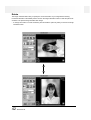
Rotate
The image orientation button lets you specify the correct orientation of your image before scanning.
Horizontal orientation is the default position. Click on the image orientation button to rotate the picture 90°
clockwise. The preview image will reflect this change.
• To change the rotation to counter-clockwise, press and hold the option key while you click on the image
orientation button.
42
QuickScan 35
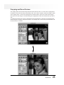
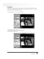
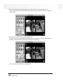
Cropping and Zoom Preview
The cropping frame surrounds the image area that will be scanned. Click on a corner of the cropping frame
to enlarge or reduce the size frame proportionally. Click on the sides to expand or reduce the height or width
of the cropping frame. To move the cropping frame to another position, click on the inside of the cropping
frame (the cursor will change to a hand) and drag the cropping frame until it surrounds the area you want to
scan.
To preview the scanning area, click on and hold the Zoom Preview button. The area in the cropping frame
will be enlarged to the limits of the preview window. The enlarged view of the scanning area will remain until
the mouse button is released.
QuickScan35
43
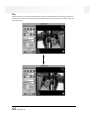
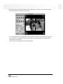
Flip
The flip button lets you reverse the image before scanning. The default position is the image viewed from
the film base side. Click on the flip button to flip the image left-to-right horizontally. The preview image will
reflect this change.
44
QuickScan 35
SELECTING THE SCAN MODE
The QuickScan 35 Plus lets you select from three convenient scan modes:
Quick Mode
Quick mode is the fast and easy way to make a scan. You select the scan pitch to determine output size
(see Scan Pitch and Resolution on page 48).
Pixel Mode
In this mode you select the number pixels in the image and the scanning area. Pixel mode is convenient
when your final output device will be a monitor.
Print Mode
Print mode lets you lock the image size and resolution to control the final image size and resolution to match
that of your printer.
The scan speed will change according to the PC you are using and the amount of RAM installed. Generally,
scanning will be slower in the Pixel and Print modes than in the Quick mode.
QuickScan35
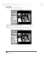
45
Quick Mode
1. Select Quick Mode from the Scan Mode pop-up window.
2. Select a scan pitch from the Scan Pitch pop-up menu.
• The lower the scan pitch number the greater the resolution. See "Scan Pitch And Resolution" on
page 48.
• The number of pixels (W x H) will change to compensate for the changes in scan pitch.
46
QuickScan 35
3. Click on and drag the cropping handles until the cropping frame surrounds the image area you want to
scan.
• The number of pixels will change to compensate for the changes in scan pitch, but the final output size
will not change.
• Click on Reset to return all settings to their default position.
• The pixel size of the image can also be entered directly. The cropping frame will change to reflect the
dimensions entered.
QuickScan35
47
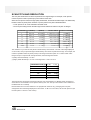
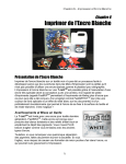
SCAN PITCH AND RESOLUTION
The scan pitch determines how data is acquired from the original image. For example, a scan pitch of 1
means one piece of data is 'picked up' by each element of the CCD.
When the scan pitch is small, the image quality will be better, but the file size will be larger. The relationship
between number of pixels (at the maximum crop size) and the scan pitch is illustrated below.
• A scan pitch of 24 can not be selected in the Quick mode.
• The scan pitch setting used for the last image scanned will remain until the scan pitch is changed.
SCAN PITCH
X (PIXELS)
Y (PIXELS)
1
4032
2688
10838016
32MB
2
2016
1344
2709504
7.9MB
3
1344
896
1204224
3.5MB
4
1008
672
677376
2.0MB
6
672
448
301056
882KB
12
336
224
75264
220KB
24*
168
112
18816
55KB
TOTAL # PIXELS
APPROX. FILE SIZE
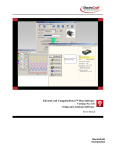
The resolution of your monitor and printer is determined by the hardware. The size of the image displayed
on the screen, and your printed image is determined by the number of pixels in the image. For example, the
maximum possible number of pixels (or dots) in an image scanned at a pitch of 1 is 4032 x 2688. If this
image is output on a printer with 400 dpi resolution, the final image size will be:
x (width): 4032 dots/400 dpi = 10.08 in.
y (height): 2688 dots/400 dpi = 6.72 in. Final Image Size = 10.08 x 67.72 in.
X (in.)
Y (in.)
2820
1.43
0.95
1200
3.36
5.44
600
6.72
4.48
400
10.08
6.72
300
13.44
8.96
150
26.88
17.92
PRINTER RESOLUTION (dpi)
The final print size for images scanned at maximum crop and resolution, for different printer resolutions is
shown above. The resolution of most printers will vary from 140~ 360 dpi. The maximum scan resolution of
the QuickScan 35 is 1200 dpi.
Most monitors have a screen resolution of 72 dpi (Flexscan monitors vary). Changing the scan pitch
changes the size of the image displayed on the monitor. To fill a 13 inch monitor, set the scan pitch to 6 (set
the scan pitch to 4 to fill a 17 inch screen).
48
QuickScan 35
Pixel Mode
Pixel Mode lets you specify the final size of the image you are scanning. This is helpful when you want to
make sure the image fills the display it will be viewed on. For example, to fill the screen on a VGA monitor,
the image size would need to be 640 by 480 pixels.
1. Select Pixel Mode from the scan mode pop-up window.
2. Enter the width and height in the size box.
• You will notice a change in the size of the cropping frame.
3. Click on Lock to lock the file size.
QuickScan35
49
4. Click on the inside of the cropping frame (the cursor will change to a hand) and drag it until the cropping
frame surrounds the image area you want to scan.
• If you change the size of the cropping frame, the scan pitch will change to compensate for the changes in
the scanning area. If the file size is not locked, the number of pixels will change to compensate for the
changes in the scanning area.
• Click on Reset to return all settings to their default position.
50
QuickScan 35
Print Mode
In Print Mode, you can specify the output dimensions and resolution of your final image.
• The output resolution set in Print Mode is also valid for Standard and Pixel modes.
1. Select Print Mode from the scan mode pop-up menu.
2. Enter the desired output resolution.
• The QuickScan 35 Plus is capable of scanning resolutions from 36 - 1200 dpi. If a resolution outside of
this range is entered, a resolution of either 36 or 1200 will be set.
• The scan pitch selected in Quick mode will affect your resolution options. For maximum resolution
options, select scan pitch 1 in Quick mode.
QuickScan35
51
3. Enter the final image size (Width and Height) in the Image Size Box or use the cropping frame.
• Use the Units pop-up menu to change the units of measure. Size can be entered in inches, centimeters,
points, or picas.
4. Click on the Lock check box to lock your final image size.
• Changing the scan pitch will not affect the standard mode settings unless the scanners limits have been
breached. If breached, the image dimensions will change to compensate.
• Click on Reset to return all settings to default position.
52
QuickScan 35
RESOLUTION, RESIZING, AND RESAMPLING
Image resolution is the number of pixels per inch (ppi or dpi) that represent your scanned image. Image size
(width x height) and image resolution determine your file size. The greater the dpi, the larger your file size
will be. Larger files sizes do take longer to print and scan than smaller file sizes. The general rule for image
resolution when scanning for quality is "bigger is better". We recommend you scan your image using the
highest resolution your output device is capable of handling. For example, if your printer's resolution limit for
a 6 x 4 inch image is 600 dpi, scan using those settings.
As all the image adjustments are made before scanning, there is no need for QuickScan 35 Plus users to
worry about pixel resampling or interpolation (two computer functions that can result in loss of image
quality). Users of image editing software (such as Adobe Photoshop) however, can adjust image size and
resolution in the application after scanning. If done incorrectly, resizing can result in interpolation. Please
refer to your software user's guide for additional information regarding resolution, file size, resizing,
as well as scanning.
QuickScan35
53
BRIGHTNESS, CONTRAST, & COLOR BALANCE
The Minolta QuickScan 35 Plus gives you both Standard and Professional options to adjust your image
before scanning. The Standard mode is intuitive and ideal for hobbyists. The Professional mode gives you
all the image information and tools necessary to control the output quality of your scan.
STANDARD CORRECTION MODE
1. Before scanning, click on the Standard check box in the preference dialog box.
2. Click on the Color Correction button in the control panel.
• The control panel changes to the color correction control panel
HINT: Correcting the brightness and contrast first may eliminate the need for color corrections.
3. Move the appropriate slider bars to correct imbalances.
• Click and drag the slider bars to make large corrections. Click on the arrows to make smaller
adjustments.
• The values next to the controls show for the amount of change. The correction values range from -20 to
+20.
• The preview image will reflect the adjustments.
R
G
B
Black Level
Brightness
Reset
Black Level
Black Level lets you control the brightness of the image shadow area. Moving the slider bar to the right
makes the shadow areas darker. Moving it to the left makes the shadow areas lighter.
Brightness
Moving the slider bar to the right increases overall brightness. Moving it to the left decreases overall
brightness.
RGB Color Correction Controls
The RGB color correction controls let you correct unwanted color casts.
R: Move to the right to make the image more red. Move to the left to make the image less red.
G: Move to the right to make the image more green. Move to the left to make the image less green.
B: Move to the right to make the image more blue. Move to the left to make the image less blue.
• Click on Reset to return all settings to their default position.
54
QuickScan 35
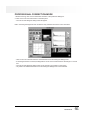
PROFESSIONAL CORRECTION MODE
1. Before scanning, click on the Professional check box in the preference dialog box.
2. Click on the Color Correction button in the data panel.
• The Curves and Histogram dialog boxes will appear.
HINT: Correcting the brightness and contrast first may eliminate the need for color corrections.
• Click on the color correction button to close both the Curves and Histogram dialog boxes.
• If the image has been corrected, the diagonal line on the color correction button will change to a curved
line.
• The Curves and Histogram dialog boxes can be moved to any position on the screen.
• Any button not hidden behind the Curves and Histogram dialog boxes can be selected.
QuickScan35
55
Curves Dialog Box
Using the curves dialog box, any point along the tone curve can be adjusted for all color tones (Master) or
for the individual RGB channels. Changing the shape of the tone curve, changes the output level for each
corresponding input level.
Pulling up on the tone curve increases the output level, making the image lighter and the color more red,
green, or blue. Pulling down on the curves decreases the output level, making the image darker and the
color less red, green, or blue.
1. Click on the check box of the curve you want to adjust.
• The Master curve controls the output brightness of the scanned image.
• The R, G, and B curves control the output color levels of the scanned image.
2. Click on and drag the portion of the curve you want to change. The change will be reflected in the preview
image.
• Pull the curve up to increase the output level.
• Pull the curve down to decrease the output level.
3. Click on the Reset button to return the selected curve to its default setting.
56
QuickScan 35
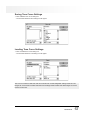
Saving Tone Curve Settings
1. Click on Save in the curves dialog box.
• The standard Windows Save dialog box will appear.
Loading Tone Curve Settings
1. Click on Load in the curves dialog box.
• The standard Windows Load dialog box will appear.
The Tone Curve files for black and white and color film are not interchangeable. Settings saved for color
images can not be used for a black and white scan. Settings saved for black and white images can not be
used for a color scan.
QuickScan35
57
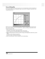
Histogram Dialog Box
The histograms represent the frequency of occurrence of the 256 levels of brightness for each of the color
channels that make up your scanned image. Level 0 is the minimum brightness. Level 255 is maximum
brightness. The midtones fall in between. If the bar above a level is long, many pixels in the image have that
brightness value. If the bar is short, few pixels in the image have that output brightness value.
White Point
Input Level
Black Point
Output Level
RGBSynchro
Level Indicator
Apply Button
Reset Button
Load Button
Save Button
Setting White Point /Black Point:
1. Click on the white eyedropper then click on the area of the image you want to scan in as pure white
(level 255).
• The cursor will change to the eyedropper icon.
• The input level white point triangle will move to its new position on the histogram.
2. Click on the black eyedropper then click on the area of the image you want to scan in as pure black
(level 0).
• The cursor will change to the eyedropper icon.
• The input level black point triangle will move to its new position on the histogram.
3. Click on Apply to view the changes to the histogram.
• The preview image will reflect the adjustments.
If the histogram contains large flat-line areas and you are still not satisfied with the image:
1. Click on the RGBSynchro check box.
• When selected, changes in the settings of one histogram will be repeated in the other two.
2. Click on and move the upper or lower input limit triangles to the edge of the flat line.
3. Click on Apply to view the changes to the histogram.
• The preview image will reflect the adjustments.
To adjust the max and min input and output values of the red, green, or blue color channels
individually:
1. Turn off the RGBSynchro function.
• Changes in the settings of one histogram will not be repeated in the other two.
2. Click on and move the upper or lower input limit triangles to the desired locations.
3. Click to view the changes to the histogram.
• The preview image will reflect the adjustments.
58
QuickScan 35
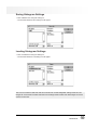
Saving Histogram Settings
1. Click on Save in the Histogram dialog box.
• The standard Windows Save dialog box will appear.
Loading Histogram Settings
1. Click on Load in the Histogram dialog box.
• The standard Windows Load dialog box will appear.
The Tone Curve files for black and white and color film are not interchangeable. Settings saved for color
images can not be used for a black and white scan. Settings saved for black and white images can not be
used for a color scan.
QuickScan35
59
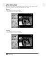
SAVE AND LOAD
The Save and Load buttons let you save and load the current scanner settings. Saved settings are useful
when scanning a series of images taken under similar photographic conditions.
Saving
1. Click on Save in the QuickScan's control panel.
• The standard Windows Save dialog box will appear.
Loading
1. Click on Load in the QuickScan's control panel.
• The standard Windows Load dialog box will appear.
60
QuickScan 35
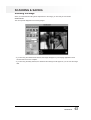
SCANNING & SAVING
Scanning the Image
When you have finished making all the adjustments to the image, you are ready to scan the film.
Click on Scan.
The control panel disappears and scanning begins.
• If you are using the TWAIN driver software, the image will appear in your imaging application's main
window when the scan is complete.
• If you are using the Utility software, the Windows Save dialog box will appear so you can save the image
data.
QuickScan35
61
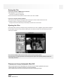
Saving the File
If you are using the TWAIN driver software:
Select Save As... from the File menu.
• The Save As dialog box will appear.
Enter the file name and the location to save the file to, then click on Save.
If you are using the Utility software:
The Windows Save dialog box will appear after the image is scanned. Enter the file name and
choose the location to save the file, then click on Save.
• Images scanned and saved using the QS Utility are saved in a PICT2 format.
Ejecting the Film
Eject the film after scanning and before turning the Quickscan off. Click on Eject to eject the film manually. If
the Auto Eject check box in the preference dialog box was selected, the film will automatically eject when
scanning is complete.
Do not remove the film holder from the scanner until it has been properly ejected.
Removing the film, changing the frame, and inserting the film again without ejecting the film properly will
cause image distortions.
Fluorescent Lamp Automatic Shut Off
The fluorescent light source automatically turns off if the PC has not been operated for two hours.
The lamp will come on again the next time you use the QuickScan.
Set-up will take about 30 to 60 seconds before the fluorescent lamp glows again.
62
QuickScan 35
TROUBLE SHOOTING
Q After connecting the QuickScan 35, Windows does not operate correctly.
A Turn the power switch OFF, check the SCSI ID and connections.
A Disconnect only the QuickScan 35. Check the other SCSI devices with the Windows ASPI check
command.
Q During Preview Scan or Scan, the QuickScan stops.
A Check the System Requirements on page 9.
A Turn the power switch OFF, check the SCSI ID and connections.
A Disconnect only the QuickScan 35. Check the other SCSI devices with the Windows ASPI check
command.
Q Operation stops during plug-in setup, preview, or scan.
A Check System Requirements on page 9.
A Turn power off, then check SCSI cable, SCSI connection, and SCSI ID number.
Q Insufficient Memory message appears.
A Close other Windows applications.
A Change Windows control panel setting to the 386 enhanced mode and increase the size of the swap file.
A Repeat the scan. If the operation stops again, the photo application software's buffer is full. Restart the
photo application software.
Q Grain is visible when scanning high-speed film.
A Slightly defocus the image using manual focus.
Q Color is unusual when scanning color negative film, especially images taken under fluorescent lighting.
A Scan again or correct the color using the color adjustment function.
Q "Change the fluorescent lamp" message appears.
A The fluorescent lamp needs to be changed. Contact a Minolta Service facility.
Q Film is not inserted, but "Film loaded or Scanner Error detected..." message appears.
A The fluorescent lamp needs to be changed. Contact a Minolta Service facility.
QuickScan35
63
USER TECHNICAL SUPPORT
For questions regarding installation, SCSI interface recommendations, and application compatibility, please
contact your dealer or contact us toll free.
Technical Support
1-800-808-4888
Monday-Friday 8:30-5:00 (EST)
Minolta Corporation
101 Williams Dr.
Ramsey, NJ 07446
(201) 825-4000
IMPORTANT
When calling Minolta Technical Support, please have the following information ready.
1. Computer information
• The make and model of your computer
• The available application RAM
• System software version number
• Information on any other connected SCSI devices
2. The version number of your QuickScan 35 driver software
3. The symptoms of the problem you are having.
• The messages that appear on the screen when the problem occurs.
• The frequency of occurrence of the problem.
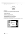
To Determine the Version Number of Your Driver Software
Click on the Minolta logo in the upper left hand corner of the control panel. The QuickScan 35 information
window will appear.
64
QuickScan 35