1
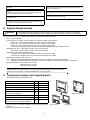
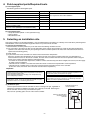
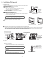
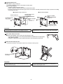
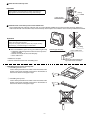
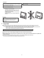
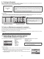
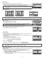
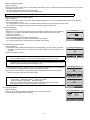
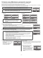
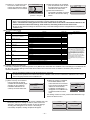
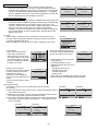
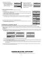
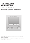
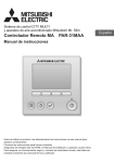
GB WT06695X01_1 CITY MULTI Control System and Mitsubishi Mr. SLIM Air Conditioners MA Remote Controller PAR-31MAA Installation Manual For distribution to dealers and contractors This installation manual describes how to install the MA Remote Controller for use with Mitsubishi Building Air Conditioning System, direct expansion type CITY MULTI air conditioner indoor units (-A type and later), and Mitsubishi Mr. SLIM packaged air conditioners. Please be sure to read this installation manual and the files on the CD-ROM that is supplied with the Remote Controller before proceeding with the installation. Failure to follow the instructions may result in equipment damage. For information not contained in this booklet, please refer to the files on the CD-ROM that is supplied with the Remote Controller. If the files are not readable, please contact your dealer. For information on how to wire and install the air conditioning units, refer to the installation manual. After the installation, hand over this manual to users. 1. Safety Precautions Thoroughly read the following safety precautions prior to installation. Observe these precautions carefully to ensure safety. WARNING Indicates a risk of death or serious injury. CAUTION Indicates a risk of serious injury or structural damage. After reading this manual, pass it on to the end user to retain for future reference. Keep this manual for future reference and refer to it as necessary. This manual should be made available to those who repair or relocate the controller. Make sure that the manual is passed on to any future users. All electric work must be performed by qualified personnel. General precautions WARNING Do not install the unit in a place where large amounts of oil, steam, organic solvents, or corrosive gases, such as sulfuric gas, are present or where acidic/alkaline solutions or sprays are used frequently. These substances can compromise the performance of the unit or cause certain components of the unit to corrode, which can result in electric shock, malfunctions, smoke, or fire. To reduce the risk of injury or electric shock, before spraying a chemical around the controller, stop the operation and cover the controller. To reduce the risk of injury or electric shock, stop the operation and switch off the power supply before cleaning, maintaining, or inspecting the controller. To reduce the risk of shorting, current leakage, electric shock, malfunctions, smoke, or fire, do not wash the controller with water or any other liquid. Properly install all required covers to keep moisture and dust out of the controller. Dust accumulation and water can cause electric shock, smoke, or fire. To reduce the risk of electric shock, malfunctions, smoke or fire, do not operate the switches/buttons or touch other electrical parts with wet hands. To reduce the risk of injury, keep children away while installing, inspecting, or repairing the controller. CAUTION To reduce the risk of fire or explosion, do not place flammable materials or use flammable sprays around the controller. To reduce the risk of injury and electric shock, avoid contact with sharp edges of certain parts. To reduce the risk of damage to the controller, do not directly spray insecticide or other flammable sprays on the controller. To avoid injury from broken glass, do not apply excessive force on the glass parts. To reduce the risk of electric shock or malfunctions, do not touch the touch panel, switches, or buttons with a pointy or sharp object. To reduce the risk of injury, wear protective gear when working on the controller. 1 Precautions during installation WARNING Do not install the controller where there is a risk of leaking flammable gas. If flammable gas accumulates around the controller, it may ignite and cause a fire or explosion. Take appropriate safety measures against earthquakes to prevent the controller from causing injury. To prevent injury, install the controller on a flat surface strong enough to support its weight. Properly dispose of the packing materials. Plastic bags pose suffocation hazard to children. CAUTION To reduce the risk of shorting, current leakage, electric shock, malfunctions, smoke, or fire, do not install the controller in a place exposed to water or in a condensing environment. When attaching the cover and the top casing to the bottom casing, push it until it they click into place. If they are not properly locked into place, they may fall, causing personal injury, controller damage, or malfunctions. Controller must be installed by qualified personnel according to the instructions detailed in the Installation Manual. Improper installation may result in electric shock or fire. Precautions during wiring WARNING To reduce the risk of damage to the controller, malfunctions, smoke, or fire, do not connect the power cable to the signal terminal block. All electric work must be performed by a qualified electrician according to the local regulations, standards, and the instructions detailed in the Installation Manual. Capacity shortage to the power supply circuit or improper installation may result in malfunction, electric shock, smoke, or fire. Properly secure the cables in place and provide adequate slack in the cables so as not to stress the terminals.Improperly connected cables may break, overheat, and cause smoke or fire. To reduce the risk of current leakage, overheating, smoke, or fire, use properly rated cables with adequate current carrying capacity. To reduce the risk of injury or electric shock, switch off the main power before performing electrical work. CAUTION To reduce the risk of electric shock, shorting, or malfunctions, keep wire pieces and sheath shavings out of the terminal block. To reduce the risk of electric shock, malfunctions, or fire, seal the gap between the cables and cable access holes with putty. To reduce the risk of shorting, current leakage, electric shock, or malfunctions, keep the cables out of contact with controller edges. Precautions for moving or repairing the controller WARNING CAUTION The controller should be repaired or moved only by qualified personnel. Do not disassemble or modify the controller. Improper installation or repair may cause injury, electric shock, or fire. To reduce the risk of shorting, electric shock, fire, or malfunction, do not touch the circuit board with tools or with your hands, and do not allow dust to accumulate on the circuit board. Additional precautions To avoid damage to the controller, use appropriate tools to install, inspect, or repair the controller. To prevent malfunctions, do not remove the protective film or the circuit board from the casing. This controller is designed for exclusive use with the Building Management System by Mitsubishi Electric. The use of this controller for with other systems or for other purposes may cause malfunctions. To avoid damage to the controller, do not overtighten the screws. Use a flat-head screwdriver with a blade width of 4-7 mm (5/32-9/ 32 inch). The use of a screwdriver with a narrower or wider blade tip may damage the controller casing. Take appropriate measures against electrical noise interference when installing the air conditioners in hospitals or facilities with radio communication capabilities. Inverter, high-frequency medical, or wireless communication equipment as well as power generators may cause the air conditioning system to malfunction. Air conditioning system may also adversely affect the operation of these types of equipment by creating electrical noise. To prevent damage to the controller casing, do not force the driver to turn with its tip inserted in the slot. To avoid discoloration, do not use benzene, thinner, or chemical rag to clean the controller. To clean the controller, wipe with a soft cloth soaked in water with mild detergent, wipe off the detergent with a wet cloth, and wipe off water with a dry cloth. To avoid malfunctions, do not bundle power cables and signal cables together, or place them in the same metallic conduit. 2 To avoid damage to the controller, provide protection against static electricity. Do not install the controller on the control panel door. Vibrations or shocks to the controller may damage the controller or cause the controller to fall. Do not use solderless terminals to connect cables to the terminal block. Solderless terminals may come in contact with the circuit board and cause malfunctions or damage the controller cover. Hold the cables in place with clamps to prevent undue force from being applied to the terminal block and causing cable breakage. To prevent cable breakage and malfunctions, do not hang the top controller casing hang by the cable. To avoid damage to the controller, do not make holes on the controller cover. To avoid deformation and malfunction, do not install the remote controller in direct sunlight or where the ambient temperature may exceed 40ºC (104ºF) or drop below 0ºC (32ºF). 2. System Requirements WARNING The CD-ROM that is supplied with the Remote Controller can only be played on a CD-drive or a DVD-drive. Do not attempt to play this CD-ROM on an audio CD player as this may damage your ears and/or speakers. Your computer must meet the following requirements to run Manual Navigation Software. [PC] PC/AT compatible [CPU] Core2 Duo 1.66 GHz or faster (Core2 Duo 1.86 GHz or faster recommended) Pentium D 1.7 GHz or faster (Pentium D 3.0 GHz or faster recommended) Pentium M 1.7 GHz or faster (Pentium M 2.0 GHz or faster recommended) Pentium 4 2.4 GHz or faster (Pentium 4 2.8 GHz or faster recommended) * Core2 Duo or faster processor is required to run Manual Navigation Software on Windows Vista. [RAM] Windows Vista: 1 GB minimum (2 GB or more recommended) Windows XP: 512 MB minimum (1 GB or more recommended) [HDD space] 1GB minimum (available space) * Windows Vista: Available space in the drive that has the Document folder * Windows XP: Available space in the drive that has the My Document folder [Resolution] SVGA 800 × 600 or greater [OS] Windows Vista Ultimate/Business/Home Basic Service Pack1 (Business version recommended) Windows XP Professional/Home Edition Service Pack2 or Service Pack3 (Professional version recommended) [Required software] Adobe Reader 8.1.3 or later Adobe Acrobat 8.1.3 or later * Software to view PDF files Windows, Windows XP, and Windows Vista are registered trademarks of Microsoft Corporation. Adobe Reader and Adobe Acrobat are registered trademarks of Adobe Systems Incorporated. Core2 Duo and Pentium are registered trademarks of Intel Corporation. 3. Component names and supplied parts The following parts are included in the box. Qty. Appearance Remote controller (front cover) Parts name 1 Right figure *1 Remote controller (top case) 1 Right figure *2 Remote controller (bottom case) 1 Right figure *3 Roundhead cross slot screws M4×30 2 Wood screw 4.1×16 (for direct wall installation) 2 Installation Manual (this manual) 1 Simple Operation Manual 1 CD-ROM (Instruction Book and Installation Manual) 1 *4 Bottom case *3 *4 The front cover (*1) is already installed on the top case (*2) at factory shipment. *5 Remote controller cable is not included. 3 Front cover *1 Top case *2 4. Field-supplied parts/Required tools (1) Field-supplied parts The following parts are field-supplied parts. Parts name Qty. Double switch box Notes 1 Thin metal conduit Necessary Lock nut and bushing Necessary Cable cover Putty Necessary Not required for direct wall installation Required for routing remote controller cable along a wall Reasonable Molly anchor Necessary Remote controller cable (Use a 0.3 mm² (AWG22) 2-core sheathed cable.) Necessary (2) Field-supplied tools Flat-tip screwdriver (Width: 4-7 mm (5/32-9/32 inch)) Knife or Nipper Miscellaneous tools 5. Selecting an installation site This remote controller is for the wall installation. It can be installed either in the switch box or directly on the wall. When performing direct wall installation, wires can be thread through either back or top of the remote controller. (1) Selecting an installation site Install the remote controller (switch box) on the site where the following conditions are met. (a) For connection to the indoor unit with an Auto descending panel, a place where people can check the Auto descending panel operation of the indoor unit while they are operating the remote controller (Refer to the indoor unit Instructions Book for how to operate Auto descending panel.) (b) A flat surface (c) A place where the remote controller can measure the accurate indoor temperature Sensors to monitor indoor temperature are on the indoor unit and on the remote controller. When the room temperature is monitored with the sensor on the remote controller, the main remote controller monitors the room temperature. When using the sensor on the remote controller, follow the instructions below. To monitor the accurate indoor temperature, install the remote controller away from direct sunlight, heat sources, and the supply air outlet of the air conditioner. Install the remote controller in a location that allows the sensor to measure the representative room temperature. Install the remote controller where no wires are routed around the temperature sensor on the controller. (If wires are routed, the sensor cannot measure accurate indoor temperature.) Important Do not install the controller in a place where the difference between the remote controller surface temperature and the actual room temperature will be great. If the temperature difference is too high, room temperature may not be adequately controlled. To avoid deformation and malfunction, do not install the remote controller in direct sunlight or where the ambient temperature may exceed 40ºC (104ºF) or drop below 0ºC (32ºF). To reduce the risk of malfunctions and damage to the controller, avoid installing the remote controller on an electrically conductive surface, such as an unpainted metal sheet. To reduce the risk of shorting, current leakage, electric shock, malfunctions, smoke, or fire, do not install the controller in a place exposed to water or in a condensing environment. (2) Installation space Leave a space around the remote controller as shown in the figure at right, regardless of whether the controller is installed in the switch box or directly on the wall. Removing the remote controller will not be easy with insufficient space. Also, leave an operating space in front of the remote controller. External dimensions of remote controller 30 (1-3/16) 30 (1-3/16) 30 (1-3/16) Minimum required space around the remote controller Temperature sensor 120 (4-3/4) unit: mm(in) 4 6. Installation/Wiring work (1) Installation work Controller can be installed either in the switch box or directly on the wall. Perform the installation properly according to the method. 1 Drill a hole in the wall. ■ Installation using a switch box Drill a hole in the wall, and install the switch box on the wall. Connect the switch box to the conduit tube. ■ Direct wall installation Drill a hole in the wall, and thread the cable through it. Wall Conduit tube Locknut Switch box Bushing 2 Seal the cable access hole with putty. ■ Installation using a switch box Seal the remote controller cable access hole at the connection of switch box and conduit tube with putty. Seal the gap with putty. Remote controller cable To reduce the risk of electric shock, malfunctions, or fire, seal the gap between the cables and cable access holes with putty. 3 Prepare the bottom case of the remote controller. Front cover and top case Bottom case 4 Connect the remote controller cable to the terminal block on the bottom case. Peel off 6 mm of the remote controller cable sheath as shown in the figure below, and thread the cable from behind the bottom case. Thread the cable to the front of the bottom case so that the peeled part of the cable cannot be seen behind the bottom case. Connect the remote controller cable to the terminal block on the bottom case. Thread the sheath part of the cable to the front. 2-core wire must not be seen on the back. Sheath Connect the cable. (non-polarized) 10 (13/32) Front Back Connect the cable so that the cable sheath is not pinched. 6 (1/4) unit: mm(in) Thread the cable. ■ Direct wall installation Seal the hole through which the cable is threaded with putty. Remote controller cable To reduce the risk of electric shock, shorting, or malfunctions, keep wire pieces and sheath shavings out of the terminal block. Seal the gap with putty. Important Do not use solderless terminals to connect cables to the terminal block. Solderless terminals may come in contact with the circuit board and cause malfunctions or damage the controller cover. 5 Route the cable behind the remote controller. 5 Install the bottom case. ■ Installation using a switch box Secure at least two corners of the switch box with screws. ■ Direct wall installation Thread the cable through the groove. Secure at least two corners of the remote controller with screws. Be sure to secure top-left and bottom-right corners of the remote controller (viewed from the front) to prevent it from lifting. (Use molly anchor etc.) ■ Installation using a switch box Double switch box ■ Direct wall installation Seal the cable access hole with putty. Refer to 2. Roundhead cross slot screws Remote controller cable Refer to 4. Wood screw Remote controller cable Refer to 4. Thread the cable through the groove. Important To avoid damage to the controller, do not overtighten the screws. To avoid damage to the controller, do not make holes on the controller cover. 6 Cut out the cable access hole. ■ Direct wall installation (when running the cable along the wall) Cut out the thin-wall part on the cover (indicated with the shaded area in the right figure) with a knife or a nipper. Thread the cable from the groove behind the bottom case through this access hole. 7 Route the wire to the top case. Connect the connector on the bottom case to the connector on the top case. Securely connect the connectors. Important To prevent malfunctions, do not remove the protective film or the circuit board from the casing. To prevent cable breakage and malfunctions, do not hang the top controller casing hang by the cable. 6 8 Route the wire to the top case. Important Hold the cables in place with clamps to prevent undue force from being applied to the terminal block and causing cable breakage. Clamp Insert the wire. 9 Install the front cover and top case on the bottom case. Two mounting tabs are at the top of the top case. (A cover is already installed on the case at the time of factory shipment.) Hook those two tabs onto the bottom case, and click the top case into place. Check that the case is securely installed and not lifted. Wall Important When attaching the cover and the top casing to the bottom casing, push it until it they click into place. If they are not properly locked into place, they may fall, causing personal injury, controller damage, or malfunctions. No lifting ■ Direct wall installation (when running the cable along the wall) Thread the cable through the access hole at the top of the remote controller. Seal the cut-out part of the cover with putty. Use a cable cover. Installation is complete. Follow the instructions below when uninstalling them. Seal the gap with putty. Use a cable cover. Thread the cable through the top of the remote controller. Uninstalling the front cover and top case 1 Uninstalling the front cover Insert a flat-tip screwdriver into either of the two latches at the bottom of the remote controller, and move it in the direction of the arrow as shown in the figure at right. 2 Uninstalling the top case Insert a flat-tip screwdriver into either of the two latches at the bottom of the remote controller, and move it in the direction of the arrow as shown in the figure at right. 7 Important Use a flat-head screwdriver with a blade width of 4-7 mm (5/32-9/ 32 inch). The use of a screwdriver with a narrower or wider blade tip may damage the controller casing. To prevent damage to the control board, do not insert the driver into the slot strongly. To prevent damage to the controller casing, do not force the driver to turn with its tip inserted in the slot. 3 Installing the cover and top case Two mounting tabs are at the top of the top case. Hook those two tabs onto the bottom case, and click the top case into place. Install the cover on the top case in the same way as with the top case. Check that the top case is securely installed and not lifted. Wall Important When attaching the cover and the top casing to the bottom casing, push it until it they click into place. If they are not properly locked into place, they may fall, causing personal injury, controller damage, or malfunctions. No lifting 7. Important ■ Discrepancy between the indoor temperature measured at the wall and the actual indoor temperature may occur. If the following conditions are met, the use of the temperature sensor on the indoor unit is recommended. Supply air does not reach to the wall easily where the remote controller is installed due to improper airflow distribution. There is a great discrepancy between the wall temperature and the actual indoor temperature. The back side of the wall is directly exposed to the outside air. Note: When temperature changes rapidly, the temperature may not be detected accurately. ■ Refer to the section on initial setting in this Manual for remote controller main/sub setting. ■ Refer to either of the following manuals for temperature sensor setting: indoor unit Installation Manual for City Multi; this manual for Mr. Slim. ■ At the time of factory shipment, protective sheet is on the operation interface of the front cover. Peel off the protective sheet on the operation interface prior to use. 8 8. Remote controller button functions (7) Backlit LCD (2) Function buttons F1, F2, F3, and F4 from the left (6) Operation indicator (1) ON/OFF button (4) RETURN button (3) MENU button (5) SELECT button Pressing the MENU button will bring up the Main menu as shown below. (Refer to section 9.(2) "Main display" for details.) (1) ON/OFF button Use to turn ON/OFF the indoor unit. (2) Function buttons Use to select the operation mode or to set the temperature and fan speed on the Main display. Use to select items on other screens. (3) MENU button Use to bring up the Main menu. (4) RETURN button Use to return to the previous screen. (5) SELECT button Use to jump to the setting screen or to save the settings. (6) Operation indicator Stays lit during normal operation. Blinks during startup and when an error occurs. (7) Backlit LCD Dot display. When the backlight is off, pressing any button turns the backlight on and it will stay lit for a certain period of time depending on the screen. Performing any button operation keeps the backlight on. Note: When the backlight is off, pressing any button turns the backlight on and does not perform its function. (except for the ON/OFF button) 1/3 Vane·Louver·Vent. (Lossnay) High power Timer Weekly timer OU silent mode *1 *1 *1 *1 *1 2/3 Restriction Energy saving Night setback Filter information Error information *1 *1 *1 *1 *1 3/3 Maintenance Initial setting Service *1 *2 *3 *2 *3 *1 Refer to the Instructions Book in the CD-ROM for details. *2 Explained in this manual. *3 If no buttons are pressed for 10 minutes on the initial setting screens, or 2 hours on the service screens (10 minutes on some screens), the screen will automatically return to the Main display. Any settings that have not been saved will be lost. The available items on the menu depend on the connected indoor unit model. For items not described in the manuals that are enclosed with the MA remote controller, refer to the manuals that came with the air conditioning units. Button operations on the Main menu Cursor Main Main menu Vane·Louver·Vent. (Lossnay) High power Timer Weekly timer OU silent mode Main display: Cursor Page Page Move the cursor to the desired function with the F1 and F2 buttons, and press the SELECT button to go to the next page. Password may be required. The function of the MENU, SELECT, and RETURN buttons will appear on the setting screens. Button function guide will appear at the bottom of the screens. F1 F2 F3 F4 9 9. Turning on the power Make sure that the MA remote controller is properly installed according to the instructions in the Installation Manual and that the indoor and outdoor unit installation has been completed before turning on the power. (1) When the power is turned on, the following screen will appear. Notes · When the power is on for the first time, the Language selection screen will be displayed. Refer to section 11 (8). Select a desired language. The system will not start-up without language selection. Please Wait 10% · Some models of City Multi cannot have more than one remote controller connected. Refer to relevant documents (e.g., catalogs) for usage compatibility. Normal start up (indicating the percentage of process completion) (2) Main display After the successful startup, the Main display will appear. The Main display can be displayed in two different modes: "Full" and "Basic." Refer to section 11 "Initial settings" for how to select the display mode. (The factory setting is "Full.") Fri Fri Notes Cool Mode Main display in the Full mode (while the unit is not in operation) Set temp. Auto · When connecting two remote controllers, be sure to designate one as a main and the other as a sub controller. Refer to section 11 "Initial settings" for how to make the Main/Sub setting. Temp. Fan · Refer to the Instructions Book for the icons on the display. Room Main display in the Full mode (while the unit is in operation) 10. Test run <Maintenance password is required.> (1) (2) (3) (4) Read the section about Test run in the indoor unit Installation Manual before performing a test run. At the Main display, press the MENU button and select Service>Test run>Test run. Press the ON/OFF button to cancel the test run if necessary. Refer to the indoor unit Installation Manual for the detailed information about test run and for how to handle the errors that occur during a test run. Note: Refer to section 12 "Service menu" for information about the maintenance password. 11. Initial settings (Remote controller settings) <Administrator password is required.> From the Main display, select Main menu>Initial setting, and make the remote controller settings on the screen that appears. Initial setting menu (1/2) Initial setting menu (2/2) · Main/Sub · Auto mode Initial setting menu · Clock · Administrator password Main/Sub · Main display · Language selection Clock · Contrast Main display Contrast · Display details Note: The initial administrator password is "0000." Refer Display details -Clock to section (7) "Administrator password setting" for Main menu: -Temperature Cursor Page how to change the password. -Room temp. -Auto mode (1) Main/Sub setting When connecting two remote controllers, one of them needs to be designated as a sub controller. [Button operation] [1] When the F3 or F4 button is pressed, the currently selected setting will appear highlighted. Select "Sub", and press the SELECT button to save the change. [2] Press the MENU button to return to the Main menu screen. (This button always brings up the Main menu screen.) Main/Sub Main / Sub Select: Cursor 10 (2) Clock setting [Button operation] [1] Move the cursor with the F1 or F2 button to the desired item. [2] Change the date and time with the F3 or F4 button, and press the SELECT button to save the change. The change will be reflected on the clock display on the Main display. Note: Clock setting is necessary for time display, weekly timer, timer setting and error history. Make sure to perform clock setting when the unit is used for the first time or has not used for a long time. Clock yyyy/ mm/ dd 2012/ 01/ 01 hh: mm 00: 00 Select: Cursor (3) Main display setting Use the F3 or F4 button to select the display mode "Full" or "Basic." (The factory setting is "Full.") Fri Fri Main display Cool Set temp. Auto Room Cool Set temp. Auto Mode Temp. Fan Full mode (Example) Mode Temp. Fan Full / Basic Select: Cursor Basic mode (Example) Note: This setting is only for the Main display. In the Basic mode, icons that indicate control status on timer and schedule settings will not appear on the display. Vane, louver, and ventilation settings or room temperature will not appear, either. (4) Display contrast [Button operation] Adjust LCD contrast with the F3 or F4 button. The current level is indicated with a triangle. Contrast Note: Adjust the contrast to improve viewing in different lighting conditions or installation locations. This setting can not improve viewing from all directions. (5) Remote controller display details setting Make the settings for the remote-controller-related items as necessary. Press the SELECT button to save the changes. Main menu: Light Dark Display details Clock No 24h /1 Temperature Room temp. Yes / No Auto mode Yes / No Select: Cursor [1] Clock display [Button operation] · Select "Clock" from the remote controller display details setting screen, and press the F4 button (Change) to bring up the clock display setting screen. · Use the F1 through F4 buttons to select "Yes" (display) or "No" (non-display) and its format for the Main display. · Save the settings with the SELECT button. (The factory settings are "Yes" (display) and "24 h" format. ) Clock display: Yes (Time is displayed on the Main display.) No (Time is not displayed on the Main display.) Display format: 24-hour format 12-hour format AM/PM display (Effective when the display format is 12-hour): AM/PM before the time AM/PM after the time Change Clock display Clock Yes No 12h disp. AM/PM disp. Select: Cursor Cursor Note: Time display format will also be reflected on the timer and schedule setting display. The time is displayed as shown below. 12-hour format: AM12:00 ~ AM1:00 ~ PM12:00 ~ PM1:00 ~ PM11:59 24-hour format: 0:00 ~ 1:00 ~ 12:00 ~ 13:00 ~ 23:59 [2] Temperature unit setting [Button operation] Move the cursor to the "Temperature" on the display details setting screen, and select the desired temperature unit with the F3 or F4 button. (The factory setting is Centigrade (C).) · C: Temperature is displayed in Centigrade. Temperature is displayed in 0.5- or 1-degree increments, depending on the model of indoor units. · F: Temperature is displayed in Fahrenheit. · 1 C: Temperature is displayed in Centigrade in 1-degree increments. This item will not appear on a sub remote controller. 11 Display details No 24h Clock /1 Temperature Room temp. Yes / No Yes / No Auto mode Select: Cursor Cursor [3]Room temperature display [Button operation] Move the cursor to the "Room temp." on the display details setting screen, and select the desired setting with the F3 or F4 button. (The factory setting is "Yes".) · Yes: Room temperature appears on the Main display. · No: Room temperature does not appear on the Main display. Note: Even when "Yes" is set, the room temperature is not displayed on the Main display in the "Basic" mode. [4]Auto (single set point) mode display setting [Button operation] Move the cursor to the "Auto mode" on the display details setting screen, and select the desired mode with the F3 or F4 button. (The factory setting is "Yes".) · Yes: "AUTO COOL" or "AUTO HEAT" is displayed during operation in the AUTO (single set point) mode. · No: Only "AUTO" is displayed during operation in the AUTO (single set point) mode. (6) Auto mode setting [Button operation] Whether or not to use the Auto (single set point) or Auto (dual set points) mode can be selected by using the F3 or F4 button. This setting is valid only when indoor units with the AUTO mode function are connected. (The factory setting is "Yes".) Press the SELECT button to save the changes made. · Yes: The AUTO mode can be selected in the operation mode setting. · No: The AUTO mode cannot be selected in the operation mode setting. (7) Administrator password setting [Button operation] [1] To enter the current Administrator password (4 numerical digits), move the cursor to the digit you want to change with the F1 or F2 button, and set each number (0 through 9) with the F3 or F4 button. [2] Press the SELECT button. Auto mode Auto mode Yes / No Select: Cursor Administrator password Enter administrator password Select: Note: The initial administrator password is "0000." Change the default password as necessary to prevent unauthorized access. Have the password available for those who need it. Cursor Note: If you forget your administrator password, you can initialize the password to the default password "0000" by pressing and holding the F1 and F2 buttons simultaneously for three seconds on the administrator password setting screen. [3] If the password matches, a window to enter a new password will appear. Enter a new password in the same way as explained above, and press the SELECT button. [4] Press the F4 button (OK) on the password change confirmation screen to save the change. Press the F3 button (Cancel) to cancel the change. Administrator password Enter administrator password Change administrator password. Select: Cursor Note: The administrator password is required to make the settings for the following items. · Timer setting · Weekly timer setting · Energy-save setting · Outdoor unit silent mode setting · Restriction setting Refer to the Instruction Book that came with the remote controller for the detailed information about how to make the settings for these items. Administrator password Enter administrator password Update administrator password? Cancel (8) Language selection [Button operation] Move the cursor to the language you desire with the F1 through F4 buttons. Press the SELECT button to save the setting. OK Language selection English Deutsch Italiano Svenska Français Español Português Pycckий Select: Cursor 12 Cursor 12. Service menu (Maintenance password is required.) At the Main display, press the MENU button and select "Service" to make the maintenance settings. When the Service menu is selected, a window will appear asking for the password. To enter the current maintenance password (4 numerical digits), move the cursor to the digit you want to change with the F1 or F2 button, and set each number (0 through 9) with the F3 or F4 button. Then, press the SELECT button. Note: The initial maintenance password is "9999." Change the default password as necessary to prevent unauthorized access. Have the password available for those who need it. Service menu Enter maintenance password Note: If you forget your maintenance password, you can initialize the password to the default password "9999" by pressing and holding the F1 and F2 buttons simultaneously for three seconds on the maintenance password setting screen. Select: Cursor If the password matches, the Service menu will appear. The type of menu that appears depends on the connected indoor units type (City Multi or Mr. Slim). <Mr. Slim> <City Multi> Service menu Test run Input maintenance info. Function setting Check Self check Main menu: Cursor Service menu Service menu Test run Input maintenance info. Lossnay Check Self check Main menu: Maintenance password Remote controller check Main menu: Service menu Maintenance password Remote controller check Main menu: Cursor Cursor Note: Air conditioning units may need to be stopped to make certain settings. There may be some settings that cannot be made when the system is centrally controlled. Cursor Service menu Service menu Not available. Please stop the unit. Not available. Centrally controlled. Service menu: Service menu: (1) Test run (City Multi and Mr. Slim) Select "Test run" from the Service menu to bring up the Test run menu. · Test run: Select this option to perform a test run. · Drain pump test run: Select this option to perform a test run on the drain pump on the indoor unit. Applicable only to the type of indoor units that support the test run function. Note: Refer to the indoor unit Installation Manual for the detailed information about test run. (2) Input maintenance Info. (City Multi and Mr. Slim) Select "Input maintenance Info." from the Service menu to bring up the Maintenance information screen. Refer to the indoor unit Installation Manual for how to make the settings. Note: The following settings can be made from the Maintenance Information screen. Registering model names and serial numbers Enter the model names and serial numbers of outdoor and indoor units. The information entered will appear on the Error information screen. Model names can have up to 18 characters, and the serial numbers can have up to 8 characters. Registering dealer information Enter phone number of a dealer. The entered information will appear on the Error information screen. Phone number can have up to 13 characters. Initializing maintenance information Select the desired item to initialize the above settings. (3) Function setting (Mr. Slim) Make the settings for the indoor unit functions via the remote controller as necessary. Select "Function setting" from the Service menu to bring up the Function setting screen. Function setting Ref. address Unit No. Grp./1/2/3/4/All Test run menu Test run Drain pump test run Service menu: Cursor Maintenance information Model name input Serial No. input Dealer information input Initialize maintenance info. Service menu: Cursor [Button operation] [1] Set the indoor unit refrigerant addresses and unit numbers with the F1 through F4 buttons, and then press the SELECT button to confirm the current setting. Monitor: Cursor Address [2] When data collection from the indoor units is completed, the current settings appears highlighted. Non-highlighted items indicate that no function settings are made. Screen appearance varies depending on the "Unit No." setting. 13 Function setting Grp. Ref. address Mode 1 Mode 2 Mode 3 Mode 4 Request: Cursor Cursor Common items [3] Use the F1 or F2 button to move the cursor to select the mode number, and change the setting number with the F3 or F4 button. [4] When the settings are completed, press the SELECT button to send the setting data from the remote controller to the indoor units. [5] When the transmission is successfully completed, the screen will return to the Function setting screen. Function setting Unt # 1 Ref. address Mode 7 Mode 8 Mode 9 Mode11 Request: Cursor Cursor Individual items (Unit No. 1 through 4) Note: Function setting Grp. Ref. address Sending data Make the above settings on Mr. Slim units as necessary. Refer to the Instructions Book when it is necessary to set the settings for City Multi units. Table 1 summarizes the setting options for each mode number. Refer to the indoor unit Installation Manual for the detailed information about initial settings, mode numbers, and setting numbers for the indoor units. Be sure to write down the settings for all functions if any of the initial settings has been changed after the completion of installation work. Table1. Function setting options Mode No. Mode 01 Automatic recovery after power failure 02 Thermistor selection (indoor temperature detection) 03 LOSSNAY connection 04 Power voltage 05 AUTO mode 07 Filter sign 08 Fan speed 09 Outlet 10 Optional parts (High-efficiency filter) Vane 11 Settings Setting No. Disable Enable (Four minutes of standby time is required after the restoration of power.) Average temperature reading of the indoor units in operation Thermistor on the indoor unit to which the remote controller is connected (fixed) Built-in sensor on the remote controller Not connected Connected (without outdoor air intake by the indoor units ) Connected (with outdoor air intake by the indoor units ) 240 V 220 V, 230 V Enable (Automatically the unit achieves effective energy saving operation.) Disable 100 hours 2500 hours Not displayed Silent mode (or standard) Standard (or High ceiling 1) High ceiling (or High ceiling 2) 4 directional 3 directional 2 directional No Yes No vanes (or the vane setting No.3 is effective.) Equipped with vanes (The vane setting No.1 is effective.) Equipped with vanes (The vane setting No.2 is effective.) 1 2 1 2 3 1 2 3 1 2 1 2 1 2 3 1 2 3 1 2 3 1 2 1 2 3 Unit numbers Set "Grp." for the Unit number. These settings apply to all the connected indoor units. Set "1, 2, 3, 4, or All" for the Unit number. These settings apply to each indoor unit. If "1, 2, 3, or 4" is set for the Unit number, the settings apply only to the specified indoor unit regardless of the number of connected indoor units (one through four units). If "ALL" is set for the Unit number, the settings apply to all the connected indoor units regardless of the number of connected indoor units (one through four units). (4) LOSSNAY setting (City Multi only) This setting is required only when the operation of City Multi units is interlocked with LOSSNAY units. This setting is not available for the Mr. Slim units. Interlock settings can be made for the indoor unit to which the remote controller is connected. (They can also be confirmed or deleted.) Note: Use the centralized controller to make the settings if it is connected. To interlock the operation of the indoor units with the LOSSNAY units, be sure to interlock the addresses of ALL indoor units in the group and that of the LOSSNAY unit. [Button operation] [1] When "Lossnay" on the Service menu is selected, the remote controller will automatically begin searching for the registered LOSSNAY addresses of the currently connected indoor unit. [2] When the search is completed, the smallest address of the indoor units that are connected to the remote controller and the address of the interlocked LOSSNAY unit will appear. "--" will appear if no LOSSNAY unit is interlocked with the indoor units. Lossnay IU address Lossnay address Collecting data Lossnay IU address Lossnay address Function Set/Conf/Del. Select: Cursor Address If no settings need to be made, press the RETURN button to go back to the Service menu. To make LOSSNAY interlock setting [3] Enter the addresses of the indoor unit and the LOSSNAY unit to be interlocked, with the F1 through F4 buttons, select "Set" in the "Function", and press the SELECT button to save the settings. "Sending data" will appear on the screen. If the setting is successfully completed, "Setting completed" will appear. 14 Lossnay IU address Lossnay address Sending data Lossnay IU address Lossnay address Setting completed Return: To search for the LOSSNAY address [4] Enter the address of the indoor unit to which the remote controller is connected, select "Conf" in the "Function", and press the SELECT button. "Collecting data" will appear on the screen. If the signal is received correctly, the indoor unit address and LOSSNAY address will appear. "--" will appear when no LOSSNAY unit is found. "Unit not exist" will appear if no indoor units that are correspond to the entered address are found. Lossnay IU address Lossnay address Lossnay IU address Lossnay address Collecting data Unit not exist Return: To delete the interlock setting [5] To delete the interlocked setting between LOSSNAY unit and the indoor units to which the remote controller is connected, enter the indoor unit address and LOSSNAY address with the F1 through F4 buttons, select "Del." in the "Function", and press the SELECT button. "Deleting" will appear. The screen will return to the search result screen if the deletion is successfully completed. "Unit not exist" will appear if no indoor units that are correspond to the entered address are found. If deletion fails, "Request rejected" will appear on the screen. (5) Check Select "Check" on the Service menu to bring up the Check menu screen. The type of menu that appears depends on the type of indoor units that are connected (City Multi or Mr. Slim). (When City Multi is connected, only "Error history" will appear in the menu.) Lossnay IU address Lossnay address Lossnay IU address Lossnay address Deleting Request rejected Return: <Mr. Slim> Check menu Error history Refrigerant volume check Refrigerant leak check Smooth maintenance Request code Service menu: Cursor [1] Error history Select "Error history" from the Check menu, and press the SELECT button to view up to 16 error history records. Four records are shown per page, and the top record on the first page indicates the latest error record. [Deleting the error history] To delete the error history, press the F4 button (Delete) on the screen that shows error history. A confirmation screen will appear asking if you want to delete the error history. Press the F4 button (OK) to delete the history. "Error history deleted" will appear on the screen. Press the Return button to go back to the Check menu screen. Error history Error Unt# dd/mm/yy Check menu: Delete Page Refrigerant volume check Refrigerant leak check Smooth maintenance Request code These options are available only on the Mr. Slim units. Refer to the indoor unit Installation Manual for details. Error history Delete error history? Cancel OK <City Multi> Self check M-NET address Select: Address <City Multi> Self check Ref. address Error Check menu: [2] Other options in the Check menu (Mr. Slim only) The following options are also available on the Mr. Slim units in the Check menu. (6) Diagnostic function. Error history of each unit can be checked via the remote controller. <Mr. Slim> [Procedures] Self check Ref. address [1] Select "Self check" from the Service menu, and press the SELECT button to view the Self check screen. [2] With the F1 or F2 button, enter the refrigerant address (Mr. Slim) or the MSelect: NET address (City Multi), and press the SELECT button. Address [3] Error code, unit number, attribute, and indoor unit demand signal ON/OFF status at the contact (City Multi only) will appear. "-" will appear if no error history is available. <Mr. Slim> Error history Error history deleted Unt # Self check M-NET address Self check M-NET address Grp.IC Return: Error Contact ---Error Contact Grp.IC Grp. -- Return: Return: Reset - Reset Reset When there is no error history 15 [Resetting the error history] [1] Press the F4 button (Reset) on the screen that shows the error history. A confirmation screen will appear asking if you want to delete the error history. [2] Press the F4 button (OK) to delete the error history. If deletion fails, "Request rejected" will appear, and "Unit not exist" will appear if no indoor units that are correspond to the entered address are found. Self check Ref. address Delete error history? Cancel OK (7) Setting the maintenance password Take the following steps to change the maintenance password. [Procedures] [1] Select "Maintenance password" on the Service menu, and press the SELECT button to bring up the screen to enter a new password. [2] Move the cursor to the digit you want to change with the F1 or F2 button, and set each digit to the desired number (0 through 9) with the F3 or F4 button. [3] Press the SELECT button to save the new password. [4] A confirmation screen will appear asking if you want to change the maintenance password. Press the F4 button (OK) to save the change. Press the F3 button (Cancel) to cancel the change. Self check Ref. address Error history deleted Return: Maintenance password Enter maintenance password Change maintenance password. Select: Cursor Maintenance password Enter maintenance password Update maintenance password? Cancel [5] "Changes saved" will appear when the password is updated. [6] Press the MENU button to return to the Service menu or press the RETURN button to go back to the "Maintenance password" screen. OK Maintenance password Enter maintenance password Changes saved Service menu: 13. Remote controller check When the remote controller does not work properly, use the remote controller checking function to troubleshoot the problem. (1) Check the remote controller display and see if anything is displayed (including lines). Nothing will appear on the remote controller display if the correct voltage (8.5-12 VDC) is not supplied to the remote controller. If this is the case, check the remote controller wiring and indoor units. [Procedures] [1] Select "Remote controller check" from the Service menu, and press the SELECT button to start the remote controller check and see the check results. To cancel the remote controller check and exit the Remote controller check menu screen, press the MENU or the RETURN button. The remote controller will not reboot itself. Service menu Maintenance password Remote controller check Main menu: Remote controller check Remote controller check Start checking? Begin: Exit: Cursor Select "Remote controller check". Remote controller check results screen OK: No problems are found with the remote controller. Check other parts for problems. E3, 6832: There is noise on the transmission line, or the indoor unit or another remote controller is faulty. Check the transmission line and the other remote controllers. NG (ALL0, ALL1): Send-receive circuit fault. Remote controller needs replacing. ERC: The number of data errors is the discrepancy between the number of bits in the data transmitted from the remote controller and that of the data that was actually transmitted over the transmission line. If data errors are found, check the transmission line for external noise interference. [2] If the SELECT button is pressed after the remote controller check results are displayed, remote controller check will end, and the remote controller will automatically reboot itself. HEAD OFFICE: TOKYO BLDG., 2-7-3, MARUNOUCHI, CHIYODA-KU, TOKYO 100-8310, JAPAN Authorized representative in EU: MITSUBISHI ELECTRIC EUROPE B.V. HARMAN HOUSE, 1 GEORGE STREET, UXBRIDGE, MIDDLESEX UB8 1QQ, U.K. 16