1
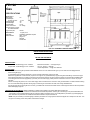
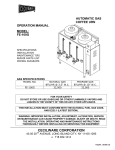
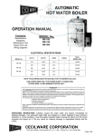
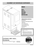
FE100G
Automatic Coffee Urn
OPERATION MANUAL
Contents
SPECIFICATIONS
INSTALLATION
ADJUSTMENTS
OPERATING INSTRUCTIONS
MAINTENANCE TIPS PARTS LIST
ILLUSTRATIONS WIRING
DIAGRAMS
FOR YOUR SAFETY
DO NOT STORE OR USE GASOLINE OR OTHER FLAMMABLE VAPORS AND
LIQUIDS IN THE VICINITY OF THIS OR ANY OTHER APPLIANCE.
THIS INSTALLATION MUST CONFORM WITH THE NATIONAL
FUEL GAS CODE ANSI Z223.1 (Latest Edition).
WARNING: IMPROPER INSTALLATION, ADJUSTMENT, ALTERATION OR
MAINTENANCE CAN CAUSE PROPERTY DAMAGE. INJURY OR DEATH.
READ THE INSTALLATION. OPERATION AND MAINTENANCE
INSTRUCTIONS THOROUGHLY BEFORE INSTALLING
OR SERVICING THIS EQUIPMENT.
WARRANTY
Every Ceclware product has been carefully inspected before shipment. The finest of materials and the highest
standards of workmanship have been but into the equipment.
Within 1 year of purchase, should any Cecilware product show defect in factory workmanship or material, we agree to
Repair, at our option or replace without cost to user such parts which prove upon factory inspection to have been so
defective. All equipment must be shipped transportation charges prepaid for acceptance. This warranty covers
replacement parts only, labor charges are covered for 90 days after installation.
This warranty does not apply under the following conditions:
• neglect or abuse of equipment
• excessive lime condition
• Improper installation
• any outside modification to equipment
Every Cecilware urn body is covered for three years. This warranty covers the stainless steel body
and stainless steel liners only.
Portable equipment such as Electric Fryers, Food Warmers, Electric Stoves, Dispensers, Plug-In
Urns, Coffee Brewers and Warmers must be returned to the factory or brought to an authorized
service station for repair.
CECILWARE CORPORATION
43-05 20th Avenue, Long Island City, N.Y. 11105 • 718-932-1414
N529A-4/92
FOR YOUR SAFETY
DO NOT STORE OR USE GASOLINE OR OTHER
FLAMMABLE VAPORS AND LIQUIDS IN THE
VICINITY OF THIS OR ANY OTHER APPLIANCE.
SAFETY PRECAUTIONS
FOR YOUR SAFETY, THE FOLLOWING SAFETY PRECAUTIONS
SHOULD BE FOLLOWED AND ENFORCED.
1. Instructions must be posted in a prominent location and all safety precautions taken in the event the
user smells gas. Obtain this information from your local gas supplier.
IF YOU SMELL GAS:
1. OPEN WINDOWS
2. DON'T TOUCH ELECTRICAL SWITCHES
3. EXTINGUISH ANY OPEN FLAMES
4. IMMEDIATELY CALL YOUR GAS SUPPLIER
2. Lighting - Follow instructions on label attached to side of urn, or see page 2.
3. This appliance is equipped with a three prong (grounding) plug for your protection against shock hazard and
should be plugged directly into a properly grounded three-prong receptacle. Do not cut or remove the grounding
prong from this plug.
4. A wiring diagram of the control is located on the inside of the removable control box panel.
5. Do not place anything over the flue opening.
6. Do not place combustibles or non-combustible materials in the vicinity of the urn as this could cause fires or
obstruct air to the main burners.
7. This installation must conform with local codes, or in the absence of local codes, with the National Fuel Gas
Code ANSI Z223.1 latest edition.
8. Provide adequate air supply and ventilation.
9. Provide adequate clearance for air openings into the combustion chamber.
10. Provide clearances for servicing and proper operation.
11. This appliance must be electrically grounded in accordance with local codes, or in the absence of local codes,
with the National Electrical Code ANSI/NF PA No. 70 latest edition.
12. FOR USE ON NON-COMBUSTIBLE FLOORS - MINIMUM CLEARANCE FROM COMBUSTIBLE
CONSTRUCTION 6" FROM SIDE - 8" FROM BACK.
13. Urn must be disconnected from gas supply during any pressure testing of pipelines in excess of 1/2 psig, and
isolated (by turning off manual gas shut-off valve) during any testing equal to or less than 1/2 psig.
14. Retain this manual for future reference.
1
FE-100
Gas
SPECIFICATIONS
Dimensions
Body Depth
16"
Overall Depth
to faucet centers:
19 1/2"
Working Height
26"
Overall Height:
31"
Overall Width:
37 1/2"
Water Connection:
1/4" tubing
Constructed of type 304,
18-8 Stainless Steel
Approx Ship Wt;
125 Ibs.
Performance
Gas Data
Electrical Data
15 gals. per hr.
32,000 BTU. Natural & Propane
120V. 3 amps
plug-in for
electrical
accessories
Note: Use TOSSAWAY- PAPER FILTERS No. 718
INSTALLATION INSTRUCTIONS
FE-100G GAS AUTOMATIC
SPECIFICATIONS:
Natural Gas - 32,000 BTU @ 4" W.C. Pressure
Propane Gas- 32,000 BTU @ 10" W.C. Pressure
Electrical Connections — Cord Type Plug-in
120 Vac, 15 Amp — 50/60 Hz
Power Requirement — 3A @ 120V 50/60 Hz
INSTALLATION:
CAUTION: Examine the gas specifications label attached to the urn to be certain that the type of I ) JS for which the unit is equipped is the
same as the gas supply.
It is essential to leave a minimum clearance of 6" from the side walls and 8" from the rear wall.
Machine is supplied with a water strainer (23) and a 19" length of 1/4" (outside diameter) copper tubing with a flare fitting. Connect the copper
tubing with the flare fitting to the water connection at the rear of the machine. The other end of the strainer is connected with a suitable length
of '/4" tubing and shut off valve (supplied by a plumber) to a cold water supply. Water pressure should be a minimum of 20 Ibs. for proper
operation.
Before connecting the gas line, turn on the water supply valve and insert the line cord into a 120V grounded outlet. The water will start entering
the urn and the water filling operation will be going on while the gas connections are made, thus saving installation time.
Connect the 3/8" gas line to the gas shut-off valve (1) located at the rear of the thermostat control. Check all gas connections with soap solution
before attempting to light urn.
LIGHTING AND ADJUSTMENTS - (Refer to Illustration 1) Water must be visible in the gauge glass before lighting pilot.
Turn on the main gas valve and set the thermostat dial to the desired temperature. Turn the gas cock valve (9) on top of the thermostat to the
"pilot" position. Insert a lighted match through the opening located on the bottom of the urn and depress the pilot button (10) while lighting the
pilot. Hold down the pilot button for at least 30 seconds and release. The pilot will remain lit.
NOTE: It may be necessary on the first lighting to hold the pilot button for a longer period to allow the trapped air to escape from the lines. Turn
the gas cock valve (9) to the "ON" position and the burner will light.
2
RELIGHTING: Shut off all gas and wait 5 minutes before relighting pilot.
SHUTTING DOWN: To shut down urn completely, turn gas cock knob to "OFF" and main gas valve off.
Gas and thermostat adjustments are set at the factory, however, due to different gas conditions, it may be necessary to
make minor burner adjustments. The gas orifices are fixed and the proper flame adjustment is obtained by adjusting the
air shutters which are accessible from the opening in the bottom of the urn.
In case of prolonged power failure, turn gas cock valve to "pilot" position. When power
supply resumes, turn gas cock valve to "ON" position.
For all other adjustments and maintenance procedures, refer to the urn text.
PARTS LIST FOR FE-100 GAS
Item No.
1
2
2a
3
4
4a
5
5a
6
7
8
FE-100 GAS URN
ILLUSTRATION 1
Description
Gas valve
Pressure regulator (nat. gas)
Pressure regulator (prop gas}
Thermostat
Nat. Pilot thermocouple set
Prop. Pilot thermocouple set
Nat. Orifice
Prop, Orifice
Burner
Manifold
Thermocouple
Part No.
F008A
L043A
L198A
L024A
F047A
F048A
F098A
F126A
G090Q
F044A
F002A
Correct Procedures for Brewing Coffee
As Recommended by the Coffee Brewing Center
1. Use fresh urn or drip grind coffee - - - spread evenly as an even coffee bed is important for proper extraction.
2. Urn should be connected to cold water supply and the water heated sufficiently to insure brewing temperatures of 195°-2050F.(900-96°C).
Leave cover on urn during brewing. Total contact time for urn grind should be approximately 4-6 minutes.
3. Remove grounds and filter basket immediately after water has dripped through.
4. If automatic agitation is not incorporated, mix brew by drawing off heavy coffee from bottom of batch and pouring back into brew.
Mix at least one gallon per pound of coffee used.
5. Never repour brewed coffee back through spent grounds.
6. Hold coffee at 185°-190°F (85°-88°C) for proper serving temperature. Brewed coffee should not be held for longer than one (1) hour; it
should never be reheated if allowed to cool, and it should never be boiled.
Par. 2. TIMER:
An electronic solid state timer is used to control the volume of water for brewing the coffee. The timers are pro-set at the factory to deliver Vh
gallons of water for each brewing cycle.
However, if other volumes of water are desired, or a correction is necessary, follow these instructions:
To increase the volume of water, turn the timer knob clockwise (see illustration 2). To decrease the volume of water, turn the knob counterclockwise. Run through a complete cycle for each setting. Note that the timer cannot be readjusted once it is activated. To terminate the cycle
if the liner overflows, simply activate the cycle stop switch at the bottom of the side box. If the maximum setting of the timer fails to deliver
enough water, check the water pump and spray head and follow instructions under maintenance.
Par. 2a. SPRAY ARM BY-PASS ADJUSTMENTS:
Urns equipped with an adjustable by-pass are delivered from the factory with the by-pass adjusted. If further by-pass adjustments are required
to correct local water conditions, proceed as follows:
Place the spray head over the center of the right coffee liner and activate the brew cycle switch. Insert a screwdriver in the by-pass adjustment
slot and turn it counter-clockwise to increase or clockwise to decrease by -pass flow. At the completion of the brewing cycle, measure the
volume of the water in the coffee liner. The timer may have to be re-adjusted to obtain the correct volume of water. The proper setting of the
by-pass will have to be determined by
the user.
3
Par. 3 THERMOSTAT: To adjust the temperature of the water in the urn (205°F) or (96°C), turn the thermostat knob to its
maximum counter-clockwise position. Remove the knob by pulling it toward you. Hold STOP while nut is loosened, taking
care not to move temperature adjusting screw. When the indicator of the temperature approaches the "W" in the word
BREW, slowly rotate the thermostat shaft until the burner flame goes out. Turning the shaft clockwise lowers the
temperature and conversely counter-clockwise raises it. Locate stop against stop pin and tighten nut-replacing knob.
MAINTENANCE TIPS
Par. 4. WATER CONDITION:
Remove and clean spray head cap and spray head disc frequently - typically once a week. (See illustration 3.) To clean swivel valve,
loosen nut and remove spray arm assembly from urn. Sediment may be removed by inserting a pipe cleaner through small hole in valve. If
maximum setting of timer fails to deliver enough water, check water pump (28).
Par. 4a OUTSIDE SERVICE: Should you require help contact the factory, your factory representative, or your local service company.
FOR QUALIFIED SERVICE PERSONS ONLY
When servicing of unit is required, contact a qualified service agency.
CAUTION: DO NOT TURN ON THERMOSTAT BEFORE ALL PRIMING INSTRUCTIONS ARE COMPLETED.
Par. 8. WATER FROM COLD WATER SUPPLY LINE DOES NOT ENTER URN. (Refer to illustration 2)
1. Check water supply to shut-off valve and strainer.
2. Check fuse (30) on front panel and replace with proper fuse if necessary.
3. If steps 1 and 2 are in order, remove fuse and lift outside panel from urn.
4. Remove two screws from timer panel and remove timer exposing terminal strip (III. 4) and electrical wiring.
5. Replace fuse.
6. Place wire jumper across terminals (8) and (9) on terminal board (III. 4). If water enters urn, float switch is
inoperative and should be replaced as explained in Par. 10. If water does not enter urn, then solenoid valve (27) or small relay (14) is
not functioning. To check solenoid valve, disconnect leads from the coil and apply 115V power. If solenoid operates, replace relay.
Par. 9. REPLACING SOLENOID VALVE:
1. Shut off water supply and remove fuse (30) from front panel.
2. Disconnect wires from terminals on solenoid coil.
3. Remove flare nut from solenoid valve and unscrew solenoid valve from bracket.
4. Install new unit.
Par. 10. REPLACING FLOAT SWITCH:
1. Remove fuse (30) from front panel.
2. Remove screws from timer panel and remove timer exposing terminal board and electrical wiring.
3. Disconnect wires from terminals (8) and (9) on terminal board and release float switch wires. (See III. 4).
4. Unscrew packing nut from bottom of float mechanism and remove cartridge (17)by pulling on the wires.
5. Replace with new cartridge and assemble unit and wiring in reverse order.
CLEANING FLOAT CONTAINER:
Periodically it may become necessary to clean out float container(13)in order to keep float switch in proper operating condition,
1. Remove float can cover (10) from top of control box exposing ball float (9) and stem.
2. Lift ball from stem.
3. Clean container and all parts and reassemble unit.
4. Replace cover.
Par. 11. AUTOMATIC REFILL OVERFLOWS:
Remove fuse (30) from front panel, water should cease flowing which indicates float switch is inoperative. However, if water still continues to
flow, valve in solenoid is lodged or dirty and should be replaced.
Follow instructions in Par. 9 or 10.
Par. 12. NO WATER FROM SPRAY HEAD:
1. Check panel fuse (30) first.
2. a. Depress BREW button (29) and note if pilot light remains lit when button is released. If pilot light stays on,
we can assume water pump is not operating. Remove side panel and check if fan on water pump is not rotating;
then pump should be replaced as in Par. 13
4
Par. 13. REPLACING WATER PUMP:
1. Turn off water and electrical power from urn.
2. Drain urn to level of center faucet.
3. Open the control box and disconnect the two pump wires from the quick disconnect terminals.
4. Loosen union fittings on pump and remove pump from urn.
5. Replace pump and follow priming instructions.
Note: Pump and motor assembly are factory lubricated for the life of the pump.
Par. 14. TIMER-SOLID STATE:
Depress BREW button and hold for approximately 10 seconds and then release. If w ater flows from spray head when button is depressed and
stops flowing after button is released, then timer is faulty and should be replaced. No water from spray head when button is depressed,
indicates BREW button is at fault and must be replaced.
AGITATOR
OPERATION:
The agitator pump circuit is programmed to operate when the brew button is pushed. Upon completion of the pump cycle, the agitator pump
will pump air through the manifold into the coffee gauge glasses and into the coffee liner. The completed cycle will take approximately 20
seconds. The agitator may be operated independently of the brewing cycle, if the agitator button is depressed.
MAINTENANCE:
The air pump is capable of delivering enough air for proper blending. However, if enough agitation is not present, check flexible tubing on top
of gauge glasses, gauge glasses and fittings, for possible air leaks. If air pump does not operate on completion of brewing cycle or when
agitation button is depressed, replace air pump or solid state agitator timer (black box).
BURNER MAINTENANCE:
The two main burners can be removed by first removing the base cover panel and unfastening the burner ends. The main burners should be
cleaned both inside the venturi portion and on the outside using a soft bristle brush. The main burners must be replaced into the same position
as prior to removal. Once a year, a qualified service agency should be contacted to inspect the appliance for safe and proper operation.
PARTS LIST
ITEM NO.
STOCK
NO.
PARTS LIST
DESCRIPTION
1
2
E045A
U019A
Complete spray assm, w/bypass
Vent cap drain
3
4
5
6
7
7
8
9
10
11
12
13
14
15
16
17
18
18
19
20
Q024A
E023A
H050A
C511A
U152A
L249A
L238A
E040A
U022A
V002A
Q082Q
U023Q
L018A
C008A
B034A
L019A
L205A
L210A
B039A
BOOOA
Cover with knob
3" Nipple union assembly
9 ½” Agitator tubing
Agitator pump assembly
Agitator box cover
Agitator assm. (solid state aut.)
Solid state agitator timer
Float
Float can cover
Brew basket (s/s)
Liner - 3 gallon
Float can assembly
Relay
Capacitor & resistor assm.
Terminal block
Float switch
Solid state timer 120V
Solid state timer 220V
Grounding lug
Terminal Block
22
K028A
Elbow
23
24
25
25
E002A
H016Q
C396A
C142A
Water strainer
19" Copper tubing
Fuse holder, SC -6 type
Fuse holder, FN type (Canadian)
26
L017A
Cycle stop switch
ITEM NO.
5
STOCK
NO.
DESCRIPTION
27
27
27
27
28
28
28
28
28
29
30
30
31
32
L022A
X008A
X033A
X035A
EOOOA
EOOOT
U070A
E069A
X032A
L012A
C395A
C141A
L236A
L007A
Solenoid .35 GPM
Solenoid coil
Solenoid diaphragm repair kit
Solenoid flow washer (Not shown)
G-water pump
Rebuilt G-water pump
G-water pump fan
H-water pump
Seal kit for G-water pump
BREW switch
Fuse 6A SC -6
Fuse. 5AFN (Canadian)
Agitator switch
Dial thermometer
35
D021A
Shank for coffee gauge
36
37
38
39
40
40
D017A
X005A
M005S
D022A
E009A
E071A
Water and coffee faucet
Coffee gauge glass
Legs, chrome
Shank for water gauge
Overflow drain
Overflow drain
41
42
43
44
45
46
X006A
D024A
D001A
H051A
H025Q
K108A
Water gauge glass
8" or 8'/2 -Water gauge shield
9" Coffee gauge shield
5" Agitator Tubing
Overflow tube
Vent cap assembly
718
Filter pack (Not shown)
Illustration 2
(FE 100 GAS Shown)
SPRAY ARM ASSEMBLY
This new improved spray head system was designed to facilitate easier cleaning and maintenance
The swivel valve has a greater flow opening and the spray head cap is equipped with a stainless steel disc used to control the flow of
water. This enables the operator to clean the spray system at the spray cap disc instead of re moving the complete swivel with
assembly.
It is necessary to use the correct disc and spray cap with each coffee urn.
Adjustable by-pass is standard equipment on Cecilware coffee urns models FE-75, - 100, - 250, - 300, - CRS-66 and 100G
6
6
FE-100 G WIRING & SCHEMATIC DIAGRAMS