1
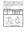
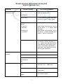
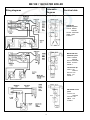
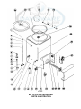
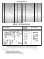
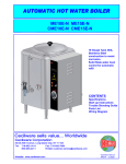
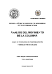
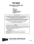
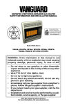
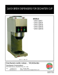
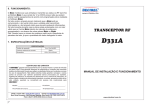
AUTOMATIC
HOT WATER BOILER
OPERATION MANUAL
Contents
MODEL No.
Specifications
Installation
Maintenance Tips
Repair Parts List
Wiring Diagrams
ME-10E
ME-15E
ME-30E
ELECTRICAL SPECIFICATIONS
VOLTS
WATTS
AMPS
PHASE
FIELD
WIRING SIZE
120
1,800
15.0
1
14AWG
240
7,000
29.2
1
10AWG
ME-15E
208
5,300
25.5
1
10AWG
ME-30E
240
10,500
25.0
3
10AWG
208
7,900
22.0
3
10AWG
MODEL No.
ME-10E
NOTE: FIELD WIRING MUST BE SUITABLE FOR 75 DEGREES CELCIUS.
USE COPPER WIRE ONLY FOR POWER SUPPLY CONNECTION.
COPPER WIRE: 14 AWG MINIMUM COPPER ONLY.
WARRANTY
Every Cecilware product has been carefully inspected before shipment. The finest of materials and the highest
standards of workmanship have been but into the equipment.
Within 1 year of purchase, should any Cecilware product show defect in factory workmanship or material, we agree to
Repair, at our option or replace without cost to user such parts which prove upon factory inspection to have been so
defective. All equipment must be shipped transportation charges prepaid for acceptance. This warranty covers
replacement parts only, labor charges are covered for 90 days after installation.
This warranty does not apply under the following conditions:
• neglect or abuse of equipment
• excessive lime condition
• Improper installation
• any outside modification to equipment
Every Cecilware urn body is covered for three years. This warranty covers the stainless steel body and stainless steel
liners only.
Portable equipment such as Electric Fryers, Food Warmers, Electric Stoves, Dispensers, Plug-In Urns, Coffee
Brewers and Warmers must be returned to the factory or brought to an authorized service station for repair.
UNPACKING INSTRUCTION: Carefully unpack the water boiler and inspect immediately for
shipping damages. Your automatic water boiler was shipped in a carton designed to give maximum
protection in normal handling. It was thoroughly inspected before leaving the factory and the carrier
accepted and signed for it. File any claims for shipping damage or irregularities directly with the
carrier.
CECILWARE CORPORATION
43-05 20th AVENUE, LONG ISLAND CITY, N.Y. 11105 • 718-932-1414 • FAX 718-932-7860
N796A-10/98
ASSEMBLY: The four legs, faucet, float ball, and vent cap drain are packed
separately with the water boiler. Install legs by tilting the water boiler on its side
and screwing the legs into the leg supports until hand tight Carefully right the unit
and install it in its permanent location, being sure to leave at lest 6" on the right
side of the water boiler for access to the controls. Level the unit by adjusting the
bottom pad of the legs. Screw the ball float (36) onto the end of the water inlet
valve rod (35). Place the vent cap (30) into the recess in the top of the unit. Mount
the faucet assembly onto the shank (13).
GENERAL SPECIFICATIONS
DIMENSIONS (INCH)
WATER CAP. IN
GALLONS
A
B
C
D
SHIPP.
WT.(LB)
ME-10E
10.0
14
16
22.5
25.5
45
ME-15E
15.0
14
16
27.5
30.5
50
ME-30E
30.0
29
14
22.5
25.5
95
MODEL NO.
2
CECILWARE CORPORATION
INSTALLATION INSTRUCTION FOR WATER BOILERS
Water boilers are shipped with the thermostats in the OFF position. Do not turn the thermostat
on before filling the water boiler with water.
NOTE: When positioning the unit, leave a minimum of 6" clearance on the right side of the
water boiler for ease of service.
WATER HOOK-UP PROCEDURE:
Use ¼” outside diameter copper tubing to connect the unit to the water supply line. The water
line must have a shut-off valve (supplied by a plumber). At the unit, connect the tubing to the
compression water inlet valve at the upper right hand side of the unit.
NOTE: Connecting the water boiler to a warm water supply will speed up heating and
recovery times.
ELECTRICAL HOOK-UP PROCEDURES:
NOTE: Always check the rating plate of the unit for proper voltage and current requirements.
1. 120V water boilers are provided with a 120V/15A grounded plug. Units must have a
separate 120V/15A outlet.
2. 208/240V water boilers are provided with a terminal block inside the control box. Field
wiring must be performed by a qualified serviceman.
1 and 3 phase hook-up:
Remove the fasteners on the cover and slide off cover. Install a suitable conduit and
connect copper wires to terminal L1 and L2 (and L3 for 3 phase unit only) and a #14
AWG ground wire to the ground lug.
PRIMING AND FILLING A UNIT:
Connect unit to power line (plug cord into line for 120V unit or turn on switch for the 208/ 240V
units). Turn on the water supply. The unit fills at the rate of 1 gallon/minute. When the water
level becomes visible in the sight gage turn the thermostat clockwise to maximum position.
The unit will now automatically fill to capacity and heat the water.
CLEANING INSTRUCTIONS:
DAILY: Wipe the outside of the unit with a damp cloth, using soap solution or a non-abrasive
compound when required.
SANITIZING THE UNIT:
With power to the unit disconnected, fill unit to capacity. Add 1 ounce of CLOROX BLEACH
(5.25%) for every gallon of water in the unit (400 PPM). Let the solution stand in the unit for 15
minutes, then drain all water from the unit slowly. If the unit is not to be used again
immediately after sanitizing — do not rinse with water. If the unit is to be used immediately
after sanitizing — rinse with water before refilling the unit for further use.
3
SERVICE PROCEDURES
FOR QUALIFIED SERVICE PERSONNEL ONLY
TO REPLACE HEATING ELEMENT
1. Shut off electrical power to unit.
2. Shut off water supply to unit.
3. Drain water from unit by tilting the unit toward at the end of the drain cycle.
4. Remove control box cover and disconnect electric wire from electrical connection to the
heating element(s).
5. Remove (4) screws and pull out heating element(s) with gasket.
6. Install new heating element(s) with gasket.
7. Connect electrical wires to elements).
8. Repeat priming instructions.
TO REPLACE THERMOSTAT
1. Shut off electrical power to unit.
2. Remove control box cover and thermostat knob.
3. Disconnect electrical wires from thermostat.
4. Loosen small capillary nut, then the packing nut from boiler.
5. Remove (2) screws holding thermostat to side box.
6. Remove thermostat and pull out thermostat bulb from boiler. Note position of compression
ring on capillary tube.
7. Install new thermostat. Position capillary end of thermostat bulb two (2) inches from inside
wall.
8. Tighten large packing nut, then small capillary nut — DO NOT over tighten since this could
damage the controls.
9. Remount thermostat to control box side.
10. Re-connect electrical wires to thermostat.
11. Replace thermostat knob.
12. Repeat priming instruction.
13. Recalibrate control if required. Water temperature should be 195 to 205 degree F
maximum.
TO REPLACE HI-LIMIT CONTROL
1. Shut off electrical power to unit.
2. Remove control box cover and disconnect (4) electrical wires form control.
3. Loosen and remove (2) retaining nuts.
4. Install new control in reverse order.
REPLACING WATER INLET CONTROL VALVE
1. Shut off water supply to unit.
2. Disconnect water line from control valve.
3. Unscrew floatball.
4. Remove hex nut and washer while holding the valve/float arm assembly with the other
hand.
5. Install replacement valve in reverse order.
REPLACING FLOATBALL
1. Shut off water supply to unit.
2. Unscrew float ball. Check for water leaks by shaking the ball.
3. Replace defective float ball.
4
TROUBLE SHOOTING PROCEDURES FOR QUALIFIED
SERVICE PERSONNEL ONLY
PROBLEM
Water fails to heat
POSSIBLE CAUSES
Line Fuse
or
SOLUTIONS OR REMEDIES
Check for circuit overload before resetting
breaker or replacing fuse.
Circuit Breaker
Hi-Limit Switch
If Hi-Limit switch opens when water temp.
reaches 200 degree F, replace switch.
No voltage reading at
element
a. Defective
thermostat
Check voltage across terminals 1 and 3 of
Hi-Limit switch. If no reading replace
thermostat.
b. Defective HiLimit switch
Water does not
stop filling
Check voltage across terminals 2 and 4. If
no reading — depress red button. Still no
reading — replace Hi-Limit switch.
Thermostat
Pilot light should be on when thermostat
is in the full on position (#5 position). If
not — replace thermostat and recalibrate
(see calibration). Power supply should
meet or exceed power requirements of
water boiler. Check data label on control
box for power requirements.
Stuck valve
Replace valve
Worn valve seat
Replace valve
Float ball filled
Replace float ball
with water due to
leak
Water does not fill
Stuck filling
Check float ball. It should move easily up
and down. If not — replace valve.
valve
Hung up float
If float ball linkage does not move freely,
replace valve
Water line
clogged
Shut off water supply. Disconnect inlet
line. Clean or replace.
5
ME 10E / 15E WATER BOILER
Wiring diagrams
Schematic
diagrams
Electrical data
ME10E/15E
208/240 V/3 phase
VOLTS: 208/240
50/60 HZ
WATTS: 7900/10500
AMPS: 22/25
PHASE: 3
ME10E/15E 120V
208/240 V/1 phase
VOLTS: 208/240
50/60 HZ
WATTS: 5300/7000
AMPS: 25.5/29.2
PHASE: 1
120 Volt Hook Up
VOLTS: 120
50/60 HZ
WATTS: 1750
AMPS: 14.6
PHASE: 1
ME10E/15E 120 V/1
phase
VOLTS: 120
50/60 HZ
WATTS: 1750
AMPS: 14.6
PHASE: 1
6
J11.1
ME 10/15 E WATER BOILER
PARTS ILLUSTRATION
7
PARTS LIST ME 10/15E
No.
Description
ME-10E
ME-15E
No.
Description
ME-10E
ME-15E
1
Gauge Shield Mounting Bracket
U160A
U160A
20
Thermostat Bezel
M016A
M016A
2
Vent Cap Assembly
K108A
K108A
21
Control Box
R484A
R484A
3
Gauge Shield Washer KH
X012A
X012A
22A
High-Limit Control 120V
L224A
L224A
4
Water Gauge Glass
X030A
X043A
22B
High-Limit Control 240V
M0602
M0602
5
Water Gauge Shield
D020A
D031A
23
Flange
U013A
U103A
6
Handle
X007A
X007A
24
Heater Gasket
M0680
M0680
7
Plastic Bonnet
X010A
X010A
25A
Heater 120V
G199A
G199A
8
Faucet Spring, S.S.
X019A
X019A
25B
Heater 240V
G197A
G197A
9
Stem
X058A
X058A
26
Control Box Cover
R485A
R485A
10
Cup Seat
X014A
X014A
27
Thermostat
L029A
L029A
11
Silicon Gasket
M256A
M256A
28
Terminal Block
BOOOA
BOOOA
12
Faucet Assembly
0017A
D017A
29
Overflow Tube
H084Q
H059Q
13
Shank
D021A
D021A
30
Vent Cap Drain
U019A
U019A
14
Dial Thermometer
L007A
L007A
34
Stem Valve
M0251
M0251
15
Chrome Plated Nut, %" NPT
K110A
K110A
35
Adapter, % - 20
M0589
M0589
16
Body
R479A
R480A
36
S.S. Float, 3"
M0892
M0892
17
Legs,set of 4
M005S
M005S
37
Knob
M027A
M027A
18
Overflow Drain
E071A
E071A
38
Cover
Q102H
Q102H
19
Thermostat Knob
M008A
M008A
ME 10E / 15E WATER BOILER
Schematic
diagrams
Wiring diagrams
Electrical data
ME 10E/15E 120V
208/240 V/1 phase
VOLTS: 208/240
50/60 HZ
WATTS: 5300/7000
AMPS: 25.5/29.2
PHASE: 1
120 Volt Hook Up
VOLTS: 120
50/60 HZ
WATTS: 1750
AMPS: 14.6
PHASE: 1
CONVERSION INSTRUCTIONS FOR ME-10E and ME-15E WATER BOILERS
Conversion from 208 volts or 240 volts to 120 volts
To convert to 120 volt 15 amp outlet application simply connect a 120 volt 15 amp line cord equipped with 2 prong grounding cap to
terminal as follows.
1.
2.
3.
4.
5.
Connect white lead to terminal block marked (L1).
Connect black lead to terminal block marked (L2).
Connect green lead to copper ground terminal marked GND.
Secure cord to terminal box with a strain relief clamp.
Change Marketings on Rating Label to reflect the voltage change.
8