1
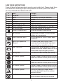
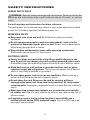
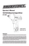
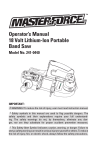
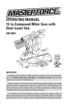
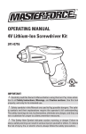
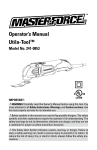
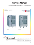
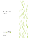
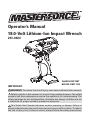
Operator’s Manual 18.0-Volt Lithium-Ion Impact Wrench 241-0424 IMPORTANT : CHARGE BATTERY BEFORE FIRST USE WARNING! To reduce the risk of injury, user must read instruction manual. Safety symbols in this manual are used to flag possible dangers. The safety symbols and their explanations require the operator’s full understanding. The safety warnings do not, by themselves, eliminate any danger, and they are not a substitute for proper accident prevention measures. This Safety Alert Symbol indicates caution, warning, or danger. Failure to obey a safety warning can result in serious injury to yourself or others. To reduce the risk of injury, fire, or electric shock, always follow the safety precautions. TABLE OF CONTENTS Safety Symbols................................................................................................ Page 3 Safety Instructions......................................................................................... Page 5 Description....................................................................................................... Page 9 Assembly.......................................................................................................... Page 10 Operation.......................................................................................................... Page 11 Maintenance................................................................................................... Page 14 Troubleshooting............................................................................................... Page 14 Warranty........................................................................................................... Page 15 INTRODUCTION SAVE THESE INSTRUCTIONS! This cordless Impact Wrench has many features for making its use more pleasant and enjoyable. Safety, performance, and dependability have been given top priority in the design of this product making it easy to maintain and operate. 2 SAFETY SYMBOLS The purpose of safety symbols is to attract your attention to possible dangers. The safety symbols and the explanations with them deserve your careful attention and understanding. The symbol warnings do not, by themselves, eliminate any danger. The instructions and warnings they give are no substitutes for proper accident prevention measures. WARNING! Be sure to read and understand all safety instructions in this manual, including all safety alert symbols such as “DANGER,” ”WARNING,” and “CAUTION” before using this impact wrench. Failure to following all instructions listed below may result in electric shock, fire, and/or serious personal injury. SYMBOL SIGNAL DANGER! MEANING Indicates an imminently hazardous situation, which, if not avoided, will result in death or serious injury. WARNING! Indicates a potentially hazardous situation, which, if not avoided, could result in death or serious injury. CAUTION! Indicates a potentially hazardous situation, which, if not avoided, could result in minor or moderate injury. NOTE: (Without Safety Alert Symbol) Indicates a situation that may result in property damage. WARNING! To ensure safety and reliability, all repairs should be performed by a qualified service technician at an Authorized Service Center. WARNING! The operation of any power tool can result in foreign objects being thrown into your eyes, which can result in severe eye damage. Before beginning power tool operation, always wear safety goggles or safety glasses with side shields and a full-face shield when needed. We recommend a Wide Vision Safety Mask for use over eyeglasses or standard safety glasses with side shields. Always use eye protection which is marked to comply with ANSI Z87.1 3 SAVE THESE INSTRUCTIONS Some of these following symbols may be used on this tool. Please study them and learn their meaning. Proper interpretation of these symbols will allow you to operate the tool better and safer. V A Hz W min .../min Volts Amperes Hertz Watt Minutes Alternating Current Voltage Current Frequency (cycles per second) Power Time Type of current Direct Current No Load Speed Type or a characteristic of current Rotational speed, at no load Class II Construction Double-insulated construction Per Minute Revolutions, strokes, surface speed, orbits, etc., per minute Do not expose to rain or use in damp locations. Wet Conditions Alert Read The Operator’s Manual Eye Protection Safety Alert To reduce the risk of injury, user must read and understand operator’s manual before using this product. Always wear safety goggles or safety glasses with side shields and a full face shield when operating this product. Precautions that involve your safety. No Hands Symbol Failure to keep your hands away from the blade will result in serious personal injury. No Hands Symbol Failure to keep your hands away from the blade will result in serious personal injury. No Hands Symbol Failure to keep your hands away from the blade will result in serious personal injury. No Hands Symbol Failure to keep your hands away from the blade will result in serious personal injury. To reduce the risk of injury or damage, avoid contact with any hot surface. Hot Surface 4 SAFETY INSTRUCTIONS GENRAL SAFETY RULES WARNING! Read all safety warnings and instructions. Failure to follow the warnings and instructions may result in electric shock, fire and / or serious injury. Save all warnings and instructions for future reference. The term power tool in the warnings refers to your mains-operated (corded) power tool or battery-operated (cordless) power tool. Work area safety eep work area clean and well lit. Cluttered or dark areas invite K accidents. o not operate power tools in explosive atmospheres, such as in the D presence of flammable liquids, gases or dust. Power tools create sparks which may ignite the dust or fumes. eep children and bystanders away while operating a power tool. K Distractions can cause you to lose control. Electrical safety ower tool plugs must match the outlet. Never modify the plug in any P way. Do not use any adapter plugs with earthed (grounded) power tools. Unmodified plugs and matching outlets will reduce risk of electric shock. void body contact with earthed or grounded surfaces such as pipes, A radiators, ranges and refrigerators. There is an increased risk of electric shock if your body is earthed or grounded. o not expose power tools to rain or wet conditions. Water entering a D power tool will increase the risk of electric shock. o not abuse the cord. Never use the cord for carrying, pulling or D unplugging the power tool. Keep cord away from heat, oil, sharp edges or moving parts. Damaged or entangled cords increase the risk of electric shock. hen operating a power tool outdoors, use an extension cord suitable W for outdoor use. Use of a cord suitable for outdoor use reduces the risk of electric shock. I f operating a power tool in a damp location is unavoidable, use a residual current device (RCD) protected supply. Use of an RCD reduces the risk of electric shock. 5 Personal safety tay alert, watch what you are doing and use common sense when S operating a power tool. Do not use tool while tired or under the influence of drugs, alcohol, or medication. A moment of inattention while operating power tools may result in serious personal injury. se personal protective equipment. Always wear eye protection. Protective U equipment such as dust mask, non-skid safety shoes, hard hat, or hearing protection used for appropriate conditions will reduce personal injuries. revent unintentional starting. Ensure the switch is in the off-position P before connecting to power source and / or battery pack, picking up or carrying the tool. Carrying power tools with your finger on the switch or energizing in power tools that have the switch on invites accidents. emove any adjusting key or wrench before turning the power tool on. R A wrench or a key left attached to a rotating part of the power tool may result in personal injury. o not overreach. Keep proper footing and balance at all times. This D enables better control of the power tool in unexpected situations. ress properly. Do not wear loose clothing or jewelry. Keep your hair, D clothing and gloves away from moving parts. Loose clothes, jewelry or long hair can be caught in moving parts. I f devices are provided for the connection of dust extraction and collection facilities, ensure these are connected and properly used. Use of these devices can reduce dust-related hazards. 4) Power tool use and care o not force the power tool. Use the correct power tool for your D application. The correct power tool will do the job better and safer at the rate for which it was designed. o not use the power tool if the switch does not turn it on and off. Any D power tool that cannot be controlled with the switch is dangerous and must be repaired. isconnect the plug from the power source and/or the battery pack from D the power tool before marking any adjustments, changing accessories, or storing power tools. Such preventive safety measures reduce the risk of starting the power tool accidentally. tore idle power tools out of the reach of children and do not allow persons S unfamiliar with the power tool or these instructions to operate the power tool. Power tools are dangerous in the hands of untrained users. aintain power tools. Check for misalignment or binding of moving M parts, breakage of parts and any other condition that may affect the power tool’s operation. If damaged, have the power tool repaired before use. Many accidents are caused by poorly maintained power tools. 6 eep cutting tools sharp and clean. Properly maintained cutting tools with K sharp cutting edges are less likely to bind and are easier to control. se the power tool, accessories and tool bits etc., in accordance with U these instructions, taking into account the working conditions and the work to be performed. Use of the power tool for operations different from those intended could result in a hazardous situation. 5) Battery tool use and care echarge only with the charger specified by the manufacturer. A charger R that is suitable for one type of battery pack may create a risk of fire when used with another battery pack. se power tools only with specifically designated battery packs. Use of U any other battery packs may create a risk of injury and fire. hen battery pack is not in use, keep it away from other metal objects, W like paper clips, coins, keys, nails, screws or other small metal objects that can make a connection from one terminal to another. Shorting the battery terminals together may cause burns or a fire. nder abusive conditions, liquid may be ejected from the battery; U avoid contact. If contact accidentally occurs, flush with water. If liquid contacts eyes, additionally seek medical help. Liquid ejected from the battery may cause irritation or burns. 6) Service ave your power tool serviced by a qualified repair person using only H identical replacement parts. This will ensure that the safety of the power tool is maintained. SPECIFIC SAFETY RULES FOR CORDLESS IMPACT WRENCH Use battery only with charger listed. Battery pack 252-8024 252-8028 252-8032 Charger 252-8036 old power tools by insulated gripping surfaces when performing an H operation where the cutting tool may contact hidden wiring. Contact with a “live” wire will make exposed metal parts of the tool “live” and shock the operator. se clamps or other practical way to secure and support the workpiece U to a stable platform. Holding the work by hand or against your body is unstable and may lead to loss of control. 7 o not drill, fasten or break into existing walls or other blind areas where D electrical wiring may exist. If this situation is unavoidable, disconnect all fuses or circuit breakers feeding this worksite. Always wear safety goggles or eye protection when using this tool. it, sockets and tools get hot during operation. Wear gloves when B touching them. ear ear protectors when using the tool for extended periods. Prolonged W exposure to high intensity noise can cause hearing loss. se thick cushioned gloves and limit the exposure time by taking frequent U rest periods. Vibration caused by hammer-drill action may be harmful to your hands and arms. ecure the material being fastened. Never hold it in your hand or across S your legs. Unstable support can cause loss of control and injury. void accidental starting. Be sure the forward/reverse switch is in the A off position before inserting battery pack. Carrying appliances with your finger on the switch or inserting the battery pack into an appliance with the switch on invites accidents. emove battery pack before changing accessories. Accidental starting R may occur because battery appliances with a battery inserted are in the operative condition. e prepared for a reaction torque when “seating” or removing a fastener. B The tool housing may tend to twist in the opposite direction of bit rotation when “seating” or removing a fastener depending on the torque setting of the tool. o not use dull or damaged impact sockets and accessories. When D installing an accessory, insert the impact socket well onto the output drive. Be sure the output drive has locked onto the socket correctly. o not run the tool while carrying it at your side. A spinning bit could D become entangled with clothing and injury may result. lace the tool onto the fastener only when the tool is switched off. P Rotating wrench tools can slide off the fastener. e careful when driving long screws there is a risk of sliding off the fastener B head depending on type of socket or bit used. First test the run-down of a fastener and pay attention during the screw driving process to ensure you do not injury yourself of the tool bit or socket slides off of the fastener. 8 DESCRIPTION KNOW YOUR IMPACT WRENCH (Fig.1) Fig. 1 Vents 1/2” square driver Direction of Rotation seletor Variable Speed Trigger Switch LED Worklight Motor Switch No Load Speed Impacts per minute Max Torque Wrench Weight Battery Type Battery Voltage Charger Input PRODUCT SPECIFICATION 18 Volt DC VSR (Variable Speed Reversible) 0-2500 RPM 0-3200 BPM 1400 in.lbs (with 252-8032 battery pack) 2lbs 7oz Lithium-Ion 18 Volt DC 120-Volts, 60 Hz AC only WARNING! The safe use of this product requires an understanding of the information on the tool and in this operator’s manual, as well as knowledge of the project you are attempting. Before use of this product, familiarize yourself with all operating features and safety rules. VARIABLE SPEED The variable-speed trigger switch delivers higher speed with increased pressure and lower speed with decreased trigger pressure. 9 FORWARD/REVERSE/CENTER LOCK The direction-of-rotation selector located above the trigger switch changes the direction of bit rotation. Setting the trigger switch in the OFF (center lock) position helps to reduce the possibility of accidental starting. LED WORK LIGHT Pressing the trigger switch illuminates the LED worklight, located on the base of the Impact wrench. This feature provides extra light for increased visibility. ASSEMBLY WARNING! If any part is broken or missing, do not attempt to plug in the power cord or operate the Impact wrench until the broken or missing part is replaced. Failure to do so could result in possible serious injury. WARNING! Do not attempt to modify this impact wrench or create accessories not recommended for use with this tool. Any such alteration or modification is misuse and could result in a hazardous condition leading to possible serious injury. WARNING! To prevent accidental starting that could cause serious personal injury, always remove the battery pack from the wrench when assembling parts. UNPACKING This product has been shipped completely assembled. arefully remove the tool and any accessories from the box. Make sure C that all items listed in the packing list are included. I nspect the tool carefully to make sure no breakage or damage occurred during shipping. o not discard the packing material until you have carefully inspected and D satisfactorily operated the tool. PACKING LIST Impact wrench, 1pc 1/4 Quick-Connect Hex Adapter, 1pc 1/2” to 3/8” Socket Reducer and Operator’s manual 10 OPERATION TO ATTACH BATTERY PACK (Fig. 2) Fig. 2 1. L ock the trigger switch on the impact wrench by placing the direction of rotation (forward/ reverse/ center lock) selector in center position. 2. A lign the raised rib on the battery pack with the grooves of the wrench, and then attach the battery pack to the wrench. NOTE: Make sure that the latch on the battery pack snaps into place and that the battery pack is secured to the tool before beginning operation. TO DETACH BATTERY PACK (Fig. 2) 1. Lock the trigger switch on the impact wrench by placing the direction of rotation (forward/ reverse/ center lock) selector in center position. 2. Depress the battery release buttons located on the both sides of the battery pack to release the battery pack. 3. Pull the battery pack out and remove it from the tool. CAUTION! when placing the battery pack in the tool, be sure that the raised rib on battery pack aligns with the groove inside the wrench and that the latches snap into place properly. Improper attachment of the battery pack can cause damage to internal components. WARNING! Battery tools are always in operating condition. Therefore, the direction-of-rotation selector should always be locked when not in use or carrying at your side. TRIGGER SWITCH (Fig. 3a) To turn the Impact Wrench ON, depress the trigger switch. To turn it OFF, release the trigger switch. Fig. 3a VARIABLE SPEED (Fig.3a) The variable-speed trigger switch delivers higher speed with increased trigger pressure and lower speed with decreased trigger pressure. Variable speed trigger switch 11 Direction of rotation selector DIRECTION-OF-ROTATION SELECTOR (FORWARD/REVERSE/CENTER LOCK) (Fig. 3b) The direction of bit rotation is reversible Fig. 3b and is controlled by a selector located above the trigger switch. With the Impact Wrench held in normal operating position: 1. P osition the direction-of-rotation selector to the left of the tool for forward rotation. REVERSE FORWARD 2. P osition the direction-of-rotation selector to the right of the tool for reverse rotation. 3. S etting the switch in the OFF (center lock) position helps reduce the possibility of accidental starting when not in use. CAUTION! To prevent gear damage, always allow the Impact Wrench to come to a complete stop before changing the direction of rotation. NOTE: The Impact Wrench will not Fig. 4 run unless the direction of rotation selector is engaged fully to the left or right. LED Worklight LED WORKLIGHT (Fig.4) The LED worklight, located on the base of the Impact Wrench, will illuminate when the trigger switch is depressed. This provides additional light on the surface of the workpiece for operation in lower-light areas. The LED worklight will turn off when the Fig. 5 trigger switch is released. INSTALLING AND REMOVING SOCKET (Fig.5) 1. L ock the trigger switch by placing the direction-of-rotation 2. S elector in the OFF (center) position. 3. T o install a 1/2” socket, simply push it completely onto the output drive. To remove, pull it off the output drive. 12 Socket Output Drive WARNING! Only use sockets de- Fig. 6 signed for impact wrenches. Sockets not designed for impact wrenches could break and result in user injury. Inspect sockets prior to use to ensure that they have no cracks or other visible damage. INSTALLING BITS (Fig.6) 1. L ock the trigger switch by placing the direction-of-rotation selector in the OFF (center) position. 2. C hoosing a suitable hex adaptor (depends on the bit to be used), Pull the guide sleeve of the hex adaptor forward, press the hex adaptor onto the output drive. 3. I nstall the bit into the hex adaptor. TIGHTENING AND LOOSENING BOLTS A hex socket matching the bolt or nut must first be selected. Then mount the socket on the output drive, and grip the nut to be tightened with the hex socket. Holding the wrench in line with the bolt, press the trigger switch to impact the nut for several seconds. If the nut is only loosely fitted to the bolt, the bolt may turn with nut, therefore mistaking proper tightening. In this case, stop impact on the nut and hold the bolt head with a wrench before restarting impact, or manually tighten the bolt and nut to prevent them slipping. TIGHTENING AND LOOSENING SCREWS Install the bit that matches the screw, line up the bit in the grooves of the head of the screw, then tighten it. Push the impact wrench just enough to keep the bit fitting the head of the screw. Caution! Keep the impact wrench lined up straight with the screw, otherwise the head of the screw will be damaged. TIGHTENING TORQUE The tightening torque depends on the duration of the impacting/tightening action. The greatest tightening torque is achieved after approx.3-5 seconds impacting /tightening action. The torque build-up depends on the following factors: H ardness of the bolts/nuts. T ype of washer (disk washer, spring washer, seal). H ardness of the material to be joined. L ubricating effect at the surface of the junction. For example: 1. Hard cases: Joining metal to metal with a disk washer. The maximum torque is reached after a relative short impacting/tightening action. 13 2. M edium cases: Joining metal to metal with a spring ring washer, disk spring washer, stud bolts or bolts/nuts with conical seats. 3. S oft cases: Joining metal to wood or insulation material. In examples 2 and 3, above, , the maximum tightening torque is less than for hard cases (example 1). Therefore, a longer impacting/tightening action is necessary to arrive at the maximum tightening torque. MAINTENANCE GENERAL MAINTENANCE WARNING! To avoid serious personal injury, always remove the battery pack from the tool when cleaning or performing any maintenance. The tool may be cleaned most effectively with compressed dry air. Always wear safety goggles when cleaning tools with compressed air. Avoid using solvents when cleaning plastic parts. Most plastics are susceptible to damage from various types of commercial solvents. Use clean cloths to remove dirt, dust, oil, grease, etc. WARNING! When servicing, use only identical replacement parts. Use of any other parts may create a hazard or cause product damage. To ensure safety and reliability, all repairs should be performed by a qualified service technician at an Authorized Service Center. TROUBLESHOOTING PROBLEM The Wrench does not work Bits can not be installed Motor overheating CAUSE Battery is depleted SOLUTION Charge the battery Does not use the proper adapter Be sure cooling vents are free from dust and obstacles Use suitable adapter 14 Clean, clear vents. Do not cover with hand during operation WARRANTY If, during normal use, this MASTERFORCETM power tool breaks or fails due to a defect in material or workmanship within three years from the date of original purchase, simply bring this tool and its sales receipt back to your nearest Menards® retail store for a free equivalent replacement within those three years. The warranty: (1) e xcludes expendable parts including but not limited to blades, bits, light bulbs, and/or batteries; (2) s hall be void if this tool is used for commercial or/and rental purposes; and (3) d oes not cover any losses, injuries to persons/properties, or costs. This warranty does give you specific legal rights and you may have other rights, which vary from state to state. *SAVE YOUR RECEIPTS. Your warranty is void without them. For help, please call to our customer center, toll free number: 1-866-917-4374. 15 16