1
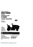
15,5 HP
ELECTRIC START
46" MOWER
HYDROSTATIC
(AUTOMATIC}
LAWN TRACTOR
Model Noo
91 : 2 tzO_rJ
_-Safe_y
,, Assembly
: Opsra_is_t
---Mairstena_ce
Repair
Parts
CAUTION:
Read
and follow
at!
Safety Rules and instructions
before opera[ing this eqLdpment.
Sears, Roebuck
and Co., Hoffman
_-,,, answers
your q___e:,tions
abcbt this product Cali:
1-800°6,_9_59
_7
Sears Craf_sraan He_p Line
5 am - 5 pro, Mort - S_t
Estates,
!L 60179
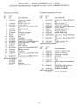
Warranty .................................................
Sdety Rules ...........................................
Product Specifications ...........................
Assembly ................................................
Operation .............................................
Maintenance Schedule .........................
LIMITED TWO YEAR WARRANTY
2
2
5
8
12
19
Maintenance .......................................
19
Service and Adiustments ..................... 23
Storage ................................................
30
Troubleshooting .................................... 31
Repair Parts ......................................... 35
Parts Ordering ....................... Back Cover
ON CRAFSMAN
RiDiNG EQUIPMENT
For two (2) years from the date of purchase, if this Craftsman Riding Equipment is main°
tained, iubricated and tuned up according to the instructions in the owner's manual,
Sears wili repair or repiace, free of charge, any parts found to be defective in materiai or
workmanship.
This Warranty does not cover:
® Expendable items which become worn during normal use, such as blades, spark
plugs, air cleaners, belts, etc.
o Tire replacement or repair caused by punctures from outside objects, such as nails,
thorns, stumps, or glass
Repairs necessary because of operator abuse, negligence, improper storage or accident or the failure to maintain the equipment according to the instructions contained in
the owner's manual.
• Riding equipment used for commercial or rental purposes.
MMITED 90 DAY WARRANTY ON BATTERY
For ninety (90) days from date of purchase, if any battery included with this riding equipment proves defective in material or workmanship and our testing determines the battery will not hold a charge, Sears will replace the battery at no charge. In-home warranty
service on your Craftsman riding equipment is available at no charge for 30 days from
the date of purchase. Please contact your nearest service center° After 30 days from the
date of purchase, warranty service is available by taking your Craftsman riding equipment to your nearest Sears Service Center. (In-home warranty service will still be available after 30 days from the date of purchase but a standard trip charge will apply). This
warranty applies only while this product is in the United States. This Warranty gives you
specific lega! rights, and you may also have other rights which may vary from state to
state.
Sears, Roebuck and Co, D/817 WA, Hoffman Estates, IL 60179
GENERAL
OPERATION
Read, understand, and follow aH instructions in the manual and on the machine
before starting.
o Only allow responsiMe adults, who are
familiar with the instructions, to operate
the machine.
Clear the area of objects such as rocks,
toys, wire, etc., which could be picked
up and thrown by the blade.
o Be sure the area is clear of other people
before mowing. Stop machine if anyone
enters the area.
Never carry passengers.
Do not mow in reverse untess absolutely necessary. Always look down and
behind before and white backing.
Be aware of the mower discharge direco
tion and do not point it at anyone. Do
not operate the mower without either
the entire grass catcher or the guard in
place.
Slow down before turning.
o Never leave a running machine unattended. Always turn off blades, set parking brake, stop engine, and remove
keys before dismounting.
Turnoffbladeswhennotmowing
Stopengine
beforeremoving
g_ass
catcher
or unclogging
chute
Mowonlyindaylight
orgoodartificial
Donotoperate
themachine
whileunder
theinfluence
ofalcohol
ordrugs.
Watch
fortrafficwhenoperating
nearor
crossing
roadways
Useextracarewhenloading
orunload°
irrgthemachine
intoa trailerortruck
::_LOPE
OPERATION
:_lopes
areamajorfactorrelated
toloss./:ficontrol and tipover accidents, which
san result in severe injury or death. All
::topes require extra caution. If you cannot
:;ack up the slope or if you feet uneasy on
t do not mow it.
}0:
Mow up and down slopes, not across.
Remove obstacles such as rocks tree
limbs, etc.
Watch for holes, ruts, or bumps. Uneven
terrain could eve@ms the roach ne Tall
grass can hide obstacles.
Use stow speed. Choose a ow gear so
that you will not have to stop or shift
while on the slope.
Follow the manufacturer's recommen o
dations for wheei wei9hts or counter-weights to irnprove stability
Use ext_a care wth grass catchers or
other _£tachments. These can change
the stabi!ity of @e roach ne
Keep aH movement on the slopes slow
and gradual Do not make sudden
changes in speed or direction.
Avoid start ng or stopping on a slope If
tires lose traction, disengage the biades
and proceed slowIy straight down the
Do nott% _to stabit ze the machine by
putting your foot on the ground.
o Do not use grass catcher on steep
sbpes.
CHLDREH
Tragic accidents can occur if the operator
is not alert to the presence of children.
Children are often attracted to the
machine and the mowing activity. Never
assume that chitdren wilt remain where
you last saw them
o Keep chitdren out of the mowing area
and under the watchf@ care of another
Be alert and turn macMne off if children
enter the area
o Before and when backing, took behind
and down for small children
o Never can'y children They may fal_off
and be seriously injured or interfere with
safe machine operation
o Hever atlow children to operate the
machine
Use extra care when approaching blind
comers shrubs, trees o_*othe obiects
that may obscure vision.
SERVICE
o __seextra care in handling gasoline aad
other fueb. They are fiammabb and
vapors are explosive
Use only an approved container.
Never remove gas cap o__add fuel
with the engine t._nning. AIlow en o
9ie to cool before refue[ing. Do not
smoke.
Never ref(_el the machine indoors.
Never sto_e the sach ne or fise_
containe_ inside where there is an
open flame such as a water heater.
o Never run a maohir-_e insde a dosed
area
i}0 NOT:
Do nottum on slopes unless necessary,
and then, turn stowly and gradually
downhill, if possible.
Do not mow near dropooffs, ditches, or
embankments. The mower could sud_denty turn over if a wheel is over the
edge of a cliff or ditch, or if an edge
caves in.
Do not mow on wet grass. Reduced
traction could cause sliding.
Keep r_uts and bolts especia!ly blade
attachment bets ight and keep equip °
ment in good condition.
o Never tamper with safety devices.
Check their proper operation regularly.
_, Keep machine free of grass, leaves, or
ether debris build-up. Clean oil or fuel
spiHage_ AHow machine to coot before
storing.
Stop and inspect the equipment if you
strike an object° Repair, if necessary,
e
manufacturer's recommended parts,
when necessary.
Mower blades are sharp and can cuL
Wrap the blade(s) or wear gloves, and
use extra caution when servicing them.
Check brake operation frequently.
Adjust and service as required.
before restarting
Never make adjustments or repairs with
the engine running.
Grass catcher components are subject
to wear, damage, and deterioration,
which could expose moving parts or
allow objects to be thrown. Frequently
check components and replace with
Mow up and down slopes (15 ° Max), not
Be sure the area is clear of other people
before mowing. Stop machine if anyone
enters the area
Never carry passengers.
Do not mow in reverse unless absolute o
ly necessary. Always took down and
behind before and while backing.
o Never carry children. They may fati off
and be seriously iniured or interfere with
safe machine operation.
o Keep children out of the mowing area
and under the watchful care of another
responsiMe adult.
Be alert and turn machine off if children
enter the area.
Before and when backing, look behind
and down for small children.
Remove obstacles such as rocks, tree
limbs, etc.
Watch for holes, ruts, or bumps Uneven
terrain could overturn the machine. Taft
grass can hide obstacles.
o Use slow speed. Choose a low gear so
that you will not have to stop or shift
while on the slope.
, Avoid starting or stopping on a slope_ If
tires Io_ traction, disengage the blades
and proceed slowly straight down the
slope.
Do nottum on slopes unless necessary,
and then, turn slowly and gradually
downhill, if possible.
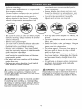
_Look
for this symbol to point out important safety precautions. Jtme_ans CAUTION!!! BECOME AWARE!!! YOUR SAFETY IS INVOLVED.
_WARNING:
The engine exhaust from
this product contains chemicals known to
the State of California to cause cancer,
birth defects, or other reproductive harm.
across
,_CAUTION;
In order to prevent accidental starting when setting up, transporting,
adjusting or making repairs always disconnect spark plug wire and place wire where
it cannot contact spark plug.
4
PRODUCT
SPECmRCATIONS
GASOLINE 3,5GALLONS
CAPACrTY
ANDPCPE: UNLEADED
REGULAR
OIL_[YPE
SAE10W_30
API-SF/SG/SH):
(above
32°F)
SAE5Wo30
(betow
32°F)
OILCAPACITY:
W/FILTER:
4.0PINTS
W/OFILTER:
3.5PINTS
SPARK
PLUG: Champion
RC12YC
GAP:.040")
GROUND SPEED FORWARD: 0 o4.5
(MPH):
REVERSE: 0- 2.0
TIRE PRESSURE: FRONT! 14 PS!
REAR: 10 PSI
CHARGING
SYSTEM:
15 AMPS @ 3600 RPM
BATTERY:
AMP/HR:
30
MIN. CCA: 280
CASE SIZE: U1R
BLADE BOLT
TORQUE:
27-35 FT. LBS.
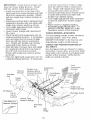
CONGRATULATIONS
on your purchase
of a Craftsman Tractor. It has been
designed, engineered and manufactured
to give you the best possible dependability
and pedormance.
Should you experience any problem you
cannot easily remedy, please contact your
nearest Sears Authorized Service Center.
We have competent, welFtrained techni._
cians and the proper tools to service or
repair this tractor
Please read and retain this manual The
instructions will enable you to assemble
and maintain your tractor properly. Always
observe the "SAFETY RULES'L
MAINTENANCE
AGREEMENT
A Sears Maintenance Agreement is avaiF
able on this product. Contact your nearest
Sears store for details.
CUSTOMER
RESPONSMBIUTtES
Read and observe the safety rules.
o FoHow a regular sched-_e in maintaining, caring for and using your tractor.
o Follow the instructions under "Maintenance" and "Storage" sections of this
owner's manual.
,_WARNING:
This tractor is equipped
with an internal combustion engine and
should not be used on or near any unimproved forest-covered, brush-covered or
grass-covered tand unless the engine's
exhaust system is equipped with a spark
arrester meeting applicable !ocat or state
laws (if any). If a spark attester is used, it
should be maintained in effective working
order by the operator.
In the state of California the above is
required by law (Section 4442 of the
California Public Resources Code). Other
states may have similar laws. Federal
laws apply on federal lands. A spark
arrester for the muffler is available through
your nearest Sears Authorized Service
Center (See REPAIR PARTS section of
this manual).
PARTS BAG CONTENTS
SHOWN
FULL SIZE
(t) Shoulder Bolt
5/16-!8
[
(1) Washer
17/32 x t-3/16 x 12 Gauge
(2) Washers
9/32 x 5/8 x !6 Gauge
(2) Lock Washers
1/4
(2) Washers
3/16 x 3/4 x 16 Gau
(3) Retainer Springs
(Double Loop)
(2)
Loc_k
#10 x 5,/8
(2) Weld Nuts
#10
(4) Retainer Springs
(Sipgle Loop)
_'_ Washers
#10
_
j
6
Pa_te packet separately hs ca4on
Parts Bag conteqts
not showb U! size
(2) Gauge Wheels
-_7_ (2) Latch Hook
Assemblies
Steermg Wheel
Mulcher
Plate
N i
Manual
Parts Bag
Steering
Sleeve
._
(2) Keys
Slope Sheet
Steedng
Sleeve Extension
Your new tractor has been assemMed at the factory with exception of those parts left
unassemb_ed for shipping purposes. _s ensure safe and proper operation of your tractor
aH parts and hardware you assemble must be tightened securely, Use the correct tools
as necessary to insure proper tightness. Review the video cassette before you begin
TOOLS REQUIRE[} FOR
ASSEMBLY
A socket wrench set will make assembly
easier, Standard wrench sizes you need
IMPORTANT: Check for and remove any
staples in skid that may puncture tires
where tractor is to roll off ski&
Steering
Whee! insert
are _isted below.
(!) 3/4'* wrench
(2} 7/16" wrenches
(2) 1/2" wrench
(1) Utility knife
(1)Pliers
(1) 3/'4" Socket w/
drive rachet
(t} Phillips Screwdriver
(1) Tire pressure
gauge
When right or left hand is mentioned in
this manual it means_ from your point of
view, when you are in the operating posio
tion (seated behind the steering wheel).
TO REMOVE
CARTON
TRACTOR
e_,
Lock Nut
-_-
F!at
FROB_
-i
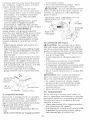
UNPACK CARTON
Remove aHaccessible loose parts and
parts boxes from shipping carton (See
page 6).
• Cut, from top to bottom, along lines on
aHfour corners of shipping carton, and
lay pane_s flat.
Remove mower and package materials.
Check for any additional loose parts or
boxes and remove.
BEFORE
ROLLING TRACTOR
SKiD
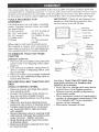
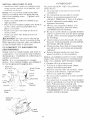
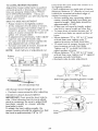
ATTACH STEERING WHEEL"
OFF
Remove Iocknut and large flat washer
from steering shaft.
Position front whee!s of the t'ractor so
they are pointing straight forward.
o SHde the steering sleeve over the steer°
ing shaft.
AHgn tabs and press steering sleeve
extension into bottom of steering wheel
* Position steering wheet so cross bars
are horizontal (left to right) and slide
onto adapter.
Secure steering wheel to steering shaft
with Iocknut and large flat washer previously removed. Tighten securely.
o Snap steering wheel insert into center
of steering wheel.
Remove protective materials from tractor hood and grill.
Steering
Sleeve
Extension
Steering
Shaft
Steering
Sleeve
TO ROLL TRACTOR OFF SKiD (See
Operation section for JocatJon and
function of controls)
• Press lift lever pJunger and raise attachment lift lever to its highest position.
• Reaease parking brake by depressing
clutch/brake pedal.
Place freewheel control in freewheeling
position to disengage transmission (See
"TO TRANSPORT" in the Operation
section of this manual).
• Roll tractor forwards off skid.
HOWTO
SET UP YOURTRACTOR
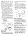
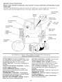
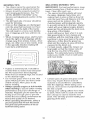
CONNECT BATTERY
_CAUTJON:
Do not short battery termi o
nas by allowing a wrench or any other
object to contact both terminaJs at the
same time. Before connecting batten/,
remove metal bracelets, wristwatch bands,
rings, etc. Positive terminal must be connected first to prevent sparking from accidental grounding.
o Lift hood to raised position.
Open terminal access doors, remove
terminal protective caps and discard.
,f t...... a,,ery is put into service after
month o_"_ ..... indicated on label il_h_l
located between terminals) charge battery for minimum of one hour at 6-10
amps.
First connect RED battery cable to positive (+) battery terminal with hex bolt, flat
washer, lock washer and hex nut as
shown. Tighten securely.
, Connect BLACK grounding came to
negative (-) battery terminal with remainJng hex bolt, flat washer, lock washer
and hex nut. Tighten securely.
o Close terminal access doors Use terminal access doors for:
® Inspection for secure connections (to
tighten hardware).
Inspection for corrosion.
Testing battery.
Jumping (if required).
o Periodic charging.
Discard Terminal
Protective Caps
Hex Nut
Flat
Washer
Lock
Washer
Hex
Bolt
Positive
Cable
Terminal
Access Door ,.:"
ative
Cable
iNSTALL SEAT
Adjust seat before tightening adjustment
knob.
Remove cardboard packing on seat pan.
Place seat on seat pan and assemMe
shoulder boil Tighten shoulder bolt
securely.
Assemble adjustment knob and flat
washer Jooseiy. Do not tighten.
Lower seat into operating position and
sit on seat.
Slide seat unti! a comfortabme position is
reached which allows you to press
dutch!brake pedal aJlthe way down.
• Get off seat without moving its adjusted
position°
Raise seat and tighten adjustment knob
securely.
Seat
Seat Pan
Shoulder
Bolt
Flat Washer
Adjustment Knob
CHECK TiRE PRESSURE
The tires on your tractor were overinflated
at the factory for shipping purposes.
Correct tire pressure is important for best
cutting performance,
Reduce tire pressure to PSI shown in
"PRODUCT SPECIFICATIONS" on page
5 of this manual.
CHECK BRAKE SYSTEM
After you learn how to operate your tractor,
check to see that the brake is properly
adjusted. See "TO ADJUST BRAKE" in the
Service and Adjustments section of this
manual.
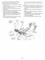
iNSTALL MOWER AND DRIVE BELT
Be sure tractor is on Jevel surface and
mower suspension arms are raised with
attachment lift control. Engage parking
brake.
Cut and remove ties securing anti-sway
bar and belts. Swing antFsway bar to
left side of mower deck.
, Slide mower under tractor with discharge guard to dght side of tractor.
rock and raise front of mower to align
deck pin with the hote in suspension
arm. Retain with double loop retainer
spring with loops down as shown
Connect anti-sway bar to chassis bracket under left footrest and retain with
double loop retainer spdng.
Turn height adjustment knob clockwise
to remove stack from mower suspension.
® Raise mower to highest position,
Assemble gauge wheels (See "TO
ADJUST GAUGE WHEELS" in the
Operation section of this manua 0.
IMPORTANT:
Check beltforproperrout°
inginaH mower pulleygrooves Install
belt into electric clutch pulley groove,
o Install one front iink in top ho!e of the
right hand front mower bracket and right
hand front suspension bracket. Retain
with two single toop retainer springs as
shown,
o tnstall second front link in left hand front
suspension bracket only and retain with
single loop retainer spring as shown,
Turn height adjustment knob counterclockwise untit it stops_
Lower mower linkage with attachment
Hftcontrol
Place the left hand suspension arm on
outward pointing deck pin. If necessary,
rock and raise front of mower to align
deck pin with the hole in suspension
arm. Retain with double loop retainer
spnng with loops down as shown.
SHde left side of mower back and install
the unattached front link in top hole of
the left hand front mower bracket.
Retain with single loop retainer spring
as shown°
P_ace the right hand suspension arm on
outward pointing deck pin. If necessary,
For best cutting results, mower should be
propedy leveledo See "TO LEVEL
MOWER HOUSING _ in the Service and
Adjustments section of this manual
CHECK FOR PROPER POSITION OF
ALL BELTS
See the figures that are shown for replacing motion, mower drive, and mower blade
drive belts in the Service and Adjustments
section of this manual Verify that the
belts are routed correctly,
Front
Chassis
Bracket
Shoulder
Bolt
Double Loop
Retainer Spring
(Outward pointing
deck pins)
Suspension
Arms
Suspension
Brackets
Front Mower
Bracket
Gauge
Single Loop
Retainer Springs
3/8q6
Center
Locknut
Use Pliers For
Discharge Guard
Double Loop
Retainer Spring
Retainer Springs
Anti-Sway
Bar
Idler
Pulley
10
iNSTALL_ULCHERPLATE
installtwolatchhooks
tomulcher
ptate
usingscrewwasher,
lockwasherand
we!dnutasshown_
NOTE:Pr@,assemble
weldnuttoJatch
hookbyinserting
weldnutfromthetop
withhookpointin
9 down.Tighten
hardwaresecurety_
Raiseandholddeflector
shieldinup.rightposition.
Place
frontofmulcher
plateoverfrontof
mower
deckopening
andslideinto
place,asshown
o Hookfrontlatchntoholeonfrontof
mower
deck.
_ Hookrearlatchintohobonbackof
mower
deck.
_CAUTtON:Donotremove
discharge
guardfrommower.
Raiseandhofdguard
whenattaching
mulcher
plateandat!owit
torestonplatewhteinoperation.
TO CONVERT
DISCHARGING
TO BAGGING
OR
Simply remove mubher plate and store in
a safe place, Your mower is now ready for
discharging or installation of optionat grass
catcher accessory.
£_tOTE: It is not necessary to change
blades, The mubher blades are designed
for discharging and bagging also.
Washer
Engine oil is at proper level
Fuel tank is filled with flesh clean,
regular unieaded gasoline.
/ Become familiar with a_[corrtrols --their
bcat on and function. Operate them
before you start the engine.
7 Be sure brake system is in safe operat o
ing condition
,/ It is important to purge the transmission
before operating your tractor fo_ the first
time. Fol}ow proper startir_g and
instructions (See
"TO START ENGINE _'and 'PURGE
TRANSMISSION'
in the Operation
section of this manual).
Hook Points
Nut
Lock
Washer
Washer
Mulcher
Plate
'&.........Screw
DeflectorK_
Shield
"_.
_ All assembly instructions have been
completed.
_/ No remaining loose parts in carton°
e/ Battery s propedy prepared and
charged. (Minimum ! hour at 6 amps)°
_/ Sea_ is adjusted comfortably and
tightened securely.
_/ All tres are propedy inflated. (For
shipping purposes, the tires were
overinfiated at the factoc_')o
_/ Be sure mower deck is propedy bvebd
side4o-sideitror_toto-rear for best cutting
results, (Tires must be propedy inflated
for teveting)o
_/ Check mower and drive betts Be sure
they are routed properly around pulleys
and inside all belt keepers.
_/ Check widng See that aHconnections
are stilJ secure and wires are properly
clamped.
J Before driving tractor, be sure freewheel control is in drive position
t
I
Latch
Hook
,VeJd
qut ""w
_ST
WHILE LEARNING ROW TO USE YOUR
TRACTOR, PAY"EXTRA ATTENTION TO
THE FOLLOWING IMPORTANT ITEMS:
Weld Nut
...........
CHECKL
PLEASE REVIEW THE FOLLOWING
CHECKLIST:
"d\
hh"
11
Thesesymbob
mayappear
onyourtractororinliterature
suppJied
withtheproduct
Learnandunderstand
theirmeaning.
BATTERY
ENGINE
CAUTION
OR
WARNING
ON
ENGINE[
FORWARD
REVERSE
OFF
LIGHTS
OIL PRESSURE
PAST
OVER
ON
SLOW
TEMP
LIGHT
FUEL
CHOKE
MOWER
HEIGHT
UNLOCKED
PARKING
BRAKE
LOCKED
MOWER
LIFT
L
ATTACHMENT
CLUTCH
REVERSE
LOW
HIGH
NEUTRAL
PARKING
BRAKE
ENGAGED
@@@@@
ATTACHMENT
IGNITION
CLUTCH
KEEP
AREA
CLEAR
(SEE
DISENGAGED
SLOPE
SAFETY
RULES
H_RDS
SECTION}
HYDROSTATIC FREE WHEEL
(Hydro Models only)
DANGER, KEEP HANDS AND FEET AWAY
12
KNOWYOURTRACTOR
READTHISOWNER%
MANUAL
ANDSAFETY
RULES
BEFORE
OPERATING
"YOUR
TRACTOR
Compare
theillustrations
withyourtractortofamiliarize
yourself
wkhthetocafions
of
various
controls
andadjustments.
Savethismanual
forfuturereference.
Light Switch
Position
Ignition
Switch
Ammeter
Attachment
Clutch Switch
Throttle/Choke
Control
---.
J
._'_"-...,
Lift Lever
Plunger
Clutch/Brake
Control
Attachment
Lift Lever
Height
Adjustment
Knob
_lBrake
Motion
Control Lever
Freewheel
Control
Our tractors conform to the safety standards of the American
National Standards institute.
ATTACHMENT CLUTCH SWITCH: Used
to engage the mower blades, or other attachments mounted to your tractor.
LIGHT SWITCH: Turns the headlights on
and off.
THROTTLFJCHOKE CONTROL: Used to
control engine speed.
CLUTCH/BRAKE
PEDAL: Used for
declutching and braking the tractor and
starting the engine
FREEWHEEL CONTROL: Disengages
transmission for pushing or slowly towing
the tractor with the engine off.
HEIGHT ADJUSTMENT KNOB: Used to
adjust the mower cutting height.
MOTION CONTROL LEVER: Selects the
speed and direction of the tractor,
A_ACHMENT
LiFT LEVER: Used to
raise and lower the mower deck or other
attachments mounted to your tractor.
LiFT LEVER PLUNGER: Used to release
attachment lift lever when changing its
position.
iGNiTiON SWITCH: Used for starting and
stopping the engine.
AMMETER: indicates battery charging (+)
or discharging (o),
PARKING BRAKE: Locks clutch/brake
into the brake position.
13
HOWTOUSEYOURTRACTOR
Yourtractor
isequipped
withanoperator
presence
sensing
switch.
Whenengine
is
running,
anyattempt
bytheoperator
to
leavetheseatwithout
firstsetting
the
parking
brakewiltshutofftheengine.
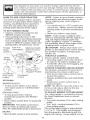
TO SET PARKING BRAKE
"BRAKF position and hotd,
, Place parking brake lever in "ENGAGED" position and release pressure
from dutch/brake pedal Pedai shoutd
remain in "BRAKE" position Make sure
parking brake will hold tractor secure.
Throttle/
Choke
Push-in to
Attachment Clutch
Switch Pull Out To
"Engage"
-_.."Engaged"
Peda! "Drive"
Position
Position
"Disengag ed_
Position
STOPPING
MOWER BLADES To stop mower blades, move attachment clutch switch to "DISENGAGED"
position.
GROUND DRIVE °
Tb stop ground drive, depress
cmutch/brake pedal into full "BRAKE"
position.
Move motion control lever to neutral (N)
position.
_MPORTANT: The motion control lever
does not return to neutrat (N) position
when the clutch/brake pedal is depressed.
ENGINE '_ Move throttle contro_ to slow position.
14
NOTE: Failure to move throttle control to
stow position and allowing engine to idle
before stopping may cause engine to
"backfireL
Turn ignition key to _'OFF" position and
remove key. AJways remove key when
leaving tractor to prevent unauthorized
use.
Never use choke to stop engine.
NOTE: Under certain conditions when
tractor is standing idle with the engine running, hot engine exhaust gases may
cause "browning" of grass. To eliminate
this possibility, always stop engine when
stopping tractor on grass areas.
,_ CAUTION: Always stop tractor corn o
p_etdy; as described above, before leaving
the operatoCs position; to empty grass
catcher, etc.
THROTTLE CONTROL
Atways operate engine at full throttle,
o Operating engine at less than full throt o
tie reduces the battery charging rate.
Full throttle offers the best bagging and
mower performance.
TO MOVE FORWARD AND BACKWARD
The direction and speed of movement is
controlled by the motion control lever.
o Start tractor with motion control lever in
neutral (N) position.
o Re}ease parking brake and c_utch/brake
pedal
Slowly move motion control Jever to
desired position.
NOTE: The effort to move the motion controt Eever will reduce after the first few
hours of use. This is normal
TO ADJUST MOWER CUTTING HEIGHT
The cutting height is controlled by turning
the height adjustment knob in desired
direction,
o Turn knob clockwise (G) to raise cutting
height.
Turn knob counterclockwise
(O)to
lower cutting height.
The cutting height range is approximately
1-!/2" to 4". The heights are measured
from the ground to the Hade tip with the
engine not running. These heights are ap-
ment chtch contro_
: roximate
andmayvarydepending
upon
TO STOP MOWER BLADES odisen o
oii conditions
heightofgrassandtypes
f grassbeingmowed.
age attachment c_utch control
CAUTION: Do not operate the mower
Theaverage
lawnshould
becutto
_Fp,,_-x
man.Iv
2-.2 mc_es
during
the witho _t ether the entire grass catcher, on
coo[season
andtoover3 inches
dunng mowers so equipped_ or the discharge
hotmonths.Forhealthier
andbetter
guard in placeo
looking
lawns,mowoftenandafter
Lift Lever
Attachment Clutch Attachment
moderato
growth.
Switch Pull Out To High Position
Forbestcutting
performance,
grass
"Engage*'
over6 inchesinheightshouldbe
\
.}/Position
mowed
twice.Makethefirstcutre[a
_
/
Low
tivelyhigh;thesecond
todesired
height.
Discharge
['OADJUST
GAUGE
WHEELS
Guard
:_auge
wheelsarepropedy
adjusted
Push _n To
_,w_e_
_h_y
areo,_, ,,,x '_,, the ground ,_,h_,,,,_,, "Disengage'
nower [s at the desired cutting height in
:}perating position. Gauge wheels then
<eep the deck in proper position to help
:)revent scalping in most terrain condi ,_
:ons.
Adjust gauge wheels with tractor on a
flat _eve[ sudace.
Adjust mower to desired cuttin 9 height
(See "TO ADJUST MOWER CUTT!NG
HEIGHT _in the Operation section of
this manual).
With mower in desired height of cut position, gauge wheels should be assemo
bled so they are s_ightly off the ground°
Install gauge wheel in appropriate hole
with shoulder bolt, 3/8 washer, and 3/818 Iocknut and tighten securety_
Repeat for opposite side installing
gauge wheel in same adiustment hole.
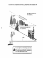
TO OPERATE
ON HILLS
_CAUT_ON:
Do notdriveup ordown
hills
withslopesgreaterthan 15° and do
notdriveacross any slope..
Use theslope
guide providedatthe back ofthismanual
Choose theslowestspeed beforestadingup or down Mils
o Avoid stoppingor changing speed on
hills.
o Ifslowingisnecessary,move throttle
controllevertoslower positiom
Ifstoppingisabsolutely
necessary,push
ck_tchibrake
pedal quicklytobrake posio
tionand engage parkingbrake.
Move motioncontrol[everto neutral
(N)
position°
_MPORTAN'T: The moton controJ [eve_
does not return to neutral (N) posit on
when the dutch/brake peda_ is depressed°
o To restart movement, slowly re_ease
parking brake and dutch/brake pedal.
Stowly move motion control lever to
slowest setting.
o Make al! turns slow_yo
TO TRANSPORT
When pushing or towing your tracto< be
sure to disengage transmission by ptacing
freewheel control in freewheel ng position.
Freewheel control is tocated at the rear
drawbar of tractor.
o Raise attachment Hft to highest position
with attachment lift control.
o PuH freewheel control knob out and hold
in position by inserting retainer spring
into forward hole of control rod
i_OOPERATE MOWER
four tractor is equipped with an opelator
}resence sensing switch. Any attempt by
he operator to _eave the seat with the
imgine running and the attachment clutch
mgaged w[H shut off the engine.
Select desired height of cut.
Lower mower with attachment lift corn
troL
Start mower blades by engaging attach15
o Donotpushortowtractor
atmorethan
quantities that can be used within 30
days to assure fuel freshness
Tbreengage
transmission,
reverse
mMPORTANT: When operating in tempera°
aboveprocedure.
tures below 32°F(0°C), use fresh, dean
NOTE:
T0protect
hoodfromdamage
when winter grade gasoline to hetp insure good
transporting
yourtractor
onatruckora
cotd weather starting
trailer,
besurehoodisclosed
andsecured _WARNtNG: Experience indicates that
totractor.
Useanappropriate
means
of
alcohol blended fuels (called gasoho[ or
tyinghoodtotractor
(rope,
cord,etco).
using ethanol or methanol) can attract
moisture which leads to separation and
formation of acids during storage Acidic
gas can damage the fuel system of an
engine while in storage TO avoid engine
proMems, the fue_ system should be emp...
tied before storage of 30 days or _onger.
n_;_, _h.....
_"_" start _'^ engine and ,_^"
it run until the fuemlines and carburetor are
empty° Use fresh fuel next season. See
Storage Instructions for additionaJ informaTOWINGCARTS AND OTHER
tiono Never use engine or carburetor
ATTACHMENTS
cleaner products in the fuel tank or permaTow onty the attachments that are recomn,ent damage may occur.
mended by and comply with specifications
ACAUT!ON:
Fill to bottom of gas tank
of the manufacturer of your tractor. Use
filler neck. Do not overfill. Wipe off any
common sense when towing° Too heavy of
spilled oil or fuel Do not store, spill or use
a foad, whiJe on a slope, is dangerous
gasoline near an open flame.
Tires can lose traction with the ground and
TO START ENGINE
cause you to lose control of your tractor.
When starting the engine for the first time
BEFORE STARTING
THE ENGmNE
or if the engine has run out of fue!, it will
CHECK ENGINE OIL LEVEL
take extra cranking time to move fuel from
the tank to the engine.
, The engine in your tractor has been
Be sure freewheel control is in the
shipped, from the factory, already filled
with summer weight oil.
transmission engaged position.
Sit on seat in operating position,
Check engine oi! with tractor on level
depress clutch/brake pedal and set
ground.
parking brake.
Unthread and remove oil fill cap/dip, Place motion control lever in neutral (N)
stick; wipe oil off. Reinsert the dipstick
position.
into the tube and rest oit fir1cap on the
Move attachment dutch to "DlSEN o
tube. Do not thread the cap onto the
tube° Remove and read oJJlevel. If necGAGED ° position.
® Move throttle controt to choke position.
essary, add oil until "FULL" mark on
NOTE: Before starting, read the warm and
dipstick is reached. Do not overfi{L
cold starting procedures below.
o For cold weather operation you should
Insert key into ignition and turn key
change oil for easier starting (See "OIL
VISCOS_TY CHART" in the Customer
clockwise to "STAR_ position and
retease key as soon as engine starts.
Responsibilities section of this manual).
Do not run starter continuously for more
To change engine oiJ, see the Customer
than fifteen seconds per minute° ff the
Responsib_Jities section in this manual
engine does not start after several
ADD GASOLINE
attempts, move throttJe controt to fast
, FHJfuel tank. Use fresh, c_ean, regular
position, wait a few min_es and try
unleaded gasoline with a minimum of 87
again° If engine stiti does not start,
octane (Use of _eaded gasoline will
move the throttle control back to the
increase carbon and _ead oxide
choke position and retry.
deposits and reduce valve Jife). Do not
WARM WEATHER STARTING (50 ° F and
mix oil with gasoline. Purchase fuel in
above)
16
Whenengine
starts,movethethrottle
controt
tothefastposition.
• Theattachments
andground
drivecan
r;owbeused.!ftheengine
doesnot
accept
theload,restart
theengine
and
allowittowarmupforoneminute
using
thechokeasdescribed
above.
COLDWEATHER
STARTING
(50° Fand
below)
o Whenengine
starts,altowengine
torun
withthethrottle
control
inthechoke
position
untiltheengine
runsrougM}i
thenmovethrottle
control
tofastposition.Thismayrequire
anengine
warm-upperiodfromseverat
seconds
tosev°
..,,u_o,uepen._,,,_
_,,,,,,etemperature.
HYDROSTATIC
TRANSMISSION
WARM
UP
• Before driving the unit in cold weather,
the transmission should be warmed up
as follows:
Be sure the tractor is on mevelground.
Place the motion control lever in neutral.
Release the parking brake and let the
clutch!brake slowly return to operating
position.
® Allow one minute for transmission to
warm up. This can be done during the
engine warm up period.
• The attachments can also be used during the engine warm-up period after the
transmission has been warmed up.
NOTE: At a high altitude (above 3000
feet) or in cold temperatures (below 32 F)
the carburetor fuel mixture may need to be
adjusted for best engine performance.
See "TO ADJUST CARBURETOR" in the
Service and Adjustments section of this
manual.
PURGE TRANSMISSION
_,CAUTION:
Never engage or disem
gage freewheel lever while the engine is
running.
To ensure proper operation and performance, it is recommended that the transo
mission be purged before operating tractor
for the first time. This procedure will
remove any trapped air inside the transmission which may have developed during
shipping of your tractor.
17
!MPORTANT: Should your transmission
require remova_ for service or replace o
merit, it shoutd be purged after reinstaHao
tion before operating the tractor.
Place tractor safely on level surface with
engine off and parking brake set.
Disengage transmission by placing freewheel control in freewheeling position
(See "TO TRANSPORT" in this section
of manual).
Sitting in the tractor seat, start engine.
After the engine is running, move throttle control to slow position. With motion
control lever in neutral (N) position,
slowly disengage clutch/brake pedal.
o Move motion control lever to full forward
position and ho_d for five (5) seconds.
Move lever to full reverse position and
hold for five (5) seconds. Repeat this
procedure three (3) times.
NOTE: During this procedure there will be
no movement of drive wheels. The air is
being removed from hydraulic drive system.
Move motion control lever to neutral (N)
position. Shut off engine and set parking
brake.
Engage transmission by placing freewhee_ control in driving position (See
"TO TRANSPORT" in this section of
manual).
Sitting in the tractor seat, start engine.
After the engine is running, move throttle control to half (1/2) speed. With
motion control lever in neutral (N) posi o
tion, slowly disengage clutch!brake
pedal.
Slowly move motion control lever for_
ward; after the tractor moves approxi mately five (5) feet, slowly move motion
control lever to reverse position. After
the tractor moves approximately five (5)
feet return the motion control lever to
the neutral (N) position. Repeat this procedure with the motion control lever
three (3) times.
Your tractor is now purged and ready for
normal operation°
MOWENG
TIPS
o
o
,
o
lYlULCHING
Tire chains cannot be used when the
mower housing is attached to tractor:
Mower shouid be propedy teveled for
best mowing performance° See TO
LEVEL MOWER HOUSING '_in the
Service and Adjustments section of this
manual
The left hand side of mower should be
used for trimming.
Drive so that clippings are discharged
onto the area that has been cut. Have
the cut area to the right of the tractor.
This will result in a more even distribuo
'".... v_ clippi ngs and more "_
du_
..............
.......
ring.
When mowing large areas, start by turning to the right so that clippings will discharge away from shrubs, fences, driveways, etc° After one or two rounds, mow
in the opposite direction making left
hand turns until finished.
lYlOWING
TIPS
IMPORTANT: For best performance, keep
mower housing free of built-up grass and
trash Clean after each use.
The special mulching blade will recut
the grass clippings many times and
reduce them in size so that as they fall
onto the lawn they will disperse into the
grass and not be noticed. Also, the
mulched grass will biodegrade quickly
to provide nutrients for the lawn. Always
mulch with your highest engine (blade)
speed as this will provide the best recutring action of the blades.
Avoid cutting your '........ "^" it is .....
Wet grass tends to form clumps and
interferes with the mulching action. The
best time to mow your lawn is the early
afternoon. At this time the grass has
dried and the newly cut area will not be
exposed to the direct sun.
For best results, adjust the mower cut:
ring height so that the mower cuts off
only the top one-third of the grass
blades. For extremely heavy mulching,
reduce your width of cut on each pass
and mow slowly+
Max 1/3
o If grass is extremely tall, it should be
mowed twice to reduce load and possible fire hazard from dried clippings
Make first cut relatively high; the second
to the desired height.
Do not mow grass when it is wet. Wet
grass will plug mower and leave unde o
sirable clumps. Allow grass to dry
before mowing.
, Always operate engine at ful! throttle
when mowing to assure better mowing
performance and proper discharge of
material. Regulate ground speed by seo
lecting a low enough gear to give the
mower the best cutting performance as
well as the quality of cut desired.
, When operating attachments, select a
ground speed that will suit the terrain
and give best performance of the attachment being used.
o Certain types of grass and grass conditions may require that an area be
mulched a second time to completely
hide the clippings When doing a second cut, mow across or perpendicular to
the first cut path.
o Change your cutting pattern from week
to week. Mow north to south one week
then change to east to west the next
week. This will help prevent matting and
graining of the lawn.
18
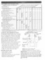
::USTOMER RESPONSBIUTSES
i - change
2 Serv_c_
3 - if
equ
4 - R_fac÷
o e _>f_en wh@l cper ti_ g b_dsr a heaey ioad or in high
more often wh_; _t_e_at_g _l dir[y or dusty conditions.
pped
with
blades
:_ENERAL
oJ
fi_ter
p,or÷
change
often
whe_
o_
#_ve'-y
50
anYoient
temperatures.
5
6
If r_quf_s_td
Not req_d
wit!_ _dj lsta_le system
_f ÷quipf_d
w_th _a_te_r_e
free
balle_y
ho_rs
r_:o_v_ng _n san_
so_
RECO_,_ENDATIONS
he warranty on this tractor does not cover
:eros that have been subjected to operator
_.buseor negligence TO receiw_ furl value
_om the warranty, operator must maintain
factor as instructed in this manual Some
diustments will need to be made periodi o
:afiy to propedy maintain your tractor
ql adjustments in the Service and
(djustments section of this manuat should
e checked at bast once each season.
Once a year you should replace the
spark ptu% cban or replace air fi_ter, and
check blades and belts for wear A new
spark p_ug and dean air fIter assure
proper air fuet mixture and help your
engine run better and last !onger.
@ Front Whee!
BearingZerk
Front
Wheel
Bearing
Zerk
@ Engine
@ Attachmemt
Clutch
i
Pivot(s)
i.........
@ SAE 30 or 10w30 Motor OIL
@ Genera_ Purpose Grease
@ Refer to Maintenance 'Engir_e" Section
_EFORE EACH USE
_MPORTANT:
Do not oil or grease the pivot
Check engine oil!eveI_
points which have special nylon bear-ings.
Check brake operation,
Viscous lubricants will attract dust and diR
Check tirepressure
Check operatorpresence and interlockthat wil_ shorten the life of the se_f k_bdcating
bearings. If you feel they must be lubricated,
systems farproperoperation,
use only a dry, powdered graphite type lubrio
Check forloosefasteners
cant sparingly.
19
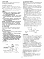
TO SHARPEN BLADE
TRACTOR
NOTE: We do not recommend sharpening
Always
observe
safetyruleswhenper°
blade, but if you do, be sure the blade is
forming
anymaintenance,
balanced°
BRAKE
OPERATION
Care should be taken to keep the Made
Iftractorrequires
morethansix(6)feet
baJanced. An unbalanced blade wilt cause
stopping
distance
athighspeedinhighest excessive vibration and eventual damage
gear,thenbrakemustbeadjusted°
(See to mower and engine.
"TOADJUST
BRAKE"
intheService
and
The b_ade can be sharpened with a file
Adjustments
section
ofthismanual).
or on a grinding wheel. Do not attempt
to sharpen while it is on the mower.
TIRES
To check blade balance, you will need a
Maintain
proper
airpressure
inaJltires
5/8" diameter steel bolt, pin, or a cone
(See"PRODUCT
SPECIFICATIONS
'_
balancer. (When using a cone balancer,
on page 5 of this manual)°
Keep tires free of gasoline, oil, or insect
control chemicals which can harm rubber.
o Avoid stumps, stones, deep ruts, sharp
objects and other hazards that may
cause tire damage.
NOTE: To sea! tire punctures and prevent
fiat tires due to slow leaks, tire sealant
may be purchased from your Ioca_parts
dealer° Tire sealant also prevents tire dry
rot and corrosion.
follow the instructions
NOTE: Do not use a nail for balancing
blade. The lobes of the center hole may
appear to be centered, but are not.
, Slide blade onto an unthreaded portion
of the steel bolt or pin and hold the bolt
or pin parallel with the ground, if blade
is balanced, it should remain in a horizontal position, if either end of the blade
moves downward, sharpen the heavy
end until the blade is balanced.
BLADE CARE
For best results mower blades must be
kept sharp. Replace bent or damaged
blades.
BLADE REMOVAL
Raise mower to highest position to allow
access to blades.
Remove hex bolt, lock washer and flat
washer securing blade.
Install new or resharpened blade with
trailing edge up towards deck as shown.
Reassemble hex bolt, lock washer and
fiat washer in exact order as shown
® Tighten bolt securely (27-35 Ft. Lbs.
torque).
iMPORTANT:
treated.
Center Hole
5!8" Bo!
or Pm
Lock Was
Hex Bolt (Grad:-8}*_'"_
"_-4_
BATTERY
Your tractor has a battery charging system
which is sufficient for normal use. However, periodic charging of the battery with an
automotive charger will extend its life.
® Keep battery and terminals clean.
Keep battery bolts tight.
Keep small vent holes open.
- Recharge at 6-10 amperes for t hour.
NOTE: The original equipment battery on
your tractor is maintenance free. Do not
attempt to open or remove caps or covers.
Adding or checking teve! of eJectroJyte is
not necessary.
TQ CLEAN BATTERY AND TERMINALS
Corrosion and dirt on the battery and ter=
minais can cause the battery to "leak"
power.
Remove termina! guard,
- Disconnect BLACK battery cable first
then RED battery cable and remove
battery from tractor.
Blade bolt is Grade 8 heat
Blad\kx4_j_\_
.
/
BJade
Assembly
Flat
supplied with bal-
Mandrel
TraiJing
Edge
Up
"%_
*A Grade 8 heat treated bolt can be
identified by six lines on the bolt head.
2O
Rinsethebattery
withplainwaterand Check the crankcase oH _evel before start
ing the engine and after each eight (8)
dry.
Cleanterminals
andbatter,/cable
ends hours of operation. Tighten oil fill cap/dipwithwirebrushunti!bdghto
stick securely each time you check the oi_
Coatterminals
withgrease
orpetroleumlevel
jelly.
TO CHANGE ENGINE OiL
Reinstall
battery
(See"CONNECT
BAT- Determine temperature range expected
TERY"
intheAssembly
section
ofthis
before oil change_ All oil must meet API
manual).
service classification SF, SG, or SH.
VoBELTS
Be sure tractor is on level surface.
Check
V-betts
fordeterioration
andwear
Oi! will drain more freely when warm.
after100hoursofoperation
andreplace
if , Catch oil in a suitable container.
necessary°
Thebeltsarenotadjustable. * Remove oil fill cap/dJpsticko Be carefu!
not to aiiow dirt to enter the engine
Replace
beltsiftheybegintoslipfrom
when changing oil
wear.
Remove drain plug.
TRANSAXLE
COOLING
* After oil has drained completely, replace
The transmission fan and cooling fins
should be kept clean to assure proper
cooling.
Do not attempt to clean fan or transmission while engine is running or while the
transmission is hot.
o inspect coo_ing fan to be sure fan
blades are intact and clean.
* Inspect cooling fins for dirt, grass clippings and other materials. To prevent
damage to seals, do not use compressed air or high pressure sp._ayer to
clean cooling fins.
TRANSA×LE PUMP FLUID
The transaxle was sealed at the factory
and fluid maintenance is not required for
the life of the transaxle. Should the
transaxle ever leak or require serdcing,
contact your nearest authorized service
center.
o11drain plug and tighten securely.
* Refill engine with oil through oi_fill dipstick tube. Pour slowly. Do not overfi&
For approximate capacity see "PRODUCT SPECIFICATIONS" on page 5 of
this manual
o Use gauge on oil fill cap/dipstick for
checking level Insert dipstick into the
tube and rest the oil lilt cap on the tube.
Do not thread the cap onto the tube
when taking reading.
Keep oil at
"FULL" line on dipstick. Tighten cap
onto the tube securely when finished.
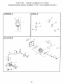
Air Cleaner
Knob
Cover
Nut
Foam
Pre-Cleanel
Grommet
Air Cleaner
Base
ENGINE
LUBRICATION
creen
Only use high quality detergent oil rated
with API service classification SF, SG, or
SH. Select the oil's SAE viscosity grade
according to your expected operating temperature.
Oil Fill
,stick
Air
Paper
Cartridge
.Oil Drain Plug
°c -_0o
op.
-2c_,
-20o
-10o
eo
30.
d"
10 °
32- 4o _
60
20 °
._
_,,
40 °
ice _
CLEAN
AIR SCREEN
Air screen must be kept free of dirt and
chaff to prevent engine damage from overheating° Clean with a wire brush or compressed air to remove dirt and stubborn
dried gum fibers.
Change the oil after every 50 hours of
operation or at least once a year if the
tractor is not used for 50 hours in one
year.
21
CLEAN
AIRINTAKL_COOLING
AREAS
adapter:
Toinsureproper
cooting,
makesurethe
Apply a thin coating of new engine oil to
grassscreen_
cooting
fins,andother'
the rubber gasket on replacement oil ill°
ter.
externam
surfaces
oftheengine
arekept
c_ean
ataHtimes
install replacement oi_fitter on fifter
Every100hours
ofoperation
(more
often
adapter. Turn oiJ fiJter clockwise untiJ
underextremely
dusty_
dirtyconditions), rubber gasket contacts the fitter adapter,
remove
theblower
housing
andother
then tighten filter an additJona! 1/2 turn.
cooling
shrouds.
Cleanthecooling
fins
andexternat
surfaces
asnecessary.
Make
surethecooling
shrouds
arereinstalled°
NOTE:Operating
theengine
witha
blocked
grassscreen,
dirtyorplugged
cooling
fins,and/or
cooting
shrouds
re
moved
wiltcause
engine
damage
dueto
overheating
AIRHLTER
O
"fourengine
wiltnotrunpropedy
usinga
dirtyairfilter.Cleanthefoampre-cleaner Fill crankcase with new oil (See "TO
aftereve@'
25hoursofoperation
orevery
CHANGE ENGINE OIU _in this section
season.Service
papercartridge
every
of this manual}. For approximate capac100hoursofoperation
oreveryseason,
ity see "PRODUCT SPECIFICATIONS"
whichever
occurs
first
page 5 of this manual
Ser_4ce
aircleaner
moreoftenunderdusty o on
Start the engine and check for oiJ leaks.
conditions.
Correct any leaks before ptacing engine
Remove
knobandcover.
into full operation°
Remove
wingnutandaircleaner'
from MUFFLER
base.
Inspect and replace corroded muffter and
TOSERVICE
PRECLEANER
spark arrester (if equipped) as it coutd creo SWefoampre_cteaner
offcartridge
ate a fire hazard and/or damage.
Washitinliquiddetergent
andwater° SPARK PLUGS
Squeeze
itdryina cleancloth.Allowit Replace spark plugs at the beginning of
todry.
each mowing season or after every 100
o Saturate
itinengine oil Wrap it in
hours of operation whichever occurs first.
clean, absorbent cloth and squeeze to
remove excess oil
Spark plug type and gap setting are
shown in "PRODUCT SPECIFICATIONS"
on page 5 of this manuat.
_N°LJNE FUEL FILTER
The fueJ fiJte_ shoukJ be reptaced once
each season. _ffuel filter becomes
clogged, obstructing fuel flow to carbure-.
tor, replacement is required.
o With engine cool, remove filter and plug
fuel line sections.
Place new fueJ filter in position in fuel
line with arrow pointing towards carbu°
retch
, Be sure there are no fuel Jine leaks and
clam.ps are properly positioned.
TO SERVICE CARTRIDGE
o Replace a dirty, benL or damaged car°
HOTE: Do not wash the paper ca,,lridge
or use pressurized air, as this witt damage
• Reinstall the pre_cleaner (cleaned and
oiled) over the paper cartridge
o Reassemble air cteaner, wing nut, cover
and tighten knob securely.
ENGINE O_L FILTER
Replace the engine oit filter every season
or every other oil change if the tractor is
used more than t00 hours in one year.
o Drain oil from engine crankcase (See
"TO CHANGE ENGINE OIL" in this sec o
tion of this manual, through step remove
drain plug)°
o Remove oil fiJter and wipe off filter
22
CLEANING
_ Cleanengine,
battery:
seat,finish_
etc
ofal!foreignmatter
Keepfinished
surfaces
andwheels
free
ofallgasoline,
oil,etc
o Protect
painted
surfaces
withautomootivetypewax°
Wedonotrecommend
usingagarder_
hosetocleanyourtractoruntess
theetec_
trica_
system,
muffler,
airfi_ter
andcarbureo
totarecovered
tokeepwaterout°Water
inengine
canresuitina shortened
engine
life_
_CAUTmON:
Before
performing
anyservice
ora@ustments:
o Depress
clutch/brake
pedalfullyandsetparking
brake
o Ptacemotion
control
leverinneutral
(N)position.
Place
attachment
clutchin"DISENGAGED
'_position.
o Turn ignition key "OFF " and remove key.
o Make sure the Mades and aH moving parts have completely stopped_
o Disconnect spark plug wire from spark plu 9 and place wire where it cannot come
in contact with plug.
_RACTOR
o Remove two retainer springs from each
front link and remove links.
Slide mower forward and remove beat
from electnc dutch pulley,,
o Stide mower out from under right side of
tractor.
IMPORTANT: If an attachment other than
the mower deck is to be mounted on the
tractor_ remove the front tinkso
_O REMOVE MOWER
Place attachment clutch in "DISENo
GAGED" position,
Turn height adjustment knob to lowest
setting.
Lower mower to its lowest position.
Remove retainer spring holding antiswaybar to chassis bracket and diseno
gage anti-swaybar from bracket.
Remove retainer springs from suspension arms at deck and disengage arms
from deck.
Raise attachment lift to its highest position.
TO INSTALL _,_OWER
Fol!ow procedure described in "iNSTALL.
MOWER AND DRIVE BELT '_in the
Assembly section of this manual.
Adjustment
Nuts
Suspension
Arms
Links
Front Mower
Bracket
Front
)ension
B_acket
/
Front
Suspension
Bracket
Springs
Front Mower
Bracket
Retainer
Spring
Anti-Sway
Bar
Retainer
Springs
23
lower than the _ear when the mower is in
its highest position
Check adjustment on right side of tractor.
Measure distance 'D" directly in front and
behind the mandrel at bottom edge of
mower housing as shown.
, Before making any necessary adjustments, check that both front links are
equat in length. Both links should be
approximately 10-3/8".
o tf tinks are not equa_ in length, adjust
one link to same length as other link.
o To lower front of mower loosen nut "E"
on both front !inks an equal number of
turns
When distance "D*' is 1/8" to 1/2" lower
at front than rear, tighten nuts "F"
against trunnion on both front links.
To raise front of mower, loosen nut "F
from trunnion on both front links.
Tighten nut "E" on both front links an
equa_ number of turns.
, When distance "D" is 1/8" to 1/2" lower
at front than rear, tighten nut "F" against
trunnion on both front links.
Recheck side-to-side adjustment.
TO LEVEL MOWER HOUSING
Adiust the mower whi{e tractor is parked
on level ground or driveway. Make sure
tires are propedy inflated (See _PROD o
UCT SPECIFICAT_ONS_)o If tires are
over or undednflated, you will not properly
adjust your mower.
SIDE_TQ_S_DE ADJUSTMENT
• Raise mower to its highest position
At the midpoint of both sides of mower,
measure height from bottom edge of
mower to ground. Distance "An on both
sides of mower should be the same or
within 1/4" of each other.
If adjustment is necessary, make adjustment on one side of mower only.
To raise one side of mower, tighten lift
link adjustment nut on that side.
o To mowerone side of mower, loosen lift
Iink adjustment nut on that side.
NOTE:
Each ful_turn of adjustment nut
Bottom
Mandre_
'_
Suspension
Arm
Both Front Links Should be Equa_ in Length
Lift Link Adjustm_t
Nut
/
will change mower height about 1/8"o
Recheck measurements after adjusting.
/
/
FRONToTO_BACK ADJUSTMENT
mMPORTANT: Deck must be level side-to _
side. ff the following front,otooback adiustmerit is necessary, be sure to adjust both
front links equally so mower wilt stay
level side4o-side.
To obtain the best cutting results, the
mower housing shouad be adjusted so that
the front is approximately 1/8" to 1/2"
Trunnion
Front
Links
24
Nut "G"
TOREPLACE
MOWER
DR_VE
BELT
MOWER
DRWE
BELTREMOVAL
Parktractoronalevelsurface°
Engage
parking
brake
Remove
screws
fromlefthandmandrel
coverandremove
cover,
e Rollbeltoverthetopoflefthandmandretpulley.
Remove
beltfromelectric
clutchpulley.
o Remove
beltfromidlerpulleys.
Remove
anydirtorgrassclippings
whichmayhaveaccumulated
around
mandrels
andentireupperdecksurface_
Check
primao,
idterarmandtwoidlers
toseethattheyrotatefreely.
Screws
Left Hand
Mandrel
Cover
o Besurespringis securely
hooked
toprF
maryidlerarmandboltinmower
hous_
ing.
MOWER
DRIVEBELTINSTALLATION
Installbe_t
inbothidlers.Makesurebelt
isinbothbeltkeepers
attheidlersas
shown
Installnewbeltontoelectric
clutchpulo
tey,
®Roltbeltintouppergroove
oflefthand
mandrel
pulley.
o Carefully
checkbeltrouting
making
sure
beltisinthegrooves
correctly
and
insidebettkeepers
Reassemb!e
!efthandmandrel
cover.
Idler
Pulleys
Electric
Clutch
X
Mower
Drive Belt
Mandrel
Primary
Idler Arm
Belt
Keepers
25
TOREPLACE
MOWER
BLADEDR[IVE
BELT
Pa_thetractor
onlevelsurfaceEngage
parking
brake.
o Remove
mowerdrivebeff(See"TO
REPLACE
MOWER
DRIVE
BELT'in
thissection
ofthismanua0o
Remove
mower(See"TOREMOVE
MOWER"
inthissection
ofthismanual).
* Remove
fourscrews
fromdghthand
mandrel
coverandremove
cover.
Unhook
spdngfromboltonmower
housing.
Carefully
rol[be_t
offdghthandmandre[
* Remove belt from center mandrel puF
{ey, idler pulley, and left hand mandrel
pulley.
- Remove any dirt or grass which may
have accumulated around mandrels and
Left Hand
Mandrel
Mower Blade
Drive Belt
entire upper deck surface.
Check secondary idler arm and idler to
see that they rotate free_y.
Be sure spdng is hooked in secondary.
idier arm and sway-bar bracket.
}nsta[[ new bett in lower groove of left
hand mandre8 pulley; idler puHe_,;and
center mandrel pulley as shown.
Rol_ bert over right hand mandreJ pulley.
Make sure beff is in all grooves properly.
Reconnect spring to boJt in mower
housing and reinstall right hand mandreJ
cover,
ReinstaJt mower to tractor (See
"INSTALL MOWER AND DRIVE BELT"
in the AssemMy section of this manual).
Reassemble mower drive belt (See '%0
REPLACE MOWER DRIVE BELT" in
this section of this manua0.
Center
Mandrel
Idler
Right Hand
Mandrel
Cover
Idler Arm
S
Bracket
I v A_.,JUST BRAKE
further maintenance is necessary.
Contact your nearest authorized service center/department.
With Parking Brake "Engaged"
Your tractor is equipped with an adjustable
brake system which is mounted on the
side of the transaxle.
ff tractor requires more than six (6) feet
stopping distance at high speed in highest gear, then brake must be adjusted.
® Depress c_utch/brake pedal and engage
parking brake.
, Measure distance between brake operating arm and nut "A" on brake rod.
[f distance is other than 1-9/16s", loosen
jam nut and turn nut "A" until distance
becomes 1-9/16". Retighten jam nut
against nut "A".
o Road test tractor for proper stopping
distance as stated above. Readjust if
necessary. If stopping distance is still
greater than six (6) feet in highest gear,
Jam Nut
Operating
Arm
Do Not touch this nut. If further brake adjustment is necessary contact your nearest authorized service center/department
26
!O REPLACE
MOTION
DR_VE
BELT
::,ark
thetractoronIeve_
sudaceEngage
}arkingbrake For assistance there is a
se!t installation guide decal on bottom side
sf left feotresL
Remove mower (See "TO REMOVE
MOWER" in this section of this manual.)
Disconnect dutch wire harness_
Remove clutch Iocatoro
Remove upper belt keeper_
Remove belt from stationary idler and
clutching idtero
Pull belt slack toward rear of tractor.
Carefully remove bett upwards from
transmission input pulley and over cooF
ing fan Mades_
Pul_ belt toward front of tractor and
remove downwards from around electric
clutch°
Install new belt by reversing above procedure.
IMPORTANT: Make sure upper belt keep _
_}ris positioned propedy between tocator
tabs arid eJectdc clutch wire connection is
secure.
____._ Clutch
UpperBe_t
Locator
Keeper
procedureby _ooseninglocknutI/4to I/2
turn.
Road test tractor after adjustment and
repeat procedure if necessary
TRANSMISS_ON REMOVAWREPLACEo
MENT
Should your transmission require removai
for sewice or replacement, it shoukt be
purged after reinstdlation and before
operating the tractor. See °'PURGE
TRANSMISSION _ in the Operation section
of this manual
TO ADJUST
Adjustment
Locknut
STEERING WHEEL ABGNMENT
If steering wheel crossbars are not hod°
zonta! (left to right) when wheels are posi.tioned straight forward, remove steering
wheeJ and reassemble per instructions in
the AssemMy section of this manual.
FRONT WHEEL TOE4N/CAMBER
-}"he front whee_ toedn arid camber are not
adjustable on your tractor. If damage has
occurred to affect the front wheel toedn or
camber, contact your nearest authorized
service center.
TO REI_4OVE WHEEL FOR REPAIRS
o Bbck up axle secu[eJy.
o Remove axle cover, retaining ring and
washers to allow wheet removal (rear
wheel contains a square key o Do not
bse).
Repair tire and reassemMe
o On rear wheels on_y: atign grooves in
rear whee_ hub and axle° hsed square
key,
o Replace washers and snap retaining
ring securety in axle groove_
Replace axle cover.
NOTE: TC_sea_ tire punctures and prevent
fiat tires due to sfow teaks, tire sealant
may be purchased from your _oca!pads
dealer. Tire sealant a_so prevents tire dry
rot and corrosion.
Locato[
Clutching
Idler
Clutch
idler
Wire
Transmission
Harness
!nput Pulley
_O ADJUST MOTION CONTROL LEVER
The motion control bver has beer, preset
at the facto_ and adjustment should not
be necessary.
If for any reason the motion controf lever
MH not ho_d its position while at a setected
@ee& it may be adjusted at the friction
:)ack !ocated on the right side of transmis_
_;iorL
0 Park tractor on levd surface_ Stop traco
tot by turning ignition key to _QFF_'posi_
tion, and engage parking brake°
0 Adjust motion centr!! lever by tightening
adjustment _ocknut one half (1/2) turn.
NOTE: If for any reason the effort to move
the motion control lever becomes too
excessive, reverse the above adjustment
27
o Raise hoed°
Pull bulb ho_der out of the hob in the
backside of the griE
Replace bulb in holder and push bulb
holder securely back into the hoie in the
backside of the grill
o Cfose hood.
Washers
Retaining
Ring
Axle Cover
_
Square Key
(Rear Wheel Only)
INTERLOCKS AND RELAYS
Loose or damaged wiring may cause your
tractor to run poorly0 stop running, or pre*
vent it from starting.
Check wiring. See electrical wiring diagram in the Repair Parts section of this
manual.
TO START ENGINE THAT HAS A WEAK
BATTERY
_,CAUTION:
Lead-acid batteries generate explosive gases. Keep sparks, flame
and smoking materials away from batter°
ies° Always wear eye protection when
around batteries=
tf your battery is too weak to start the
engine, it should be recharged. If "iumper
cables" are used for emergency starting,
follow this procedure:
_MPORTANT: Your tractor is equipped
with a 12 volt negative grounded system.
The other vehicle must also be a 12 vo_t
negative grounded system. Do not use
your tractor battery to start other vehicles.
TO ATTACH JUMPER CABLES Connect each end of the RED cabb to
the POStTWE (+) terminal of each bat°
ten/, taking care not to short against
chassis.
o Connect one end of the BLACK cable to
the NEGATWE (-) terminal of fully
charged battery.
Connect the other end of the BLACK
cable to good CHASSIS GROUND,
away from fuel tank and battery.
TO REPLACE FUSE
RepJace with 30 amp automotive4ype
plugoin fuse, The fuse holder is located
behind the dash
TO REMOVE HOOD AND GRILL
ASSEMBLY
Raise hood°
o Unsnap headlight wire connector,
Stand in front of tractor, Grasp hood at
sides, tilt toward engine and lift off of
tractor.
o To replace, reverse above procedure.
Hood
Headlight
Wire
Connector
TO REMOVE CABLES, REVERSE
ORDER Remove BLACK cable first from chassis
and then from the fully charged battery.
Remove RED cable last from both batteries.
TO REPLACE HEADUGHT BULB
"Positive_(+)
ENGINE
Maintenance, repair, or replacement of the
emission control devices and systems,
which are being done at the customers
expense, may be performed by any nonroad engine repair establishment or individuaL Warranty repairs must be performed by an authorized engine manufacturer's service outlet.
"Negative" (-)
Bolt
28
TOADJUST
THROTTLE
CONTROL
CABLE
Thethrottlecontrol
hasbeenpresetatthe
factory
andadjustment
should
notbeneo.
essary.
Checkadjustment
asdescribed
belowbeforeloosening
cable.Ifadjust
°
mentisnecessary,
proceed
asfollows:
o Withengine
notrunning,
movethrottle
control
leverfromslowtochokeposio
tion.Slowlymoveleverfromchoke
to
fastposition.
Check
toseeifholeinthrottle
leverand
holeinspeedcontrot
bracket
are
aligned.
if hoJes
arenotaligned,
loosen
came
cJamp
screwandaJign
thehoiesby
inserting
a pencilora 1/4"drillbit
through
bothholes.
Screw
-_-_---_
Speed Controt_
Bracket ...............
Cable
a r.p
Throttte Lever"
TO ADJUST
CARBURETOR
The carburetor has been preset at the factory and adjustment should not be neces o
san/. However, minor adjustment may be
required to compensate for differences in
fuel, temperature, altitude or load. If the
carburetor does need adjustment, proceed
as follows:
In general, turning the adjusting needles
in (clockwise) decreases the supply of fuei
to the engine giving a leaner fuel!air mixture. Turning the adjusting needles out
(counterclockwise) increases the supply of
fuel to the engine giving a richer fuel/air
mixture
_PORTANT:
Damage to the needJes and
_he seats in carburetor may result if nee -.
die is turned in too tight.
_aOTE: The carburetor on this engine is
_ew emission It is equipped with an idle
fuel adiust[ng needle with a Iim ter cap
which altows sor_:e adiustment within the
limits allowed by the cap. Do not attempt
to remove the timiter cap. [he limiter cap
29
cannot be removed without breaking the
adjusting needle.
o Be sure you have a dean air fiJter and
the throttle control cabte is adjusted
properly (see above}.
o Start engine and allow to warm for five
minutes. Make adjustments with engine
running and shifbtmotion control lever in
neutral (N) position.
Idle speed setting - With throttle control
lever in slow position, engine should
idle at t750 RPM. tf engine idles too
slow or fast, turn idle speed adjusting
screw in or out until correct idte is at _
tained.
o idle fuei needJe setting - With throttle
control lever in sJow position, turn idle
fuel adjustment needle in (clockwise)
until engine begins to die and then turn
out (countercJockwise) until engine Funs
rough. Turn needle to a point midway
between those two positions.
Recheck idle speed. Readjust if neces o
sary.
ACCELERATION TESTMove throttle control lever from slow to
fast position, ff engine hesitates or dies,
turn idle fuel adjusting needle out (counterclockwise) 1/8 turn. Repeat test and
continue to adjust, if necessary', until
engine accelerates smoothly.
High speed stop is factory adjusted. Do
not adjust - damage may result.
iMPORTANT: Never tamper with the
engine governor, which is factory set for
proper engine speed. Overspeeding the
engine above the factory high speed set_
ting can be dangerous. Jfyou think the
engine-governed high speed needs
adjusting, contact your nearest AUTHOo
RIZED service center, which has proper
equipment and experience to make any
necessary adjustments.
Immediately
prepare
yourtractor
forstor- Also, experience indicates that alcohol
ageattheendoftheseason
orifthetraco blended fuels (called gasoho! or ,..,sing
totwillnotbeusedfor30daysormore.. ethanol or methanol) can attract moisture
_CAUT[ON:Never
storethetractor
with which leads to separation and formation of
acids during storage° Acidic gas can dam _,
gasoline
inthetankinsideabuilding
the fuel system of an engine while in
wherefumesmayreach
anopenflameor age
spark.Allowtheengine
tocoolbefore
stor- storage
Drain the fuel tank°
inginanyenclosureo
o Start the engine and let it run until the
TRACTOR
fuel lines and carburetor are empty.
Remove
mowe_
fromtractor
forwinter
Never use engine or carburetor cleaner
storage_
Thiswillallowyoutoc!eanitthor°
products in the rue! tank or permanent
oughly.
Remove
al[dkt_grease_
leaves
damage may occur
o Use fresh fuel next season.
etc.Storeina dean,dnyarea.
o Cleanentiretractor
(See"CLEANING" NOTE: Fuel stabilizer is an acceptable
intheMaintenance
section
ofthisman- alternative in minimizing the formation of
ua[).
fuel gum deposits during storage Add sta o
inspect
andreplace
belts,ifnecessary bilizer to gasoline in fuel tank or storage
(Seebeltreplacement
instructions
inthe container. Always follow the mix ratio
Service
andAdjustments
section
ofthis found on stabilizer container. Run engine
manual).
at Ieast !0 minutes after adding stabilizer
o Lubricate
asshown[ntheMaintenanceto allow the stabilizer to reach the carbureo
section
ofthismanua_
toy Do not drain the gas tank and carbureo
o Besurethatallnuts,boltsandscrews tot if using fuel stabilizer.
aresecurely
fastened.
Inspect
moving
partsfordamage,
breakage
andwear: ENGINE O_L
Replace
ifnecessary
Drain oil (with engine warm) and replace
o Touch
upallrustedorchipped
paintsuro with dean engine oil. (See "ENGINE' in
facessandlightlybefore
painting.
the Maintenance section of this manua0.
BATTERY
CYUNDERS
o Fullycharge
thebattery
forstorage
spark plug(s).
o Aftera period
oftimeinstorage,
batteD' o Remove
Pour one ounce of oil through spark plug
mayrequire
recharging.
into cylinder(s}.
T_:}
helpprevent
corrosion
andpower o hole(s)
Turn ignition key to "START _position for
leakage
duringtongperiods
ofstorage
few seconds to distribute oil.
batte%,
cablesshoutd
bedisconnected o aReplace
with new spark pIug(s}.
andbatte_cleaned
thorougNy
(see
'%0CLEAN
BATTERY
ANDTERMF OTHER
NALS
_intheMaintenance
section
of
Do not store gasoline flora one season
thismanuai)_
to another.
o AftercleaningIeave
cablesdisconnect°o Replace your gasoIine can if it starts to
edandptacecableswheretheycannot rust. Rust and/or dirt in your gasoline will
comeincontact
withbattery
terminals
_ Ifbattepy
isremoved
fromtractor
for
o[f possible, store your tractor indoors
storage,
donotstorebatte_directly
on
and cover it to give protection from dust
concrete
ordampsu_faceso
and dirt
Cover your tractor with a suitable proteco
_NGJNE
rive cover that does not retain moisture.
Do not use plastic_ Plastic cannot
breathe, which allows condensation to
fon n and cause your tractor to rust.
iMPORTANT: Never cover tractor while
engine and exhaust areas are still warm.
FUEL SYSTEM
_MPORTANT: it is important to prevent
gum deposits from forming in essentiai
Iuel system parts such as carburetor, fuel
filter, fuel hose, or tank during storage.
3O
TROUBLESHOOTING
CHART
CORRECTION
PROBLEM
Wi_ cot s_,art
Out of _ue_
o Engine not"CHOKED"
erty.
Engine flooded.
prop°
Operation section.
o Wait severa_ minutes belore
attempting to start.
Replace spark plug.
o Clean!replace air filter.
o Bad spark pJug_
o Dirty air fitter.
o Dirty fuel filter.
_7_ter in fue!.
o Replace fuef fiJter.
o Drain fue_ tank and carburetor,
refiJl tank with fresh
o Loose or damaged wiring.
o Carburetor out of adjustment.
Engine valves out of adjust°
ment.
Hard to start
o Fi!l rue! t;snk
o See "TO START ENGINE" in
o Dirty air fitter.
Bad spark plug.
Weak or dead battery.
Dirty fuel filter
Stale or dirty fuel.
Loose or damaged wiring.
Carburetor out of adjustment.
o Engine valves out of adiust o
merit.
gaso!ine and reptace fiJe! filter_
Check a!! wiring.
o See "To Adjust Carbureto¢' in
Service and Adjustments
section.
o Contact an authorized service
center_
Clean/replace
air filter.
o Replace spark plug
Recharge or replace battery.
o Replace fuet fitter.
Drain fuel tank and refiil with
fresh gasoline
o Check al_ wiring
o See _'ToAdjust Carburetor '_in
Service and Adjustments
section.
Contact an authorized service
certter.
Engine will not turn
over
o CJutch/brake pedal not
depressed.
o Attachment c!utch is engaged.
Weak or dead battery.
Blown fuse.
Corroded battery terminals.
Loose or damaged wiring.
o Faulty ignition switch.
* Faulty solenoid or starter.
Fautty operator presence
switch(es).
Engine clicks but will
not start
Loss of power
,
Depress ctutchfbrake
pedaI.
Disengage attachment c_utch.
o Recharge or replace battery.
• Replace fuse.
Clean battery terminals.
o Check all wiring.
ChecW_-eplace ignition switch.
o ChecWreplace solenoid or
starter
Contact an authorized service
center
Weak or dead battery.
Corroded battery terminals.
o Loose or damaged wiring.
FauJty solenoid or starter.
o Recharge or replace battery.
o Clean battery terminals.
Cutting too much grass/too
fast.
o Throttle in "CHOKE" position.
o Set in "Higher Cut" posi-
31
o Check all wiring.
ChecWrep!ace solenoid or
starter.
tion/reduce
speed.
o Adiust throttle control,
!
j
TROUBLESHOOTING
CHART
CAUSE
PROBLEM
ofgrass_eaves
and
Loss
ofpower
(cont'd)o Bui_doup
trashunder
mower,
*
Dirty air fJtter_
Low oil level/dirty oi!.
CORRECTION
Clean underside
of mower hous_
ng.
o C_ean/replace air filter.
Check oil level/change oil.
o Dirty fuel filter,
o Stale or dirty fuel.
• Clean and regap or change
spark plug
o Replace fue_ filter.
Drain fuel tank and refilf with
o Water in fuel.
fresh gasoline.
o Drain fuel tank and carburetor,
Faulty spark plug.
refill tank with fresh gasoline and
reptace fue! filter.
Connect and tighten spark plug
wire.
Spark plug wire loose.
.
Dirty engine air screenlfins.
Dir_/c!ogged muffler.
Loose or damaged wiring.
Carburetor out of adjustment.
it
n
I Excesswe vibratio
i
o Engine valves out of adjustment
.
Clean engine air screenlfins.
Clean/replace muffler.
Check al_wiring,
- See _'ToAdjust Carburetor" in
Service and Adjustments
section
o Contact an authorized service
center.
Replace biade.
boil.
o Wor% bent or loose blade.
Bent blade mandrel.
o Loose/damaged
pad(s),
Tighten blade
o Replace blade mandrel.
- Tighten loose part(s). Replace
S.
Engine continues to
run when operator
leaves sea£ with at*
tachment ciutch
Faulty operator*safety
ence controt system.
Poor cut - uneven
o Wom, bent or loose blade
Poor cut- uneven
- Mo_¢er deck not _eveL
Buildup,of grass, leaves and
trash under mower.
Bent blade mandrel.
(cont'd)
Check wiring, switches and connections, tf not
corrected, contact an authorized
service center/
pres-
C_ogge_ mower deck vent
holes from buildup of
_adment
Replace blade. Tighten blade
bolt.
. Leve_ mower deck,
C_ean underside of mower housReplace blade mandrel.
o C_ean around mandrels to open
vent holes.
grass, leaves, and trash
around mandrels.
Mower blades will not
rotate
Obstruction
nism,
- Worn/damaged
beJt
mower drive
° Frozen idler pulley.
o Frozen blade mandrel
Poor grass discharge
Remove obstruction,
in clutch mecha-
Engine speed too slow.
Trave_ speed too fast.
Wet grass.
!
- Replace mower drive belt.
.
Replace idler pulley.
Replace blade mandrel.
_throttle
co_
"FAST"
.
position,
Shift to slower speed.
- Allow grass to dry before mowing,
32
FROUBLESHOOTING
PROBLEM
Poor grass discharge
(cont'd)
CHART
CAUSE
CORRECTION
_ Mower deck notlevel.
o Low/uneven tire air pressure,
o Levet mower deck°
o Worn, bent or loose blade.
o Buildup of grass, leaves and
trash under mower.
o Mower drive belt worn.
Blades improperly
o improper
installed.
blades used.
Clogged mower deck vent
holes from buildup of
grass, _eaves, and trash
around mandrels.
Headlight(s) not working (if so equipped)
Battery will not charge
Loss of drive
o Check tires for proper air pressure
Replace/sharpen
blade. Tighten
blade bolt.
o Clean underside of mower
housing.
Replace mower drivebelt.
Reinsta_I
b_ades sharp edge
down
• Replace withblades listed
in
thismanual.
Clean around mandrelstoopen
vent holes.
@
o Switch is _OFF'.
o Turn switch "ON"
o Butb(s) burned out.
o Fautty light switch.
o Loose or damaged wiring.
Blown fuse.
Reptace bulb(s)
Check/replace light switch.
o Check wiring and connections.
o Bad battery celt(s).
Poor cable connections.
Replace battery.
o Check/dear
a{I connections.
o Faulty regulator (if so
equipped)
Faulty alternator.
o Replace
o Replace alternator.
o Freewheel
o Place freewheel
control in "disen-
gaged '_position.
o Motion drive belt worn, damaged or broken
o Air trapped in transmission
Replace fuse.
regulator.
control in
"engaged" position.
o Replace motion drive belt.
o Purge transmission.
during shipment
or servicing.
Engine "backfires"
when turning engine
"OFF"
•
Engine throttle control not set
at "SLOW" position for 30 seconds before stopping engine.
Move throttle control to "SLOW"
position and allow to idle for 30
seconds before stopping
engine.
33
34
TRACTOB° MO©ELNUMBEB9i7272020
HEMAT_C
AMMETER
(OPTIONAL)
RH)
8[_VTCH / BRAKE
J
(PEDAL UP)
85
86 ]
II OPERATO,
l[
PRESENCe::
LL
fGNmON
_---k
................
FUEL SHUT<)FF
,j ..... "_,
UNiT
SOLENOID
RELAY #!
L__.K_
-_[
j"
__
PLUGS GAP
SPARK
<J
(2 CYL
PLUGS
ON
la,A,'iN
ENGINES)
CHAnGIN<svs_/m ou)ruT
15 AMP
D{}
@ _VX> Fd'M
i
................................................................
L
NOTE
i
....
YOU[
TRACTOR
iS
_@NtTtON
SWITCH
SPEED
AT IDLE THE LIGPTS
WELL DiM, AS THE ENGINE
IS
SPEEDED
UP, THE LIGHTS
WLL BECOME
THE!R BRIGHTEST.
iALTERNA7 OR
D_ODE
RELAY
G
F C
H1
[B
LLamA
@
NONoREMOVABLE
CONNECTIONS
35
.......
<>...... D A
REMOVABLE
CONNECTIONS
TRACTOR - - MODEL NUMBER 9!7,272020
ELECTRUCAL
i
i
i
i
16,
i
i
i
i
r
/
/
/
/
33
/
, //
36
TRACTOR o o MODEL NU_BER
917_272020
_LECTR_CAL
KEY
PART
NO.
NO,
1
2
3
,4.
0
8
lO
11
12
16
18
19
2O
21
22
24
25
26
28
29
3O
33
40
42
43
45
5O
55
7O
8O
81
DESCR_PTION
16_65
74760412
STD551025
STD551125
STD_1025
7603J
145211
150109
145769
153664
17720408
STD55!I25
73350400
161785
4152J
145,491
14.6148
t 08824X
145491
160784
163968
140403
164098
131563
145673
122822X
154963
17490508
Battery
Bolt Hex t/4-20 x 3/4
Washer 9/32 x _/8 x 16 Gauge
Washe_ Lock i/4
Nut, Hex 1/4,-20
Tray_ Battery
Bolt, Btr Front 1/420 x 7-1/2
Ho_ddown Battery" Front Mount
NuL Push Nylon Bakery Front 1/4
Switch Interlock Push-in
Bolt BIk Fin He× !/4_20 UNC x 1/2
Washer_ Lock I/4
Nut, He×_ Jam 1/4-20
Harness, Light Socket (w/4152J)
Light Bulb
Cable Battery
Cable, Battery
Fuse
Cable Ground
Svqtch_ Seat
Switch, ignition
Key, Molded_ Craftsman
Harness, Ignition
Cover, Termina!
Solenoid
Ammeter Rectangular 15 Amp
Switch Pto 3 Pdt Red Delta 96
Screw Thdrol B/16q8 x 1/2
140426
144685
Harness Ermine Koh Cmd_L 15 Ar
Harness Clutch Evx
109748X
Relay Asm
NOTE: Alt component dimensions given in U.S, inches
1 inch = 25.4 mm
37
TRACTORo o _ODEL
NUMBER
91%£72020
CHASSmS AND ENCLOSURES
/
54
o
/
54
11
38
TRACTOR o o MODEL NUMBER 917.272020
HASSlS AND ENCLOSURES
KEY
PART
NO
NO.
DESCRiPTiON
160392
1403_
17490612
Chassis
Drawbar
Screw, Thd. Ro& 3/8o16 x 3/4 Type
TT
9
10
!!
t3
17
18
19
20
25
26
161566
STD533710
t63455
163456
16!023X558
164655
t7521312
I62026
19131312
STD541437
28
29
30
3t
37
38
160564X558
161235
!5.479tX558
139976
17490508
139886
39
139887
Dash, SteatU-_
Bo_t, Carriage 3/8o16 x I
Pane_, Dash, LH
Panel, Dash RH
Hood Assembly
Bumber Hood
Screw Sttd Hex Hd w/Pin Washer
Plate Battery Styt
Washer 13/32 × t3/16 x 12 Gauge
Locknut, Hex, with Insert 3/8-16
UNC
Gr;lle, MS-558
Lens, Gr_Ile
FeodedFootrest
Bracket, Fender/Support
Screw, Thdrol 5/16-18 x I/2 TY]Pivot Bracket Assembly, LH, Mower,
Rear
Pivot Bracket Assembly, RH, Mower,
Rear
50
54
161574
161464
Baffle Stealth Ytgt
Screw Hex Wshd 8-18 x 7/8
i10436X
STD533707
162025
STD541437
158418
156095
t54966
154207
156524
161897
161900
163805
163806
162037
155123
162967
5479J
Bushing Snap, Split
Bo_t Rdr¢J Sqnk 3/8q 6 UNC x 3/4
Dash Lower STYT
Nut Crownlock 3/8,q6 UNC
Bracket Suspension Front
Hate Reinforcement STLT
Backrest Swaybar Chassis
Bracket Footrest STLT
Rod Pivot Chassis!Hood
Bracket Dash Stealth Rh
Bracket Bash Stealth Lh
Striker P_ate Stealth
Magnet Stealth Ytgt
Parking Brake Bkrt
CuphoJder St_ Bik
Fastner Nutpal
Plug Button
1
2
3
59
60
64
74
140
142
143
144
145
!.54
! 55
1E4_
157
158
159
160
--
NOTE:
All component dimensions
1 inch = 25.4 mm
39
given in U.S inches
TRAC%O_ ° " ,,,v-
16 ioo
_66
35
62
>Io6
40
TRACTOR o o MODEL NUMBER 917o272020
GROUND DRIVE
KEY
NOD
PART
NOD
1
2
3
8
9
10
16
151x)71B
142431
143995
154792
f 45028
76020416
7380O500
18
74780616
19
73800600
20
21
22
23
24
25
26
27
28
29
30
32
33
150280
130564
145627
154978
73350600
l 0{_88X
19131316
76020412
145204
124236X
130807
74760512
721405©6
34
35
36
37
38
39
4O
41
42
155071
!20t83X
19211615
1572H
123674X
74760644
4470J
154777
19131312
47
48
49
80
51
52
53
65
56
57
59
61
127783
154407
123205X
74760624
73680600
73680500
105710X
105709X
74760620
161588
140312
17490612
62
63
65
8883R
161400
10040700
KEY
NO,
DESCRiPTiON
'Transax[e Assembly
Spdng Return Brake
Pu_iey, Fransax_e
Rod Shift Hydro CF
Cbtch EJee Evx
Pin Colle_ I/8xl
CAD
Nut Lock Hex W/Ins. 5/16-18
Unc
Bo_t Fin Hex 3FTq8 Unc x 1 Gr.
5
Nut Lock Hex WTWsh 3/8-16
Ur_e
Bolt Hex 7/16o20 x 4q/4 5 G&
K[;ob, Deluxe 1/2-I3
Rod Brake Hydro
Bracket Asm Clutch Mtg Evx
Nut Hex Jam 3/8q 6 Uric
Spring, Brake Rod
Washer
Pn Cotter 1/8 x 3/4 CAD,
Rod, Parki_j Brake
Cap, Parking Brake
Bracket, Transaxie
Bolt Hex Hd 5/16-18 Unc x 3/4
Bolt Rdhd Sqnk 5t16-18 Une x
Cd4
Shaft, Foot Pedal
Bearing, Nylon
Washer
Pin, Roll
Pulley, Idler, Flat
Bolt
Spacer, Split
Keeper, Belt Idler
Washer 13/32 x t3/16 x 12
Gauge
Pulley. Idler, VGroeve
Betlcrank C_utch Grad D_, Stl
Retair_er, Bett
BoI_
Nut Crowr_!ock 3/8-!6 UNC
Nut Crownlock
_Jnk, Clutch
5/16-18 Unc
Spdng, Return, C!utch
Bolt He× 3/8q6 x 1..I/4
V-Belt, Greund Dr_ve5
Keeper, Center Span
Screw Thdrot. 3/8-!6 x 3/4 T_i.
TT
Cover, Pedat
Pulley, Engine
Washer
PART
NO.
DESCRIPTION
66
7t
151488
140158
Keeper Bell Engine Hydro
Strap Tarque Lh Hydro t8/20"
T
73
156347
74
75
121199X
121749X
76
7/
78
12000001
i23583X
121748X
81
161079
82
83
84
86
87
88
89
90
93
94
123782X
19171216
161901
157480
19212018
12000608
158388
124346X
142564
140462
Strap "#arque Rh Hydro 18/20"
T
Spacer, Sprit
Washer 25/32 x 1-1/4 x 16
Gauge
E-Ring
Key; Square
Washer 25/32 x 1-5/8 x 16
Gauge
Shaft Asm. Cross Hydro 20*
res
Spdng Tersion T/A
Washer 17/32 x 8/4 x !6 Ga.
Rod, _e Hydro 20' fires
Bushing
Washer 21/32 × !-1/4 x 16 Ga.
95
96
97
144643
4497_4
140469
Ring Klip #5304-62
Console, Shift
Nut Self-Thd Wshhd I/4 Zinc
Line Fuel Hydre 4 '_
Fan, Hydro 7 _
Contret Bypass Hydro 20" _ires
Retainer Spring 1' Znc!Cad
Keeper Bert Rh Hydro 075-0.
18/20 _
N_Jt Keps Hex 3/8q6 Unc
Washer !1/32 x 3/4 x 16 Ga.
Washer Betlvi[le 501D x
150D
98
!00
102
73510600
19111216
141322
103
73940800
Nut Hex Jam Topbck
Unf
104
140156
105
106
71070516
74780520
144
145
146
1911!016
744905-40
74490536
147
74490524
Arm, Cor_trol Hydro
Screw Cap Hex 5/!6 x t8 x 1
Bolt Fin Hex 5/16-18 Uric x 1I/4
VVasher 11/32 x 5/8 x 18 Ga.
Belt Hex F[ghd 6/16-18 Gr 5
Bo_t Fir_ Hex 5/16q8 uric x 21/4
[kant Fin Hex 5/16-18 unc x 11/2
t48
149
! 50
15t
159103
!22052X
! 50935
19133210
Spacer
Spacer Retainer Pm Mower
Bash ng Nybn Co!bred
Washer 13/32 x 2 x 10 Ga.
NOTE: All component dimensions
1 inch = 25.4 mm
41
1/4-20
given in U.S. inches
TRACTOR
-o-o
MOQEL
NUMBER
STEERING ASSEMBLY
_].............
12
_Z.,i
....
.........
72
.....
---
36
.... 117
27
S
J
•
11
25
_w29
42
917,272020
TRACTOR o _ MODEL NUMBER 9!7272020
BERING ASSEMBLY
KEY
NOo
PART
NO,
DESCR_PTIION
1
2
3
4
5
6
7
8
9
!0
!1
12
13
15
17
t8
19
20
22
159944
1._N427
1_483
! 57473
6266H
121748X
19272016
12000029
3366R
156438
8T0551137
73940800
154779
73901000
15*3543
57079
124035X
126684X
'71200410
Steedng Wheel
Axle Assembly STMP Dropped STL
Spindle Assembly, LH.
Spindle Assembly, R.H,
Beating, Race, ThnJst, Hardened
Washer 25/32 × 1..5/8 x 16 Gauge
Washer 27/32 x I!/4 x 16 Gauge
Ring, Klip
Bearing_ Steefirlg Column
Dragtink Extended Stamp_!
Washer, Lock
Nut Hex Jam Toplock 1/220 Unf
Beahng Axle STLT/GT
Nut, Lock, Flange 5/8o!1 UNC
Shaft Assembly, Steering
Washec Thrust .515 x .750 x .033
Supporl, Shaft
Washe_, Shim !/4 x 5/8 × .062
Screw Hex Socket 1/420 x 5/8
23
25
27
29
32
33
12750t
1_A4r.)6
136874
17490612
139929
19111218
Pittman Shaft Assembly
BrackeL Steering
Gear, Sector
Screw, Thd. Roll 3/8-16 x 3/4
Rod, T_e
WasherJl/32x3J4x16Ga/
34
35
STD551131
7:_310500
Washer Lock Hvy Spr. 5/16
Locknut 5/16-24 Unf
36
37
155105
! 52927
Bushing, Steenng
Screw
38
40
4t
42
43
46
47
62
65
66
67
68
72
73
159946
STD541537
159945
163888
121749X
!2!232X
6855M
156595
154760
!,'_40_.
74781044
154429
19182411
160135
Inser_ Steedng Wheel
Gdpco Nut
Adaptor, Steering Whee_
Boot, Steedng Shaft
Washer 25/32 x 1,d/4 x 16 Gauge
Cap, Spindle
Fitting_ Grease
Kit SteeringAsm Service
SpacerAx!e
Bearing Am'_,Pi!lman
Bolt Fin He× d8-11 UNC x 2o3/4
Axle, Brace
Washerg/16 Id x lq/2Od 11 GZin
Steering Sleeve Extension
NOTE: All component dime_ sions given in U.S inches
1 inch = 25.4 mm
43
TRACTOR =o MODEL NUMBER 917o272020
ENGINE
i
31
"'29
23
/
33
39
[
OPTIONAL EQUIPMENT
Spark Attester
44
-_ 'I':-'
-/
Ii
."
_ _-'
/
l"
TRACTOR ==MODEL NUMBER 9!7,272020
ENGINE
KEY
NO.
1
3
PART
NO.
164091
......
4
13
159420
124341-03
14
15
16
23
29
31
32
33
34
35
37
38
13280328
132003,00
STD551237
159880
137180
157103
161696
123487X
t06082X
! 7490512
8543R
.......
39
62
77
79
80
81
101
102
109227X
STD551131
19101216
M740108025
74760508
128861
M73030800
t7521312
DESCRIPTION
Control, Throttle/Choke
Engine, (See Breakdown) Kohler
Model No. CV16S_435!2
Muffler
Gasket
Nipple, Pipe 3/8 NPTx3-1/2
Elbow, Standard 90 °, 3/8 °18 N PT
Washer
ShiekJ Bm/Dbr Guard
Arrestor, Spark
Tank, Fuel
Cap, F_,,e!Guage 161696
Clamp, Hose
Pad Spacer
Screw Thdrol 5/16-18 x 3-4 Tyt
Line, Fuel
Plug, Oil Drain
(Order From Engine Manufacturer)
Pad Idler
Washer, Lock
Washer 5/16 x 3/4 x 16 Ga.
Bolt Hex
Bolt Hex Hd 5/16-18 Unc x 1/2
Nut Flange 1/4-20 Starter Nut
Nut
Screw Sltd Hex Hd w/Pin Washer
NOTE: All component dimensions
1 inch = 25.4 mm
45
given in U.S. inches
TRACTOR
o o P_ODEL NUMBER
917,272020
SEAT ASSEMBLY
KEY
NO°
PART
NO,
DESCR_PTtON
1
2
3
4
5
6
7
8
9
10
!1
140123
140551
STD523710
19131610
145006
STD541437
124181X
17490616
19131614
155925
!20068X
Seat
Bracket, Pivot, Seat
Bolt
Washer t3/32 x ! x 10 Gauge
Clip, Pushln Hinged
Nut
Spdng_ Seat
Screw, Thd. Roll 3/8-16 x t
Washer 13/32xlx14Gauge
Pan, Seat Emboss QCK Conn.
Knob Beat
12
121246X
B_cket,
KEY
NO.
PART
NO.
13
14
15
16
17
18
21
22
24
12!248X
72050412
134300
121250X
123976X
124238
153236
STD541431
19171912
25
12T018X
DESCRiPTiON
Bushing, Snap
BoIt Carriage 1/4-20 × 1-1/2
Space_, Splk 28 x .88
Spdng
Locknut, Flange 1/4 Grade 5
Cap Spdng Seat
Bolt, Shoulder 5/16-18 UNC
Nut
Washer 17/32xl-3/16x12
Gauge
Bolt, Shoulder 5/16-18 x.62
Switch Mounting
NOTE: All component dimensions
1 inch = 25.4 mm
46
given in U.S. inches
TRACTOR o o MODEL NUMBER 917o272020
I_CALS
2!
21
13
20 i#
11
14
2
8
EY
Oo
1
2
3
4
5
6
7
8
9
10
!1
PART
NO_,
164094
106202X
163916
163917
164088
133644
163263
163203
163204
156439
142341
KEY
NO.
DESCRiPTiON
Decal Dash, Stealth
Reflector fail Lght
Decal, Hood, RY{
Decal Hood LH
Decal Brake Clutch Stealth
Decal Customer Maintenance
Decal Dash Phi Kohler
Decal, Deck Mower EZ
De(>_l, Fender, Craftsman
Decal Fender Danger
Dec;_l Drawbar Cntrl Mvt Hyd
Lt
I2
13
14
16
20
21
-oo
--o-
KEY
NO,
_HEELS & TIRES
PART
NOo
DESCRiPTiON
146046
164065
160397
138047
149516
163206
138311
154515
154516
164104
164105
Decal M-Belt Drive Schematic
DecaJ Strg Wheel
Decal V-Belt Schematic
Decat Battery Diehard
De_l, Battery DngdPsn Eng
Decal, Fender Side
Decal Lift Handle
Pad Footrest LH ST[.[
Pad Footrest RH STLT
Owners Manual, English
Owner's Manual, Spanish
PART
NO,
!
2
3
4
59192
65139
106222X
59904
5
6
106732X427
278H
7
9040H
8
9
10
106!08X427
!22082X
7152J
11
--
104757X
144334
DESCR_P'HON
Ve_ve C_p, llre
Stem, Valve
_re_ F_ont
Tube, Frcnt_re
(Not Provided, Service Item
OnJy)
Rim Front
Fitting Grease (Front Wheel
Only)
Bearing, Flange (Front Wheel
Onty)
Rim, Rear
life, Rear
Tube, Rearllre
(Not Provided, Service Item
OnJy)
Cap, Axle
Sealant, lqre 10 oz.
NOTE: All component dimensions
1 inch = 25.4 mm
47
given in U.S. inches
TRACTOR ° o MODEL NUMBER 917.272020
LWFTASSEMBLY
30
38
40
/
/
13
20
13
32
15
13_
31
32
48
TRACTOR - o _,_ODEL NUMBER 9!7,272020
UFT ASSEMBLY
KEY
NO,
PART
NO.
DESCRIPTION
I
2
3
4
5
6
7
8
!!
12
13
15
16
!7
18
159461
! 59476
138284
12000002
19211621
120183X
12563IX
122365X
139865
139866
4939M
127218
73350800
130171
73680800
Lift Lover Inner Wire Assembly
Shaft Assembly, Lift
Pin, Groove
E-Ring
Washer 21/32 x I × 21 Gauge
Beadng_ Nygen
Grip Handle_ F_uted
Bu_cn P_'%cC Red
Link Lift, LH.
Link, Lift, R.H_
Retainer Spdng
Link, Front
Nut, Hex, Jam 1/2-13 UHC
Trunnion
Nut Crawnlock 1f213 Unc
19
20
23
24
139868
163552
110807X
19131016
Arm, Suspension, Rear
Retainer Spring
Nut Special
Washer 13/32 x 5/8 × i6 Ga.
25
26
164024
76020308
Spring Comp infinite
Pin Cotter 3/32-t/2
27
28
164543
73350600
Rod Adj Lift Zinc
Nut Hex Jam &/8-!6 unc
29
30
31
32
36
37
38
40
138057
150233
!40302
73540600
155097
123935X
17490512
19112410
Knob {nfin 3/8ol 6 uric BIk Sym
Trunnion Infin Height
Bearing, P',Tt,Lift Spherical
Nut, Crowrllock 3/8-24
Pointer Height Indicator
Plug Hole
Screw Thdrol 5/16-18 x3/4
Washer 11/32 x 1-1/2 x 10 Ga
41
49
50
155098
145212
1I0452X
Indicator Height SUt
Nut Hex/Large Lock
Nut Push Phos & Oil
NOTE: A_I component dimensions given in U.S. inches
1 inch = 25.4 mm
49
TRACTOR
oo MODEL
NUMBER
917.272020
MOWER DECK
103102
106_
I
--
:
10!
46
--
_
104 105
103
_,_ ,..102
47
117
22
1
i
I
50
106
TRACTOR o o MODEL NUMBER @17o272020
3WER DEC}<
_EY
PART
!Oo
NO°
I
3
5
6
DESCRiPTiON
KEY
PART
NOo
NO.
DESCRiPTiON
Puliey_ Idter, Driven
Spring, Secondary 44146150
Vent
Screw, Thdrell 818.-16 x 1-!/4
Tytt
Spacer, Retaine[
Arm, _dle[ Secondary
WasheL Hardened
Cover, Mandrel Deck
Screv_ Th@u& i/4_20 x 5/8
V-Be_t, Mower; Secondary
VBdL Mower, Pdmary
Nut_ Crowniock 3/8q6 UNC
Bolt, Carriage 3/816 x iq/2 Gr.
5
Washer Felt
Pulley Id!er 46' Prim. Ddve
Washer 13/32 x !3/16 x 12 Ga
Bolt Fin Hex 3/8q6 Uric x 1 Gr.
5
Bolt Rdhd Sqnk &/816 Unc x i
Washer 13/32 x ! x 16 Ga
Nut Lock Hex wllns 3/8o!6 Unc
156948
Deck Weldment. 46"
39
!44917
138457
Bracket Asm.
40
137273
$t D624008
130832
Retainer Spnr_a
Arm Suspension.
41
17490620
(Sway Bar)
Belt Patched 3/8.24 x I-I/4
Gr. 8
Washer Lock H W Unp!ated
3/8
Washer_ Hard Bade_ Mower
Vented
42
122052X
43
44
45
46
47
144949
133943
145059
137729
144959
Blade 46" Mower Deck
Mulching
Bearing Ba_l, Mandrel _}2(,_4
Shaft Asm w/Lower Bearing
(hcludes Key No. 12)
Housing, Mandrel
Bearing_ Ball, Mandre_
Stripper. Me_*_er Round
Bolt, Carriage 5/16q8 x 5/8
Bo!L Hex Head, Shoulder
5116q8
Baffle Vertex Mcrwer46"
Nut, Crown_ock 5/16q8 UNC
Stiffener_ Bracket
Bracket Deflector
Cap, S_eeve
Spdr_g, Torsion, Deflector
Nut Push
Shietd, Deflector Mower
Washer 11/32 × 5/8 × 16 Ga.
48
49
50
139573
STD£41437
721IC_d2
51
52
53
54
153390
15_93
19131312
74780616
853857
STD551!37
!o
140296
11
152443
!2
!3
129895
137553
14
15
16
18
19
137152
!t0485X
140329
STD533106
132827
20
2t
22
23
24
25
26
27
28
29
30
145055
STD541431
134753
131267
I05304X
149287
!10452X
!57788
19111016
31
129963
82
33
84
35
153531
137266
144945
17490628
36
STD551037
37
38
131494
156086
131491
157722
Sway Bar
Rear
Rod, Hinge
Screw Thd Roling Washer
Head
Washer, Spacer Mower
Vented
Pul ey, Mandref
Nut_ Flg. "[bp Lock C_tr 9/16
Anchor. Spdng Deck 46'
Screw_ Thdd
3/816 x 13/4
_l_,tt
Washer 13/32 x 13/16 x 16
Ga.
Pulley, Idlec Plat
Keepec Belt, idler
55
72
92
10!
102
103
104
105
I06
1!6
117
72140608
19131616
STD5-4!437
145579
71161010
STD55t110
19061216
160793
2029J
137644
133957
118
119
!26
127
* --
73930600
19121414
144948
146763
158851
--
NOTE:
51
143651
Cover, Muld_ing
Screw
Washer, Lock #10
Washer
Latch Asm. Bagger
Nut, Weld
Bolt Shoulder
Gauge Wheel
Nut, Centeflock 3/8-16 UNC
Washer :},8 x 7/8 x 14 Ga.
Arm, idler Primary Deck 46"
Pulley, _dler V-Gr{£}ve Dim. 4.25
Mower Service 46" (Standard
Deck _ Order separately
mulching and guage wheel components Key Nos. 10!-106 and
116-1!9
Mandrel Asm 44/50 Sen@e
(Includes Key Nos. 8..10, 12--15,
31 and 33)
All component dimensions
1 inch = 25.4 mm
given in U.S. inches
TRACTOR-- _{ODELNUMBER917.272020
HYDRO
GEARTRANSAXLE
o°MODEL
NUMBER
310o0650B
58
37 _\\
139
v
18
28
59
91
26
23
1
/
91
52
TRACTOR,_oMODELNUMBER917_272020
HYDRO
GEAR'TRANSAXLE
ooMOD£L
NUMB£R
310o0650B
KEY
NO,
I
2
3
4
5
6
7
8
9
13
14
15
17
18
I9
23
24
25
26
27
28
29
30
34
35
36
97
38
39
40
41
PART
NO,
DESCRIPTION
142930
142931
142992
I42928
142933
142934
142935
150771
142937
142938
142939
'142940
142941
150'772
150773
142944
142945
142946
150774
142948
142949
142950
150787
142951
142952
142953
142954
142955
150777
150778
142958
Hous_ng_ Lower
Assembly, Upper Housing
Seal, Lip
Ring, Wire Reta#_iag
Ring_ Reta,_s_sg
Bearing, Shaft BaH
Bearing_ Cradle
Bearing, Thrust 30 x 52 x 13
SwashpJate, Vadabte
Btock, Cylinder Assembgy
Arm, Tr_.lnn_on
Sea_, Lip
Guide, Slot
Shaft, i_otor
Bearing, Thrust 42 × 68 x 16
Biock, Cylinder Ass_bmy
Seal, Lip 10 × 25 x 7
Actuator, Bypass
Center Sectior_ Assembly Kit
Sea_, Lip 26 _ 42 x 8
Ring, Retaining
Washer 26 × 35 x 1
Plate, Bypass
OiJ Fiite[ Etement
Arm, Bypass
Ri#g, Retaining
Arm, ActuetiRg
Pin, As_ti#g
Bo_t 5/18_24 x t-3/4
Loeknut, Ne_ 5/!_24 UNJO
Brake RotodStator
K:t
KEY
NO,
43
44
52
53
56
58
59
62
53
64
68
69
83
95
88
89
90
91
92
93
113
114
119
134
135
139
140
NOTE:
53
PART
NO.
DESCRBPT_ON
142884
150829
142991
142961
142963
142964
142965
142966
14296'7
142920
t42969
144610
t 42971
150806
142973
142974
142975
142976
142977
142978
142917
142918
142980
144607
144608
150775
150778
Washer 7/16 x 7/8 × 060
Differeotia_ Assembly
Washer 314 _ 1.5 × _13
Seat °75 × 1.25 × .250
Shs_, _spat
BoB 1/4_20 × 1.38
Pin .50D x u48 iD x °750
Arm, Control
Puck_ Dam_ner
Set Screw
Spring
Stud 5/18_24
Jackshaft Assembly
daekshaft
Screw, Cap
Washer 7/16 x 1 x i/2
Sleeve Bearing
Sea_, Wiper
SpdRg_ B_ock
Washer, B_ock Threat
Cap_ Ve_t AssamMy
F_tting, O_Ring Assembly
Spacer
Nut, Castle _16-24
Pi_% Cotier
Spring, Compression
Nut, Hex 5/16o24
AJl component
d_rnensiona
inches 1 inch = 25.4 mr_
give_ in UoS,
TRACTOR- - MODEL
KOHLER
ENGINEoMODEL
NUMBER
9t7o272020
NUMBER CV16S, TYPE NUMBER
54
PS-43512
TRACTOR
KOHLER
o o MODEL
NUMBER
CLINDER HEAD/VALVEJBREATHER
CRANKCASE
:Y
;_o
KEY
NO.
PART
NOo
1
2
1245142
12-75543
3
4
5
7
8
£
t0
H
12.41141
12441-I0
1241741
124317-02
12416-01
1241642
Xff523
12418_!9
25-188-01
12-589.-03
Mo0640034
12
_3
!4
15
15
12o08941
12-t73-01
t2-75543
12468oo05
12o1!2..18
17
12488_15
!8
19
20
X428o8
1242543
M_.0845020
21
22
23
_.4
t249647
_4545010
124!8-01
12-402-02
6
917o272020
ENG_NEoMODEL NUMBER CV16S_ TYPE NUMBER
DESCR_P_ON
Lifter, valve (2)
Kit, cyJinder head (Includes 3 =
t7)
Rod, push (2)
Gasket, cylinder head
Valve, intake (Std)
Valve_ intake (.25)
Vs_ve_exha#st (Std)
VaJve, exhaust (o25)
P_ug_ a]_sn bd pi_ 1/8
Cylir_der Head
Arm_ racker (2)
Pivot, rocker arm (2)
Screw, hex° f_ange _SxL0x34
(2)
Spring, vaWve (2)
Cap, veive spriRg (2)
Kit, retainer (2)
Washer, plain 13/32
Space£ head bo_t exhaust
po_
Screw_ he×o flange
M10xt.5×81 (5)
C_a_.,p_ hose (2}
Rose, breather
Screw, he×o f_a_ge M6×l.0x20
(5}
Covsr_ w_ve w/nipple
Screw, he×.. flange _5×0o8×10
Retair_er, breather reed
Reed, breather
1
2
8
4
5
6
7
8
9
10
1t
12
13
14
15
t6
17
18
i0
20
2t
22
23
24
55
PART
NO
PSo435!2
_3ESCRJPTION
1243243
Seat, crankshaft
BJock, cylinder (Use Short B_ock 12 522 18)
12445_02
Sttap_ _ift_a#
M4839025
Screw, he×. fiar_£s
Max!.25x25
12-380-I7
Dowea, I_atin# (4)
12_755.-49
K_t_ camshaft (_nc_udes 74)
1248£-18
Spdng, actuating
12.422-08
Sh_m, camshaft
b_ue
!2.422_08
Shim_ camshaft CAoRo)red
12422-10
Shim, camshaft (AR) yellow
12-422-1t
Shire, camshaft CAR°) gr_o
12422-I2
Shim_ camshaft CAR°) gray
12422-13
Shim_ camshaft (A.R°) b_ack
12-42247
Shim, camshaft (A.R.) white
12-144_19
Shaft, baSsos÷
1247,4H_7
Piston w!R_Rg Set (Std)
(Includes 11_12)
1247448
Piston w!R_ng Sat (o25)
12_7449
Piston wfRiog S_ (_50)
!2_018-02
R÷ta[ner, piston pin (2)
12-108-07
Ring Set (Std}
12o10848
Rio# Set (°25}
!2-108-09
Ring Set (50)
I246745
Connecting
Rod (Std.)
12467-06
Co#Resting Rod (.25)
t248041
Pin_ governor
regulating
1244345
Gsar_ governor assembly
M4831005
Washer, p_ain 6mrs
12.-t44o02
Shaft_governor
gear
52°13948
P_og, cap
12-75544
Kit, _ow cross shaft w/dip
(_ac_des 20_24)
12144-24
Shaft, #ovsmor cross
X-2_102
washer, p_a_n 1/4
1243241
Sea_ governor cross shaft
S_4)_31015
Washer, pla_a 8ram
12-15445
C_i#, hitch p_n
TRACTOR _ o MODEL NUMBER 917,272020
KOHLER ENGtlNEoMODELNUMBER CV16S, TYPE NUMBER PS-43512
IGNiTiON
! ELECTRICAL
BLOWER HOUSING AND BAFFLES
I
---f
--3
22
/
f
21
8
___
I i
14-=-=f
15
AiR INTAKE
T
4--_
56
I
TRACTOR _ ,--MODEL NUMBER 917o272820
KOHLBR ENG#4EoMODELNUMBER OV16S, TYPE NU_IBER P$°485!2
BLOWER HOUSING
_GN_TION/ELECTR_CAL
KEY
NO.
1
2
3
4
PART
NO.
12.4386-14
12463o03
24°16243
Mo,0639016
KEY
NO.
DESCRIPTION
1
Screw, he×o flange
_11Oxl °5×46
Washer, p_ai_ 3/8
Ser_n_ grass
Screw_ hex. fta_ge M6x1.0x13
t2°1574S
41403-09
×o2211
236602
×4245
12o025_35
4145_02
N@548025
2448_0t
12132..02
X°728oi
M 05450t 3
Space_, fa_ (4}
Far_
Regulator_ r_tifier
Washer, _ock (2)
Conn_tor
12_534o07
12452*02
12@86-35
ModuJe., ignition
Terminal
Screw, hex° s_ket
M5x3.Sx10
2
3
4
5
3
7
3
9
!0
2446310
12ot46@7
M@645020
24496@3
220334
12@27-54
12463@5
25-154_32
SM4545020
11
_@645318
Washer, p_ain !/4
Hate_ btower housing
Screw, hex. flange M6xl.3x20
Cover, pi_'_ion
Washe_ p_aiR 5/16 (2)
Housing, btower
Bag[e, intake side
Clip, mounting (3}
Screw, he×°fla_ge
_5x3.3x20
Screw, he× flange
_SXlo3X16
(2)
12
1246348
Baffle, cylinder
13
12@83o01
Baffle, c_inder
A_R _NTAKF_LTRAT_ON
KEY
NO.
MSx0oSx20
(2)
21
M@461013
22
12-584o06
NOT ILLUSTRATED
25-513-29
23-3t 8-05
12-176"-,.31
X-25-5
Screw, hex. flange
(3)
Key
Flywh_l
Connector (4 contact)
Screw_ he× cap MSx0.8x23 (2)
Stator assembmy .. 15 amp
Spark P_ug
CHp, cable (2}
Screw_ he×. flange M5x0.SxJ O
(2)
18
19
20
M-0545310
DESCR_PTtON
(a)
(6}
5
7
8
9
!0
11
12
13
14
15
16
17
PART
NO.
& BAFFLES
Screw pan head M4o2x13 (2}
Modute, sp_d advance
head
PART
NO.
DESCRiPTiON
1
2
3
4
5
25-34143
t2@9&24
12@83@8
12-100-0!
12@8345
Knob, air e_ea_er cover
Cover, air e_eaner
Prec_ear_er, e_e_ent
Wing Nut
E_e_e#t, air e_eaner (_nc_udes
6
7
12@32o13
124394.4 2
3
3
12@7243
1248831
8)
Lead
Lead
Harness
Washer, plain 5/16"
10
12@41-02
NOT _LLUSTRAT_D
1241353
57
Sea_
Base, air cleaner (_Rc_udea 3 o
9}
Stud M6×1 °0×75
Screw, hex. cap #10 HioLo
thread forming (2}
Gasket, air ebaaer
Deea_, air c_eaner
TRACTOR -- MODEL NUMBER 917 272020
KOHLER ENGINE°MODEL NUMBER CV16S TYPE NUMBER PS°43512
ENGINE
CONTROLS
I
O
@
........
2
/
58
TRACTOR o o MODEL NU_4BER 917_272020
KOHLER ENG_NEoMODELNUMBER CV16S TYPE NUMBER pSo43512
RT_NG SYSTEM
PART
NOo
25`0984)5
;
_
KEY
NO.
bESCR_PT_ON
M`0839070
_.
ENGINE CONTROLS
12o755_54
122274)5
12-I70o05
I2=221_01
12-227-13
12o2114)1
Screw, hex ftange
M8xl.25×70 (2)
Stad.er assembly (Includes 3o
8)
Kit, ddve end
_n
4r{w._4
Armature
Kit, brush & spring
Cap, commutator
end
Bolt, hexo flange 114-20x4=5/8
(2)
PAN/LUBRJ{CAT_ON
PART
NO
12_38
DESCRIPTION
01
25o755o13
12-153-03
12o1534)2
12_123o04
S_o0545020
12o1534)1
25-162-07
12-096_3
#-0545015
25-452-09
×-75-2
124)50-01
Xo75o10
!2-393-01
124 53_06
124)9_34
_o0545016
Dipstickassembty
(includes
2-3)
Kit, oiJ fiiWcap (Inc_udes 3)
O-Rir_g, oi_ fit_ cap
O-Ring, upper oil fi_I tube
Tube, oil fill
Screw, he×° flange _SxO.Sx20
0 Ring, _owar oil fi}_ tube
Screen, oH pickup
Cover, oi_ pickup scree_
Screw, he× flange M5x0.Sx1
Valve, oi_ pressure retief
P_ug, pipe
Fi_ter, o_l
P_ug, sqo hdo solid 3/8
Pump, oi_ assemb{y
OoRing, oit pump cover
Cover, oil pump
Screw, hexo flange P_5×O.8x16
{3)
12_032-03
24486-16
24-086o17
12-199-38
Seal oi_ (P:T.O. end)
Screw, he×o flange
M8×1.25×45 (11)
Screw he×_ flange
MSx1.25x45
Pa_, oil
59
PART
NO.
1
2
3
124)79o07
12_237`01
M`0664020
4
5
M4)545015
12o535-!0
6
7
8
9
10
M4)443020
t2-08£-11
12-089-23
124089-24
12W55=83
1!
12
13
14
15
15
12--1004)7
52-211`04
124)90-26
25-158oll
12-0794)1
25=158-08
DESCRPT_ON
Liokage, choke
Clamp, cabte
Screw, lobed s_ket
M6xL0_0
(2}
_ ...... , ,,e_o
_ _ _.sm:Je ,_._5x0.....
_
.......
Control s_
assembly
0noMudes 6,8,9?)
Screw, pan head M4x&7x20
Sp_ing, speed eontro_ (2)
Spring, choke re_um
Spling, governor
Kit, governor _ever (lac_udes
11o13)
Nut, hexo fmange MSxt ,0
Bolt, roand head
Leve_, #ovemor
Bashing, throttle Rinkage
Linkage, throttte
Buahing_ linkage retai_ir_£1
TRACTOR° ° MODEL
KOHLER ENGINEoMODEL
NUMBER
917o272020
NUMBER CV16S, TYPE NUMBER PSo43512
CRANKSHAFT[
/
----I
jf5
3--@
FUEL SYSTEM
I
6O
TRACTOR o = MODEL NUMBER 917o272020
KOHLER ENGINE-MODEL NUMBER CV16S, TYPE NUbtBER PS°43512
FUELSYSTEM
KEY
NO.
PANT
NO°
1
2
3
4
5
_148641060
X-25._3
X22-1f
M-0629122
12o853-t3
5
7
124341-02
t 2435383
8
9
10
11
12
13
14
15
12434t-01
f 2°265434
47-154`0t
X426-9
52453-22
2543350432
25-155432
124359481
16
17
t8
12-1t2485
254341439
M48545020
CRANKSHAFT
KEY
PANT
NO.
NO.
f
2
Nut, he×. flange M6x1.0 (2)
Washer, plain 1/4
Washer, star 1/4
Stud M6×t.0x122 (2)
Kit, carburetor w/gasket
(#_c_udes 6,7,8 q_y f)
Gasket, air clea_r
Carburetor assembly
(For information
only not
avalabte separately)
Gasket, carburetor (2)
Deflator,
hea_
Ctp, cabte
Clamp, hose (6}
Line, fuel 12=
Ftter, fuel
Connector, 90 _'hose
Kit, fuel pump w/gaskets
(includes f 6°18)
Spacer, fuet pump
Gasket, fuel pump (2)
Screw, hexo flaoge #6×1 °0×20
124314-37
t2-139-0!
Crankshaft
Plng, cup
(includes
2)
EXHAUST
KEY
HU_
1
2
4
5
6
PANT
H_.
25°072°04
124841433
12o125qf
f2445-06
t_43045025
f 2-522-18
12..755o82
(2)
t£
×-380-1
20
12=353-01
21
f2=123-19
22
M-0545010
23
12-154`01
24
12431481
25
12413481
26
f 24353-10
4OT ILLUSTNATED
12-757482
f 2-757433
f 2484148t
12434142
12484 t 435
12-041-06
124832486
12-757489
12-041-06
DESCRIPTION
DESCNIP_ON
Conn_to5
straight hose
Line, fuet 1-1/4"
Une, metat fuel
Screw; he×o flange #Hx0°axl 0
C_amp, fuel line
Sleeve, insumat4ng
Grommet, fuel line
L_ne, fuel 2-fY2"
Kit, float
Kit, carburetor repair
Gasket, carburetor
Gasket, air c_e_r
Gasket, _wm
Gasket, bowl screw
SeaR, solenoid
Kit, solenoid
Gasket, bowl screw
61
Stud (2)
Gasket, exhaust raanifold
Bracket, muffler
Strap, filing
Screw, he×o flange M6xLO×25
(2)
Shod B!ock
Gasket Set
SUGGESTED
GUIDE
FOR SWGHTENG SLOPES
FOR SAFE OPERATION
Ob
_5
15 o MA×°
Operate your Tractor up and down the face of slopes (not
greater than !5°), never across the face. Make turns gradu_
ally to prevent t_pplng ar toss of control
Exercise extreme
caution when changing direction
on slopes.
|
J
63
f:ortherepai_"
o_"
reptacemer_t
partsyouneed
delivered
directly
toyourhome
Call7am- 7 pro, 7 days a week
i oS00o36G_PART
Para order'_ar piezas con e_trega a
domici[io .- to800_659o7084
For in.-house rnaier bra_d repair service
Calt 24 hours a day 7 days a week
toS00o4oREPAR
Rata pedir servicio de reparaciSn
domicHio _ 1o800-676o5811
a
For the Iocation of a Sears Parts and
Repair Center in your area
Catl 24 hours a day, 7 days a week
1o800o488ol 222
For information or_purchasir-_q a Sears
Maintenance Agreement or to inquire
about ar_ existi_tg A{Feement
Call 9 am-..- 5 pm_ Monday-Saturday
1°800°827°6655
When requesting service or ordering
pa£s, always provide the following
information:
o Product Type
o Part Number
Model Humber _ Part Description
Amenca's
164104
2_3o98
RD
Repair SpeciaJ_sts
Printed in U°S°,a