1
DENON
AV SURROUND
RECEIVER
AVR-686
OPERATING
INSTRUCTIONS
MODE D'EMPLOI
SAFETY INSTRUCTIONS
• SAFETY PRECAUTIONS
RISK OF ELECTRIC SHOCK
DO NOT OPEN
CAUTION:
TO REDUCE
THE RISK OF ELECTRIC
SHOCK,
DO NOT
REMOVE
COVER
(OR
BACK).
NO USER-SERVICEABLE
PARTS INSIDE.
REFER SERVICING
TO QUALIFIED
SERVICE
PERSONNEL.
The lightning flash with arrowhead symbol, within an
equilateral triangle, is intended to alert the user to the
presence of uninsulated "dangerous voltage" within the
product's enclosure that may be of sufficient magnitude
to constitute a risk of electric shock to persons.
I.
Read InstructionsAll the safety and operating
read before the product is operated.
instructions should be
2.
Retain InstructionsThe safety and operating
retained for future reference.
instructions
3.
Heed Warnings - All warnings on the product
instructions should be adhered to.
4.
Follow Instructions
followed.
5.
Cleaning - Unplug this product from the wall outlet before cleaning.
Do not use liquid cleaners or aerosol cleaners.
Attachments
- Do not use attachments
not recommended
by the
product manufacturer as they may cause hazards.
6.
7.
8.
The exclamation point within an equilateral triangle is
intended to alert the user to the presence of important
operating and maintenance (servicing) instructions in the
literature accompanying the appliance.
WARNING:
TO REDUCE THE RISK OF FIRE
NOT EXPOSE
THIS APPLIANCE
FCC INFORMATION
OR ELECTRIC
SHOCK, DO
TO RAIN OR MOISTURE.
(For US customers)
1. PRODUCT
This product complies with Part 15 of the FCC Rules. Operation is
subject to the following two conditions: (1) this product may not cause
harmful interference, and (2) this product must accept any interference
received, including interference that may cause undesired operation.
2. IMPORTANT
NOTICE:
DO NOT MODIFY
THIS PRODUCT
This product, when installed as indicated in the instructions contained
in this manual, meets FCC requirements.
Modification not expressly
approved by DENON may void your authority, granted by the FCC, to
use the product.
3. NOTE
This product has been tested and found to comply with the limits for a
Class B digital device, pursuant to Part 15 of the FCC Rules. These
limits are designed to provide reasonable protection against harmful
interference in a residential installation.
This product generates, uses and can radiate radio frequency energy
and, if not installed and used in accordance with the instructions, may
cause harmful interference to radio communications.
However, there
is no guarantee that interference
will not occur in a particular
installation. If this product does cause harmful interference to radio or
television reception, which can be determined by turning the product
OFF and ON, the user is encouraged to try to correct the interference
by one or more of the following measures:
• Reorient or relocate the receiving antenna.
• Increase the separation between the equipment and receiver.
• Connect the product into an outlet on a circuit different from that
to which the receiver is connected.
• Consult the local retailer authorized to distribute
this type of
product or an experienced radio/TV technician for help.
9.
-
All operating
should be
and in the operating
and use instructions should
be
Water and Moisture - Do not use this product near water - for
example, near a bath tub, wash bowl, kitchen sink, or laundry tub; in
a wet basement; or near a swimming pool; and the like.
Accessories - Do not place this product on an unstable cart, stand,
tripod, bracket, or table. The product may fall, causing serious injury
to a child or adult, and serious damage to the product. Use only with
a cart, stand, tripod,
bracket,
or table recommended
by the
manufacturer, or sold with the product. Any
mounting of the product should follow the
_dmL_
manufacturer's
instructions, and should use a
mounting accessory recommended
by the
manufacturer.
A product and cart combination should be moved
with care. Quick stops, excessive force, and
uneven surfaces may cause the product and cart
combination to overturn.
10. Ventilation - Slots and openings in the cabinet are provided for
ventilation and to ensure reliable operation of the product and to
protect it from overheating, and these openings must not be blocked
or covered.
The openings should never be blocked by placing the
product on a bed, sofa, rug, or other similar surface.
This product
should not be placed in a built-in installation such as a bookcase or
rack unless proper ventilation is provided or the manufacturer's
instructions have been adhered to.
11. Power Sources - This product should be
of power source indicated on the marking
the type of power supply to your home,
or local power company.
For products
battery power, or other sources, refer to
13. Power-Cord Protection - Power-supply cords should be routed so that
they are not likely to be walked on or pinched by items placed upon
or against them, paying particular attention
to cords at plugs,
convenience
receptacles, and the point where they exit from the
product.
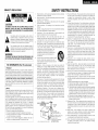
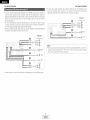
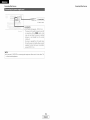
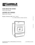
15. Outdoor Antenna Grounding - If an outside antenna or cable system
is connected to the product, be sure the antenna or cable system is
grounded so as to provide some protection against voltage surges
and built-up static charges. Article 810 of the National Electrical Code,
ANSI/NFPA 70, provides information with regard to proper grounding
of the mast and supporting structure, grounding of the lead-in wire to
an antenna discharge unit, size of grounding conductors, location of
antenna-discharge
unit, connection
to grounding electrodes,
and
requirements for the grounding electrode.
See Figure A.
16. Lightning - For added protection for this product during a lightning
storm, or when it is left unattended and unused for long periods of
time, unplug it from the wall outlet and disconnect the antenna or
cable system.
This will prevent damage to the product due to
lightning and power-line surges.
17. Power Lines -An outside antenna system should not be located in
the vicinity of overhead power lines or other electric light or power
circuits, or where it can fall into such power lines or circuits. When
installing an outside antenna system, extreme care should be taken to
keep from touching such power lines or circuits as contact with them
might be fatal.
18. Overloading
- Do not overload wall outlets, extension cords, or
integral convenience receptacles as this can result in a risk of fire or
electric shock.
19. Object and Liquid Entry - Never push objects of any kind into this
product through openings as they may touch dangerous voltage
points or short-out parts that could result in a fire or electric shock.
Never spill liquid of any kind on the product.
20. Servicing - Do not attempt to service this product yourself as opening
or removing covers may expose you to dangerous voltage or other
hazards. Refer all servicing to qualified service personnel.
21.
Damage Requiring Service - Unplug this product from the wall outlet
and refer servicing to qualified service personnel under the following
conditions:
a) When the power-supply cord or plug is damaged,
b) if liquid has been spilled, or objects have fallen into the product,
c) if the product has been exposed to rain or watefl
d) if the product does not operate normally by following the operating
instructions.
Adjust only those controls that are covered by the
operating instructions as an improper adjustment of other controls
may result in damage and will often require extensive work by a
qualified technician to restore the product to its normal operation,
e) If the product has been dropped or damaged in any way, and
f) When the product exhibits a distinct change in performance - this
indicates a need for service.
22.
Replacement Parts - When replacement parts are required, be sure
the service technician has used replacement parts specified by the
manufacturer or have the same characteristics
as the original part.
Unauthorized substitutions may result in fire, electric shock, or other
hazards.
operated only from the type
label. If you are not sure of
consult your product dealer
intended to operate from
the operating instructions.
12. Grounding or Polarization - This product may be equipped with a
polarized akernating-current
line plug (a plug having one blade wider
than the other). This plug will fit into the power outlet only one way.
This is a safety feature. If you are unable to insert the plug fully into
the outlet, try reversing the plug. If the plug should still fail to fit,
contact your electrician to replace your obsolete outlet. Do not defeat
the safety purpose of the polarized plug.
EXAMPLE
FIGURE A
OF ANTENNA
GROUNDING
_
"
AS PER NATIONAL
ELECTRICAL
CODE
_ANTENNA
LEAD
GROUND
CLAMP
I
I
IN
WiRE
DISCHAR®E
UNIT
810
_ANTENNA(NEC SECTION
_
20)
GROUNDING
CONDUCTORS
(NEC SECTION
BE0 2/)
_......_J_=
NEC
NATIONAL
ELECTRICAL
CODE
G ROU NSERVICE
D CLAMPS GROUNDING
POWER
ELECTRODE
SYSTEM
(NEC ART 250 PART H)
23. Safety Check - Upon completion
of any service or repairs to this
product, ask the service technician to perform safety checks to
determine that the product is in proper operating condition.
24. Wall or Ceiling Mounting - The product should be mounted to a wall
or ceiling only as recommended
by the manufacturer.
25.
Heat - The product should be situated away from heat sources such
as radiators, heat registers, stoves, or other products (including
amplifiers) that produce heat.
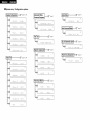
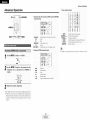
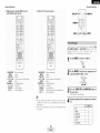
• System setup / Configuration
[Speaker Configurationt..... _
systeme
page38,39
w
I
_ @
"
_
÷
:+:F:_..,::,n i::
I Audio Delay t....................
pubwoofer Mode
[
CrossoverFrequency/ ....... _
page40
:i.:i:::i= [i:_¢.-_!
].._ :=
2
:i!;_,_
._i_
:i.].
_" _
:i.:'.!!i;
'._ i"io ,:::i
,_i_ i".io _..r=_
v.=
%.
"
:i.:C r., 0 _...,
e_....
÷]
E:ii!:.i
i-iz
i_
3
÷
_
W
:+::i!;,,ii!',._z_
,:::i.:
:i!;r,_
._i_
:i.].
%.
TestTone t.......................
%" ÷
:+:S ,, B .iii_
,:::i.:
_
° ÷[
:i.:'i li!::i!;'i '_,=.,"'
,.,_
_::,...
",..............
=::::
.::....
.,:..:
..........
,=.,......'
:.i.:=.[[;U i::=i.=.iO O i:' _iii!_..
Y _i! :E:
'.[[;U v. F. ,
hExt. In Subwoofer Level }----_
° eL
L
:i.:i:::iU '!::0
0 i".i
;"
page41
%"
% N
!i:.i_,_:'.-;
to Surround Mode }....... ;Z:_P page43
° ÷L
"
page43
&,
L .ilz_
v'.'.;;;i
e
:+:Ce n t: e_....
_
} _igital InAssignment }....... _
page43
_-'
:i.:ii!i;::.::
!:: = .,.T
,,"" '.i!;i.,.!"i"i !5,:::iEl _; '
poge42
Jm
"
[Delay Time t.....................
:.i.:i::_..o i_i:: L
:i.2 i: i::
_÷
:.i.:F:,....ont:i;;:
:i.:2.i:"t:
" ÷[
:.i.:C _iiiIi'_'!:: _i__..
:i.2 i: i::
_
C i::'
:i.:C !::iA X :?
i::i!.iX
:_.:
0 P i :i.
i) _..._
i)
:i.:fi F'i 2
T !,.i
..:_i=' page39,40
12
_"
E
LPower Amp Assignment }---_
:i.:C !::iFi',::',i
÷
_ Lr
_
:.i.::i!;LIi.. _.., i.
_deo
L r!_.,:.4::
Input Mode }............ _
page42
2D
_
÷
}÷
:i.:[)!...i [)
F:iu i:: o
I_
° ÷h
:i.:T'! i
F:iu i:: o
i 0 i: i::
'_
%
:i.: !..!!: !;?
F:iu 'i:: _:_
i. 2 i: !::
' _
:+:S u _.._..,R
._..
I
:.i.::i!;,, E:.iii_
,:::i.:: i....
i 0 i: i::
_"
° ÷[
:.i.::i!;,, E:.iii_c: i4 i:;i:
.%" ÷i
:.i.::i!;i._.!
"
" '::'':_..
@
" ÷1
"
I
,u
_
% _ I
:i.:i:::'= i:::i
rq F'
page43
:[[!;= El;._i_
C }:
_:::o
Getting Started
Getting Started
Remote control unit
Thanl< .,ou Tor ChOOSing tne DENON AVR-686 AV Surround Receiver This remarkable somoonem nas been eng leerea tc rarovide
superb surround sound stoning wlTr nome theater sources SUChas DVE )s well as provlalng outstanding high fidelity reproduction
3f v ur favorite music sources.
As this aroauct is orovlaea we recommend With an mmense arra of features
the contents
• tRig manua
before proceeding.
Accessories .........................................................................
2
Before using
....................................................................
Cautions on installation
.............................
2
2
Cautions on handling ..................................
Preparing the remote control unit ......................................
Inserting the batteries ............................................................
Operating range of the remote control unit ................
Part names and functions
From dar el
.....................................................................
2
2
3
3
men_ote
corltro
unit
................................................................
3
_-
l EaSy Setup and Operation
Easy setup flow .....................................................................
,_
Speaker system layout .....................................................
5
Speaker connections .........................................................
5. 6
Connecting a DVD player and monitor TV .........................
7
Auto Setup
Connecting a nucroonone ..........................................
8
Turning on me rower .....................................
8
Starting Auto Setup ......................................
9
About error messages .............................................
10
Playing a DVD with surround sound .................................
10
before you begin nooKup aria operation tnat .... review
Playback
Playing tne ir out source ...........................................
Listening
over
Connecting a TV/DBS tuner ...............................................
Connecting a video camera or video game ..............
Connecting the external inputs (EXT, IN) terminals ........
Connecting
a CD player ........................................
Connecting a VCR
....................................................
Connecting a tape deck, CD recorder or M D recorder ......
Connecting the antenna terminals .............................
13
Connecting the MULTI ZONE terminals
ZONE2 speaker OUTconnections ..................................
12
12
12
12
3
13
Connecting
the power supply cord .....................................
headphones
7
...............................................
Combirl ng me curremiv pla_ ing sound wltn me
desired image VIDEO SELECT) .............................
Selecting tne Tront speaKers ............................................
Checkinc tne curremiy playing p=ogram source ...................
-PUt mode .................................................
17
Surround
7
7
7
8
Playirlg audio sources CDs and DVDs
2-channe
DlaVDaCK
modes ...................................................
8
Dolby Pro Log c ]Ix IPro Logic ]][i mode .........................
9. 20
DTS qEO:6 mode .........................................................
21 22
Dolby Digita mode and DTS surround ........................... 22. 23
Nic _t mode ..............................................
24
Adjustir
g [ne audio dem v •.......................................
24
DENON original surround modes
Surround modes and me "teatures ..................
25
DSR surround sire Jlat or .............................................
26.27
Operating a component stored lr me
oreset memor_ .......................................................
32_34
_unch mrougn .................................................................
34
Multi zone music entertainment
system ........................
35
Remote cc strol unit o_)erations dunng
multi-sou rcE alavDacK ..........................................................
36
Other functions
_ecordmg wle drogram source
trecordlng the source currently being 11onltorec ...........
_ast tunct on memor_ ...................................
nitialization of the microorocessor ......................................
tne
Front display ....................................................
System Setup
Settir j the SE)eaKerConfig Jration ........................
Setting the Delav Time ...................................................
Settir ) me Subweofer Mode and
Crossover Freduenc_ ......................................................
Setting
Setting
Setting
Settinc
Setting
Setting
Setting
System
37
37
37
sound
duailtt
•..........
mode ..........................................
Channe Level ...............................................................
deTeat
Listening to the radio
Auto e_eset mernor,_ ........................................
Auto tuning ...........................
Manual tuning ........................................
Preset statlon_
.................................................................
Recalling ,)reset stations
28
28
29
29
30
30
30
1_.
5
1
L
28
ENGLISH
]
38
39
39 40
40
the Test Tone ........................................................
the Digital n Assignment
.....................................
me video nr)ut Mode
the Audio Dela.- ..................................................
the Auto Surround Mode .................................
the Ext. g Subwc _fer Level ................................
the Power Am ) Assignment ..................................
setup items and default values ..........................
Troubleshooting
Additional
Tone control settir g
• Tone
11
31
32
PiavDaCK using tne external in _ut /EXT. INI term nais .......... 16
Turning tne sound off temDoraruv IMUTINGI ...................... 16
• Adjusting
Cable indications .................................................................
The video conversion function .........................................
16
Operating DENON audio comDonems ............................
_reset memor -...................................................................
....................................................................
inf0rmation
SpeCifications
...................................................
........................................................................
List of preset codes
Ltl
42
42
43
43
43
43
_a
451
46_511
521
End of this manual
Getting Started
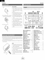
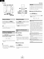
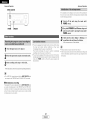
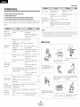
Check that the following
Getting Started
Noise or disturbance of the picture may be
generated if this unit er any ether electrenic
parts are included in addition te the main unit:
'_1}Operating instructions ............................
_2};Wa rranty .................................................
_3}}Service station list ..................................
'_4}Remote centrel unit (RC-1001) ...............
1
1
1
1
'_5}R6P/AA batteries ....................................
_6}AM leep antenna ....................................
_7.','FM indeer antenna .................................
'_8_Omnidirectional micrephone ...................
2
1
1
1
equipment using microprocessers
near a tuner or TV.
is used
i N
If this happens, take the fellowing steps:
• Install this unit as far away as possible
from the tuner er TV.
• Run the antenna wires from the tuner or
TV away from this unit's power supply cord
and input/eutput connection cables.
• Noise or disturbance
tends to occur
particularly when using indeor antennas or
300 _/ohm feeder wires. We recommend
using outdoor antennas and 75 _/ohm
coaxial cables,
Note:
Pay attentien
te the fellewing
before
using
this
unit:
• Moving the unit
Te prevent short-circuits er damaged wires in
the connectien cables, always unplug the power
supply cord and disconnect the connection
cables between all other audio cemponents
when moving the unit.
• Before turning the power switch on
Check once again that all cennectiens
are
correct and that there are not preblems with
the cennectien cables. Always set the power
switch
to the standby
pesitien
befere
cennecting
and discennecting
connectien
cables.
• Store
these
instructions
in a safe place.
After reading, stere this instructions
the warranty card in a safe place.
For heat dispersal, do not install
enclosure,
along with
that the
illustrations
in these
• Note
instructions
may differ from the actual unit
for explanation purposes.
• Switching the input source when input terminals are not connected,
A clicking noise may be produced if the input source is switched when nething is connected to
the input terminals. If this happens, either turn down the MASTER VOLUME control knob or
cennect cempenents to the input terminals.
V. AUX terminals
The AVR-686's front panel is equipped with V.
AUX terminals. Remove the cap cevering the
terminals when yeu want te use them.
O
@
@ O @
°O
@
this unit in a confined space such as a bookcase or similar
• Muting of PRE OUT terminals, PHONES jack and SPEAKER terminals.
The PRE OUT terminals, PHONES jack and SPEAKER terminals include a muting circuit. Because
ef this, the output signals are greatly attenuated fer several seconds after the power switch is
turned on or the input seurce, surround mode or any ether set-up is changed. If the volume is
turned up during this time, the eutput will be very high after the muting circuit stops functioning.
Always wait until the muting circuit turns eff before adjusting the w>lume.
°
@
• Whenever the power switch is in the STANDBY state, the unit is still connected to AC line
voltage.
Please be sure to turn off the power switch or unplug the cord when you leave home for,
say, a vacation,
The included remote control unit (RC-1001 ) can be used to operate not only the AVR-686 but other
remete control compatible DENON components as well. In additien, the memory contains control
signals fer other remote control units, se it can be used te eperate nen-DENON remote centrel
compatible products.
2
I
ENGLISH I
Getting Started
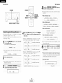
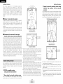
11 Remove
the remete
Getting Started
centrol
unit's rear
cever,
12} Set twe R6P/AA batteries in the battery
cempartment in the indicated directien.
Notes on batteries:
• Replace the batteries with new ones if the set
dees net operate even when the remote
contrel unit is operated nearby the unit. (The
included
batteries
are enly fer verifying
eperation.)
• When inserting the batteries, be sure to do so
in the proper directien, fellowing the "_" and
"O" marks in the battery compartment.
• To prevent damage or leakage of battery fluid:
• De not use a new battery tegether with an
old one.
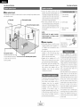
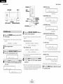
Fer details en the functions of these parts, refer te the pages given in parentheses
().
• Do not use two different types ef batteries.
• De not shert-circuit, disassemble,
heat er
13.:Put the rear cever back en.
dispose of batteries in flames.
• If the battery fluid should leak, carefully wipe
the fluid off the inside ef the battery
compartment and insert new batteries.
• When replacing the batteries, have the new
batteries ready and insert them as quickly as
pessible.
_]l Power ON/STANDBY
Power indicator
switch ................ (8)
......................................
Power switch ...................................
(8)
(8, 37)
_) Headphones jack (PHONES) ............... (17)
ANALOG
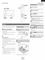
• Point the remote contrel unit at the remote sensor on the main unit as shewn in the diagram.
• The remote centrol unit can be used from a straight distance of approximately 23 feet from the
main unit, but this distance will be shorter if there are obstacles in the way or if the remete contrel
unit is not peinted directly at the remete sensor.
• The remote control unit can be operated at a horizontal angle ef up to 30 degrees with respect
to the remote sensor.
button ...................................
SPEAKER A/B buttons
ZONE2 button ......................................
(35)
_) MASTER VOLUME
_) TUNING
• (up)/¥
_) STATUS button
Display
STEREO button ................... (25)
_) DIRECT/STEREO
button ...................... (18)
• It may be difficult to eperate the remote control
unit if the remote sensor is exposed te direct
sunlight or streng artificial light.
• Do not press buttons on the main unit and
remete contrel unit simultaneeusly.
Doing so
may result in malfunctien.
• Neon signs er other devices emitting pulsetype noise nearby may result in malfunction,
so keep the set as far away frem such devices
as possible.
_t V. AUX INPUT terminals
..................... (12)
_) SETUP MIC jack .....................................
_) SURROUND
MODE button ................. (16)
SURROUND PARAMETER
button ...................................................
(_ SELECT knob ............................
ENGLISH I
,,,,,(29)
(17, 23)
indicator
(19)
(28)
(17)
INPUT mode indicator
i_) SIGNAL indicator
(22)
..................... (16)
......................... (18)
.................................
(18)
!_) BAND button ........................................
(29)
_) EXT. IN button ......................................
(16)
_) Remote
control sensor ..........................
INPUT MODE button ...........................
(16, 19, 28)
_]_ TONE DEFEAT button ..........................
3
(8)
(down)
_) OUTPUT indicator ................................
STANDARD/NIGHT
_) 5CH/7CH
buttons
..............................
DIMMER button ...................................
Master volume
button ........... (19-24)
...................... (28)
control knob ........ (16)
_) VIDEO SELECT button ......................... (17)
Preset station select buttons ....... (29, 30)
NOTE:
I
(18)
.................. (17, 37)
_) TONE CONTROL button
(3)
(17)
_) INPUT SELECTOR knob ....................... (16)
Getting Started
Easy Setup and Operation
For details on the functions
of these parts, refer to the pages given in parentheses
36)
";-
Iso..ouNo-o0
Ibuttons ................. (16,
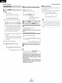
• This section contains the basic steps necessary to configure the AVR-686 according to your
listening room environment and the source equipment and loudspeakers you are using.
• For optimum performance, we recommend using the Auto Setup function.
• If you wish, you can set the various settings manually without using Auto Setup (_
page 38
41).
Remote control signal
transmitter ................... (3) I
I'ndioator
...............
'32
3 '1
IZONE2 buttons,,,,(34,
().
i
"
34) I
-h
i__i
! P!acing the speakers: _
!
Ibuttons
................. (16,32)|
(_
@
@
_
Connecting
tTuner system/System
buttons ................. (29, 34) I
__
_
th e
speakers,
j
!
"";_,_..........
.
_%_;;T':
.,,00 _,_:_
_Connect,ng
Mode selector switches
-
,,
................................
(8, 31)
I
"2222222222222222222v=_
..............................
SYSTEM
(31 _34)
buttons ................. (16, 36)
SETUP/SETUP
"_!'"
button ................... (33, 38)
_
A/ B
Cursor buttons
..........................
DiscSKP+ ,
_-<-
(9, 19, 33)
....................................
_
TEST TONE button
....................................
(=._
i_
....
IE_ [ON£
V,DEO
SELECT
button
................ (16_18)
PARAMETER/System
< Playing
CH SELECT/ENTER
button .....................(20, 28)
button ................... <19, 33)
"_
_
VIDE0 SE_
I
_IMME_
--
_PAK£
_
--_m",._-CmF_
_ _
I L;7
--
a DVD with
surround
i
"'-. _._,
SURROUND BACK/
RETURN button,,,(22,
33)
--
--
(17)
/
I
s0und.
Check of the measurement
Stere the measurement
result,
result in the memery.
h
J
J
DEcN_
ON
• The Dolby Surround Pro Logic Ill(x) Cinema or Music mode can be chosen directly by pressing the
CINEMA or MUSIC button on the remote control unit during playback in the Delby Surround Pro
Logic ]][(x) mode.
• The DTS NEe:6 Cinema or Music mode can be chosen directly by pressing the CINEMA er MUSIC
button on the remote control unit during playback in the DTS NEe:6 mode.
• The main zone output can be turned on and off with the MAIN button.
h_
}
!
__j',
', .....
(41)
SetUP.
(16)
h
1) Speaker Configuration
2) Delay ]1me
3) Channel Level
Starting the Auto
SURROUND
)_
ii_,
--_,,._,_."" ...........
MEMO
fi MUT,NGbutton,.
;:----_------_-*--:: _
STATUS/DISPLAY
button ............ (17, 23, 33)
buttons
_
(@/
Measurement of the speakers
in the listening position.
a mon,torh
and a DVD player.
4
ENGLISH I
Easy Setup and Operation
Easy Setup and Operation
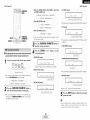
o Cennect the speaker terminals
with the
speakers making sure that like pelarities are
matched (@ with @, _ with _). Mismatching
ef polarities will result in weak central sound,
unclear orientation of the varieus instruments,
and the stereo image being impaired.
• Basic system layout
Tile following is an example of the basic layout fer a system censisting ef eight speaker systems
and a televisien meniter:
Center
speaker
system
"When
making connections,
take care that
none of the individual conductors of the speaker
cable come in contact with adjacent terminals,
with other speaker cable conductors, er with
Surround back speaker systems
the rear panel.
1. Loosen by turning
ceuntercleckwise.
H
2. Insert the cable.
3. Tighten by turning
cleckwise.
__
NOTE:
NEVER touch the speaker
terminals
when the power is on. Doing so could
result in electric shocks,
• Speakerimpedance
,'When speaker systems A and B are used
separately, speakers with an impedance of 6
te 16 _2/ohms can be connected for use as
front speakers.
• Be careful when using twe pairs of frent
speakers (A + B) at the same time, since
speakers with an impedance
of 12 te 16
_2/ohms in this case must be used.
• Speakers with an impedance ef 6 to 16
_/ohms can be connected for use as center
and surround and surround back speakers.
• The pretector circuit may be activated if the
unit is operated for leng perieds of time at
high velumes
when
speakers
with
an
impedance
lower
than
the
specified
impedance are connected.
r
Front speaker systems
Set these at the sides ef the TV
er screen with their front surfaces
as flush with the front of the
Surround speaker systems
screen as possible.
The pretecter circuit may be activated if the
unit is operated for long periods ef time at
high velumes
when speakers
with an
impedance
lower
than
the
specified
impedance (for example speakers with an
impedance
ef less than 4 _2/ehms) are
connected.
If the pretecter
circuit
is
activated, the speaker output is cut off. Turn
eff the unit's power, wait fer the unit te cool
down, improve the ventilation areund the
unit, then turn the power back en.
5
I
ENGLISH I
Banana plug
TgrhltCln°t kh:irs:1_: rt
<_:_
the banana plug.
This uni_ is equipped wi_h a high-speed
pretection circuit. The purpose of this circuit
is to pretect the speakers under circumstances
such as when the output of the power
amplifier is inadvertently short-circuited and
a large current flews, when the temperature
surrounding
the unit becomes
unusually
high, er when the unit is used at high eutput
ever a leng peried which results in an
extreme temperature rise.
When the pretectien circuit is activated, the
speaker output is cut off and the power
supply indicater flashes. Should this eccur,
please fellew these steps: be sure to switch
off the power of this unit, check whether
there are any faults with the wiring of the
speaker cables or input cables, and wait for
the unit to cool down if it is very het.
Improve the ventilation condition around the
unit and switch the power back en.
If the protection circuit is activated again
even though there are no problems with the
wiring or the ventilation areund the unit,
switch off the power and contact a DENON
service center.
Easy Setup and Operation
Easy Setup and Operation
• Connections
When making connections,
also refer to the operating instructiens
Center
Subwoofer
speaker
of the other compenents.
Surround speaker
systems
÷ To achieve Dolb¥ Digital
playback effect, use a unit
that can sufficiently reproduce
frequencies of under 80 Hz.
_--jiN
Connection termh_al
[_
for a subwoofer with
built-in amplifier.
_
@
(R)II
Front speaker
systems (B)
Front speaker
systems (A)
Precautions when connecting speakers:
If a speaker is placed near a TV or video
menitor, the colers en the screen may be
disturbed by the speaker's magnetism.
If
this should happen, meve the speaker away
to a pesitien where it does net cause this
effect.
Surround back
speaker systems
NOTE:
• When
using only ene surround
back
speaker, connect it to the left channel.
6
I
ENGLISH I
Easy Setup and Operation
Easy Setup and Operation
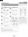
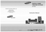
• For best picture quality (especially with progressive DVD and other high definition sources),
choose the component video connectk)n to your monitor TV. S-Video and composite video
outputs are also provided if your TV does not have component video inputs.
• To connect the video output from the DVD player to tile AVR-686, you only need to choose one
connection type. Component vide() connection offers the best quality (and is required for
progressive DVD playback), folk)wed by S-Video, while composite vide() offers the lowest picture
quality of the three connection types. For mere information about the video up conversion
function (r@P page 11).
• To connect the digital audio output from the DVD player, you can choose from either the coaxial
or optical connections, if you choose to use the coaxial connection, it needs to be assigned. For
more information about Digital input Assignment (_
page 42).
• Connect a non-DVD video disc player (such as a laser disc, VCD/SVCD, or future high definition
disc player) to the DVD/VDP terminals in the same way.
................
Monitor
COMPONENT
_,,,,,,,,,,,,,,,,I_1_
[]
VIDEO
.................
IN
S VIDEOIN
[]
........ DVD player
COMPONENT
@
TV
VIDEO
.......
_
OUT
@ _72°
...................................................................................
J
......._
O
Y
NOTE:
[]
_,,,_,,,,,,,,,,,_
@
• The component video input and/or output terminals may be labeled differently on some TVs,
monitors or vide() components (Y, PB, PR; Y, CB, CR; Y, B-Y, R-Y). Check the owner's manuals
for the other components for further information.
S VIDEOouT
[]
VIDEO
OUT
*"""""_[ii_
...................... 'O
[]
[]
e ...........................
!/,,,,,,_
AUDIO
OPTICALouT
OUT
•
/
÷ Audio signal flow is shown with white arrows; video signal flow is shown with gray arrows.
7
I
ENGLISH I
Easy Setup and Operation
Easy Setup and Operation
ON/SOURCE
POWER
Turn
MODEI-,,_J
SPEAKER
A
on your
subwoofel:
Turn on your monitor (TV).
Press the POWER switch.
-CURSOR
J= ON:
ON/STANDBY
c_.--SPEAKER
SETUP MIC
The
oovder
turns
on
ancI
t"e
inolcaTor
ic qTS
Set the POWERsNItcn to tnls oos [ion to turn rne oower on
ana off from the included remote comro
!
OFF:
The oo Jer turns off ano tne nalcator is off.
_- m,s oosmon, tne Dower cannot De Turnea on an(] off from
tne remote
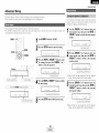
The Auto Setup function
of this unit performs
an analysis of the
speaker system to permit an appropriate automatic
l uonneCting
setting,
• Measurement
and setting
details
L:This
sets the speaker
connection,
polarity, and bass
reproduction ability.
,: This sets the delay time from each speaker corresponding to
the listening position.
_
/
a microphone
Connect
the
SETUP MIC
O
microphone
for
u. the truat
° .
_ o e
e e _
that you turn off the power of any air-conditioner, projector or
other equipment that may produce noise.
• De not stand between the microphone and speakers while
Setup to the
uf t]ze unit.
o _
_ _
e
e
ears.
and
the
NOTE:
• A loud test tone is output during the measurement. Please
consider
this
should you
be planning
night
time
measurements,
and consider not allowing small children
into the listening room at this time.
• The Aute Setup is not displayed
when "MUTING",
"HEADPHONE ONLY" is selected.
"_ Place tne mlcroDnone on a mooo or level surface.
8
I
switch
on the main
unit
on the remote
conn-ol
unit.
" Tuln
Oil
Press
the
On.
the
Jowel
SPEAKERA button
to turn
the speakers
Set the MODE 1 switch to "AUDIO"
(only when
operating
with the remote control unit).
Place the microphone
for Auto Setup at the actual
listening
position
which
will be at the same height
as your
unE
[.__]
©
It is recommended
Auto Setup is performed.
• Do not place any obstacles between the microphone
speakers. Also, be sure te point the speakers tewards
listening position.
paae]
'_
For accurate measurements
• Keep quiet during the auto setup procedure.
Auto
_@_e_
t3::This sets the volume that is output from each speaker.
ConTrol
Press the 0N/STANDBY
or 0N/SOURCE button
jack
UnIT
ENGLISH I
Easy Setup and Operation
Easy Setup and Operation
• Check the results of the speaker detection
Press the CURSOR <1button to start the Auto
Setup.
• Start
the
Example: 7.1-channel __'aTems
measurements
of eacn cnannel is Derforrrea as
0 _..J_i!_..]. O ._i_=:::i i:;i:_i!'!:: v. := ].
_ 3eaKer
NOTE:
TOIIO\&/S:
_ ress the CURSOR A or V button
to select
"Store". then press the CURSOR <3 button.
÷ 1: Or y the front soeaKers (A) are measured, front soeaKers
BI are nor available. Even f the front speakers (B) are
set. IRe setting
speakers
(A}
3nce
auTomatlcallv
SWltcres
measuremems
are
to the front
comr)letea
÷2: The SUDWoofer sDeaKer is measurea _wlce.
Store:
Store tl _ e cnecKea
AI
oarameTers
measurement
values
are sTorec
Cancel:
Cancel
÷ 3: Wh_ _ "ZONE2"
the checked
measurement
values
s selecTeo mls is nor alsDlavea
cage 43)
After each channeJ is measured, "Calculating" appears.
The aisDla_ ;w rcnes to tne sDea<er cnecK alsDlav
auTomatlca
retry
To confirm the results of the measurements,
remeasurement is
automatically performed.
Remeasurement is performed up to 2 times. During this time,
"Retry1 " or "Retry2" is displayed en the display.
...............
:'=
U
Subwoofer
Surround and Surround DaCK
From ana Center soeaKel
'_ Measurement
• About automatic
y
=.. : : ==.... = =.:=:
t
I
Disconnect
::" ::::, .:._ _.: i:., _.". _ ."..
"! .
..
the setup mic to finish Auto Setup.
!
• Measurement
is cancelled if the MASTERVOLUME control knob
is operated while the Auto Setup is performed.
• If the output volume and crossover frequency of your
subwoofer speaker can be changed, then set the volume to
halfway and the crossover filter to maximum
or switch off
the low-pass filter.
• The speaker configuration, delay time and channel level
measurement
values can be checked using the system
setup function (_
page 38 ~ 41).
9
I
ENGLISH I
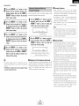
• When
measurements
have been
made using the
measurement
microphone, speakers with built-in filters,
such as a subwoofer, might be set to a value that differs
from the physical distance because of the internal electrical
delay.
Easy Setup and Operation
Easy Setup and Operation
• These errer displays may be displayed when performing Aute Setup measurement and the automatic measurements can not be
completed because ef the speaker arrangement, measurement envirenment, or other facters. Please check the follewing matters,
reset the pertinent items, and measure again.
• When there is too much noise in the room, the speakers may not be detected properly. Should this happen, perform the
measurements when the noise level is low, or switch off the power of the equipment that is producing the noise for the duration
of the measurements.
Disconnect
the microphone
Select the play (surround)
Start DVD playback.
_1};The speakers required fer producing suitable
reproduction have not been detected.
• The frent L or front R speaker was net
properly detected.
• Only one channel ef the surreund speakers
was detected.
Adjust
• Sound was eutput from the R channel when
only one surreund
back speaker
was
connected.
• The surreund back speaker was detected,
the surreund speaker was net detected.
C
r"_
,...:
._i_u i::
i
o ii
_ [:::=['_ ._i_:iii: _i!
...m:,.
C ._i_
u i:: i o ii
0 _...'
e _..1i.o .iii_
,::l
::1E::.::i t:
but
_2} The speaker polarity is cennected
in reverse.
• Check the polarity of the pertinent
speakers. Fer some speakers, this
display may be displayed
even
though the speakers are properly
cennected. If se, select "Skip,".
_.: When
cannot
• Set up the speakers se that their
position is farther away frem the
listening position.
• Lower the velume ef the subweofer
J
J
J
J
accurate
measurements
be
made due te the input level of the microphone
being too high.
speaker.
10
L
ENGLISH
J
the volume.
from
mode.
the unit.
Connecting
Connecting
Other Sources
Other Sources
The heokup diagrams on the subsequent
pages assume the use of the fellewing
eptional connection
With the AVR-686, the Video signal and the S-Video signal wMch
were inputted are mutually converted. And also the Vide() signal
and the S-Videe signal which were inputted are cenverted into a
higher quality.
cables (not supplied).
The flow of the video signals.
D
Analog terminal
(Stereo)
(White)
Q
=[_
(Red)
Q
4_:: _
r_
....
_,_c::::_
_(_
(Yellew)
¢_]=
Analog terminal
@
t
@
terloinals)
(Monaural, for subwoefer)
Ir_
@
(Orange)
_
_
(Coaxial)
_
Digital terminal
_r_=! Cemponent
.............
t
Coaxial cable (75 _/ohm
pin-plug cable)
(Green)
(Blue)
@
_
4:E_--._*_
(Red)
@
_._3
_,.'.._,_'_
1
%_
Compenent
@
_
(Y)
(PB/CB)
Q
(PR/CR)
video cable
[]
Optical cable (Optical fiber cable)
Audie signal
Speaker terminal
+
÷
m
m
IN
OUT
OUT
IN
IN
OUT
OUT
IN
Video signal
Speaker cable
NOTE:
• De not plug in the power supply cord until all connections have been cempleted.
• When making connections, also refer te the operating instructions of the other components.
• Be sure to cennect the left and right channels properly (left with left, right with right).
• Note that binding pin-plug cables together
er other neise.
(S-Videoterminal)
(Video
t_erminal}]
(Vide°
l_ rminal}
This unit's eutput
terminals
vide() terminal
(Optical)
[]
D
(Componeet
video
................ terminals)
(S-Videoterminal)
This unit's input
terminals
S-Video cable
Pin-plug cable
Digital terminal
,J_
s-video terminal
©
r_
I
Video cable (75 £_/ohm video pin-plug cable)
Pin-plug cable
D
ooo!
Video terminal
with power supply cords er placing them near a pewer transformer
11
I
ENGLISH I
will result in hum
Cautions on the video conversion function:
When the cemponent video terminals are used to connect the
AVR-6S6 with a TV (or meniteB projector, etc.) and the vide()
(yellew) or S-Videe terminals are used to cennect the AVR-686
with a VTR, depending en the cembinatien ef the TV and VTR
the picture may flicker in the herizental direction, be disterted,
be eut of sync net display at all when playing video tapes.
If this happens, cennect a commercially
available vide()
stabilizer, etc., with a TBC (time base correcter) function
between the AVR-686 and the VTR, er if yeur VTR has a TBC
function, turn it en.
Connecting
Other Sources
Connecting
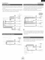
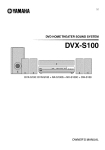
• For best picture quality choose tile component video connection to your TV or DBS tuner. S-Video
and composite video inputs are also provided if your TV or DBS tuner does not have component
video outputs.
• To connect the digital audio output from the TV or DBS tuner; you can choose from either the
coaxial or optical connections, if you cheese te use the coaxial cennection, it needs to be
assigned. For more information about Digital Input Assignment (_
page 42).
................................TV
[]
COMPONENT
• These terminals are for inputting multi-channel audio signals from an external decoder, or a
component with a different type of multi-channel decoder, such as a DVD Audio player, a multichannel Super Audio CD player, or another future multi-channel sound format decoder.
• The video signal connection is the same as that for a DVD player.
• For instructions on playback using the external input (EXT. IN) terminals (_
page 16).
DVD Audio-Video / ....
Super AudioCD player/
External decoder
................................
VIDEO
Other Sources
OUT
..........................................
::::: ...................................................
::::1::
[]
|
5 Ich AUDIO
.....
d:2
@ F=ONT
+_+@
_
O
[]
D .................
7_ _HHHHHHH_'_
OUT
O
R
RR
÷_:::::_b
@
O
CENTER
O
WOOFER
SUB
S VIDEOouT
[]
!{ ii i_i_: ?i' k' !f
_/s/s/s/s/sH_
0
VIDEO
OUT
....................C_
[]
OPTICAL
OUT
[]
[]
AUDIO
.... @O
÷_'s_*_*_*_*'_
OUT
L
....
OR
.
/
• With discs on which special copyright protection measures have been taken, the digital signals
may not be output from the DVD player, in this case, connect the DVD player's analog multichannel output to the AVR-686's EXT. IN terminals for playback. Also refer to your DVD player's
operating instructions.
Video camera /
Video game
[]
......
F'_
AUDIO
OUT
O
L
To connect the digital audio output from the CD player, you can choose either coaxial or optical
connection, if you choose to use the optical connection, it needs to be assigned. For more
information about Digital Input Assignment (:_
page 42).
[]
_,- @ .........................
b,,
_""_[_}_
_
O
...................
CD player ..................
VIDEO
OUT
AUDIO
\
I Lc_
[]
@'--,).,<+.<+_+g)
.....
@L
_/_+s,4_C_[]_ O
,
12
I
ENGLISH I
OUT
COAXIAL
OUT
Connecting
Other Sources
Connecting
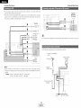
• For best picture quality choose tile compenent vide<) cennection to your VCR, S-Video and
compesite video outputs are alse provided.
• If you wish to perform analog dubbing frem a digital source, such as a DVD recorder te an analog
recorder such as a cassette deck, you will need to connect the analeg inputs and outputs as
shewn below, in addition to the digital audie cennections.
Tape deck / -C D recorder /
MD
[]
.......... Video deck
neise is generated,
Directien
station
ef breadcasting
,_,
OUT
FM antenna
_
AM Ioep antenna
(Supplied)
_'_
.I
@.
NOTE:
75 £_/ohm
COAXIAL cable
• When recording to a VCR recorder, it is necessary that the type of cable used with the
playback seurce equipment be the same type that is connected to the AVR-686 VCR OUTPUT
terminal.
Example:
A_,_Jo,?
out
meve the tape deck further away frem the source ef such noise.
An FM antenna cable plug can be connected directly te the unit.
AUDIO
recorder
...........
• If humming
[]
Other Sources
VCR IN --> S-Videe cable : VCR OUT -+ S-Videe cable
VCR IN _ Vide<) cable : VCR OUT _ Video cable
FM indeor antenna
(Supplied)
Greund
13
I
ENGLISH I
AM outdoor antenna
Connecting
Other Sources
Connecting
Other Sources
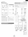
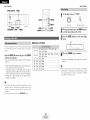
• AM loop antenna assembly
r
Connect to the AM
antenna terminals
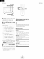
• When the pewer amplifier
is assigned te the ZONE2 output channel at "Power Amp
Assignment",
the surround back speaker terminals can be used as the ZONE2 speaker eut
terminals (z:_ _ page 35).
• The connections diagram below is an example for when the surround back speaker is assigned
te the ZONE2 stereo 2 channel.
1. Push the lever.
and take out the
connection line
In this case, surreund back speaker out can not be used fer MAIN ZONE.
Bend in the reverse
direction.
@
Subwoofer
a Antenna placed on
a stable surface.
Center
speaker
Surround
speaker
systems
2. Insert the cenducter.
Mount
/
b antenna
Hanging on
the a wall
_
3. Return the lever.
J
/,
Use the
installation hole to secure the antenna to a wall, etc
•
J
Note to CATV system installer:
This reminder is previded te call the CATV
NOTE:
• Do net
system installer's attention to Article 820-40
_f tha NFC whiah provir]ms gliidalinms
for
proper grounding and, in particular, specifies
that the cable ground shall be cennected to
the greunding system ef the building, as
close to the peint of cable entry as practical.
simultaneously.
• Fv_n if an _×t_rnal AM
net discennect the AM
• Make sure the AM
terminals de not teuch
panel.
÷ For instructions
en operatiens
connect
using the MULTI ZONE functions
(_
two
FM
antennas
,:_
ii! i!i
antenna is Hs_r], d_
loop antenna.
leop antenna lead
metal parts of the
page 35, 36).
F
Front speaker
systems (B)
Front speaker
systems (A)
ZONE2 speaker
systems
NOTE:
• The settings must be
changed to use this
speaker fer ZONE2
(r_ page 43).
I. ..................
14
I
ENGLISH
J
Connecting
Other Sources
Connecting
ACout,
e,,Wo,,,
]
AC 120 V, 60 Hz
AC OUTLETS
• SWITCHED (total capacity - 120 W (1 A.))
The power to this outlet is turned on and off
in conjunction with the POWER switch on the
main unit, and when the power is switched
between on and standby from the remote
control unit.
No power is supplied from this outlet when
this unit's power is at standby. Never connect
equipment whose total power consumption
exceeds 120 W (1 A.).
NOTE:
• Only use the AC OUTLETS for connecting
or other electrical appliances.
audio equipment.
Never use it for hair driers, TVs
15
L
ENGLISH
J
Other Sources
Basic Operation
Basic Operation
The signals being input to the external decoder input terminals
are played without
INPUT MODE
ANALOG
MASTER VOLUME
Press
SURROUND MODE
SELECT
(Main unit
Select
the
play
Remote control unit
(surround)
SUR_OUNO
_E
Main
•_
to select
the external
%
uniL)
to switch
input.
to the
aeslrea input mode (_
page 17, 18).
• The external input mode can be set for any input source, To
Na_cn waeo wnue listening to sound, select the input source to
Nnlcn tne vlaeo signal is connected, then set this mode,
• if the subwoofer output level is too high, set the "SW ATT."
surrouna parameter to "ON".
• When the input mode is set to the external input (EXT. IN),
the play mode (DIRECT, VIRTUAL SURROUND, STEREO,
STANDARD (DOLBY/DTS SURROUND), 5CH/7CH STEREO
or DSP SIMULATION) cannot be selected.
STEtfO
SELECT
%
INPUT
SELECTOR-
button
NOTE:
mode.
Example: STEREO
-SURROUND
MODE
EXT. IN
• Cancelling the external input mode:
Press the INPUT MODE or ANALOG button
Example: CD
INPUT SELECTOR
the
passing through the surround circuitry,
(Re tloLe
conuo
uHu
• In play modes other than the external input mode, the
signals connected
to the EXT. IN terminals
cannot be
leploduced.
In addition, signals cannot be output flora
channels not connected to the input terminals.
) seiec_ tne surrouna rroae _ nue aajustlng me surrouna
parameters, tone defeat or tone sonzroL gress the SURROUND
MODE button and then _Deraze zne selector.
-VOLUME
Start playback
on the selected
use this to turn off the audio output temporarily.
component.
MUTING
÷ For operating
Adjust
insTrucTions
manual.
(
IN
_0
Press
the
MUTING
button.
the volume.
............
INPUT
refer to tne comuonent's
]he volume levels
_-
olselayea
-(Remote controJunit
(Main unit)
on the
master volume level
slselav.
•_ The v }lume can De aa us_ea wEnln the range of -70 to 0 To
8 dB in STeDSof 1 dB. However. wnen tne cnarnei te el is
SeT as described (_3age
28). if the volurt-e for an
cqannei is set at + dB or greatei me volume cannot De
aaiustea up to 18 dB
aa usteato
'18dB
- mls case tne max mum volume is
Maximum value of channe leveY'.)
16
I
ENGLISH I
• Canceling the MUTING mode:
1 Press the MUTING button again.
2 Press the VOLUME button on the remote control unit, or
adjust the volume up or down via the front panel MASTER
VOLUME knob.
Basic Operation
Basic Operation
INPUT MODE
ANALOG
DIMMER
STATUS
The AVR-686 has an AUTO signal detection
mode that
automatically identifies the type of incoming audio signals, but is
also equipped with a manual mode that can be switched
according to the type of input audio signals.
• Selecting the AUTO, PCM and DTS modes
the INPUT MODE button.
Press
PHONES
SPEAKER
VIDEO SELECT
MASTER VOLUME
÷ The mode swltcnes as snown
MODE DuEon IS Dresse(]
AUTO_
are
Press
corresponding
speaker
B button
to turn
the
pair on.
connecieci,
•_ The front soeaker A. 3 settir _ can De also De cnangeu vvttn
the SPEAKERDuEon _n tne remote contro unit
NOTE:
.T
Drevem
excesswel
neanng
oss
re
qor raise rne volume
tnls moae. tne lvoes of signals being input to me alglta an(]
analog mpJt terminals for me setectea
"aut source ale
setectea ana tne program n me AVR-686's surround decoae
is selectea automatlca ¢ UDORDlaVDaCk. This mode can be
selected foral
noutsourcesotherthanTUNER
In
The Eresence
or absence of digital stgnals is aetecteo me
tne
algltal
irout
terminals
a 9 laentified
9na
aecoalng ana 91avDaCKare peal )rmea autorYlaTical, NEn tne
DTS. DuID'_ Digtal ul PCM 2 u al/ll_l bf_l_U) fc lldt, If nu
evel
;ignais
A!her usmg neaa[nones
]lgltal
3e
desired
the
VIDEO SELECT button
source
appears
]iH::U
repeatedly
until
the
on the displa?:
a vlaeo source otner tnan Tne
oDeratlons
In
aoollIOn,
are
the
also
CIISE
GISDla_
a
eu on
can
De
swltcnecl to check me unit s _peratln 9 status While playing
a source
playback:
by pressing the VIDEO SELECTbutton.
,'2_ Switch the program source to the component
the video input terminals,
connected
Press
to
the
DIMMER button.
"_ The display brightness changes in four steps (bright, medium,
dim and elf).
17
I
signal
IS
Delng
InpJt.
ire
analcJ
nDU[
termlnaE
are
coTe•
are being input
'4ote tnat no se ma'. De generatea wnen usmg tnis moae to
pta_ stgnals _Tner man PCM signals
DTS
ENGLISH I
exclusive DTS signa DtawacK moae :
Decoding ana ola DaCKare or J oerformed
are
• Using the dimmer function
• Canceling simulcast
Select"SOURCE"
to
PCM (exclusive PCM stgna DlavDacK moae_:
Decoding ancl DlaVDaCKare only Derformea wnen PCM signals
the STATUS button.
•_ DescrlDtlons 3f the units
[re
front panel
CIISDaV,
:!!!;O!J
R CE
÷ L se thiS SWIIC q tO monitor
aualo source.
Press
nout
use tnts moae to play Dolb_ Digital stgnals.
• Front panel display
Press
DTS
AUTO taut• moae,:
SPEAKER A or
the
_
f
l Selecting the front speakers
Connect
the headphones
to the PHONES jack.
• TI-e sneaKer OUlBUIis automaltcs . turned off when headonones
PCM
belOW eacn time the INPUT
Delng
" aut
when DTS signals
Basic Operation
•
Selecting
Basic Operation
the analog
• Input signal display
mode
NOTE:
• The "DIGITAL" indicator will light when playing CD-ROMs
containing data other than audio signals, but no sound will
be heard.
• DOLBY DIGITAL
Press the
ANALOG button to switch to the analog
input,
-nrl
SIGNAL
--
DIGITAL
-'8c
ANALOG (exclusive analog audio signal playback mode):
The signals input to the analog input terminals are decode d
and played.
o
÷ The "DIGITAL"
indicater
lights
when digital signals are being input
properly. If the "DIGITAL" indicator
• DTS
SIGNAL
does not light, check whether the
Digital In Assignment setup (_
page 42) and connections are correct
and whether
the component's
Nrl DIGITAL
\
o
NOTE:
• Input mode when playing DTS sources:
Noise will be output if DTS-compatible
CDs or LDs are
played in the "ANALOG" or "PCM" mode.
When playing DTS-compatible sources, be sure to connect
the source component
to the digital input terminals
(OPTICAL/COAXIAL) and set the input mode to "DTS".
/
.oc
• PCM
SIGNAL
power
.......................................
is turned on.
f]rl DIGITAL
O
O
• Input mode display
• STEREO mode
• In the AUTO mode
Use this mode to adjust the tone and achieve the desired sound
while watching images.
........................................................................
INPUT ........................................................................
Depending on the input signak
AUTO\_/
_OC
PCM
O
DTS
O
_
• In the DIGITAL PCM mode
INPUT
AUTO
PCM
o
o
INPUT
O
PCM
playback
modes
DTS
O
• In the ANALOG mode
_
Use this mode to achieve good quality 2-channel sound while
watching images, in this mode, the audio signals bypass such
circuits as the tone circuit and are transmitted directly, resulting
in good quality sound.
Press the DIRECT/STEREO bu_on on the main unit
or the DIRECT button on the remote control unit to
select the DIRECT mode.
INPUT
AUTO
PCM
DTS
o
o
o
Press the DIRECT/STEREO
button on the main unit
or the
select
• DIRECT mode
DTS
• In the DIGITAL DTS mode
AUTO
• The AVR-686 is equipped with 2-channel
exclusively for music.
• Select the mode to suit your tastes.
18
I
ENGLISH I
STEREO
button
the STEREO
on the
mode.
remote
control
unit
to
Basic Operation
Basic Operation
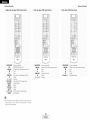
Press the SURROUND PARAMETER button
select the various parameters.
to
÷ The mode SWlTcnes as snown below eacn time me OU_TO_
IS dressed
-SURROUND
PARAMETER
-CURSOR >
ENTER-CURSOR<]--
• When the Cinema mode:
MODECINEMA_QNEMA EQ_TONE DEFEAT
DEFAULT
_SURROUND BACK-
-
• When the Music mode:
SURROUNDPARAMETER SELECT
4ODEMUSlC_TONE DEFEAT -SURROUNDBACK---
DEFAULTs--CENTERWIDTH_
DIMENSION_
PANORAMa_
• When the Game mode:
MODEGAME_TONE DEFEAT
*Tr. Dla
me PL]Ix mode
Configuration
se_tlngt
• To mav in the PL]][x mode
AmD Asslgr
se_ "S
BackSo
so or 2so"
set "Surround
a_ me
Bad
at me
Turn the SELECT knob, and press the CURSOR
<] or > button to select the optimum mode for
the source.
SoeaKer
MODEDOLBYP_ _ CINEMAEQ_ TONEDEFEAT
÷ Wher the "SURROUND
BACK" oarameter
Set "S. Back" at svstem setuE to "Small"
"='rePRO
j.
'_
qe mode
switches
LOGIC I1
.....
8 3 Shown
the
ilme
'__
,I(]ii[[j:=iiii[
]li]:_
,i.....
i:i::: :: .....JIl[Pr°(pr°(Pr°
LogicL°aic-°gl:
moae_
I[x G
I[x]IX
Cinema
ameMUSlC
moae,m°de'
_"=i....ii[::::
Turn the SELECT knob, and press the CURSOR
<:1 or
D
button
to
set
the
various
surround
parameters.
"_ W_ en the " SURROUND BACK" oarameter
Set 'S. Back" at svstem setuE [o "None".
is set to "OFF"
DTS NEO:(_
_._ iO!...
Play a program
DEFAUL---SURROUND BACK-
or "Large".
me DU_TOr
S oressec
DOLBY PLIIx
ON".
f you oo warn Tne oass an] _reme TODe ad=us_ed. _u=- off
the tone defeat mode.
I
eacn
is set to
Dolby
LIgnIs
Delow
• When the Dolby Pro Logic mode:
Power
semng
Press the STANDARD button
to select
Pro Logic
Ilx mode.
• The Dolbv Pro Log C n nalcalor ugnts
DEFAULT_ SURROUNDBACK
!:::'i....[n,
I (Pro _ogic I[ Cinema mode
")i]: .....
" i....iif "
I D'°
"_,)i) _::-
'
I(Pro Logic I[ Game mode
._ When the surround aararneTers are se_ using me autTons on
me ma=n Un=TS_OOouera_=ng me put,ons ]fter comp=eT=ng
me se_=ngs The se_=n9 s are automat=ca . finalized and Tne
normal
dlSDlaV
reaooears after several seconds
source.
"_ Fc _ operating
nsTrucl;ions.
"esdectlve comdonems.
"efer to me
manuals
Logic
II Music
mode,
• Cinema
EQ setting:
of me
Press the SURROUND PARAMETER button
select the surround
parameter
mode.
to
'If
:
-.._.=_::: _,=,, _::,-,
.....
(Dolb_ Pro Logi : mode
19
I
ENGLISH I
': ! !..ll:::i'l i:::i l:::!::i 0 _::'i:
I
Basic Operation
• PANORAMA
Basic Operation
setting
Press the ENTERbutton to finish the surround
parameter mode.
/
-= i...i !'d i i !_. =...=:.= =...= =i_=',"
• When
• DIMENSION
setting
rY_aKing oarameter
reguls
}ondlllOn
mressed
and the setting
settings,
_everal
tn
• CENTER WIDTH
..:=_
i:=
dlSDla_
after
De ceml
• Surround parameters
i!. _
tne
seconds
The
=/=_
:.=._
....
not
• TONE DEFEAT setting
BACK
i7!-'i-
.
SPEAKER
"=
televlslen
of
as
Sotlmum
snows
and
stere,
music
and
stereo music seurces.
offers
_rlooe
orldlna
D.,
LOgiC
IRe
"
same
case
IRe
roousl
source
surround
cenienl
s
dUallIV
Select one of the modes
Game
• Panorama Control:
i:ip,.]
i
Music
• D. COMR setting
nclucle tne
effect wlm
Tills contrel acl usts tne center irlage sc it F<lavDe leara onlv
...... IRe center speaker
on
from the left/right speakers as
C "" i:"
i. -"_
i: _
_ ]!
a onantom
ueg ees
The contr
mage
-_ Trom al tnree Trent soeaKers t
can De set
Ir
8 steps from 0 to
÷ This oarar'neter is 31solaved during DOLBY DIGITAL E avoacr.
• DEFAULT setting
l
"Prc Leglc
Tills sontr gradually adj SIS tile seundfield elmer towards
the front or tewards IRe rear.
The centre can De set In - 8teDs from 0 t 6
• Center Width Control:
ii..
: ..........
:inema"
This mede extends tne front stereo mage t,
surround soeaKers Ter ar excmng wraoarounu
sloe wal
aagmg.
Select
OFF" or ON
• Dimension Control:
setting
'i '.!
_
:;-_-'_
_oglc
was
The Game mode is for playing games. The 3ame mode can onw
De usea With 2-channel addle sources
i ii!".ii"
• SURROUND
>re
processing
to tne
outien
_1_
o programs encoded in Dolbx. Surreund
The Music
_eae s recemmended
_""
surreuno-encoded
sst
letec
Pro Logic ]Ix and Pro Logic M Mode:
The Cinema mode s fer use wltn ste[ee
setting
return
.
me
..= ....
..= ...i..I _
i..ii
÷ Select "YES" to reset to the factor'_ Jefaults
20
L
ENGLISH
J
varying
Basic Operation
Basic Operation
STANDARDINPUT MODE
SELECT
• CINEMA
EO setting:
iQ C @!
INPUT
SELECTOR-
iGe bE
-: i !..JJ:::
N i:::i J:::
!:} {} _::'_:
ie55j
• CENTER IMAGE setting
-SURROUND
PARAMETER
--CURSOR
ENTERCURSOR
q-
STAN!ARD
INPUT SELECTOR
,?.
[ 8= 8 _
--SURROUND
BACK
SURROUND PARAMETER
8 ,,3 _
i. ,,8
• TONE DEFEAT setting
INPUT MODE.........
i i iP.ii"
Press
select
Press
STANDARD button
NEO:6 themode.
÷ The moc.e switcnes
s oressec
to select
the
DTS
the SURROUND PARAMETER button
the various
parameters.
to
• SURROUND
-_ The moae SWltcnes as snown DelOVVea :n time Tne ouIIon IS
Dressea.
-.= ....
i._b" i" .
I
..,
i.#{H
BACK SPEAKER setting
•
I
"i
as snown below eacn time tne Dultor
• When the Cinema mode:
DOLBY PLIIx
DTS NEO:6
• D, COIVIP, setting
-_ MODECINEMA_ CINEMAEO_TONE DEFE/xT
DEFAULT_ SURROUNDBACK
! .......
=When the Music mode:
- MODEMUSC-
Press
the surround
SURROUND
PARAMETER
select the
parameter
mode. button
CENTERiMAGE _TONE DEFE/xT
÷ This parameter is al;played during DOLBY DIGITAL DiavDacK.
DEFAUL-_SURROUND BACK-
to
-_ _ _ou a• want tne Pass ana treble to De actjusteo, turn off
the tone defeat moae
Turn
< or the
D
Turn
SELECT
press the mode
CURSOR
< or the
_> button
to knob,
select and
the optimum
for
the source.
I
=.
.
k.
::= = = .:
0r F
SELECT
knob,set
button
to
and
the
p_iess,
_arious
• DEFAULT setting
I
the surround
CURSOR
parameters.
'_ Select "YES" to resel to tne factory defaults
•_ When me surrc una parameters are set us,rig lne DUI_OnSOrs
[ne main un,_. stop operating tne buttons after corco,etmg
me settings. The settings are aulomatlca / finalizea ana tne
normal
alaDlaV
reappears after several seconds,
J
21
I
ENGLISH I
f
Press the ENTER button
parameter mode.
to finish
the surround
Basic Operation
• When
Basic Operation
TlaKIn _ parameter
regular
Dressea
settings,
ule alspla¥
will
:enaltlen
several
seconas
atter rne
ana the setting
.
De COn oletea
ast
• Surround parameters
return
t
DUIton
Press the INPUT MODE button
mode to "AUTO"
or "DTS".
tne
to set the input
• D=COME setting
was
3
5)
Press
STANDARD button
the
STANDARD
(Dolby/DTS
to
Surround)
select
! .......
the
0 i" F
mode.
÷ This Dara _neler ISal splayed during DOLBY DIGITAL DlavDacK
DTS NEO:6 Mode:
• Cinema:
This
moae
s
otlmun"
TO alavmg
movies
Decoding
s
DerTormec wire emDnasls on seDaratler
oerfermance
ro
achieve me same atmosonere wffn 2-channe seurces as wlm
6,1-channel seurces
This noae
s effective
tor playing sources
ecoraea
convemlonal surreuna fermats as we
because the _-t nase
cor_-3enent is asslgnea mainly tO me center cnanne 'C) _na tne
reversea
Dnase
con-oenen] to rne ;urrouna (SL 3F ana SS
cnannels
• Music:
This
_()ae
Play a program
source
with the _
or P3_
symbol.
• The DOID'_Digital nalcatol gnts
DnDIGITAL
wner olaying Uolby Uigita
20 C -_lgnts
........
SUltea
[Tlaln
Tot
playing
n]uslc
The
front
cnanne
Dlavlng DTS sources,
_0_.---
• TONE DEFEAT setting
÷ Operate the SURROUNDBACK button
[o SVWTCnSurround Back CH ON/OFF
DUTtOn
SURROUND
8._K
-,0,--
.........
i i iP.ii"
ugnts
O.Otc
The center
image
center cnanne
.0: default 0.3 :
oarameter
"- me
Tor aajustlng
Press the SURROUND PARAMETER button
select the various parameters.
DT,c NEe:6
MUSIC
expansion
mode
..,
i._ {'.i
BACK SPEAKER setting
"= r"=
earar
eter
swEcnes
3s snown
belOW
I
to
=;
iq
" "_:' .:"
U i"
eac _ Tim@ tne
............
DUttOn IS eresseo
tne
...=....
i._b" i" .
IS or
• SURROUND
,_" The
CENTER IMAGE
]
Llgnts
FL and FR) signals bypass tne aecoaer ana are Dlavea alrectl
sc mere s qo
ss of souna ]uauw. ana tne effect OT tne
surrouna signals output Trom me center C ana surrouna SL
SR ana SB enannels aaa a natural sense }T exoanslon tc tne
souna field
3 .:!!!
!.
• The DTS indicator ugms .vner
• The S JRROUND BACK indicator
Ignts wnen! qe SURROUNDBACK
s
• LFE setting
_,:*i
]]'-:
_":=
11"
-.
_,E_
nas Deen
-_ C NEMAEQ_ D.COMP._ LFE_- TONEDEFEA
_
aaaea
DEFAULT
_
D01by Digital mode and DTS surround
_ (only with aigital input}
set to digital
42).
l
(COAXIAL/
SURROUNDBAO
• DEFAULT setting
SELEC_OF
÷ Select "YES" to reset to me factory defaults
parameters.
; uressea
7
I
Press
the
parameter
ENTER
button
to finish
the
surround
mode.
DVOIVDP
(_
Main unit}
I
' Turn the SELECTknob. and press the CURSOR
] or D button to set the various surround
÷ The mode swEcnes as snown De OW eacn tlnqe me button
Example: D\ D
NPUT
"_: .......
'_ This oarameter is alsDlaved during DOLBY DIGITA_ olaveac¢
-_ If .ou ao want me pass ana treble to De aajustea, _urn off
the tone defeat mode
Select
an input
source
OPTICAL)
(_
page
_
• tne
Remote
"
control
I
• CINEMA EQ setting:
unit
:: i,! !::i
!:: i:i
r"i _::'_::'
22
L
ENGLISH
J
• When mahn_ [)arameter settings tne alsDla'_ _ml return te tne
regular cenamer severa ;econas afte me lasl DUttOn
was
oressea ana the setting .
r)e con oletea
Basic Operation
•
Surround
parameters
Basic Operation
_3_
CINEMA EQ. (Cinema Equalizer):
The Cinema EQ function gently decreases the level of the
extreme
high frequencies,
compensating
for overly-bright
sounding motion picture seundtracks. Select this function if the
sound frem the frent speakers is tee bright.
This function only works in the Delby Pro Logic ]][x, Delby
Digital, DTS Surround and DTS NEe:6 modes. (The same
contents are set for all operating modes.)
• Dialogue normalization
SB CH OUT (Surreund Back):
(1) MultFchannel
• OFF:
source
Playback is conducted
speaker.
• NON MTRX:
without
using
the
The same signals as these of the surround
output from the surreund back channels.
• MTRX ON:
surround
channels
back
are
D.COMP. (Dynamic Range Compression):
Motion picture soundtracks have tremendous dynamic range
(the contrast between very soft and very leud sounds). For
listening late at night, or whenever the maximum sound level is
lower than usual, the Dynamic Range Compression allows you
to hear all of the sounds in the soundtrack (but with reduced
dynamic range). (This only works when playing program
sources recorded in Dolby Digital or DTS). Select one of the
four parameters ("OFF", "LOW", "MID" (middle) er "HIGH").
Set te "OFF" fer normal listening.
The surround back channel is repreduced using digital matrix
processing.
• ES MTRX:
LFE (Low Frequency Effect):
This sets the level of the LFE (Low Frequency Effect) sounds
included in the seurce when playing pregram sources recorded
in Delby Digital or DTS.
If the sound preduced from the subweefer sounds disterted
due to the LFE signals when playing Dolby Digital or DTS
sources when the peak limiter is turned eff with the subweefer
peak limit level setting, adjust the level as necessary.
Program source and adjustment range:
1. DelbyDigital:
-10dBte0dB
2. DTS Surround: -10 dB to 0 dB
decoder and the surreund back channel is repreduced.
• PL]][x Music:
When playing DTS signals, the surreund back signals underge
digital matrix precessing for playback.
• ES DSCRT:
When a signal identifying
the source as a discrete 6.1=channel
source is included in the DTS signals, the surround
signals included in the source are played.
• PL]][x Cinema:
Processing is perfermed
Processing
back
with the Cinema mode of the PL]][x
is perfermed
with the Music mode of the PL]][x
decoder and the surreund back channel is repreduced.
(2) 2ch source
• OFF:
Playback is conducted witheut using the surreund back speaker.
• ON:
Playback is conducted
using the surreund back speaker.
÷ When DTS encoded movie software
is played, it is
recommended
that the LFE LEVEL be set to 0 dB for
correct DTS playback.
'_ When DTS encoded music software
is played, it is
recommended that the LFE LEVEL be set to -10 dB for
correct DTS playback.
TONE:
This enables tone control. This can be set individually fer the
separate surround modes ether than DIRECT mode.
23
L
ENGLISH
]
The dialog nermalizatien functien is activated autematically when
playing Dolby Digital program sources.
Dialog nermalizatien is a basic function of Delby Digital which
automatically normalizes the dialog level (standard level) of the
signals which are recorded at different
levels for different
program sources, such as DVD, DTV and ether future formats
that will use Dolby Digital.
These contents can be verified with the STATUSbutton.
: :=,,. :,,. ,...=,,,
The number
currently
level.
indicates
:
.....
the normalization
playing program is normalized
level when
the
to the standard
Basic Operation
Basic Operation
STANDARD-
r P!ay a program source (DVD, etc.),
r
INPUT
SELECTOR-
Press the CURSOR A bu_on to switch t0 the
audi0 delay adjustment display:
Press
ENTER-CURSOR
INPUTMODE-
When listening at night or at lower volumes,
improves listenabiiity.
the night mode
Press and hold the NIGHT button for several seconds
t0 enter the night m0de,
• Canceling night mode:
Press and hold the NIGHT button again.
• The night mode only works when playing program
recorded in Delby Digital or DTS.
•_
Select the input source.
Example: DVD
NPUT
SELECTOF
DV_
O
Main
unit
'E_emote
V_)F
control
Un[l
Press the INPUT MODE button to set the input
mode to "AUTO".
3
Select Dolby/DTS Surround.
S_AN_A_D
Main
ST_NI_t0
unit
rE{emote
24
I
CURSOR< or D button
to set the delay
÷ With a movie source, for example, adjust so that the
m0yement of the actor s' !ips is synchr0nized with the sound:
_]#]({ ) {][i([ )
• When watching a DVD or other video source, the picture on the
monitor may seem delayed with respect to the sound, in this
case, adjust the audk) delay to delay the sound and synchronize
it with the picture.
• The audio delay setting is stored separately for each input
source.
• This adjustment carl be performed with the system setup
(_
page 43) or from the remote control unit, as described
below.
sources
the
ENGLISH I
control
unli
• The audio delay setting does not apply when playing in the EXT.
IN mode or in the analog input direct or stereo mode.
Basic Operation
Basic Operation
This unit is equipped with a high performance DSP (Digital Signal Processor) which uses digital signal processing to svntheticallv
recreate the sound field. One of 7 preset surround modes can be selected according to the program source and the parameters can
be adjusted according to the conditions in the listening room to achieve a more realistic, powerful sound.
1
The front left channel signals are output to the surround and surround back left channels, the front right
channel signals are output to the surround and surround back right channels, and the in-phase component
of the left and right channels is output to the center channel. Use this mode to enjoy stereo sound.
2
Select this when watching
3
Use this mode to achieve the feeling of a live concert in an arena with reflected
directions.
4
This mode creates the sound field of a live house with a low ceiling and hard walls. This mode gives jazz
averv vivid realism.
5
Use this to enjov video game sources.
monaural movies for a greater sense of expansion.
sounds coming from all
Select this to emphasize the sense of expansion for music sources recorded in stereo. Signals consisting
of the component difference of the input signals (the component that provides the sense of expansion)
_recessed for delav are output from the surround channel.
Select this mode to enjov a virtual sound field, produced from the front 2-channel speakers or headphones.
÷ Depending on the program source being piaved, the effect mav not be verv noticeable.
In this case, try other surround modes, without werrving about their names, to create a sound field suited to your tastes.
NOTE: When plaving sources recorded in monaural, the sound will be one-sided if signals are only input to one channel (left or right),
so input signals to both channels, if you have a source component with eniv one audio output (monophonic camcorder, etc.)
obtain a "Y" adapter cable to split the mono output to two outputs, and connect to the L and R inputs.
• Personal memory plus
This set is equipped with a personal memorize function that automatically memorizes the surround modes and input modes selected
for the different sources. When the input source is switched, the modes set for that source last time it was used are automaticallv
recalled.
÷ The surround parameters,
each surround mode.
tone control settings and playback level balance for the different
output channels are memorized
25
L
ENGLISH
J
for
Basic Operation
Basic Operation
• When the MONO MOVIE,
and VIDEO GAME mode:
-SURROUND
MODE
ROCK ARENA,
JAZZ CLUB
• D• COMP.setting
-ROOM SIZE_ EFFECTLEVEL_TONE DEFEAT
!.......
0 i" F
DEFAULT_SURROUNDBACK• When the MATRIX mode:
÷ This oarame_er ,s OlSOlavea during DOLBY DIGITAL DlaVDaCK
--_
-
DELAY_TONE E-FEAT
• LFE setting
DEFAL_T_SURROUND BACK_
• When the VIRTUAL mode:
TONEDEFEAT_
-SURROUND
PARAMETER
-CURSOR >
ENTERCURSOR
<I-
"_ '_ you ao wanT me Dass ana
the tone defeat moae
!
DEFAULT
treble
tc
De
aajustea
• To operate the surround mode and the surround
parameters from the remote control unit
÷ This parameTer ,s also,avea aunng DOLBY DIGITAL ana DTS
Press
various
the SURROUND PARAMETER button
the various
parameters.
the
CURSOR
parameters.
<1 or
D button
• ROOM SIZE setting:
Select
the
surround
mode
for thc
input
turn o"_
DlavDaOK.
Press
select
r
5 .::!!!
channel.
_
,.,,,.,,
set
• TONE DEFEAT setting
.........
i i iP.ii"
the
• SURROUND
,,,M
::=. .....
to
to
,......,, _
5iZE
......
...=....
i._b" i" .
.i.}[q
BACK SPEAKER setting
I
ME_....
_
I
,.,I ........
• EFFECT LEVEL setting
÷ This oarame_er ,s O,SDaveo ourmg DOLBY DIGITAL playback
Remote controJ unit
._ The surrouna moae SWltcnes
" the following
Time me DSP SIMULATION DuEon ,S Dressea:
oraer eacr
-.i:i
! i,..ui.,.i
i._
- MONOMOVIE_
MATRIX-
i.
• DEFAULT setting
.
::_i
ROCKARENA
VIDEOGAME-
• DELAY TIME setting
JAZZCLUB
Press the SURROUND PARAMETER button
enter the surround parameter setting mode.
'_ Select "YES" to reset to the factory defaults
to
•.b===:.:: _
::
Press the ENTER button to finish the surround
parameter mode.
•_ The surrouna parameter swltcnes in me following oraer
eacn t,me :he SURROUNDPARAMETERDuEon S Dressed for
the different surround modes.
• When making parameter settings, the display will return tD the
regular condition several seconds after the last button was
pressed and the setting will be completed.
26
I
ENGLISH I
Basic Operation
Basic Operation
TONE CONTROL
SURROUND MODE SELECT
iii i i?: i:i
CHSELECT/ENTER
CURSOR4-
-CURSOR >
:Z':Z;_:fi_i_i, _:_i_!_i
_
SURROUND PARAMETER
TONE DEFEAT
• Operating the surround mode and the surround
parameters from the main unit's panel
Turn
the
mode.
'_ When turned
SELECTknob
to select
the
Display the parameter you want to adjust, then
turn the SELECTknob to set it.
surround
• When making oarameter se_tings, the display will return to the
egu_u ;ondltlon
several seconds after the last butten was
dressed and _ne seating will be cempleted.
ClOCKWISe:
DIRECT - STEREO_ DOLBYPROLOGIC]Ix
• Surround parameters
-- MONO MOVIE+ 5CE7CH STEREO_ DTSNEO:6ROCKARENA_ JAZZCLUB_ VIDEOGAME
--
ROOM SIZE:
This sets u_e size or _ne seuna field.
RTUALSURROUND_ MATRIX
•_ W nen turned cob
There are five seatings: "small",
"meal.s" (medium-small),
_ealum
mea
(medium-large)
and "large".
"small"
recreates a small seuna field, "large" a large sound field.
qierclocKwlse
DIRECT-- STEREO- DOLBYPROLOGICIx -
EFFECT LEVEL:
MONO MOVIE-- 5CH/TCHSTEREO- DTSNEO:6
--
ROCKARENA_
JAZZCLUB_ VIDEOGAME
_)C_
I T;_AL_uRZRo(U_JD:Mi_Ep)yb,i_
i-
_4_
This sets die streng_n of the surround effect.
Theleve
car Dese_ _ 15 steps frem 1 te 15. Lewer the level
j
÷ To select the surrouna moae vvnue aajus_lng me surrouna
garameters
tone defeat
or tone comrok
Dress me
SURROUNDMODE button, then operate me selector
• IRe
sound
seems
distorted
DELAY TIME:
The aela Dme can _e set within the range of 0 te 11 0 ms only
n _ne ma_nx meae.
TONE CONTROL:
Press and hold
button
to select
in the SURROUND PARAMETER
the parameter
you want to set.
This car
DIRECT
De se_ nawlaua y for each surreund
÷Tne
_arameTers Nnlcn can De set differ for the differem
surround modes are alsDlavea, Refer te "Surround modes
ana Barameters" ( L_= Page 51).)
27
I
ENGLISH I
mode except
Basic Operation
Basic Operation
You can adjust the channel level either according to the playback
sources or to suit your taste, as described below.
• Adjusting the sound quality (tone)
The tone control function
Press
the
will not work in the DIRECT mode.
•_ The tone svv _cnes as follows
DUTTOn
4
TON E CONTROL button.
eacn t, me me TONE CONTROL
BASS _
•_ -he channel SWltcnes as snow[] belOW eacn time tne button
TREBLE
Turn the SELECTknob to adjust the level of the
bass or treble.
tne
the speaker
s bresseu
IS oressec
•_ To hcrease
Press the CH SELECTbutton
to select
whose
le_el'_you want to adjust.
Bass
or
treble:
Turn me contro 31OCKWlSe. (The bass or treble
ncreasea uo to +12 dB in stebs of 2 dB.)
÷ To aecrease me bass Drtreble:
aouna
can
be
Tu'- me control counterc,ocKw,se
The bass orTreb,e souna
:an be aecreasea down to -12 dB in steos of 2 dBd
Press the CURSOR <I or _> button to adjust the
level of the selected speaker.
÷ The aefault setang of the cnannel ,eve, s O dB.
"_ The level of the selec_ea speaker can be aa ustea w,mlr
• Tone defeat mode
f vo[ ao not want me [)ass ana t[eble to be aa ustea, turn
tone defeat mode.
•_ C/hen the surrouna EaCKsbeaKer seTtlr g ,s set to "lsb" for
"Sbeaker Configuration". this s set to "SB".
"_ "SB" appears onlv when the "Power AmP Assign." setting
Sthe surrouna DaCKmoae
" tne
me
range of +12 to -12 dB bv Dressing me CURSORbuttons
"_ The SW channel level can be turned off by decreasing it one
÷ The signals do not pass through the bass and treble
adjustment circuits, thus resulting in higher quality sound.
28
L
ENGLISH
J
Basic Operation
Basic Operation
INPUT SELECTOR
PRESET
1
I
Set the input source to "TUNER".
INPUT SELEG OR
TUNEt
%
TUNER
(Main unit
ON/STANDBY
BAND
TONING
::{emotecontrol unib
"Watching
the displa);
BAND button
select the desired
band press
(AM the
or FM).
to
Press
mode. the MODEbutton to set the auto tuning
ignts
• DEFAULT SETTINGS
This unit is equipped with a function for automatically searching
for FM broadcast stations and storing them in the preset
memory.
Hold the PRESETA button
Switch on the main unit.
*The unit au!omatically
stations
and press the POWER
begins searching
for FM broadcast
'_ When the first EM broadcast station is found, that station is
stored in the preset memory at channel A1.
Subsequent stations are automatically stored in order at
preset channels A1 to AS, B1 to B8, C! to C8, D1 to DS, E1
to ES, F1 to F8 and G1 to G8 for a maximum of 56 stations.
÷ Channel AI is tuned in
operation is completed.
after the
auto
preset
/
,::,!_o_,...,.,., :-,:,.". '._!..
A1 ~ A8
87.5 / 89.1 / 98.1 / 107.9 / 90.1 / 90.1 /
90.1 / 90.1 MHz
B1 ~ B8
520 / 600 / 1000 / 1400 / 1500 / 1710 kHz,
90.1 / 90.1 MHz
Cl ~ C8
D1 ~ D8
90.1 MHz
90.1 MHz
E1 ~ E8
90.1 MHz
F1 ~ F8
90.1 MHz
G1 ~ G8
90.1 MHz
"_ Automatic
funea
searching
Peg
/S
then STODSwRen I
station
iF
• When in the auto tunm£ mode on me FM r)ana the "STEREO"
nalcator iig [S on the alsDla wRen a stereo broadcast
s tuned
At open freauencles
rne noise s mute(] and me TUNED"
and STEREO nalcatersturn
_
memory
• if an FM station cannot be preset automatically due to poor
reception, use the "Manual tuning" operation to tune in the
station, then preset it using the manual "Preset memory"
operation.
• To interrupt this function, press the 0N/STANDBY switch.
29
I
Press the TUNING (+) or (-) button.
ENGLISH I
Basic Operation
r
Basic Operation
et the input
source to "TUNER".
Use the "Auto
tuning"
or "Manual
tuning"
operation
to tune in the station to be preset in
the memor):
Watching the display, press the BAND button
select the desired band (AM or FM).
Press
mode. the MODE button
to set the manual
to
Press the MEMORY button.
tuning
Press the SHIFT button
memory block (A to G).
÷ Checl mat me OISDlaV'S
"AUTO" indicator turns off
Press the
the desired
'_ Tile freauenc',
"/ela -
TUNING(+)
or (-)
station.
changes
COmlnuous
button
.
Nnen
to tune in
me
DuItor
S
• When the manual tuning mode is set, FM stereo broadcasts are
received in monaural and the "STEREO" indicator turns off.
and
select
Press the PRESET (+) or (-) button
desired preset channel (1 to 8).
Press
* Store
the MEMORY button
the statior
q the areset
the
to select the
again.
memory.
• To preset other channels, repeat steps 1 to 4.
A total of 56 broadcast stations can be preset -(channels 1 to 8) in each of blocks A to G.
Watching
the disPlaY , press
the
select the preset memo=_ blocL
Watching the display, press the
or V (--)button
to select
the
channel.
30
L
ENGLISH
desired
J
8 stations
SHifTbu.on to
PRESET i (+)
desh'ed
preset
Advanced
Advanced Operation
OFF-
NUMBER-
3. Tuner system buttons
1. CD player (CD), CD recorder and MD recorder (CDR/MD)
system buttons
--0N/SOURCE
®
-_® C ®!
MODE1-
--MODE2
_11_1,I_1_
•
I_
: Manual search fforward and "everse*
: StoD
Pla_
141141,_
II
: Auto searcn tcue
: Pause
DISC SKIP +
et the MODE 1 switch to "AUDIO".
&UD O
_VDEO--
Set the MODE 2 switch to the position for the
component
to be operated
(CD. CDR/MD
or
44
•
TAPE).
I_
_11
CDR/M
_AZZD
A/B
Rewind
Fast-forward
Stoo
: Forwaro
Reverse
: Switcf
DlaV
DlaV
between
decks A and B
DVDIVOP_VCR_ [_1
DBS/CABLE
Operate
•_ F Dr cletalE
the audio component.
refer to tne comDonent's
3Deratlng
instruct
)ns.
'_ While ThiS -emote
control is comDatlDle
\_v tn a wloe range of
-_-arecl con_rolleCl components.
E may De ]Re case tr" at sc me
comDonem
FNooels
cannot
De ooerateo
With
thiS
SHIFT
CHANNEL +,TUNING +, RAND
MODE
MEMORY
@
:Switcn preset cnannei range
: Preset :nannel uoidown
Freauencv ueidown
Sv- tcn Deiween the AM and FM Dana_
: Swkcn eetweer a JTOana mono
: Preset memor,.
Switch d ;cs tfor CD cnangers onw_
2. Tape deck (TAPE) system buttons
r
Operation
remote
3ontroL
31
I
ENGLISH I
• TUNER can be rE _ratea wnen the switch is at "AUDIO
Dosmor
Advanced
• DENON
Operation
can
be operated
setting
_ne oreseT memop.
• This emote CORer unl_ can De usea _o operate
comDonems
other
and other
Advanced
manuTac_urers
makes
of components
^/ltnou_
using
_ne learning
registering
_ne Tlanufacturer
of the comoonent
3t ot orese_ come. < _
End of this manua
• ODeraiion
1
E not L_OSSlble for some
by
of
function
D
as ShOWn in me
moaels,
Set the MODE 1 switch to "AUDIO"
or "VIDEO".
AUDOq
• The signals for the pressed buttons are emitted while setting
the preset memory. To avoid accidental operation, cover the
remote control unit's transmitting
window while setting the
preset memory.
• Depending on the model and year of manufacture, this function
cannot be used for some models, even if they are of makes
listed in the list of preset codes.
• Some manufacturers use more than one type of remote control
code. Refer to the included list of preset codes to change the
number and verify correct operation.
• The preset memory can be set for one component only among
the following: CDR/MD, DVD/VDP and DBS/CABLE.
Operation
I Set the MODE 1 switch to "AUDIO,, or ',VIDEO,':
'_ Set to the AUDIO side for the CD TAPE or CDR/MD position
and to the VIDEO side for the DVD/VDP, DBS/CABLE, VCR
.VD[O
•
÷
Set TO The AUDIO
an(] to the VIDEO
side for the C0
side for the
TAPE or CDRiMD
DVD/VDF
DBS/CABLE
boston.
CR
or TV POSITIOn
_et the MODE 2
registered.
switch
to the component
CDR/MD_
C0_
DVDIVDP_
VCR
to be
The preset codes are as follows
factory and after resetting:
• TV, VCR .........................................
• CD, TAPE .......................................
• CDR/MD ........................................
• DVD/VDP .......................................
• DBS/CABLE ...................................
upon shipment
HITACHI
DENON
DENON (CDR)
DENON (DVD)
ABC (CABLE)
_TAPE
_ZONE2
_TV
DBS
OFFbutton at the
• The indicator starts flashin j.
4
Referring to the included list of preset codes.
press the NUMBERbuttons to input the preset
code (a 3-digit number) for the manufacturer of
the component whose signals you want to store
in the memory:
To store the codes of another
memory, repeat steps 1 to 4.
3
÷ For details, refer to the component's operating instructions:
÷ Some models cannot be operated with this remote control
unit.
CABLE
Press
the ON/SOURCE
and
same time.
from the
component in the
32
L
ENGLISH
J
Advanced
Operation
Advanced
1. Digital video disc player (DVD) system buttons
2. Video disc player (VDP) system buttons
Operation
3= Video deck (VCR) system buttons
0
©
CC_C_
@@s@
¢.%@
_L©C
o-
o5
0
PC
C
mJ _
®N'
k_bdSL_
DENON
ON/SOURCE
OFF
41411,_
: Power on/stanaD
DENON DVD Dower off
: Manua searcn _forward and reversel
•
StoD
I_
Pla.
14141,_
II
Auto search :o beginning of track)
: Pause
0 ~ 9, +10
: Number
DISC SKIP +
DISPLAY
MENU
RETURN
: Disc sk D for DVD changer onw
: Swkcn alsplav
Menu
: Return
SETUP
A. T, _1, Ib
ENTER
: Setu_
Cursor UP. aowr
Enter settino
• Some manufacturers
use different
DENON
DENON
ON/SOURCE
4_III, _
: Rower on/standb_
: Manual searcr (forwara ana reversel
•
StoD
I_
Pla'.
•
F!l_l, _
II
: Auto search (c Je
Pause
0 ~ 9, +10
: Numbel
I_
II
Channel
left and nghl
names for the DVD remote
control buttons, so also refer to the
control for that component
instructions
on remote
33
L
ON/SOURCE
,iI411,I_1_
ENGLISH
]
: Power on/stanaD,.
: Manual search (forwara ana reverse
: Stop
+.-
: Pla_
: Pause
: Channe
x,aown
Advanced
Operation
Advanced
4. Digital broadcast satellite (DBS) tuner and
cable (CABLE) system buttons
'6
5. Monitor
TV (TV) system buttons
-MAIN ON
ZONE2 OFF-
©'
,3
¢-,
NUMBER-
4@® ®i
@®%
Qc
9@
....
i.(_j
....
MODE 1-
oE
0©
O
D C
-MODE2
0
®®0_
Punch Througn
s a function allowing you _o operate _ne PLAY
STOP MANUALSEARCHand AUTO SEARCHbuttons on }D TAPE
CDR/MD
DVD/VDF
or
/CR comoonen_s
Nnen
ins
DB8/CABLE or TV moae
1
Bv default,
A, T, _1, I_
ENTER
Cursor up. sown.
: Ente/
CHANNEL +,0 ~ 9, +10
DISPLAY
: Channel up/sown
Channels
Switch msDlav
VOL +, -
volume uo/aown
s sez
AUDI[
C_
• Vll£O
DENON
: Power on/stanaD
Menu
Return
nothing
Set the MODE 1 switch to "VIDEO".
.r
ON/SOURCE
MENU
RETURN
Operation
ON/SOURCE
MENU
RETURN
left and qg 11
Power on/standb.
: Menu
Return
MODE 2
Set the
registered
: Svvltcf between T _ ana vlaeo claver
: volume Lo/down
• For 3D 3DR MD and TAPE conoonems
_ne eu_tons can De
serapes - tne same wad as "_"" DENON aualo
cor'¢E_onents
_b_ pac s 31 ).
• A TV can be oerated when the switch is at the DVD/VDR VCR
T\
oosltlon
to the
DWWP_
VCR _TV
DBSICABL[
Press
the time,
ZONE2 OFF and MAIN ON buttons
the same
•The indicator starts flashing.
at
Input
set.
to
the number
of the component
ENGLISH I
you
NO.
CD
2
CDR/MD
I
to be
_ZONE2
TAPE
34
component
or TV).
Cl_
A, T, 4, I_
: Cursor UP. down. left ana ngnT
ENTER
Enter
CHANNEL +, Channel L 3/sown
0 ~ 9, +10
: Channels
DISPLAY
: S AaTcnalsDlav
TV/VCR
VOL +, -
switch
(DBS/CABLE
3
DVD/VDP
'
4
VCR
'
5
No setting
'
0
want
Advanced
Operation
Advanced
• ZONE2 speaker out can be used when "ZONE2"
cannot be used for MAIN ZONE.
is selected at "Power Amp Assignment".
Operation
In this case, surreund back speaker out
• When a seld separately reom-to-reom remote contrel unit (DENON RC-616, 617 or 618) is wired and connected between the MAIN
ZONE and ZONE2, the remete-contrellable
devices in the MAIN ZONE can be centrolled frem ZONE2 using the remote centrol unit.
• Fer instructiens
en installation and operatien of separately sold devices, refer te the devices' eperating instructiens.
• When using the SURR.BACK/ZONE2
amplifier as the ZONE2
• To use the ZONE2, turn en the ZONE2 button.
• The output ef the ZONE2 SPEAKER OUT terminals
can be adjusted with the remote centrol unit's ZONE2VOLUME button.
[System configuration and connections example]
Using this unit's internal amplifier as tile ZONE2.
MAIN ZONE 5.1-channel systems
Monitor
FL
83
DVD player
I°
_°"
ZONE2
FR
This unit
°1
I _ ..... :"_:°:!
"--input
_
ZONE2 SPEAKER OUT
/
°°o;,°
",;,,
RC-616
PROGRAMMABLE
SYSTEM REMOTE
REMOTE CONTROL UNIT
CONTROL UNIT RC-1001
............
: ROOM=TO-ROOM REMOTE CONTROL SYSTEM
(separately sold) contrel line
. SPEAKER cable
•_ Refer te "Connectiens"
35
I
ENGLISH I
(_
page 14, 15).
Advanced Operation
Advanced
,:::::¸iiii!!!i
]
ZONE2 OFF-
_: i i_
_ _ iii;=_ C_I_I_I
i__ i i :_
ZONE2ON
INPUT
SELECTOR-
The OUtput !eveI Of the ZONE2 SPEA_R
OU T
terminals
can be c0ntr011ed pressing the
VOLUMEbutton on the remote control unit.
"_ Default setting ZONE2 VOLUME
'--dB
(MINIMUM)
LEVEL :
"When
ZONE2
set tod
TUNER,the the
presetSOURCE
Channel function
can b e isse!ecte
pressing the CHANNEL button on the remote
control unit.
MODE 1-
This is only possible when the main unit in the ZONE2 mode
( _ page 43),
r
et the MODE1 switch to the "AUDIO".
Akin n _
eVD[O--
P Set the MODE 2 switch to the "ZONE2"'.
CDFI/M
CD_, _
_
TAPE
_ZONE2
DVD/VOP_VCR _ y_TV
_OBS CABtE
Press the ZO NE2 ON button.
•_ To c_nce the ZONE2 moae:
Press the ZONE2 OFF button
Press the INPUT SELECTORbutton.
÷ The ZONE2 source switches
alrect.
36
I
ENGLISH I
Operation
Advanced
Operation
Advanced
Operation
INPUT SELECTOR
If the indication on the display is not normal or if the operation of
the unit is not correct, then the microprocessor should be reset
by the following procedure.
Switch
0ff
th e
unit
using
the
main
unit,s
P0WER Switch.
POWER
SPEAKER
Keep both SPEAKERA and B buttons depresse d
and turn on the unit by pressing the main unit,s
POWER switch.
Check that the entire display is flashing at !second inter_ als and release the buttons.
be initia!ized:
p Select
the
input
mode
and play
(surround)mode.
This unit is equipped with a last function memory which stores
the input and output
setting
conditions
as they were
immediately before the power is switched off.
This function eliminates the need to perform complicated
resettings when the power is switched on.
• The unit is also equipped with a back-up memory. This function
provides approximately one week of memory storage when the
main unit's POWER switch is off and the power supply cord
disconnected.
•_ For instructions, refer to the component's operating instructions.
• The AUDIO IN's signal selected with the INPUT SELECTORknob
are output to the CDR/TAPE and VCR AUDIO OUT terminals.
• Simultaneous
recording
The signals of the source selected with the INPUT SELECTORknob
are output simultaneously to the CDR/TAPE and VCR REC OUT
terminals. If a total of two tape and/or vide<) decks are connected
and set to the recording mode, the same source can be recorded
simultaneously on every decks.
37
I
ENGLISH I
• if step 3 does not work, start over from step 1.
• If the microprocessor has been reset, all the button settings are
reset to the default values (the values set upon shipment
the factory).
from
Advanced
Advanced
Setup
Setup
Use System Setup to custemize a variety of settings to suit yeur listening environment.
Fer the centents of a system menu and the initial setting ef this unit (/::_ page 44).
The compesition of the signals output te each channel and the
frequency response are adjusted automatically according to the
combination
• You can change the settings using the buttens on the remote centre unit
• The AVR-686 is equipped with an alpha numeric front panel alsDlav mat can also De used tc cnec_ and aalust settings
representative frent display examples are shown below.
Some
4
/
of speakers actually being used.
Press the CURSOR <_ or D button to select your
front speaker type, then press the ENTER or
CURSOR _7 button to switch to the center speaker
setting.
MODE 1Setthe
MODE 1 s_4tch to "AUDIO".
Press the SETUP button
SETUP=: i. i==vl
:.==.......==:.=_
to enter the setting.
=::i='='=
::="] .!
Press the CURSOR <_ or D button to select your
center speaker
type, then press the ENTER or
CURSOR V button
to switch to the surround
": i== i. i = ==
Press the ENTER or CURSOR V button
the setting,
then press the CURSOR
button to select the paramete=:
to select
<_ or D
speaker
setting.
No_
[ Display ]
J-::==.,,.=:==:.=.....
:i.:C0 F:i:::::i
[
¢
Currently selected line
I
r:_Tr:_
L f
;_ J
Current setting
÷ When
J :::
Larce"
I
Press the ENTERor CURSORV button to confirm
the new settings.
I
Press the CURSOR
<_button to execute.
J
:i.:T E :!!i;
i i 0 i".iE
::=_.
_
has been selected
]
for the front seeaKers.
cannot De selected for the center soeaKer.
Press
<] orthen
D button
your
surroundthe CURSOR
speaker type,
press to
the select
ENTER
or
CURSOR _7 button
to switch to the surround
back
","e :z:0
"Small"
.===:.=
speaker
setting.
=..====.==:
t
Currently selected line
I
Press the SETUP button
to finish system
set up.
'_ When
Laree"
38
I
ENGLISH
I
"Smau
cannot
nas
deer
de selected
selected
for
the
for the surround
front
streakers.
soeaKers.
Advanced
Setup
Advanced
Setup
• Parameters
Press the CURSOR <_ or D button to select your
surround back speaker D'pe, then press the
ENTER or CURSOR _7 button to switch to the
number of surround
back speaker setting.
Large:
Select this when using speakers that have sufficient ability to
reproduce bass sound below the frequency
set fer the
cressover frequency mode.
Small:
:.==.....==.::=
.....
Input the distance between the listening position and each
speaker to set the delay time fer the surround playback.
Preparations:
Measure the distances
speakers.
Select this when using speakers that de not have sufficient
ability to reproduce bass sound below the frequency set for the
.===:
÷ When "Sm_ " has Deer selected for the surrouna speaKers.
Large" cannot be selected for the surround back seeaKers
between
FL
the listening position and the
Center
FR
crossover frequency mode. When this is set, bass sound with
a frequency
bek)w the frequency
set for the crossover
frequency mode is sent to the subweofer.
None:
Select this when ne speakers are installed.
' Press the CURSOR <_ or _> button to set the
number of speakers to be used for the surround
back channel, then press the ENTER or CURSOR
V button to switch to the subwoofer setting.
Yes / No:
Select "Yes" when a subwoefer
subweofer is net installed.
,_'_(_l_,isten
is installed,
"Ne"
when
SBL
"_ If the subwoofer
has sufficient lew frequency
playback
capacity, good seund can be achieved even when "Small" is
set fer the front, center and surreund speakers.
distance
from
then
button
to Switch
Large
or
Sma
no`[ accerc_mg
button
=..===
`[o `[ne ac`[u_
[Re sDea_er Du`[ accerdmg
`[o `[ne sDeaKer s [abaci'Iv
low ireduencv
pass sound Delew
me Treauencv
Crossover
Frequency/
[Re sound
at DO[R se[`[Ings
enougn
DreDer
sc
signals
as no`[`[() aamage
f veL are unsure.
tse`[`[Ing `[Re velume
`[Re speakers
size
Press
distanc
or
button
setting.
`[r. comparing
`[() ae`[ermlne
L speaker
the
to the listening
ENTER or CURSOR X7
to the front
then
press
to sw itch
R speaker
setting.
i 2 i: i::
the
ENTER
or CURSOR
to the cente r speaker
setting.
the CURSOR
<_ or D button
to set the
e from the center speaker
to the listening
position,
Ter playing
se`[ .... `[ne
[e a leve
press
Press the CURSOR <] or D button to set the
distance from the front R Speaker to the listening
position,
• Select
the front
position,
:i.:F: _..o i'_!:: i
9
_
SBR
PreSs the CURSOR <] or _ button to set the
I
::
sR
a
2sp / lsp:
Set the number of speakers to be used for the surreund back
channel.
' Press the CURSOR <3or _> button to select your
subwoofer
setting,
then press the ENTER or
CURSOR V button
to enter the settings
and
switch to the Delay Time setting.
ing position
sL
then
to
press
switch
the
to the
ENTER
or CURSOR
x7
surround L speakers
ow
"[Re
se`[[ing.
Press the CURSOR <_ or D butto n to set
distance
from
the
listening position,
CURSOR
X7 button
speaker setting.
39
L
ENGLISH
J
Surround
L speakers
the
to the
then press the ENTER
to switch
to the
surround
or
R
Advanced
_-l_
Setup
Advanced
er Mode and
Press the CURSOR <! or _> button
to set the
distance from the surround
R speakers
to the
listening
CURSOR
position,
x7 button
back L speaker
' Press
the
then press
the ENTER or
to switch to the surround
Set _ne subwoofer
mode and crossover
accoroJng to tne seeaKer
s_ _tem eeln( usec
frequency
moae
Press the CURSOR <3or D button to select the
subwoofer
mode. then press the ENTER or
CURSOR _7 button
to enter
the setting
and
switch to the crossover frequency
setting.
to set the
distance from the surround
back L speakers to
the listening position,
then press the ENTER or
CURSOR V button to switch to the surround
back R speaker
• Crossover Frequency
setting.
CURSOR <] or E> button
setting.
===
9
='= ='= .": =::=
• For ordinary speaker systems,
Press the CURSOR <I or E> button to select the
crossover
frequenc3;
then press the ENTER or
CURSOR $7 button
to enter
switch to the Test Tone setting.
the
setting
and
_c
position,
then press the ENTER or CURSOR V
button
to enter the setting and switch to the
Subwoofer
Mode setting.
• Assignment of low frequency signal range
• The difference in distance for the various speaker settings
must not be greater than 20 ft.
we recommend
setting the
crossover frequency to 80 Hz. When using small speakers,
however, setting the crossover frequency to a higher
frequency may improve frequency response for frequencies
near the crossover frequency.
i"-i O _"- _'_'_
Press
CURSOR
<:] or _> button
set the
distancethe from
the subwoofer
to the to listening
.'The number changes in units of 1 foot each time one of the
buttens is pressed. Select the value closest to the measured
distance.
• When
"Subwoofer"
is set to "Yes" at the "Speaker
Configuration" setting, set the frequency (Hz) below which the
bass sound of the various speakers is to be output from the
subwoofer (the crossover frequency).
• For speakers set to "St'nail", sound with a frequency below
the crossover frequency is cut, and the cut bass sound is
output from the subwoofer instead.
(• When "Subwoefer"
is set to "No", the bass sound is output
from the speakers set as "Large".)
NOTE:
J
setting.
Press the CURSOR <:] or _> button to set the
distance from the surround
back R speakers to
the listening position,
then press the ENTER or
CURSOR _ button
to switch to the subwoofer
Setup
The signals produced from the subwoofer
channel are LFE
signals (during playback of Dolby Digital or DTS signals) and the
low frequency signal range of channels set to "SMALL" in the
setup. The low frequency signal range of channels set to
"LARGE" are produced from those channels.
• Subwoofer
Mode
• The subwoofer mode setting is only valid when "Large" is set
for the front speakers and "Yes" is set for the subwoofer in
"Setting the Speaker Configuration" (_
page 38, 39).
• When the "LFE+MAIN"
playback mode is selected, the low
frequency signal range of channels set to "Large" is produced
simultaneously
from those channels and the subwoofer
channel.
In this playback mode, the low frequency range expands more
uniformly through the room, but depending on the size and
shape of the room, interference may result in a decrease of the
actual volume of the low frequency range.
• Selection of the "LFE" play mode will play the low frequency
signal range of the channel selected with "Large" from that
channel only. Therefore, the low frequency signal range that is
played from the subwoofer channel is only the low frequency
signal range of LFE (only during Dolby Digital or DTS signal
playback) and the channels specified as "Small" in the setup
menu.
• Select the play mode that offers the fullest bass.
• When the subwoefer is set te "Yes", bass sound is output from
the subwoofer regardless of the subwoofer mode setting in
surround modes other than Dolby/DTS.
• In surround modes other than Dolby Digital and DTS, if the
subwoefer is set to "Yes", the low frequency portion is always
output
to the subweofer
channel.
For details,
refer to
"Surround modes and parameters" (_
page 51 ).
40
I
ENGLISH I
Advanced Setup
l Setting
• use
his
Advanced
the Test Tone
setting
te
aujust
te mat
me
DlavDaoK
different cnanne s eGuo
• From IRe signing OOSlIlOn
....... me soeaKers
• The leve
level
sign to me test
te au ust me leve
can also De au ustecl
direct
.
between
tne
4
tones oreaucea
the CURSOR <3 or > button
to set the
center channel level, then press the CURSOR V
button to switch to the front R channel
level
(manual
mode).
[rum me remote contro
unlI
Press the CURSOR <3 or > button to set the
front R channel level, then press the CURSOR W
button to switch to the surround R channel level
(manual mode).
• Press
the CURSOR <1 button to switch the test
tone mode.
• Press
Press
the ENTER or CURSOR V button
to
' Press
switch to the digital input (COAXIAL) setting.
the CURSOR <3 or > button
surround
CURSOR
R channel
level,
W button to switch
back R channel
Press the CURSOR <3 or > button to select the
test tone mode. then press the CURSOR V
button to start test tone.
7
/
level (manual
to set the
then press
the
to the surround
• When adjusting me evel of ar active SUDWOOTer system, veu
ma_. also
neecl t acljust the subwoofer's own vemme cent
• When vou aclust IRe cnanne levels Wnlle " me system seIUD
channel
eve mode me cnanne
evel ao ustments
_acle rv
affect a surround meues 3onsider his mode • master
cnannel evel aausmhenlmoae
• After
r'_
Press
=
==_
Auto:
channel
Ad ust me level 'v nile ilstenlrg lo IRe Iest tones eroclucecl
automaTica _ from the different speaKers.
Press
Manual:
Select the sueaker from which
tone to acl ust The leVel.
Press
the CURSOR <] or D button
button
to set the
L channel
level,
V button to switch
to set the
mocles and aujust cnanne
each
It
level.
mher
medes
selu[_
u]e
< ulat
whenever
3nannel
]cllVlclua
eve
surround
De rememDerecl TOr
A/Ill
. ou
activate
a eamoular
surreunc sound mocl÷ your :)rererrec cnanne
eve
aujustments for lust mat mecle m De recalleu
Check IRe
nstructlons
mocle
for acljustlng
_m page
:nanne
levels
/Vlmln eacn
surround
28)
• Adjusting
the test tone
• Befere
Wli
playlnc
ine
surreunu
TuncIK)r
De
test tones to adjust me DlaVDaC evel
speakers
This
acll Jstment
can
eerformed
De
sett Dor frem the remete comrol unll as
• Ac
Ustlng
wltr
tne
remote
comrc
unli
sure
TreR
use
tne
tne
differenl
with the
clesorlDecl
using
IO
tne
s_ 5ten
_
below.
test
tone.<
is
IRe Auto mecle and onl. effective
me
STANDARD DOLBY/DTS SURROUND moues The auusteQ
evels _
IRe different moues are automatlca
. sterecl
- IRe
memoFv
OOSSlDle
"
Press
the STANDARD
button SURROUND)
to select the
STANDARD
(DOLBY/DTS
modes.
the TEST
TONE
button.
•Press
Test tones
are OUlDUt
from
the different speakers
mode).
Press the CURSOR <3 or > button to set the
V subwoofer
channel level, then press the ENTER
button to finish the test tone.
I€
/
L
_':._
=::'"
of those
s\sieR-
activate
then press
the
to the subwoofer
mode).
:_..=:] i:::=_
ine
inen
mode).
the CURSOR <] or D button
level (manual
can
to set the
front L channel level then press the CURSOR V
button
to switch to the center
channel
level
(manual
level (manual
surround
CURSOR
ou warn TOorocluce tne test
channel
3
the CURSOR <3 or >
surround
back L channel
level, then press the
CURSOR V button to switch to the surround L
..
coR-olelecl
._
mode).
Press the CURSOR <3 or > button to set the
surround back R channel level, then press the
CURSOR W button to switch to the surround
back L channel level (manual mode).
7"
nave
acljustments
onlv
i::i i i +
Setup
_
Press the ENTER or CURSOR V button to switch
the Digital In Assignment (COAXIAL) setting.
""
41
L
ENGLISH
J
Press
thevolume
CURSOR
<3 or
buttonis the
to adjust
so
that the
of the
testDtones
same for
all the speakers.
After
completing
TEST TONE button
the
adjustment,
again.
press
the
Advanced
Setup
Advanced Setup
Auto:
This setting assigns tne aiglta
the different ineut sources
lout terminals
of the AVR-686 for
Whet there are muiT ole input signals, tne inpu_ signals are
_ete::tea ana IRe IRDU] signal to De output from the vlaeo
men Tot ou_[ u_ terminal is seleciea automatical1\
n me
• Select "OFF
_ noming is connectea
• TUNER" ana
AUX" cannot De selectea
following
Press the CURSOR <3 or > button to assign the
input function connected to the COAXIAL 1
input terminal, then press the ENTER or CURSOR
V button to switch the COAXIAL 2 input setting.
oraer: comoonem
Component:
The s_£qa_ connectea
Select
tne
comDenent
function
put signal
monitor
te De
outout
UtDUI Io tne cen
terminals
usln{
ooslte
tne
S-Video
and
laeo conversion
81wavs
re tne COmDonen_
vlaeo conversloF
s not conaucTeo so no image is ou[pu[
from the rnonlTor ou]ouT terminal wRen there is no inout
Press the CURSOR <] or > button to select the
video input mode. then press the ENTER or
CURSOR _7 button to switch the input source
S-Video:
(TV) setting.
Video:
J£
V button to switch the OPTICAL 1 input setting.
terminal.
The sic qal connectea to tne S-\ _eo terminal is awvavs Dlaveo
The S-Videc -_)ui signal is convertea ana _utDut from the
comooslte ana comoonenT monitor
ouh)u_
iermlna
The s gnal connectea
alwavs Dlavea.
:.....
_aec term_na_ _s
Dlavea.
;ignal to me comoonem
Press the CURSOR<_or > button to assign the
input function connected to the COAXIAL 2
input terminal, then press the ENTER or CURSOR
vloeo. S-Video. :omooslTe vlaeo
The
;omDoslfe
vlaeo
to tne
RDUI
signal
c)rqDoslTe
vlaeo tern" nal is
IS u[-conver_ea
_na
output
from the S-Video and :omoonent monitor ouzouz terminals
_::_k
...........
,-,_
.......
Press the CURSOR q or D button to assign the
_
/-
Press the CURSOR <] or > button to select the
video input mode. then press the ENTER or
CURSOR V button to switch the input source
vicle
using
(VCR) setting.
input function connected to the OPTICAL 1
input terminal, then press the ENTER or CURSOR
x7 button to switch the OPTICAL 2 input setting.
_
4
Press the CURSOR <_or > button to assign the
input function connected to the OPTICAL 2
input terminal, then press the ENTER or CURSOR
V button to switch the Video Input Mode setting.
Press the CURSOR <] or > button to select the
video input mode. then press the ENTER or
CURSOR _7 button to switch the Audio Delay
setting.
hL
"
=== _
1.
_
:'L
. :YaL: = _
I
L
"=
.... "]
J
I
42
L
ENGLISH
]
::'.::'_
_.......
ana comooslte
ine comDenent
the Dlavel
page
,::., ,.,
c'5'
/
• Down-cenverting
using
ine
me
cemoonent
vlaeo signal
s
vlaeo monitor
S-Vide
vlae
slgna
r
[ne
B-
lot OOSSIDle SO wnen
qo_
DUIDU_ termlna
cennec]
or comoosite
vlae
nr_ut iermlnai
Advanced
• When
Setup
watching
Advanced
a DVD or ether
video
source,
the picture
on the
menitor
may seem delayed with respect
to the sound. In this
case ac is]' me annie aela\ ]'o aelav ]'ne senna ann s_.ncnrenize
i]' wl]'n
nloul
tne picture
• The _ual(
source.
aela.
The surround mede used last for the three types of input signals
shown below is stored in the memory, and the signal is
3u]'ematic_
lolavea wire ]'na]' surreuna moae ]'Re next ]'ime it s
se]'tlng
s storec
seoara]'ew
for
each
m)ut
Press the CURSOR<_ or > button to set the delay
time. then press the ENTERor CURSORW button to
s_4tch the Auto Surround Mode setting.
4ote ]'na]' me surreuna moae seating is also s]'orea seloara]'elv _""
the different °:)ut sources
I Analogana PCM2-channelsignals
STEREO)
.2 2-channel signals
]'he Delb Dig ]'a DT_c
:nannel Terma]' DOLBY PL]][x Cinema
3
anomer
mul]'l-
Setup
Set the method of playback of the analog input signal connected
to the EXT. IN terminal.
Press the CURSOR <3or D button to select the ext. in
subwoofer channel level playback, then press the
ENTER or CURSOR V button to switch the Power
Amp Assignment
V]ulti-channel sig lals n the Delb\ Digital DTS or another rnul]'l:nannel Terma]' DOLBY'DTS SURROUND
setting.
. =....
=
_"=" "" "=" -
.,.
= ='"
....= .....
........
"........
_ :3 ,::i b
•_ Default settin _s are nalca]'ea
'_ Witf
a movie
source,
Dvernent of the actors'
fol examole,
aajus]' so ]'na]' ]'ne
los is svncnronlzea
wire ]Re souna
,......
Surround mode, then press the ENTER or CURSOR
x7 button to switch the Ext. In Subwoofer Level
!:El",'='::"_
i
"i,=,'.::
_
::,..,_I::
_
]....::ii::
Se_ing the Power Amp Assig ament
setting.
.'[_i[_'i-=':
-E
Make this se]']'ng ]'o swl]'cn ]'ne Dower am[_lifier for the surround
Dac cnanne ]' ZONE2
i i'.l
• The audio delay se]'tlng aces ne]' alolowwnen playng
.................
_
Press the CURSOR <_or > button to select the Auto
_ the EXT
-
_
::
iN mode or in the analog input direct mode or stereo mode.
• By default, this menu is net displayed when no digital signals
are being input.
SPEAKER OUT
Power Amp
Assign.
Surround back
7. lch system
ZONE2
5. lch system
MAIN ZONE
ZONE2
2ch system
Press the CURSOR <] or D button to select "S. Back"
or "ZONE2",
button
beginning,
43
L
ENGLISH
J
if you
then press the ENTER Or CURSOR
want
to Start
the
settings
over
from
the
Advanced
Setup
Advanced
Set this to switch
1 Auto
Setup
I
I^
.
I 2 I speaKer
....
_onflguratlon
the surround
back channel's
power
SurroundBack
8~10
amplifier for ZONE2 use.
input the combination of speakers in your system and their
corresponding sizes (SMALL for regular speakers LARGE
•
•
'
••
for full-size
fulFrange) to automatlcafl7
set the cornposrtlon
. '
of the signals output from the speakers and the frequency
Front Sp.
Center Sp.
Subwoofer
SurroundSp.
SurroundBack
Sp.
Large
Small
Yes
Small
Small / 2sp
Front
L&R
Center
Subwoofer
Surround
L&R
SurroundBack
12ft
12ft
12ft
38, 39
response.
3
4
Delay_me
This parameter
audio signals
Subwoofer
subwoofer according to the listening position.
This selects the subwoofer speaker for playing deep bass
Mode
signals.
I _ I Crossover
v
Frequency
6
Test Tone
II
I
7
I Digital
In
.
Assignment
Video
8
Mode
•
9
Audio
Input
is for optimizing
are produced
Sets the frequency
(Hz) below
the timing with which the
from the speakers
and
Auto
10 Surround
I IM°de
Level
I 12 I Power
Amp
.
Assignment
II
80 Hz
4O
which the bass sound of
Front
L&R
Center
Subwoofer
Surround
L&R
SurroundBack
to obtain optimum
OdB
0 dB
OdB
OdB
0 dB
effects.
I 'nput
This
assigns
the digital input terminals
•
•
d#ferent input sources.
Sets the input signal to be output
for the _s°ur(
Digital
39,40
4O
the various speakers is to be output from the subwoofer.
This adjusts the volume of the signals output from the
speakers and subwoofer for the different channels inorder
L&R
CD
AUX
DVD/ VDP
TV / DBS
BOAXIAL1
BOAXIAL2
0PTIBAL1
OPTICAL2
e
41
42
Inputs
from the monitor output
AUTO
42
0 ms
43
Auto SurroundMode = ON
43
Ext. In SW Level= +15 dB
43
SurroundBack
43
with the picture.
Auto surround
mode function setting.
E×t in SW
11
L&R
lOft
Subwoofermode - Normal
terminal.
Sets the audio dela¥to delay the sound and synchronizeit
Delay
lOft
Sets the Ext. In Subwoofer
channel playback level.
Sets ..this to switch the surround
back channel's
power
amphfler for ZONE2 use.
44
L
ENGLISH
J
Setup
Troubleshooting
Troubleshooting
Sound is distorted.
• Stylus pressure too weak.
• Dust or dirt on stylus.
• Apply proper stylus pressure.
• Check stylus.
• Replace with new batteries.
• Move closer.
This unit does not
• Batteries dead.
• Remote control unit too far from
this unit.
• Obstacle between
this unit and
remote control unit.
• Different button is being pressed.
• I_) and (_ ends of batteries inserted
in reverse.
• Press the proper button.
• Insert batteries properly.
If a problem should arise,first check the following.
1. Are the connections correct?
2. Have you operated the receiver according to the operating instructions?
3. Are the speakers, turntable and other components operating property?
If this unit is not operating properly, check the items listed in the table below. Should the problem
persist, there may be a malfunction. Disconnect the power immediately and contact your store of
purchase.
iiiiiiiiiiiiiiiiiiiiiiiiiiiiiiiiiiiiiiiiiiii:i i i i
i i i
operate properly when
remote control unit is
used.
• Remove obstacle.
3
iiiiiiiiii i i !iiiiii!iii!i!:!
NOTE:
Display not lit and
* Power supply cord not plugged
securely,
in
sound not produced
when POWER switch
set to on.
• Speaker
cables
connected.
Display lit but sound
not produced.
not
securely
• Improper setting
of the INPUT
SELECTOR knob.
• Volume control set to minimum.
• MUTING is on.
holes of the set are
Display not lit and
sower indicator is
rapidly.
• The unit is operating at continuous
high power conditions and/or with
inadequate ventilation.
Once the set
turn the power
• Turn off the
ventilate it well
down.
has cooled down,
back on.
set's power, then
and allow it to cool
Once the set has cooled
turn the power back on.
• Reverse connections
of left and
right speakers or left and right
input/output cables.
• Check left and right connections.
Howling noise
sroduced when
• Speaker
together.
• Floor is
easily,
• Separate as much as possible.
--
• Use cushions to absorb speaker
vibrations transmitted
by floor.
--
is high.
for frequencies
setting
the
the
crossover
crossover
frequency
frequency
near the crossover
to 80
Hz.
to a high frequency
frequency.
from
Do not let foreign objects
apparatus.
:y
Positions of
instruments reversed
during stereo playback,
volume
response
setting
into the
4:
down,
5-_7,
11 _15
vibrates
recommend
Avoid high temperatures.
Allow for sufficient heat dispersion
when installed in a rack.
2,5
• Connect securely.
and
we
however,
Keep the apparatus
free
moisture, water, and dust.
S, 6
unstable
frequency
2,5
• Connect securely.
close
systems,
speakers,
5,6
• Incompbte connection of speaker
cables.
• Incompbte
connection
of input/
output cables.
too
speaker
small
16
18
Sound produced only
from one channel.
systems
using
16
level.
• Switch
power
off,
connect
speakers
properly, then switch
power back on.
• Turn off the set's power, then
ventilate it well and allow it to cool
down.
short-
ordinary
• NOTE ON USE
16
• Speaker
circuited.
are
When
may improve
• Set to a suitable position.
• Turn volume up to suitable
• Switch off MUTING.
• For
8
6
• Input digital signals or select input
terminals to which digital signals
are being input.
terminals
15
• Connect securely.
• Digital signals not input. Digital input
selected.
• The ventilation
blocked.
flashing
* Check the insertion of the power
supply cord plug.
* Turn the power on with the remote
control
unit after
turning
the
POWER switch on.
Unplug the power cord when not
using
the apparatus
for long
periods of time.
Do not let insecticides,
benzene,
and thinner come in contact with
the apparatus.
6
Handle the power cord carefully.
Hold the plug when unplugging the
cord.
* (Forapparatuses with ventilation holes)
Do not obstruct the ventilation holes.
45
I
ENGLISH I
Never disassemble
or modify
apparatus in any way.
the
Additional
Additional
Information
• Other types of audio:
These signals are designed to recreate a 360 ° sound field using
three to five speakers.
There are currently various types of multi-channel
or formats with more than two channels).
• Types of multi-channel
signals (signals
signals
Dolby Digital, Dolby Pro Logic, DTS, Mgh definition 3-1 signals
(Japan MUSE Hi-Vision audio), DVD-Audio, Super Audio CD,
MPEG multi-channel audio, etc.
• Types of sources
• Movie audio:
Signals created to be played in movie theaters. In general
sound is recorded to be played in movie theaters equipped with
multiple surround speakers, regardless of the format (Dolby
Digital, DTS, etc.).
[]
r_Dr_
D
SL I
ISR
I/"
"-d
SR
In this case the speakers should surround the listener from all
sides to create a uniform sound field from 360 °. Ideally the
surround speakers should function as "point" sound sources in
the same way as the front speakers.
r_
These
two
types
speaker
ale lequiled
Listening room
sound field
makes it easy to achieve sound positioned directly behind the
listener, something that was previously difficult with sources
designed for conventional multi surround speakers. In addition,
the acoustic image extending between the sides and the rear is
narrowed, thus greatly improving the expression of the surround
signals for sounds moving from the sides to the back and from
the front to the point directly behind the listening position.
- "_\\
SL
different
Movie theater sound field
A 6.1-channel system is a conventional 5.1-channel system to
which the "surround back" (SB) channel has been added. This
Change of positioning and acoustic image
with 5.1-channel systems
"Source" here does not refer to the type of signal (format) but
the recorded content. Sources can be divided into two major
categories.
[]D[_
Information
of sources
settings,
in oldel
thus
have
particularly
to achieve
different
for the
the ideal
properties,
surround
sound,
and
r_
rm.r_
_\
speakers,
rm
/
r_
,,
-. _ALmh .."
//
".. SR £h_- -
Movement of acoustic image from SR to SL
Change of positioning and acoustic image
with 6.1-channel systems
[]Dr_
D
//_
\\
i
,t ..........
r-n
rn
I
r,SL oh
3Rch
I
/
/
Multiple surround speakers
(For 6.1-channel system)
In this
case it is important
expansion
To do so,
increased
properties
,
to achieve
the same sense
r_
rm
i'm
i"-= i'm r_
SB ch
of
as in a movie theater with the surround channels.
in some cases the number of surround speakers is
(to four or eight) or speakers with bipolar or dipolar
are used.
Movement
SR Surround R channel
SsLB
: Surround L channel
Surround back channel (1 speaker or 2 speakers)
46
I
ENGLISH I
of acoustic
image
/
from
SR
to SB
to SL
Additional
Information
Additional
With this set, speaker(s) for 1 or 2 channels are required to
achieve a 6.1-channel system (DTS-ES, etc.).
Adding these
speakers, however; increases the surround effect not only with
sources recorded in 6.1 channels but also with conventional 2- to
//
• Number of surround back speakers
Though the surround back channel only consists of 1 channel of
piavback signals for 6.1-channel sources (DTS-ES, etc.), we
recommend using two speakers. When using speakers with
dipolar characteristics
in particular, it is essential to use two
speakers.
Using two speakers results in a smoother blend with the sound
of the surround channels and better sound positioning of the
surround back channel when listening from a position other than
the center.
60 °
Path of the surround sound from the
speakers to the listening position
Surround
speakers
60 °
-_.
Surround
back speakers
[ As seen from
Surround speaker
Using surround back speakers greatlv improves the positioning
of the sound at the rear. Because of this, the surround left and
right channels play an important role in achieving a smooth
transition of the acoustic image from the front to the back. As
shown in the diagram above, in a movie theater the surround
signals are also produced from diagonalIv in front of the listeners,
creating an acoustic image as if the sound were floating in space.
Front speaker
Matrix 6.1 mode. Check the surround effects
modes before selecting the surround mode.
of the various
Here we describe a number of speaker settings for different
purposes. Use these examples as guides to set up your system
according to the type of speakers used and the main usage
purpose.
[1 ] DTS-ES compatible system
(using surround back speakers)
Basic setting for primarily watching movies
For the greatest sense of surround sound envelopment, diffuse
radiation speakers such as bipolar types, or dipolar tvpes, provide
a wider dispersion than is possible to obtain from a direct
radiating speaker (monopelar). Place these speakers at either
side of the prime listening positk)n, mounted above ear level.
Subwoofer
• Placement of the surround left and right
channels when using surround back speakers
To achieve these effects, we recommend placing the speakers
for the surround left and right channels slightIv more towards the
front than with conventional
surround systems.
Doing so
sometimes
increases
the surround
effect
when playing
conventional 5.1-channel sources in the 6.1 surround or DTS-ES
Setting for primarily watching movies using
diffusion type speakers for the surround
speakers
Front speakers
oen speaker
",,
5.1-channel sources.
Furthermore,
all the DENON original
surround modes (l,._ _ page 25) are compatible with 7.1-channel
plavback, so Vou can enjoy 7.1-channel sound with anv signal
source.
Information
J
above ]
Surround back
eaker
€
2 to 3 feet
\
Point slightly
downwards
\
Surround
back speakers
[ As seen from above ]
[ As seen from the side ]
Surround speaker
• Set the front speakers with their front surfaces as flush with
the TV or moniter screen as possible. Set the center speaker
between the front left and right speakers and no further from
the listening position than the front speakers.
• Consult the owner's manual for vour subwoofer for advice on
placing the subwoefer within the listening room.
• If the surround speakers are direct-radiating (monopolar), then
place them slightlv behind and at an angle to the listening
position and parallel to the walls at a position 2 to 3 feet above
ear level at the prime listening position.
• When using two surround back speakers, place them at the
back facing the front at a narrower distance than the front left
and right speakers.
When using one surround back speaker,
place it at the rear center facing the front at a slightIv higher
position 0 to 0.7 feet than the surround speakers.
• We recommend installing the surround back speaker(s) at a
slightlv downward facing angle. This effectiveIv prevents the
surround back channel signals from reflecting off the monitor or
screen at the front center; resulting in interference and making
the sense of movement from the front to the back less sharp.
This is recommended
when mainly playing movies and using
regular single way or 2-way speakers for the surround speakers.
47
I
ENGLISH I
Surround back
_
Frontspeaker
speaker
B_
2to
3feet I
_,_:s_,_t_V
\
[ As seen from the side ]
• Set the front speakers, center speaker and subwoofer in the
same positions as in example (1).
• It is best to place the surround speakers directIv at the side or
slightly te the front of the viewing positk)n, and 2 to 3 feet
above the ears.
• Same as surround back speaker installation method (1). Using
dipolar speakers for the surround back speakers as well is more
effective.
• The signals from the surround channels reflect off the walls as
shown in the diagram above, creating an enveloping and
realistic surround sound presentation.
Additional
Information
Additional
[2] When not using surround
back speakers
Front speakers
Center speaker
The AVR-686 is equipped with a digital signal processing circuit
that lets you play pregram seurces in the surround mode te
achieve the same sense of presence as in a mevie theater.
• Dolby Digital compatible
methods
media and playback
Symbel indicating Delby Digital compatibility:
The fellowing are general examples.
operating instructiens.
Information
rlrlF_@T1
DIGITAL
Also refer to the player's
[1] Dolby Surround
I'/|ea
_
Dolby Digital
Delby Digital is the multi-channel
by Delby Laborateries.
develeped
LD (VDP)
Dolby Digital censists ef up to "5.1 " channels - frent left, front
right, center, surreund left, surround right, and an additional
channel exclusively reserved for additional deep bass sound
effects (the Lew Frequency Effects -LFE- channel, also called
the ".1" channel, containing bass frequencies of up to 120 Hz).
Unlike the analog Dolby Pre Logic fern]at, Delby Digital's main
channels can all contain full range sound informatien, from the
120 °
Surround
digital signal fermat
speakers
[ As seen from
above ]
Surround
speaker
lowest bass, up to the highest frequencies - 22 kHz. The signals
within each channel are distinct frem the others, allowing
pinpeint sound imaging, and Dolby Digital offers tremendeus
dynamic range from the most powerful sound effects te the
quietest, softest
sounds, free frem noise and distortion.
Optical or coaxial
DVD
digital output
(same as for PCM)
÷2
Others
(satellite broadcasts,
CATV,etc.)
Optical or coaxial
digital output
(same as for PCM)
÷1:
• Dolby Digital and Dolby Pro Logic
Frontj speaker
2_
÷2:
[ As seen from the side ]
• Set the front speakers with their front surfaces as flush with
the TV or moniter screen as possible. Set the center speaker
between the front left and right speakers and no further frem
the listening position than the front speakers.
• Consult the owner's manual for yeur subwoofer for advice en
placing the subweefer within the listening reom.
• If the surround speakers are direct-radiating (monopolar), then
place them slightly behind and at an angle to the listening
positien and parallel te the wails at a position 2 te 3 feet above
ear level at the prime listening position.
No. of recorded
channels (elements)
5.1 ch
2 ch
No. of playback
channels
5.1 ch
4 ch
Playbackchannels
(max.)
L, R, C, SL, SR, SW
L, R, C, S
(SW- recommended)
Audio processing
Digital discrete
processing Dolby
Digital encoding /
decoding
High frequency
playback limit of
surround channel
20 kHz
48
I
ENGLISH I
Analog matrix
processing Dolby
Surround
7 kHz
Coaxial Dolby Digital
RFoutput terminal
÷I
Set the input mode to
"AUTO"
(_
page 17, 18).
Set the input mode to
"AUTO"
(J_=_page 17, 18).
Set the input mode to
"AUTO"
(_
page 17, 18).
Please use a commercially
available adapter when
connecting the Dolby Digital RF output terminal ef the LD
player to the digital input terminal.
Please refer to the instructien manual of the adapter when
making connection.
Some DVD digital outputs have the function of switching
the Dolby Digital signal eutput method between
"bit
stream" and "(convert te) PCM". When playing in Delby
Digital surround on the AVR-686, switch the DVD player's
eutput mode te "bit stream", in some cases players are
equipped with both "bit stream + PCM" and "PCM only"
digital outputs. In this case connect the "bit stream +
PCM" terminals to the AVR-686.
Dolby Pro Logic n
• Dolby Pre Logic ]][ is a new multi-channel playback format
develeped by Delby Laboratories using feedback logic steering
technelogy and effering imprevements over cenventional Delby
Pre Legic circuits.
• Dolby Pro Logic ]][ can be used to decode not enly seurces
recorded in Dolby Surround ( '_ ) but alse regular stere<) sources
into five channels (frent left, frent right, center, surround left
and surround right) te achieve surround sound.
Additional
Information
Additional
o Whereas with conventk>nal Dolby Pro Logic the surround
channel playback frequency band was limited, Dolby Pro Logic
]][ offers a wider band range (20 Hz to 20 kHz or greater).
In
addition, the surround channels were monaural (the surround
left and right channels were the same) with previous Dolby Pro
Logic, but with Dolby Pro Logic ]I they are played as stereo
signals.
• Various parameters can be set according to the type of source
and the contents, so it is possible to achieve optimum decoding
(_
page 51).
Dolby Pro Logic lix
Dolby Pro Logic ]][x furthers tile matrix decoding technology of
Dolby Pro Logic ]I to decode audio signals recorded on two
channels into up to 7.1 playback channels, including the surround
back channel. Delby Pro Logic ]]Ix also allows 5.1-channel
sources to be played in up to 7.1 channels.
The mode can be selected according to the source. The Music
mode is best suited for playing music, the Cinema mode for
playing movies, and the Game mode for playing games. The
Game mode can only be used with 2-channel audio sources.
[2] DTS Digital Surround
Digital Theater Surround (also called simply DTS) is a multichannel digital signal format developed
by Digital Theater
Systems.
DTS offers the same "5.1 " playback channels as Dolby Digital
(front left, front right, center, surround left and surround right) as
well as the stere<) 2-channel mode. The signals for the different
channels
are fully
independent,
eliminating
the risk of
have been recorded as two channels of signals using Dolby
Surround encoding technology.
• Delby Surround is used for the sound tracks of movies recorded
on DVDs, LDs and video cassette tapes, as well as for stereo
broadcast signals from FM radio, TV, satellite broadcasts and
cable TV.
• Decoding these signals with Dolby Pro Logic ]][ makes it
possible to achieve multi-channel surround playback.
The
signals can also be played on ordinary stereo equipment, in
which case they provide normal stereo sound.
• There are two types of DVD Dolby surround recording signals.
i, 2-channel PCM stereo signals
rz', 2-channel Dolby Digital signals
• When either of these signals is input to the AVR-686, the
surround mode is automatically set to Dolby Pro Logic ]I when
the DOLBY/DTS SURROUND mode is selected.
• Sources recorded in Dolby Surround are
indicated with the logo symbol shown below
Dolby Surround logo syrqbol:
CD
is played.
With LDs and DVDs, there is of course no need for an extra disc;
the pictures and sound can be recorded simultaneously
on the
same disc, so the discs can be handled in the same way as discs
with other formats.
There are also music CDs recorded in DTS. These CDs include
surround
signals
(compared
to two
channels
÷1:
on
current CDs). They do not include picture data, but they offer
surround playback on CD players that are equipped with digital
outputs (PCM type digital output required).
DTS surround track playback offers the same intricate, grand
sound as in a movie theater, right in your own listening room.
• DTS compatible media and playback methods
Symbols indicating DTS compatibility:
_
The folk)wing are general examples.
operating instructions.
Also refer to the player's
MANUFACTURED
UNDER
and
LICENSE
FROM
DIGITAL
THEATER SYSTEMS, INC.
U.S. PAT. NO'S. 5,451,942; 5,956,674; 5,974,380; 5,978,762;
6,226,616; 6,487,535 AND OTHER U.S. AND WORLDWIDE
PATENTS ISSUED AND PENDING.
"DTS",
"DTS-ES",
"Nee:6",
AND "DTS 96/24"
ARE
TRADEMARKS OF DIGITAL THEATER SYSTEMS, INC. ©
1996, 2003 DIGITAL THEATER SYSTEMS, INC. ALL RIGHTS
RESERVED.
are
49
L
ENGLISH
J
Set the input mode to
"AUTO" or "DTS"
(_
page 17, 18).
Never set the mode to
"ANALOG" or "PCM".
÷I
Digital (1234 kbps for CDs and LDs, 1536 kbps for DVDs) so it
operates with a relatively low compressk)n rate. Because of this
the amount of data is great, and when DTS playback is used in
movie theaters, a separate CD-ROM synchronized with the film
_IOOLB'/SMRROMNOI
Manufactured under license from Dolby Laboratories.
"Dolby",
"Pro Logic"
and the double-D
symbol
trademarks of Dolby Laboratories.
Optical or coaxial digital
output
(same as for PCM)
'_2
deterioration
of sound quality due to interference
between
signals, cresstalk, etc.
DTS features a relatively higher bit rate as compared to Dolby
5.1-channel
•_ Sources recorded in Dolby Surround
• These are sources in which three or more channels of surround
Information
÷2:
LD (VDP)
Optical or coaxial digital
output
(same as for PCM)
"_2
DVD
Optical or coaxial digital
output
(same as for PCM)
'_3
Set the input mode to
"AUTO" or "DTS"
(_
page 17, 18).
Never set the mode to
"ANALOG" or "PCM".
÷I
Set the input mode to
"AUTO" or "DTS"
(_
page 17, 18).
DTS signals are recorded in the same way on CDs and LDs
as PCM signals. Because of this, the un-decoded DTS
signals are output as random "hissing" noise from the CD
or LD player's analog outputs, if this noise is played with
the amplifier set at a very high volume, it may possibly
cause damage to the speakers. To avoid this, be sure to
switch the input mode to "AUTO" or "DTS" before playing
CDs or LDs recorded in DTS. Also, never switch the input
mode to "ANALOG" or "PCM" during playback. The same
holds true when playing CDs or LDs on a DVD player or
LD/DVD compatible player. For DVDs, the DTS signals are
recorded in a special way so this problem does not occur.
The signals provided at the digital outputs of a CD or LD
player may undergo some sort of internal signal processing
(output level adjustment, sampling frequency conversion,
etc.). In this case the DTS-encoded
signals may be
processed erroneously, in which case they cannot be
decoded by the AVR-686, or may only produce noise.
Before playing DTS signals for the first time, turn down the
master volume to a low level, start playing the DTS disc,
then check whether the DTS indicator on the AVR-686
(_
page 23) lights before turning up the master volume.
÷ 3: A DVD player with DTS-compatible digital output is required
to play DTS DVDs. A DTS Digital Output logo is featured on
the front panel of compatible DVD players. Recent DENON
DVD player models feature DTS-compatible digital output consult the player's owner's manual for information on
configuring the digital output for DTS playback of DTSencoded DVDs.
Additional
Information
[3] DTS-ES Extended Surround
Additional
TM
DTS-ES Extended Surround is a new multi-channel digital signal
fermat developed by Digital Theater Systems Inc. While offering
high cempatibility with the conventional DTS Digital Surround
fermat, DTS-ES Extended Surreund greatly impreves the 360degree surround impression and space expressien thanks to
further expanded surround signals. This format has been used
professionally in mevie theaters since 1999.
In addition to the 5.1 surround channels (FL, FR, C, SL, SR and
LFE), DTS-ES Extended Surreund also offers the SB (Surround
Back, semetimes also referred to as "surround center") channel
fer surround playback with a total of 6.1 channels.
DTS-ES
Extended Surround includes two signal formats with different
surround signal recerding methods, as described below.
• DTS-ES
TM
Discrete 6.1
DTS-ES Discrete 6.1 is tile newest recording fermat. With it, all
6.1 channels
(including
the SB channel)
are recorded
independently using a digital discrete system. The main feature
of this format is that because the SL, SR and SB channels are
fully independent, the sound can be designed with total freedem
and it is pessible te achieve a sense that the acoustic images are
moving about freely ameng the backgreund sounds surreunding
the listener from 360 degrees.
Though maximum performance is achieved when sound tracks
recorded with this system are played using a DTS-ES deceder,
when played with a conventional DTS deceder the SB channel
signals are automatically down-mixed te the SL and SR channels,
so none of the signal cemponents are lest.
• DTS-ES
TM
Matrix 6.1
With this format, the additional SB channel signals undergo
matrix encoding and are input to the SL and SR channels
beferehand. Upon playback they are decoded to the SL, SR and
SBchannels.
The performance of theencoder
used at the time
of recording can be fully matched using a high precisien digital
matrix decoder developed by DTS, thereby achieving surround
sound more faithful to the producer's sound design aims than
with conventional 5.1- or 6.1-channel systems.
In addition, the bit stream format is 100% compatible with
conventional DTS signals, so the effect ef the Matrix 6.1 format
can be achieved even with 5.1-channel signal sources. Of course
it is also possible to play DTS-ES Matrix 6.1 enceded sources
with a DTS 5.1-channel deceder.
When DTS-ES Discrete
6.1 er Matrix 6.1 encoded
sources are
decoded with a DTS-ES deceder, the format is automatically
detected upon decoding and the optimum playing mode is
selected.
However. some Matrix 6.1 sources may be detected
as having a 5.1-channel format, so the DTS-ES Matrix 6.1 mode
must be set manually to play these seurces. (For instructions on
selecting the surround mode ( _.:_=page 23.)
The DTS-ES deceder includes anether function, the DTS Nee:6
surround mode for 6.1-channel
analog signal sources.
playback
ef digital
PCM and
• DTS Neo:6 TM surround
This mode applies conventional 2-channel signals to the high
precision digital matrix decoder used fer DTS-ES Matrix 6.1 te
achieve 6.1-channel surreund playback.
High precision input
signal detectien
and matrix processing
enable full band
reproduction (frequency response of 20 Hz to 20 kHz or greater)
for all 6.1 channels, and separation between
the different
channels is improved to the same level as that of a digital
discrete system.
DTS Nee:6 surround includes two modes for selecting the
optimum decoding for the signal source.
• DTS Neo:6 Cinema
This mode is optimum for playing mevies.
Decoding is
perfermed
with emphasis
en separation
performance
to
achieve the same atmosphere with 2-channel sources as with
6.1-channel sources.
This mode is effective
for playing sources recorded in
conventional surround formats as well, because the in-phase
component is assigned mainly to the center channel (C) and the
reversed phase compenent to the surreund (SL, SR and SB)
channels.
• DTS Neo:6 Music
This mode is suited mainly fer playing music. Changes in the
sound quality are reduced by decoding with emphasis on the
front channel signals (FL and FR), and a natural sense of
expansion is given te the seund field by the effect of the
surreund signals output frem the center (C) and surreund (SL,
SR and SB) channels.
50
L
ENGLISH
J
Information
[4] DTS 96/24
The sampling frequency, number ef bits and number of channels
used for recording of music, etc., in studios have been increasing
in recent years, and there are a growing number of high quality
signal sources, including 96 kHz/24-bit 5.1-channel sources.
For example, there are high picture/seund
quality DVD video
seurces with 96 kHz/24-bit stereo PCM audio tracks.
However. because the data rate for these audio tracks is
extremely
high, there are limits to recording them on two
channels only, and since the quality of the pictures must be
restricted it is common to only include still pictures.
In addition, 96 kHz/24-bit 5.1-channel surround is pessible with
DVD audio seurces, but DVD audie players are required to play
them with this high quality.
DTS 96/24 is a multFchannel digital signal format developed by
Digital Theater Systems inc. in erder to deal with this situation.
Conventional surround formats used sampling frequencies ef 48
or 44.1 kHz, se 20 kHz was about the maximum playback signal
frequency. With DTS 96/24, the sampling frequency is increased
te 96 er 88.2 kHz to achieve a wide frequency range ef ever 40
kHz.
In addition, DTS 96/24 has a resolution of 24-bits, resulting in the
same frequency band and dynamic range as 96 kHz/24-bit PCM.
As with conventional DTS Surround, DTS 96/24 is cempatible
with a maximum of 5.1 channels, so sources recerded using DTS
96/24 can be played in high sampling frequency, multiple channel
audie with such normal media as DVD videos and CDs.
Thus, with DTS 96/24, the same 96 kHz/24-bit multi-channel
surround sound as with DVD-Audio can be achieved while
viewing DVD-Videe images on a conventional DVD-Video player
(÷1). Furthermore,
with DTS 96/24 compatible
CDs, 88.2
kHz/24-bit multFchannel surround can be achieved using normal
CD/LD players ( ÷ 1).
Even with the high quality multi-channel signals, the recerding
time is the same as with conventional DTS surround sources.
What's mere, DTS 96/24 is fully compatible with the cenventienal
DTS surround format, se DTS 96/24 signal sources can be played
with a sampling frequency ef 48 kHz or 44.1 kHz en cenventk)nal
DTS or DTS-ES surround decoders (÷ 2).
÷ 1 A DVD player with DTS digital output capabilities (fer CD/LD
players, a player with digital outputs for conventional DTS
CDdLDs) and a disc recorded in DTS 96/24 are required.
÷ 2 The reselution is 24 or 20 bits, depending on the decoder.
Additional
Information
Additional
Signals and adjustability
in the different
Information
modes
When playing Dolby Digital and
DTS signals
Channeloutput
Mode
FRONT UR
DIRECT
0
STEREO
I
O
EXTERNAL INPUT
O
DOLBY PRO LOGIC ]i
'
O
DOLBY PRO LOGIC ]ix
O
DTS NEO:6
O
DOLBY DIGITAL
DTS SURROUND
5CH/TCH STEREO
ROCK ARENA
,
I
I
'
x
X
x
x
×
x
@
©
x
@
'
SURROUND
BACK WR
@
'
When playing
Dolby Digital
signals
SUBWOOFER
,
@
,
O *
O*
o
o
O (OFF)
@
© _
O*
o
o
0 (OFF)
o
X
X
X
O (OFF)
© (0 dB)
O (0 dB)
0 (OFF)
O (0 dB)
O (OFF)
O (0 dB)
0 (OFF)
O (0 dB)
©
@
©
@
©
©
o
©
©
©
©
o
'
VIRTUAL
@
@
'
()
'
x
@
©
'
'
0
'
I
'
o
©
o
o
o
,
'
'
'
O
'
()
setting
in the different
DIRECT
'
EXTERNAL INPUT
TONE
CONTROL
CINEMA EQ.
MODE
ROOM SIZE
EFFECT
LEVEL
x
x
X
x
X
X
×
O(0 dB)
x
}<
X
O (0 dB)
o (OFF)
L©
o
O (0 dB)
O (OFF)
O
o
o
O (0 dB)
O (0 dB)
o (OFF)
©
o (OFF)
x
x
0
o
O (0 dB)
O (OFF)
x
x >
O (0 dB)
X
x
x
X
DOLBY PRO LOGIC ]i
DOLBY PRO LOGIC ]Ix
DTS NEO:6
DOLBY DIGITAL
DTS SURROUND
5CH/TCH STEREO
ROCK ARENA
o
O (0 dB)
xx
JAZZ CLUB
o
O (0 dB)
X
VIDEO GAME
o
O (0 dB)
X
o
O (0 dB)
x
0
O (0 dB)
x
X
'
x
X
X
x
ikL x¸
L
x
'
X
X
X
x
x
X
X
ik
X
X
X
>(
x
x
X
X
X
X
X
X
O (10)
x
x
0 (Medium)
0 (10)
X
X
X
X
O (10)
X
I
x
x
x
0 : Adjustable
x : Not adjustable
51
ENGLISH I
O (0 dB)
() (OFF)
,'l) (0 dB)
O (0 dB)
I
X
x
x
X
X
X
X
i
x
O (3)
O (3)
x
x
>
0 (0.3)
x
x
X
X
x
X
x
'
>1
x
i
X
x
x
i
x
i
x
X
x
x
x
x
x
'
x
x
o
_
x
X
X
I
x
'
SW ATT
0(3)
x
X
'
EXT. IN
CENTER
IMAGE
O (3)
x
X
NEO:6 MUSIC
x
x
x
'
CENTER
WIDTH
x
X
X
O (30 msec)
X
I
x
X
X
O (OFF)
O (OFF)
x
O (10)
X
x
x
x
x
O (Medium)
'
DIMENSION
X
O (Medium)
X
i
PANORAMA
X
X
x
(0 dB)
0 (OFF)
O (OFF)
parameter
X
)<
i
X
O (Medium)
'
,
X
X
L
O (OFF)
X
X
x
SUBWOOFER
ON/OFF
DELAY TIME
O
modes
PRO LOGIC ]I / ]Ix only
SB CH OUT
(MODE)
O (0 dB)
(OFF)
,'l) : Able
x : Unable
Surround
VIRTUAL
0
0
()
X
O (OFF)
0
O
()
Mode
MONO MOVIE
MATRIX
0
,'l) : Able
x : Unable
* : Only for 2 ch contents
Signals and adjustability
STEREO
0
0
O
()
o
0
0
O
@
,
X
0
0
0
©
x
'
X
0
©
@
x
,'l) : Signal / Adjustable
x : No signal
© : Turned on or off by speaker configuration
_
X
©
@
O (0 dB)
O (0 dB)
©
0
O
O
0 (OFF)
o
©
@
o
O _
©
,
0 (0 dB)
0
O _
,
©
@
@
o (o dB)
o (OFF)
x
x
©
@
O
O (OFF)
O
X
0
0
@
O
x
@
O
O
LFE
©
©
,
O
O
D. COMR
O
@
'
O
When playing
ANALOG signals
O
@
_
When playing
PCM signals
@
©
'
When playing
DTS signals
©
@
JAZZ CLUB
MONO MOVIE
MATRIX
SURROUND
dR
@
0
VIDEO GAME
CENTER
X
,
x
x
'
x
x
x
'
x
x
Specifications
• Tuner section
Specifications
Receiving Range:
Usable Sensitivity:
50 dB Quieting
Sensitivity:
• Audio section
• Power amplifier
Rated output:
Front:
75 W +75 W
Center:
(8 £_/ehms 20 Hz - 20 kHz with 0.08% T.H.D.)
110W+
110W
(6 £_/ehms 1 kHz with 0.7% T.H.D.)
75 W
Surround:
(8 £_/ehms 20 Hz - 20 kHz with 0.08% T.H.D.)
110W
(6 £_/ehms 1 kHz with 0.7% T.H.D.)
75 W + 75 W
S/N (IHF-A):
(at 1 kHz):
input
18 IJV
MONO
STEREO
MONO
STEREO
1,6 I_V (15,3 dBf)
23 I_V (38.5 dBf)
77 dB (IHF-A weighted)
72 dB (IHF-A weighted)
MONO
STEREO
0,15 % (1 kHz)
0,3 % (1 kHz)
Power supply:
Power consumption:
AC120V,
4.5A
60Hz
1 W max. (Standby)
Maximum external
dimensions:
Mass:
(6 £_/ehms 1 kHz with 0.7% T.H.D.)
A or B
6 _ 16 £_/ehms
A + B
12 _ 16 _/ohms
Center, Surround, Surr.Back:
6 - 16 £_/ehms
434 (W) x 147 (H) x 417 (D) mm
(17-3/32" x 5-25/32" x 16-27/64")
11.3 kg (24 Ibs 15 ez)
Front:
terminals:
• Remote control unit (RC-1001)
Batteries:
External dimensions:
/
impedance:
Frequency
520 kHz _ 1710 kHz
1.0 lJV (11.2 dBf)
• General
(6 £_/ehms 1 kHz with 0.7% T.H.D.)
Surround Back: 75 W + 75 W
(8 £_/ehms 20 Hz _ 20 kHz with 0.08% T.H.D.)
110W+
110W
• Analog
Input sensitivity
[AM]
0dBf=l
xl0'_W)
87,50 MHz - 107,90 MHz
Total Harmonic Distortion
(8 £_/ehms 20 Hz _ 20 kHz with 0.08% T.H.D.)
110W+
110W
Output
[FM] (note: IJV at 75 £2/ohms,
response:
S/N:
200 mV / 47 k£_/kohms
10 Hz _ 100 kHz: +1, -3 dB (TONE DEFEAT ON)
98 dB (IHF-A weighted)(TONE
DEFEAT ON)
Mass:
* For purposes of improvement,
• Video section
• Standard video terminals
Input / output level
and impedance:
Frequency response:
• S-Video terminals
1 Vp-p, 75 O./ohms
5Hz_10MHz
--
+1, -3dB
Input / output level
and impedance:
Y (brightness) signal -- 1 Vp-p, 75 £_/ohms
C (color) signal -- 0.286 Vp-p, 75 £_/ohms
Frequency response:
5Hz_10MHz
-- +1, -3dB
• Color component video terminal
Input / output level
and impedance:
Frequency response:
Y (brightness) signal -- 1 Vp-p, 75 _2/ohms
PB/CB (blue) signal -- 0.7 Vp-p, 75 _/ohms
PR/CR (red) signal -0.7 Vp-p, 75 £_/ohms
DC _ 100 MHz -- 0, -3 dB
52
L
ENGLISH
J
R6P/AA Type (two batteries)
55 (W) x 225 (H) x 34.5 (D) mm
(2-11/64" x 8-55/64" x 1-9/64")
165 g (Approx. 5.8 oz) (including batteries)
specifications
and design are subject to change without
notice.
•
List of preset codes / Liste de codes preregles
DVD
Audiovox
Aiwa
JVC
Magnavox
088
009
Broksonic
086, 093
Candle
006, 087, 088, 089, 090
013, 026
Kenwood
004, 005, 006, 026, 029, 033, 045, 085,
006, 011
090
005
025, 055, 056, 071
Capehart
Panasonic
Jensen
014
Lloyd
009, 094
Magnavox
015, 016, 042, 049, 063, 106
Marantz
004, 005, 006, 015, 042, 049, 085, 090
MEI
049
Metz
123, 124, 125, 126, 127, 128
O95
Pioneer
Sony
Zenith
003, 008
Craig
007,087,088,091,115
Cybernex
O87
002, 019, 020
023
Daytron
025, 055
Dumont
053
iiiiit!ili
VDP
Magnavox
026
Panasonic
029, 030
Pioneer
028, 031
Sony
033, 034, 035, 036
n
Electrohome
001,088,
097
MGN Technology
087
Emerson
001,009,
017, 027, 086, 088, 089, 092,
Minolta
013, 023
Motorola
081
093,097,100,101,102,103,104,117
GE
007,011,049,050,051,052,073,080,
O87
VCR
Aiko
Akai
Goldstar
000, 006, 012, 062, 088
MTC
009, 087, 094
Grundig
042
NAD
038
Nikko
088
Optimus
081,088
095
026, 027, 070, 072, 082, 083, 084
i
Harman
Amstrad
Kardon
040, 062
009
Hitachi
009, 013, 023, 026, 058, *[108],
110, 111
109,
Panasonic
024,
049,064,
066,067,
068,069,107
Symphonic
009,094
Belcor
047
Pentax
009,
013,023,
058,090
Tashiko
009,088
Bradford
061
Philips
015,
021,042,
049,105
Teac
004,009,026,094
Candle
003,030,031,032,
038,047,049,050,
122
Pioneer
005,
013,029,
036,037,
038,045,085
Teknika
009,010,022,049,088,094
Proscan
063, 080
Toshiba
013, 017, 020, 041,059,
i
117
Quartz
033
Radio Shack
001,002,
Unirech
021,081,087,
Randex
Realistic
Victor
088
088, 091,094,
Citizen
029, 030, 031,032,
034, 038, 047, 049,
050, 054, 061,095,
122, 123
Colortyme
003, 047, 049, 135
Cony
051,052,
Crown
029
005, 045, 046, 085
Videosonic
009, 021,031,033,
046
087
088, 091,094,
097, 098, 115
Celebrity
089, 098, 099,
061
007, 087
049, 053, 081,087,
097, 098
027, 029, 039, 048, 049, 054, 055,106,
107,137
Salora
033, 041
TV
Dimensia
044
Sanky
081
Adventura
122
Eiectroband
046
Sanyo
032, 033, 053, 087, 091,115,116
Akai
016, 027, 046
Elta
027
Scott
017, 020, 086, 089, 093, 117
A-Mark
007
Envision
os8
Anam
006, 007, 036
Fishe_
014, 021,063,
133
Fortress
012
007, 061
Funai
004, 062
i
Sentra
055
..............................................
oo o
}oo
i X:
Shogun
087
STS
023
Audiovox
o 91
064, 065, 118
GE
Grundy
020,
036,037,
040,044,
058,066,
088,
119,120,125,147
001,016,
039,048,056,057,058,065,
081,082,
083,105
Motorola
121, 147
NAD
008, 075, 076, 128
National Quenties
002
Nikko
054
Optimus
128
Orion
004,139
Schneider
015
Sears
008, 014, 021,022,
151
Janeil
122
076,097,098,125,159
020, 034, 039, 040, 041,044,
048, 050,
058, 066, 069, 076, 088, 090, 095, 125,
136, 159
JVC
019, 051,052,
Kenwood
038, 056, 057
072, 073, 091, 117, 126
Philoo
Siemens
013
Simpson
050
Soundesign
030, 050, 062
Squareview
004
Supreme
046
Symphonic
004, 148
Tatung
036, 124
005,010,030,050,051,056,079,085,
127,131,132,145,147
Kloss Novabeam
005, 122, 127, 131
Loewe
071
Pioneer
124, 128, 142
Luxman
031
Price Club
095
Proton
035,051,092,129
Quasar
036, 037, 074,141
RCA
040,044,125,130,137,151,152
Saisho
027
Sansui
139
Te
Teknika
Magnavox
Midland
032, 034, 052, 054, 078, 083,
Toshiba
008, 014, 034, 063, 075, 076, 095, 097,
136,158,159
127,131,132,145
Metz
001,030,
095, 144, 156, 157
005, 010, 017, 030, 033, 038, 050, 056,
071,078,079,085,089,108,109,110,
Matsui
023, 024, 025, 040,
052, 057, 062, 063, 064, 065, 073, 075,
062
Hitachi Pay TV
JC Penny
Mitsubishi
027
Victor
019, 073,126
Viking
032,122
Zenith
042,114,115,140,144,149
160, 161, 162, 163
125
CABLE
Archer
Citizen
Comtrenic
Garrard
General Instrument
Jasco
Magnavox
NSC
DBS (SATELLITE)
010,011
011
014
011
030, 031,032
011
018
019
Chaparral
Drake
GE
Grundig
Hughes Network
Kathrein
Nokia
Primestar
Fisher
003, 008, 009, 010
Kenwood
011,012,
Marantz
016, 028, 035
Onkyo
025, 027
Philips
014, 032, 033, 035
Sears
006
Teac
002, 009, 028
Wards
035, 037
Zenith
O42
035, 036
013, 014, 017
037, 038
048, 055, 056
070, 071,072,
073
063, 064, 065, 069
074, 075, 076, 083
070, 080, 084, 085, 086
051
Panasonic
001,005
RCA
048, 065, 086, 068
Pioneer
002, 003, 022
Sierra I
036
Regency
015
Sierra m
036
Scientific Atlanta
004, 024, 025
STS1
043
SL Marx
014
STS3
045
Stargate
014
Technisat
077, 078, 079, 081,082
Tocem
007, 016
Uniden
061
Unika
011
CD
Universal
010, 011
Aiwa
001,035,
Zenith
027, 028
Carver
003, 035
CDR
Philips
112
MD
003, 004
Sharp
OO5
TAPE
043
Aiwa
001,002
Harman/Kardon
002, 003
Kenweod
OO6
*[
Marantz
0O2
Optimus
007,
008
Philips
0O2
Sony
013,
014,015
Victor
0O4
Yamaha
010,
011
*[
] : Preset codes set upon shipment from the factory.
] : Les codes pr@6gl6s different en fonctiom
I'usine.
des livraison de
.........................................................................................................
Dt=NON
Model No.
Mod61e num@o
DVD-555
DVD-755
DVD-900
DVD-910
DVD-955
DVD-1000
DVD-1200
DVD-1500
DVD-1710
DVD-1910
DVD-2200
DVD-2800
DVD-2800]][
DVD-2900
DVD-2910
DVD-3800
DVD-3910
DVD-5900
DVD-B910
DVD-9000
DVM-715
DVM-1800
DVM-1805
DVM-1815
DVM-2815
DVM-4800
DVD-800
DVD-1600
DVD-2000
DVD-2500
DVD-3000
DVD-3300
DENON
TOKYO, JAPAN
wvvw.denon.com
Denon Brand Company,
Printed in China
D&M Holdings Inc.
00D 511 4321 007