1
Operator's
Manual
CRRFTSMRN
28" SNOW THROWER
Model No. 247.88690
o SAFETY
ASSEMBLY
OPERATION
MAINTENANCE
PARTS LIST
o ESPANOL
CAUTION:
Before using
this product,
read this
manual and follow all
safety rules and operating
instructions.
Sears,
Roebuck
and Co., Hoffman
Visit our website:
Estates,
www.craftsman.com
IL 60179, U.S.A.
FORMNO.769-03973
2/4/2009
Warranty
Statement....................
SafeOperationPractices..............
SafetyLabels.........................
Assembly.........................
Operation........................
Service&Maintenance
..............
Page2
Pages3-6
Page7
Pages8-11
Pages12-15
Pages16-23
CRAFTSMAN
Two Years on Snow
Off-Season
Storage...................
Page24
Troubleshooting
......................
Page25
PartsList.........................
Pages26-38
RepairProtection
Agreement
............
Page42
Espa_ol
.............................
Page43
LiMiTED
WARRANTY
Thrower
Whenoperatedand maintainedaccordingto all suppliedinstructions,
ifthis snowthrowerfailsdue to a defectinmaterialor workmanshipwithin
two yearsfrom the dateor purchase,call 1-800-4-MY-HOME®
to arrangefor free repair.
This warrantyappliesfor only90 days fromthe dateof purchaseif this snow throweris everusedfor commercialor rentalpurposes.
Duringthe first yearof purchase,there willbe no chargefor warrantyservicein yourhome. Foryourconvenience,in-homewarrantyservicewill
still be availableafter the firstyearof purchase,but a trip chargewill apply.This chargewill be waivedif youtransportthe snowthrowerto an
authorizedCraftsmandrop-off location.Forthe nearestauthorizedlocation,call 1-800-4-MY-HOME®.
Thiswarranty coversONLYdefects in material and workmanship. Sears will NOT pay for:
•
Expendableitemsthat becomewornduringnormaluse, including
butnot limitedto skid shoes,shaveplate,shearpins, sparkplug,air
cleaner,belts,and oil filter.
•
Standardmaintenanceservicing,oil changes,or tune-ups.
Tire replacementor repaircausedby puncturesfrom outsideobjects,such as nails,thorns,stumps,or glass.
Tireor wheelreplacementor repairresultingfrom normalwear,accident,or improperoperationor maintenance.
Repairsnecessarybecauseof operatorabuse, including
butnot limitedto damagecausedby impacting
objectsthat bendthe frameor
crankshaft,or over-speedingtheengine.
•
•
Repairsnecessarybecauseof operatornegligence,including
but not limitedto, electricaland mechanicaldamagecausedby improper
storage,failureto usethe propergradeand amountof engineoil, or failureto maintainthe equipmentaccordingto the instructions
contained
inthe operator'smanual.
Engine(fuelsystem)cleaningor repairscausedbyfuel determinedto be contaminatedor oxidized(stale).In general,fuel shouldbe used
within30 daysof itspurchasedate.
Normaldeteriorationand wearof the exteriorfinishes,or productlabel replacement.
This warrantyappliesonly whilethis productis usedin the UnitedStates.
This warrantygivesyou specificlegal rights,and you mayalso haveotherrightswhich vary from stateto state.
Sears, Roebuck and Co., Hoffman Estates, IL 60179
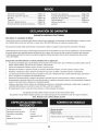
EngineOil Type:
SAE5W-30
EngineOil Capacity:
FuelCapacity:
20 ounces
3 Quarts
SparkPlug:
SparkPlug Gap:
Champion®RC12YC
.030"
Model Number.................................................................
Serial Number .................................................................
Dateof Purchase.............................................................
Recordthe modelnumber,serialnumber
and dateof purchaseabove
© Sears Brands,LLC
2
This machinewas builtto be operatedaccordingto the safe operation practicesin this manual.As with any type of powerequipment,
carelessnessor error on the partof the operatorcan result in serious
injury.This machineis capableof amputatingfingers,hands,toes
and feet and throwingdebris. Failureto observethe followingsafety
instructionscould resultin seriousinjuryor death.
This symbolpointsout importantsafetyinstructionswhich,if not
followed,couldendangerthepersonalsafetyand/orpropertyof
yourselfand others. Readand followall instructionsin this manual
beforeattemptingto operatethis machine.Failureto complywith
these instructionsmay resultin personalinjury.Whenyou seethis
symbol,HEEDITS WARNING!
CALIFORNIA
PROPOSiTiON
65
Your Responsibility--Restrict the useof this powermachineto
personswho read,understandand follow thewarningsand instructions in this manualand on the machine,
EngineExhaust,someof its constituents,and certainvehicle
componentscontainor emit chemicalsknownto Stateof California
to cause cancerand birthdefects or otherreproductiveharm,
SAVE THESE INSTRUCTIONS!
TRAiNiNG
PREPARATION
•
Thoroughlyinspectthearea wherethe equipmentisto be used.
Removeall doormats,newspapers,sleds,boards,wires and other
foreignobjects,whichcouldbe trippedoveror thrownby the auger/
impeller.
•
Alwayswear safetyglassesor eyeshieldsduringoperationand
while performingan adjustmentor repairto protectyoureyes.
Thrownobjectswhich ricochetcancause seriousinjuryto the
eyes.
Donot operatewithoutwearingadequatewinteroutergarments.
Donot wearjewelry,long scarvesor otherlooseclothing,which
could becomeentangledin movingparts.Wearfootwearwhich
will improvefooting on slipperysurfaces.
Usea groundedthree-wireextensioncordand receptaclefor all
machineswith electricstartengines.
•
•
Read,understand,and followall instructions
on the machineand
in themanual(s)beforeattemptingto assembleand operate.
Keepthis manualin a safe placefor futureand regularreference
and for orderingreplacementparts.
Readthe Operator'sManualand followall warningsand safety
instructions.Failureto do so can resultin seriousinjuryto the
operatorand/orbystanders.Forquestionscall, 1-800-659-5917.
Be familiarwith all controlsand their properoperation.Knowhow
to stop the machineand disengagethemquickly.
Neverallowchildrenunder 14 yearsof age to operatethis
machine.Children14and over shouldreadand understandthe
instructionsand safe operationpracticesin this manualand on
the machineand be trainedand supervisedby an adult.
Neverallowadultsto operatethis machinewithoutproper
instruction.
•
Adjust collectorhousingheightto cleargravelor crushedrock
surfaces.
Thrownobjectscan causeseriouspersonalinjury. Planyour
snow-throwingpatternto avoiddischargeof materialtoward
roads,bystandersand the like.
Disengageall controlleversbeforestartingthe engine.
•
Keepbystanders,pets and childrenat least75 feet from the
machinewhile it is in operation.Stopmachineif anyoneenters
the area.
•
Exercisecautionto avoidslippingor falling,especiallywhen
operatingin reverse.
3
Neverattemptto make anyadjustmentswhileengineis running,
exceptwherespecificallyrecommendedin the operator'smanual.
Letengineand machineadjustto outdoortemperaturebefore
startingto clearsnow.
Safe Handling of Gasoline
Toavoidpersonalinjuryor propertydamageuseextremecare in
handlinggasoline.Gasolineis extremelyflammableand the vaporsare
explosive.Seriouspersonalinjurycan occurwhengasolineis spilled
on yourselfor yourclotheswhichcan ignite.Washyour skin and
changeclothesimmediately.
•
•
•
Neverremovegas capor add fuel whilethe engineis hot
or running.
•
•
Allowengine to coolat leasttwo minutesbeforerefueling.
Neveroverfill fueltank. Filltank to no morethan1/2inch
belowbottomof filler neckto providespacefor fuel
expansion.
Replacegasolinecap and tightensecurely.
•
•
•
•
•
•
•
•
Useonly an approvedgasolinecontainer.
Extinguishall cigarettes,cigars,pipesand other sources
of ignition.
Neverfuelmachineindoors.
•
•
•
•
Donot overloadmachinecapacityby attemptingto clearsnowat
too fastof a rate.
•
Neveroperatethis machinewithoutgoodvisibility or light. Always
be sureof yourfootingand keepa firm hold on the handles.Walk,
neverrun.
•
Disengagepowerto theauger/impellerwhentransportingor not
in use.
•
Neveroperatemachineat high transportspeedson slippery
surfaces.Lookdownand behindand usecare whenbackingup.
If the machineshouldstart to vibrateabnormally,stop the engine,
disconnectthe spark plugwire and groundit againstthe engine.
Inspectthoroughlyfor damage.Repairanydamagebefore
startingand operating.
•
startingthe engine.
Neverstorethe machineor fuel containerinsidewhere
thereis an open flame,sparkor pilotlight (e.g.furnace,
waterheater,space heater,clothesdryer etc.).
•
Allowmachineto cool at least5 minutesbeforestoring.
Neverfill containersinsidea vehicleor on a truckor trailer
bed with a plasticliner.Alwaysplacecontainerson the
groundawayfromyourvehicle beforefilling.
•
•
•
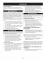
OPERATION
•
•
•
•
•
•
•
Do not puthandsor feet near rotatingparts,in the auger/impeller
housingor chuteassembly.Contactwith the rotatingpartscan
amputatehandsand feet.
•
Theauger/impellercontrol leveris a safetydevice.Neverbypass
its operation.Doingso makesthe machineunsafeand may cause
personalinjury.
Thecontrol leversmustoperateeasilyin bothdirectionsand
automaticallyreturnto the disengagedpositionwhenreleased.
Neveroperatewith a missingor damagedchuteassembly.Keep
all safetydevicesin placeand working.
Neverrun an engine indoorsor in a poorlyventilatedarea. Engine
exhaustcontainscarbonmonoxide,an odorlessand deadlygas.
Do notoperatemachinewhileunder the influenceof alcoholor
drugs.
Mufflerand engine becomehotand can causea burn.Do not
touch.Keepchildrenaway.
4
Planyoursnow-throwingpatternto avoiddischargetowards
windows,walls,cars etc. Thus,avoidingpossibleproperty
damageor personalinjurycausedby a ricochet.
Neverdirect dischargeat children,bystandersand petsor allow
anyonein front of the machine.
•
If gasolineis spilled,wipeit off the engineand equipment.
Movemachineto anotherarea.Wait5 minutesbefore
If possible,removegas-poweredequipmentfrom thetruck
or trailerand refuelit on the ground.If this is not possible,
then refuelsuch equipmenton a trailerwith a portable
container,ratherthan from a gasolinedispensernozzle.
Keepthe nozzlein contactwith the rimof the fueltank or
containeropeningat all timesuntil fuelingis complete.Do
notuse a nozzlelock-opendevice.
Exerciseextremecautionwhenoperatingon or crossinggravel
surfaces.Stay alertfor hidden hazardsor traffic.
Exercisecautionwhenchangingdirectionand whileoperatingon
slopes.
Disengageall controlleversand stop enginebeforeyouleave
the operatingposition(behindthe handles).Wait untilthe auger/
impellercomesto a completestop beforeuncloggingthechute
assembly,makingany adjustments,or inspections.
Neverput yourhand in the dischargeor collectoropenings.
Alwaysusethe clean-outtool providedto unclogthedischarge
opening.Donot unclogchuteassemblywhileengine is running.
Shutoff engineand remainbehindhandlesuntilall movingparts
havestoppedbeforeunclogging.
Useonly attachmentsand accessoriesapprovedby the manufacturer (e.g.wheelweights,tire chains,cabsetc.).
Whenstartingengine,pull cord slowlyuntilresistanceis felt, then
pull rapidly.Rapidretractionof startercord(kickback)will pull
hand and armtowardenginefasterthan youcan let go. Broken
bones,fractures,bruisesor sprainscould result.
If situationsoccur whichare notcoveredin this manual,use care
and good judgment.ContactCustomerSupportfor assistance
and the nameof your nearestservicingdealer.
MAINTENANCE
& STORAGE
•
Nevertamperwith safetydevices.Checktheirproperoperation
regularly.Referto the maintenanceand adjustmentsectionsof
this manual.
•
Beforecleaning,repairing,or inspectingmachinedisengageall
controlleversand stop the engine.Wait untilthe auger/impeller
cometo a completestop.Disconnectthe sparkplug wireand
groundagainsttheengine to preventunintendedstarting.
Checkboltsand screwsfor propertightnessat frequentintervals
to keepthe machinein safe workingcondition.Also, visually
inspectmachinefor anydamage.
Do notchangetheengine governorsettingor over-speedthe
engine.Thegovernorcontrolsthe maximumsafeoperatingspeed
of the engine.
Snowthrowershaveplatesand skid shoesare subjectto wear
and damage.Foryoursafetyprotection,frequentlycheckall
componentsand replacewith originalequipmentmanufacturer's
(OEM)parts only."Useof parts whichdo not meetthe original
equipmentspecificationsmay leadto improperperformanceand
compromisesafety!"
Checkcontrolleversperiodicallyto verifythey engageand disengage properlyand adjust,if necessary.Referto the adjustment
sectioninthis operator'smanualfor instructions.
•
Maintainor replacesafetyand instructionlabels,as necessary.
Observeproperdisposallawsand regulationsfor gas, oil,etc. to
protectthe environment.
Priorto storing,run machinea few minutestoclear snowfrom
machineand preventfreezeup of auger/impeller.
Neverstorethe machineor fuel containerinsidewherethereisan
open flame,spark or pilot lightsuch as a waterheater,furnace,
clothesdryer etc.
Alwaysreferto the operator'smanualfor properinstructions
on
off-seasonstorage.
Checkfuelline,tank, cap,and fittings frequentlyfor cracksor
leaks.Replaceif necessary.
Do notcrank enginewith spark plug removed.
Accordingto the ConsumerProductsSafetyCommission(CPSC)
and the U.S.EnvironmentalProtectionAgency(EPA),this product
hasan AverageUsefulLifeof seven(7) years,or 60 hoursof
operation.At the end of theAverageUsefulLifehavethe machine
inspectedannuallybyan authorizedservicedealer to ensurethat
all mechanicaland safetysystemsare workingproperlyand not
wornexcessively.Failureto do so can resultin accidents,injuries
or death.
DO NOT MODIFY
ENGINE
Toavoidseriousinjuryor death,do not modifyengine in any way.
Tamperingwith the governorsettingcanlead to a runawayengineand
cause it to operateat unsafespeeds.Nevertamperwithfactory setting
of engine governor.
NOTICE
REGARDING
EMISSIONS
Engineswhich are certifiedtocomplywith Californiaand federal
EPAemissionregulationsfor SORE(SmallOff RoadEquipment)are
certifiedto operateon regularunleadedgasoline,and mayinclude
the followingemissioncontrol systems:EngineModification(EM),
OxidizingCatalyst(OC), SecondaryAir Injection(SAI)and ThreeWay
Catalyst(TWO)if so equipped.
SPARK
ARRESTOR
This machineisequippedwith an internalcombustionengineand
shouldnotbe usedon or nearany unimprovedforest-covered,
brush-coveredor grass-coveredland unlessthe engine'sexhaust
systemisequippedwith a sparkarrestermeetingapplicablelocalor
statelaws (if any)
If a sparkattester is used, it shouldbe maintainedin effectiveworking
order by theoperator.Inthe State of Californiathe aboveis required
bylaw (Section4442 of the CaliforniaPublicResourcesCode). Other
statesmayhavesimilarlaws. Federallawsapplyon federallands.
A spark arresterfor the muffleris availablethroughyournearestSears
Partsand RepairServiceCenter.
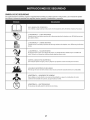
SAFETY
SYMBOLS
This pagedepictsand describessafetysymbolsthat mayappear on this product. Read,understand,and followall instructionson the machine
beforeattemptingto assembleand operate.
i
READ THE OPERATOR'S MANUAL(S)
Read, understand,
i
and follow
all instructions
in the manual(s) before
attempting
to assemble
and
operate
WARNING--
ROTATING BLADES
Keep hands out of inlet and discharge openings
inside
WARNING--
WARNING--
with the rotating
WARNING--THROWN
This machine
blades
while
machine
is running.
There are rotating
blades
parts, in the auger/impeller
parts can amputate
housing
or chute assembly.
hands and feet.
OBJECTS
can cause serious personal
injury.
IS FLAMMABLE
Allow the engine to cool at least two minutes
before refueling.
CARBON MONOXIDE
Never run an engine indoors
WARNING--
There are rotating
may pick up and throw and objects which
WARNING--GASOLINE
monoxide,
is running.
ROTATING AUGER
Do not put hands or feet near rotating
WARNING--
machine
ROTATING BLADES
Keep hands out of inlet and discharge openings
inside
Contact
while
or in a poorly ventilated
an odorless and deadly gas.
ELECTRICAL SHOCK
Do not use the engine's
electric starter in the rain
6
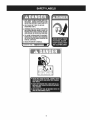
area. Engine exhaust contains carbon
1.KEEPAWAYFROMROTATING
iMPELLER
ANDAUGER,CONTACT
WiTHiMPELLER
OR
AUGERCANAMPUTATE
HANDSANDFEET.
2. USECLEAN-OUT
TOOLTOUNCLOG
DISCHARGE
CHUTE.
3.DISENGAGE
CLUTCHLEVERS,
STOPENGINE,
AND REMAINBEHINDHANDLESUNTILALL
MOVING PARTSHAVE STOPPEDBEFORE
UNCLOGGING OR SERViCiNGMACHINE.
TO AVOIDTHROWN OBJECTSiNJURiES,
NEVERDIRECTDISCHARGE
ATBYSTANDERS.
USEEXTRACAUTIONWHEN OPERATING
ON
GRAVEL SURFACES.
5.BEAD OPERATOR'S MANUAL.
CLEAN-OUT TOOL
7
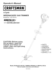
NOTE:Referencesto rightor left sideof the snowthrowerare
determinedfrom behindthe unit in the operatingposition(standing
directlybehindthe snow thrower,facingthe handlepanel).
REMOVING
1.
2.
3.
FROM CARTON
Cut the cornersof thecarton and lay the sidesflat on the ground.
Removeand discard all packinginserts.
Movethe snowthrowerout of thecarton.
Makecertainthe carton has beencompletelyemptiedbefore
discardingit.
LOOSE
PARTS
Tworeplacementaugershearpinsare includedwith this manual.Refer
to ReplacingShear Pinsin the Operationsectionfor moreinformation
regardingshearpin replacement.
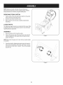
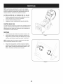
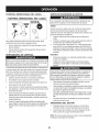
ASSEMBLY
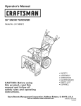
1.
2.
Placethe shiftleverin the Forward-6position.
Observethe lowerreararea of the snowthrowerto be sure both
cablesare alignedwith rollerguidesbeforepivotingthe handle
upward.See Figure1.
Figure1
NOTE:Makecertainthe upperends of eachcableare seatedproperly
in its bracket.
.
f
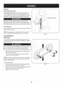
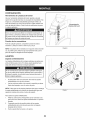
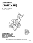
Securethehandle bytighteningthe plasticwing knoblocatedon
boththe left and rightsides of the handle.See Figure2. Remove
and discardany rubberbands,if present.They are for packaging
purposesonly.
!
/
/
/
Figure2
8
.
5.
Positionthechute assemblyoverthe base.See Figure3.
Closethe flangekeepersto securethechute assemblyto the
chute base.See Figure4. The flangekeeperswill click intoplace
whenproperlysecure.
NOTE:If the flangekeeperswill noteasily clickinto place,usethe
palmof yourhand to applyswift,firm pressureto the backof each.
.
a.
b.
Removetheflat washerand hairpinclip from the end of the
chutedirectionalcontrol.
Insertthe end of the chutedirectionalcontrolinto the lower
bracketand securewith the flat washerand hairpinclipjust
removed.See Figure5. If necessary,the lowerbracketcan
be adjusted.Referto ChuteBracketAdjustmentin the
Service& Maintenancesection.
Figure4
f
F
\
Figure5
Figure3
9
J
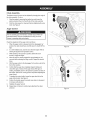
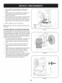
SET-UP
Chute
Clean-Out
Tool
A chute clean-out tool is fastenedto the top of the augerhousing
with a mountingclip. See Figure6. The tool is designedto cleara
chuteassemblyof ice and snow.This item is fastenedwith a cabletie
at the factory.Cut thecable tie beforeoperatingthe snowthrower.
ChuteClean-outTool
loft _1
.allmovingpartshave
stoppedbeforeusingthe clean-outtool to clearthe chuteassembly.
Tire Pressure
Beforeoperating,checktire pressureand reducepressurein bothtires
to between15 psiand 20 psi.
NOTE:If thetire pressureis notequal in bothtires,the unit maynot
travelin a straightpathand the shaveplatemay wearunevenly.
Figure6
ADJUSTMENTS
Skid Shoes
f
The snowthrowerskid shoesare adjustedupwardat thefactory for
shippingpurposes.Adjustthemdownward,if desired,priorto operating the snowthrower.
/
It is not recommendedthat youoperatethis snowthroweron gravel
as it can easilypick up and throwloosegravel,causingpersonal
njuryor damageto the snowthrowerand surroundng property.
•
•
Forclose snow removalon a smoothsurface,raiseskid shoes
higheron the auger housing.
Use a middleor lowerpositionwhenthearea to be clearedis
uneven,such as a graveldriveway
NOTE:If youchooseto operatethe snowthroweron a gravelsurface,
keepthe skid shoesin positionfor maximumclearancebetweenthe
groundand the shaveplate.
Toadjustthe skid shoes:
1. Loosenthe four hexnuts (two on each side)and carriagebolts.
Moveskid shoesto desiredposition. See Figure7.
2. Makecertainthe entirebottomsurfaceof skid shoeis againstthe
groundto avoidunevenwearon the skid shoes.
3.
Figure7
Retightennuts and boltssecurely.
10
Chute
Assembly
Thedistancesnowis throwncan be adjustedby changingthe angle of
the chuteassembly.Todo so:
1.
2.
Stopthe engineby removingthe ignitionkeyand loosenthe
plasticwingknobfoundon the left sideof the chuteassembly.
Pivotthe chute upwardor downwardbeforeretighteningthewing
knob.See Figure8.
Auger Control
Priorto operatingyour snowthrower,carefullyreadand followall
instructionsbelow. Performall adjustmentsto verifyyour snow
throweris operatingsafelyand properly.
Checktheadjustmentof the augercontrolas follows:
1.
2.
3.
4.
Whentheauger controlis releasedand in the disengaged"up"
position,the cableshouldhavevery little slack. It shouldNOTbe
tight.
In a well-ventilatedarea,start the snowthrowerengine.Referto
Startingthe Enginein the Operationsection.
Whilestandingin the operator'sposition(behindthe snow
thrower),engagethe auger.
Allowtheauger to remainengagedfor approximatelyten (10)
secondsbeforereleasingthe augercontrol.Repeatthis several
times.
5.
With theauger controlin thedisengaged"up" position,walkto the
front of the machine.
6.
Confirmthat the augerhas completelystoppedrotatingand
showsNOsigns of motion.If the augershowsANYsignsof
rotating,immediatelyreturnto the operator'spositionand shutoff
the engine.Waitfor ALL movingparts to stop beforeadjustingthe
augercontrol.
Toreadjustthecontrolcable, loosentheupper hexbolt on the
augercablebracket.See Figure9.
7.
8.
9.
Figure8
Positionthe bracketupwardto providemoreslack(or downward
to increasecabletension).
Retightenthe upperhex bolt.
10. Repeatsteps2-6 aboveto verifyproperadjustmenthasbeen
achieved.
Figure9
11
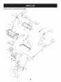
Auger Control
Gas Cap
ChuteAssembly
\
Chute Directional
Control
\
Clean Out
Tool
Recoil Starter
Handle
'\
\
Electric Start
Button
Augers
_
Skid Shoe
Outlet
J
Figure10
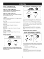
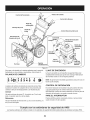
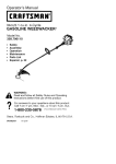
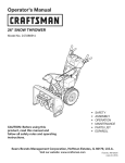
iGNiTiON
Nowthat youhaveset up yoursnowthrower,it'simportantto become
acquaintedwith its controlsand features.Referto Figure10.
SHIFT
The ignitionkeyisa safetydevice.It mustbe fully insertedin orderfor
the engineto start. Removethe ignitionkeywhenthe snowthroweris
not in use.
LEVER
1
2345
KEY
'
NOTE: Donot turnthe ignitionkey inan attemptto startthe engine.
Doingso may causeitto break.
6
CHOKE
CONTROL
The chokecontrolisfoundon the rearof the engineand isactivated
by turningthe rotarychoke knobto the CHOKEposition.Activating
the chokecontrolclosesthe choke plateon thecarburetorand aids in
startingthe engine.
The shiftleverislocatedon the dash panel.Placethe shift leverinto
anyof eight positionsto controlthe directionof travel and ground
speed.
Forward
Yoursnowthrowerhas six forward(F) speeds.Positionone (1)is the
slowestand positionsix (6) isthe fastest.
Reverse
STOP SWITCH
Pressintothe ON positionwhen startingthe engineand will shut off
the enginewhenmovedintotheOFF position.
Yoursnowthrowerhastwo reverse(R) speeds.One (1) isthe slower
and two (2) isthe faster.
Meets ANSi Safety Standards
CraftsmanSnowThrowersconformto the safetystandardof the AmericanNationalStandardsInstitute(ANSI).
12
RECOIL STARTER HANDLE
DRIVE CONTROL/AUGER
This handleis usedto manuallystartthe engine.
ELECTRIC
STARTER
CONTROL
LOCK
f
BUTTON
Pressingthe electricstarterbuttonengagesthe engine'selectric
starterwhenpluggedintoa 120Vpowersource,
ELECTRIC
STARTER
OUTLET
Requiresthe useof a three-prongoutdoorextensioncord(included)
and a 120Vpowersource/walloutlet.
PRIMER
Depressingthe primerforcesfuel directlyintothe engine'scarburetor
to aid in cold-weatherstarting,
The drivecontrolis locatedon the righthandle.Squeezethe control
grip againstthe handleto engagethe wheeldrive. Releaseto stop.
The drivecontrolalso lockstheauger controlso youcan operate
the chute directionalcontrolwithoutinterruptingthe snowthrowing
process,if the augercontrolisengagedsimultaneouslywith the drive
control,the operatorcan releasethe augercontrol (on the lefthandle)
and the augerswill remainengaged.Releaseboth controlsto stop the
augersand wheeldrive.
OiL FILL
Engineoil levelcan be checkedand oil addedthroughtheoil fill.
GAS CAP
Unthreadthe gascap to add gasolineto the fuel tank.
AUGERS
Whenengaged,the augersrotateand drawsnow intothe auger
housing.
NOTE:Alwaysreleasethedrivecontrol beforechangingspeeds.
Failureto do so will result in increasedwearon yourmachine'sdrive
system.
CHUTE
CHUTE
ASSEMBLY
Snowdrawninto theauger housingis dischargedout the chute
assembly.
AUGER
DIRECTIONAL
CONTROL
f
-\
CHUTE
CONTROL
DiRECTiONAL
DISCHARGE
LEFT
DISCHARGE
CONTROL
ADJUSTABLE
CHUTETILT
\
The chutedirectionalcontrol is locatedon left sideof the snowthrower.
Tochangethe directionin which snowis thrown,turnchutedirectional
controlas follows:
*
*
Theaugercontrol is locatedon the left handle.Squeezethecontrol
grip againstthe handleto engagetheaugersand start snowthrowing
action.Releaseto stop.
Crankclockwiseto dischargeto the left.
Crankcounterclockwiseto dischargeto the right.
SKiD SHOES
Positionthe skid shoesbasedon surfaceconditions.Adjustupward
for hard-packedsnow.Adjustdownwardwhenoperatingon gravelor
crushedrock surfaces.
13
CLEAN-OUT TOOL
Useextremecarewhen handlinggasoline.Gasolineis extremely
flammableand thevaporsare explosive.Never fuelthe machine
indoorsor whilethe engine is hotor running.Extinguishcigarettes,
cigars,pipesand othersourcesof ignition.
Neveruseyour handsto cleara cloggedchuteassembly.Shut
off engineand remainbehind handlesuntilall movingparts have
stoppedbeforeusingthe clean-outtool to clearthe chute assembly.
Alwaysfill the fuel tank outdoorsand usea funnelor spoutto
preventspilling.
Thechute clean-outtool is convenientlyfastenedto the rear of the
augerhousingwith a mountingclip. Shouldsnowand ice become
lodgedin thechute assemblyduringoperation,proceedas followsto
safelycleanthechute assemblyand chute opening:
1. Releaseboththe AugerControland the DriveControl.
2.
3.
4.
5.
6.
•
Fillfuel tank with clean,fresh,unleadedgasolinewith a minimum
of 85 octane.Freshfuel preventsgumfrom formingin the fuel
systemor on essentialcarburetorparts.Purchasefuelin a
quantitythat can be usedwithin30 days.
Neverfill the fuel tank completely.Fillthe tank to within 1-1/2"
from the top to providespacefor expansionof fuel.
Makesureto wipeoff anyspilledfuel beforestartingthe engine.
•
Stopthe engineby removingthe ignitionkey.
Removethe clean-outtoolfrom the clip whichsecuresit to the
•
rear of the augerhousing.
Use the shovel-shapedend of theclean-outtool to dislodgeand
scoopany snowand icewhich hasformedin and near thechute
assembly.
STARTING
Refastenthe clean-outtool to the mountingclip on the rear of
theauger housing,reinsertthe ignitionkey and startthe snow
thrower'sengine.
Whilestandingin the operator'sposition(behindthesnow
thrower),engagethe auger controlfora few secondsto clear any
remainingsnowand ice from thechute assembly.
1.
Makecertainboththe augercontrol and drivecontrolare in the
disengaged(released)position.
2.
Insertignitionkey into slot.Makesure it snapsinto place.Do not
attemptto turn the key.
NOTE: Theenginecannot startwithoutthe keyis fully insertedintothe
ignitionswitch.
Electric
BEFORE
STARTING
ENGINE
Oil
The unitwas shippedwith oil in the engine.Checkoil levelbeforeeach
operationto ensureadequateoil in the engine.Forfurther instructions,
referto the stepson page 16.
Removethe dipstickfrom the oil fill.
Checkand makesurethat the levelof oil is up to the FULLmark
on the dipstick.
3.
If the oil levelis not up to FULL,pour fresh motoroil (5W-30,with
a minimumclassificationof SF/SG/SH/SJ)slowlythroughthe
opening.Replaceoil fill dipstickand checkoil levelagain.
The optionalelectricstarteris equippedwith a groundedthree-wire
powercordand plug,and is designedto operateon 120volt AC
householdcurrent.It mustbe usedwith a properlygroundedthreeprong receptacleat all timesto avoidthe possibilityof electricshock.
Followall instructionscarefullyprior to operatingtheelectricstarter.
DONOTuse electricstarterin the rain.
If you havea groundedthree-prongreceptacle,proceedas follows:
1.
2.
•
Storegasolinein a clean, approvedcontainerand keepthecap in
placeon the container.
Makesurethat the containerfrom which youpour the gasolineis
cleanand freefrom rust or otherforeignparticles.
14
Plugthe extensioncord intothe outlet locatedon the engine's
surface.Plug the otherend of extensioncord intoa three-prong
120-volt,grounded,AC outlet in a well-ventilatedarea.
Rotatechokecontrolto CHOKE I Jl position.
3.
If it is 15°For higherpushprimertwo times,if below15°F,push
primerfourtimes.
4.
PushStopswitchto ON position.
Gasoline
•
Starter
Determinethat yourhome'swiringis a three-wiregroundedsystem.
Ask a licensedelectricianif you are notcertain.
Read,understand,and followall instructionsand warningson the
machineand in this manualbeforeoperating.
1.
2.
THE ENGINE
5.
Pushstarterbuttonto start engine.
NOTE:NEVERrepositiontheshift lever(changespeedsor direction
of travel)withoutfirst releasingthe drivecontrol and bringingthe snow
throwerto a completestop.Doingsowill resultin prematurewearto
the snow thrower'sdrivesystem.
To prolongstarterlife, useshort startingcycles(5 secondsmaximum
then wait one minute).
TO ENGAGE
6.
Oncethe enginestarts,releasestarterbutton.
7.
Allowtheengine to warmup severalminutes,adjustingchoke
towardRUNposition.Wait untilengineruns smoothlybeforeeach
chokeadjustment.
Whendisconnectingthe extensioncord, alwaysunplugthe end
at the three-prongwalloutlet beforeunpluggingthe oppositeend
from the snowthrower.
8.
Recoil
1.
2.
3.
4.
5.
6.
1.
Starter
Rotatechoke controlto CHOKE IJl position.
Depressprimer.If it is 15°For higherpushprimertwo times,if
below15°F,pushprimerfourtimes.
PushStopswitchto ONposition.
AUGERS
Toengagethe augersand startthrowingsnow,squeezethe
auger controlagainstthe left handle.Releaseto stop theaugers.
REPLACING
SHEAR
PINS
The augersare securedto the spiralshaftwith four shearpinsand
bow-tieclips. If the augershouldstrikea foreignobject or icejam,
the snow throweris designedsothat the shearpins mayshear.If the
augerswill notturn, checkto see if the pins havesheared.See Figure
11.
NEVERreplacethe augershearpinswith anythingotherthan Sears
SKU#88389/OEM PartNo. 738-04124Areplacementshearpins.
Anydamageto theauger gearboxor other componentsas a resultof
failingto do sowill NOTbe coveredbyyour snowthrower'swarranty.
Graspthe recoilstarterhandleand slowlypull the ropeout. At
the pointwhereit becomesslightlyharderto pull the rope,slowly
allowthe ropeto recoil.
Pull the starterhandlewith a firm, rapid stroke.Donot release
the handleand allowit to snap back.Keepa firm hold on the
starterhandleand allowit to slowlyrecoil.
Allowtheengine to warmup severalminutes,adjustingchoke
towardRUNposition.Wait untilengineruns smoothlybeforeeach
chokeadjustment.
Alwaysturn off thesnow thrower'sengineand removethe key priorto
replacingshearpins.
f
To avoidunsupervisedengineoperation,neverleavethe machine
unattendedwith the engine running.Turnthe engineoff after useand
removeignitionkey.
STOPPING
THE ENGINE
After youare finishedsnow-throwing,run enginefor a few minutes
beforestoppingto help dry off any moistureon the engine.
1. PushStopswitchto OFFposition.
2.
3.
Removetheignitionkey and store in a safe place.
Wipeall snowand moisturefrom thearea aroundthe engineas
wellas the area in and aroundthe drivecontroland auger control.
Also,engageand releasebothcontrolsseveraltimes.
TO ENGAGE
1.
DRIVE
Figure11
Moveshift leverintoone of the six forward(F) positionsor two
reverse(R) positions.Selecta speedappropriatefor the snow
conditionsand a paceyou'recomfortablewith.
NOTE: Whenselectinga DriveSpeed,usethe slowerspeedsuntil
youare comfortableand familiarwith the operationof the snow
thrower.
2.
Squeezethedrive controlagainstthe handleand thesnow
throwerwill move.Releaseit and drivemotionwill stop.
15
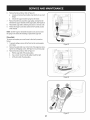
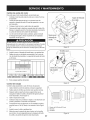
MAINTENANCE
Beforeperforminganytypeofmaintenance/service,
disengageall
controlsand stoptheengine.Waituntilall movingpartshavecometo
a completestop.Disconnectsparkplugwireandgrounditagainstthe
enginetopreventunintendedstarting.Alwayswearsafetyglassesduring
operationor whileperforminganyadjustmentsor repairs.
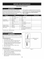
SCHEDULE
Followthe maintenanceschedulegiven below.This chart describes
serviceguidelinesonly. Usethe ServiceLog columnto keeptrackof
completedmaintenancetasks.To locate the nearest Sears Service
Centeror to scheduleservice,simplycontactSearsat
1-800-4-MY-HOME®.
=
EachUse
=
1.
Check
Unitand engine.
2.
3.
Tightenor replace
Clean
1.
Engineoil
1.
Change
1.
Engineoi11-
1.
Change
2.
3.
Controllinkagesand pivots
Wheels
4.
Gearshaft and Augershaft
2.
3.
4.
Lubewith lightoil
Lubewith multipurposeautogrease
Lubewith lightoil
Annuallyor 50 hours
1.
Engineoil
1.
Change
Annuallyor 100 hours
1.
Sparkplug
1.
Check/Change
BeforeStorage
1.
Fuelsystem
1.
Runengineuntilit stopsfrom lackof
fuel or add a gasolineadditiveto the
gas in thetank.
1.
2.
Engineoil level
Looseor missinghardware
3.
1st5 to 8 hours
Annuallyor 25 hours
Underheavyload or inhigh temperatures
ENGINE
f
MAINTENANCE
..J
,,.J
Beforelubricating,repairing,or inspecting,disengageall controls
Iand stop engine.Wait untilall movingpartshavecometo a complete
[stop.
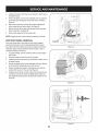
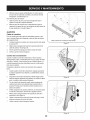
Checking
1.
2.
3.
Be sureengine is uprightand level.
Unscrewoil fill capfrom oil fillertubeand wipe dipstickclean.
Screwoil fill capback intooil fillertube. Tightensecurely.
4.
5.
Unscrewand removeoil fill cap from oil filler tube. Noteoil level.
If oil readingon dipstick isbelow"ADD"mark,slowlyadd oil to
reach"FULL"level.See Figure12.
Screwoil fill capback intooil fillertube. Tightensecurely.
6.
Wipeawayany spilledoil.
Changing
U.,
Engine Oil
a
a
Engine Oil
J
Toavoidenginedamage,it is importantto:
•
Checkoil levelbeforeeachuseand every eightoperatinghours.
•
1.
2.
Maintain oil level
at FULL
Figure12
Changeoil afterfirst 5 to 8 operatinghoursand every 50 operating hoursor oncea seasonthereafter.
Placeengineleveland removesafety key.
Disconnectspark plug wireand keepit awayfrom sparkplug
(Referto next section). If connected,disconnectextensioncord
from powersource.
16
3. Withengine
OFFbutstillwarm,
remove
oildrainpluganddrain
oil
intoanappropriate
receptacle.
SeeFigure
13.
0il FIll
Used
oilisahazardous
waste
product.
Dispose
ofused
oilproperly.
IDonotdiscard
withhousehold
waste.
Check
withyourlocalauthoriIties or SearsServiceCenterfor safedisposal/recyclingfacilities.
4.
Reinstalloil drain plug and tightensecurely.
5.
Refillthe enginewith recommendedoil. See RecommendedOil
Usagechart.The engine'soil capacityis 20 ounces.
Recommended Oil Usage
Oil Drain
Figure13
g
6.
Screws
Wipeawayany spilledoil.
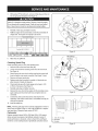
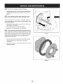
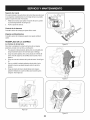
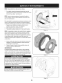
Checking
Spark Plug
Checksparkplug yearlyor every 100operatinghours.
1.
2.
Removechokecontrolknoband safety key.
Loosenand removethe mountingscrewsfromthe snow hood.
See Figure14.
3.
Slowlyremovethe snow hood,makingsurethat the primerbulb
hoseand ignitionwireremainconnected.See Figure14 inset.
Removeand inspectspark plug.
Replacesparkplug if porcelainiscrackedor if electrodesare
pitted,burnedor fouledwith deposits.
4.
5.
6.
7.
Checkelectrodegap with a feelergaugeand set gap to .030
(0.76ram)if necessary.See Figure15.
Reinstallspark plugand tightensecurely.
8.
Remountthe snowhoodto the enginewith themountingscrews,
againmakingsurethe primerbulb hoseand ignitionwireare
connected.
9.
Connectthe chokecontrolknobto thechoke shafton the
carburetor.If the chokecontrol knobisnot installed
correctly,the
chokewill notoperate.
Figure14
,,!
10. Installthe safetykey.
NOTE:A resistorsparkplug mustbe usedfor replacement.Contacta
SearsPartsand RepairCenteror 1-800-4-MY-HOME®
for a replacement sparkplug,Champion®partnumberRC12YC.
Carburetor
Enginesoperatedat about3000 to 5000 feet (900 to 1500meters)
abovesealevelmay requirea high altitudecarburetormainjet. If
erraticperformanceis observed,contacta SearsPartsand Repair
Centerfor costto install/purchase
a high altitudecarburetormainjet.
1..030 (.76 mm) Gap
2. Electrodes
_.
Porcelain
Figure15
17
Engine Speed
Toavoidserious injuryor death, DONOTmodifyenginein any
way.Tamperingwith the governorsettingcan causethe engineand
equipmentto operateat unsafespeeds.NEVERtamperwith factory
settingof enginegovernor.Runningthe enginefasterthan the speed
set at thefactory is dangerous.
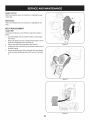
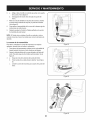
LUBRICATION
Gear Shaft
Thegear (hex)shaft shouldbe lubricatedat least oncea seasonor
afterevery 25 hoursof operation.
1.
2.
3.
4.
Topreventspillage,removeall fuel fromtank by runningengine
until it stops.
Carefullypivotthe snowthrowerup and forwardso that itrestson
theauger housing.
Removethe lowerframecover fromthe undersideof the snow
throwerby removingthe four self-tappingscrewswhichsecureit.
J
Figure16
Applya lightcoatingof engineoil (or 3-in-1oil) to the hexshaft.
See Figure16.
NOTE:Whenlubricatingthe hexshaft, be carefulnotto get any oil on
thealuminumdriveplateor rubberfrictionwheel. Doingsowill hinder
the snowthrower'sdrive system.Wipeoff anyexcessor spilledoil.
Wheels
At least oncea season,removebothwheels.Cleanand coat theaxles
with a multipurposeautomotivegreasebeforereinstallingwheels.
Chute
Directional
Control
Oncea season,lubricatethe eye boltbushingand thespiralwith
3-in-1oil.
Auger Shaft
At least oncea season,removethe shearpinson augershaft. Spray
lubricantinsideshaft,and aroundthe spacersand flangebearings
foundat eitherend of the shaft. See Figure17.
SHAVE
,,.
Figure17
PLATE AND SKID SHOES
xX \
The shaveplateand skid shoeson the bottomof the snowthrowerare
subjectto wear.They shouldbe checkedperiodicallyand replaced
whennecessary.
To removeskid shoes:
1.
Removethe four carriagebolts,washers,and hex flangenuts
which securethem to the snowthrower.
2.
Reassemblenew skid shoeswith the fourcarriagebolts (two on
eachside), washers,and hex flangenuts.Referto Figure18.
To removeshaveplate:
1.
2.
\
Removethe carriageboltsand hexnuts whichattachit to the
snowthrowerhousing.
Reassemblenew shaveplate,makingsureheadsof carriage
bolts are to the insideof housing.Tightensecurely.Referto
Figure18.
\
\\
NOTE:Angers notshownfor clarity.
Figure18
18
ADJUSTMENTS
Shift Cable
If thefull rangeof speeds(forwardand reverse)cannotbe achieved,
referto the figureto the rightand adjustthe shift cableas follows:
1. Placethe shiftleverin thefastest (F6) forwardspeedposition.
2. Loosenthe hex nuton the shiftcable indexbracket.See Figure
19.
3.
4.
Pivotthe bracketdownwardto take up slack in the cable.
Retightenthehex nut.
Drive
Control
Whenthedrivecontrol is releasedand in thedisengaged"up"position,
the cableshouldhavevery little slack.It shouldNOTbe tight. Also,
if thereis excessiveslackin thedrive cableor if the unitexperiences
intermittentdrivewhileusing,the cable mayneed to be adjusted.
Checktheadjustmentof the drivecontrolas follows:
1.
2.
3.
With thedrivecontrol released,pushthe snowthrowergently
forward.The unitshouldroll freely.
Engagethe drivecontroland gently attemptto pushthe snow
throwerforward.Thewheelsshouldnotturn. The unitshouldnot
roll freely.
With thedrivecontrol released,movethe shift leverbackand
forth betweenthe R2positionand the F6 positionseveraltimes.
Thereshouldbe no resistancein the shiftlever.
f
4.
If anyof the abovetests failed,the drivecable is in needof adjustment.Proceedas follows:
5.
Loosenthe lowerhexbolt on the drivecable bracket.See Figure
20.
6.
Positionthe bracketupwardto providemoreslack(or downward
to increasecabletension).
Retightenthe lowerhex bolt.
7.
Chute
Figure19
Bracket
If the spiralat the bottomof the chutedirectionalcontrol is notfully
engagingwith the chuteassembly,the chute bracketcan be adjusted.
Todo so:
Figure20
f
1.
2.
Loosenthe two nuts which securethechute bracketand reposition it slightly.See Figure21.
Retightenthe nuts.
Figure21
19
Auger Control
Referto the Assemblysectionfor instructions
on adjustingtheauger
controlcable.
f
"_
Skid Shoes
Referto the Assemblysectionfor instructions
on adjustingthe skid
shoes.
BELT REPLACEMENT
Auger Belt
To removeand replaceyoursnow thrower'sauger belt, proceedas
follows:
1.
Topreventspillage,removeall fuel fromtank by runningengine
until itstops.
2.
Removethe plasticbelt coveron the front of the engineby removing the two self-tappingscrews.See Figure22.
Rollthe auger beltoff theengine pulley.See Figure23.
3.
4.
5.
Carefullypivotthe snowthrowerup and forwardso that itrestson
theauger housing.
Removethe frame coverfrom the undersideof the snow thrower
by removingfourself-tappingscrewswhich secureit. See Figure
24.
J
Figure22
f
Figure 23
f
//
J
Figure24
2O
6. Remove
thebeltasfollows.
Refer
toFigure
25.
a. Loosen
andremove
theshoulder
screw
which
actsasabelt
keeper.
b. Unhook
thesupport
bracket
spring
from
theframe.
7. Remove
thebeltfromaround
theauger
pulley,
andslipthebelt
between
thesupport
bracket
andtheauger
pulley.
SeeFigure
26.
8. Reassemble
auger
beltbyfollowing
instructions
inreverse
order.
9. Perform
theAuger
Control
testoutlined
intheAssembly
section
ofthismanual.
NOTE:
DoNOT
forget
toreinstall
theshoulder
screw
andreconnect
thespring
totheframe
afterinstalling
areplacement
auger
belt.
/"
Drive Belt
Toremoveand replaceyoursnow thrower'sdrivebelt, proceedas
follows:
1.
Topreventspillage,removeall fuel fromtank by runningengine
untilit stops.
2.
Removetheplasticbelt coveron the front of the engineby removing the two self-tappingscrews.See Figure22 on previouspage.
Removethebelt as follows.Referto Figure27.
3.
a.
b.
Rollthe auger beltoff theengine pulley.
Use a wrenchto pivotthe idlerpulleytowardthe right.
c.
Lift the drivebelt off enginepulley.
Figure25
Figure26
Figure27
21
}
4, Carefully
pivot
thesnow
thrower
upandforward
sothatitrests
on
theauger
housing.
5. Remove
theframe
cover
fromtheunderside
ofthesnow
thrower
byremoving
fourself-tapping
screws
which
secure
it.Refer
to
Figure
24,
6. Backoutthestopbolttoincrease
theclearance
between
the
friction
wheel
discandfriction
wheel,
SeeFigure
28,
7. Slipthedrive
beltoffthepulley
andbetween
friction
wheel
and
friction
wheel
disc,SeeFigure
28,
8, Remove
andreplace
beltinthereverse
order,
NOTE:
Engaging
thedrivecontrol
willeasereassembly
ofthebelt.
FRICTION
WHEEL
REMOVAL
Stop Bolt
If the snowthrowerfailsto drive with thedrivecontrol engaged,
and performingthe drivecontrolcableadjustmentfails to correct
the problem,the frictionwheelmayneed to be replaced.Followthe
instructionsbelow.Examinethe frictionwheelfor signsof wearor
crackingand replaceif necessary.
1. Topreventspillage,removeall fuel fromtank by runningengine
until it stops.
2.
3.
4.
5.
6.
Figure28
/
ii
Placethe shiftleverin third Forward(F3) position.
Carefullypivotthe snowthrowerup and forwardso that it restson
theauger housing.
Removethe frame coverfrom the undersideof the snow thrower
by removingfourself-tappingscrewswhich secureit.
Removethe right-handwheelby removingthe screwand bell
washerwhichsecureit to theaxle. See Figure29.
Carefullyremovethe hexnut and washerwhichsecuresthe hex
shaftto the snowthrowerframeand lightlytap the shaft'send
to dislodgethe ball bearingfrom the rightsideof theframe.See
Figure30.
J
Figure29
/
Figure30
22
NOTE:
Becareful
nottodamage
thethreads
ontheshaft,
7. Carefully
position
thehexshaft
downward
andtotheleftbefore
carefully
sliding
thefriction
wheel
assembly
offtheshaft.
See
Figure
31.
NOTE:
Ifyou're
replacing
thefriction
wheel
assembly
asawhole,
discard
theworn
partandslidethenewpartontothehexshaft.
Follow
thesteps
above
inreverse
order
toreassemble
components.
If
you're
disassembling
thefriction
wheel
andreplacing
onlytherubber
ring,proceed
asfollows:
1. Remove
thefourscrews
which
secure
thefriction
wheel's
side
plates
together.
SeeFigure
32.
2. Remove
therubber
ringfrombetween
theplates.
3. Reassemble
thesideplates
withanewrubber
ring.
NOTE:
When
reassembling
thefriction
wheel
assembly,
make
sure
thattherubber
ringiscentered
andseated
properly
between
theside
plates.
Tighten
each
screw
onlyonerotation
before
turning
thewheel
clockwise
andproceeding
withthenextscrew.
Repeat
thisprocess
several
timestoensure
theplates
aresecured
withequal
force
(between
6ft-lbs
and9ft-lbs).
Figure
31
4. Slidethefriction
wheel
assembly
back
ontothehexshaft
and
follow
thesteps
above
inreverse
order
toreassemble
components.
5. Perform
theDrive
Control
Testoutlined
earlier
intheService
and
Maintenance
section.
...
j
Figure32
23
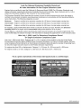
If the snowthrowerwillnot be usedfor30 daysor longer,or if it is the end of the snowseasonwhenthe last possibilityof snowis gone,the
equipmentneedsto be storedproperly.Followstorageinstructionsbelowto ensuretop performancefrom the snowthrowerfor manymoreyears.
PREPARING
PREPARING
ENGINE
Forenginesstoredover30 days:
•
Whenstoringthe snowthrowerin an unventilatedor metal storage shed,careshouldbe taken to rustprooftheequipment.Using
a light oil or silicone,coat theequipment,especiallyanychains,
springs,bearingsand cables.
•
•
Removeall dirt fromexteriorof engineand equipment.
Followlubricationrecommendations.
•
Storeequipmentin a clean,dry area.
1. Topreventgum from formingin fuel systemor on essentialcarburetor parts:
a. If fueltank containsoxygenatedor rdormulatedgasoline
(gasolineblendedwithan alcoholor ether), run engineuntilit stops
from lack of fuel.
Alcoholblendedfuels (calledgasoholor usingethanolor methanol)
canattract moisturewhich leadsto separationand formationof acids
duringstorage.Acidicgas can damagethefuel systemof an engine
_wh e n storage.
b. If fueltank containsgasoline,eitherrun engineuntilit stopsfrom
lack of fuel or add a gasolineadditiveto the gas in the tank. If you
usea gas additive,run the enginefor severalminutesto circulate
theadditivethroughthecarburetor.
Neverstoresnow throwerwith fuel in tank indoorsor in poorlyventilatedareas,wherefuel fumesmay reachan openflame,spark or pilol
lightas on a furnace,water heater,clothesdryer or gas appliance.
.
Whiletheengine is still warm,changethe oil.
3. Removethe sparkplug and pourabout 1/2 ounceof engine oil
throughthe sparkplug hole into the cylinder.Replacesparkplug
and crankthe engineseveraltimesto distributethe oil.
Neveruseengineor carburetorcleaningproductsin the fueltank or
permanentdamagemayoccur.
24
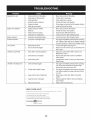
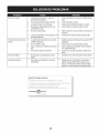
SNOW THROWER
Enginefails to start
1.
2.
Chokecontrolnot in ON position
Sparkplugwire disconnected
1.
2.
Movechokecontrolto ONposition.
Connectwireto spark plug.
3.
4.
5.
Faultysparkplug
Fueltank emptyor stale fuel
Enginenotprimed.
3.
4.
5.
Clean,adjustgap,or replace.
Filltank with clean, freshgasoline.
Primeengineas instructedin the OperationSection.
6.
Safetykeynot inserted.
6.
Insertkeyfully intothe switch.
1.
2.
Enginerunningon CHOKE
Stalefuel
3.
4.
Wateror dirt in fuel system
Carburetorout of adjustment
1.
2.
3.
Movechokecontrolto OFFposition.
Filltank with clean, freshgasoline.
Drainfueltank. Refillwith freshfuel.
4.
ContactyourSearsParts& RepairCenter.
Engineoverheats
1.
Carburetornot adjustedproperly
1.
ContactyourSearsParts& RepairCenter.
Excessivevibration
1.
Loosepartsor damagedauger
1.
Stopengineimmediatelyand disconnectsparkplug
wire.Tightenall boltsand nuts.If vibrationcontinues,
haveunitservicedbya SearsParts & RepairCenter.
Loss of power
1.
Sparkplugwire loose.
1.
Connectand tightenspark plugwire.
2.
Gascap vent hole plugged.
2.
Removeice and snow from gascap. Be certain vent
hole is clear.
1.
Drivecable in need of adjustment
1.
Adjustdrivecontrolcable. Referto Serviceand
Maintenancesection.
2.
Drivebelt looseor damaged
2.
Replacedrive belt. Referto Serviceand Maintenancesection.
3.
Wornfrictionwheel.
3.
Changefrictionwheelor contactyour SearsParts&
RepairCenter.
1.
Chuteassemblyclogged.
1.
Stopengineimmediatelyand disconnectsparkplug
wire.Cleanchuteassemblyand insideof auger
housingwith clean-outtool or a stick.
2.
Foreignobject lodgedin auger.
2.
Stopengineimmediatelyand disconnectsparkplug
wire.Removeobjectfrom augerwith clean-outtool
or a stick.
3.
Augercablein needof adjustment.
3.
Adjustaugercontrolcable. Referto Assembly
section.
4.
Augerbelt looseor damaged.
4.
Replaceauger belt. Referto Serviceand Maintenancesection.
5.
Shearpin(s) sheared.
5.
Replacewith new shearpin(s).
Enginerunserratically
Unit fails to propel itself
Unit fails to dischargesnow
25
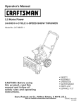
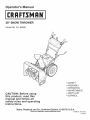
Craftsman
Snow Thrower
Model
247.88690
i
!
I
L.
--.
Y
i
_k
t\
7_
26
i\:/,
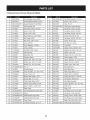
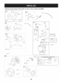
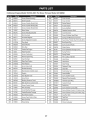
Craftsman
Snow Thrower
IViodel 247.88690
D =
731-2635
0
D =
Snow RemovalToolMount
B
684-04107-0637
SpiralAssembly,LH
684-04108-0637
SpiralAssembly,RH
0
2.
684-04057A-0637 ImpellerAssembly,12"Dia.
30.
3.
710-0347
HexScrew,3/8-16, 1.75,Gr5
31.
731-04870
Spacer,1.25OD x .75 ID x 1.00
4.
710-0451
Bolt,Carriage,5/16-18,.750Grl
32.
736-0188
Washer,Flat, .76x 1.49x .06
5.
710-04484
Screw, 5/16-18,0.750
33.
741-0493A
Bushing,Flange,.80 ID x .91OD
6.
710-0703
Screw,Carriage,1/4-20,.750,Gr5
34.
790-00087A-0637 Housing,1"Hex Bearing
7.
712-04063
Nut,FlangeLock,5/16-18,Nylon
35.
790-00118-0721
ShavePlate,2.25x 27.66
8.
712-04064
Nut,FlangeLock,1/4-20,Nylon
36.
731-05984A
Slide Shoe
9.
712-04065
Nut,FlangeLock,3/8-16, Nylon
37.
618-0123A
Housing,Auger,RH Reduced
10.
714-04040
Cotter Pin,Bow-tie
38.
618-0124A
Housing,Auger,LH Reduced
11.
725-0157
Cable,Tie, 3/16 x .05x 7.4
39.
721-0338
Seal,Oil, .750x 1.00x .125
12.
726-04012
Nut,Push-on,.25 Dia
40.
741-0662
Bearing,Flange,.75x 1.0x .59
13.
731-04705C
Chute,Adapter5" Dia
41.
710-0642
Screw,Self-tapping,1/4-20,0.750
14.
732-04460
Spring,Extension,.38 ODx 4.59
42.
711-04283
Axle,Auger,28"
1Washer,Wave,.625x .885 x .015
43.
714-0161
Key,Hi-pro3/16 x 5/8
15. J 736-0174
16.
736-0242
Washer,Bell,.340x .872x .060
44.
715-04021
Pin, Dowel,.25OD x 1.2
17.
746-04230
ClutchCable,Auger,47.23"
45.
717-04126
Shaft,Worm.75OD
18.
731-2643
SnowRemovalTool
46.
717-0528A
Gear,Worm20T
19.
738-0143
Screw,Shoulder,.498x .34,3/8-16
47.
718-04071
Collar,Thrust
20.
738-0281
Screw,Shoulder,.625x .17,3/8-16
48.
721-0325
Plug,1/4 x .437
21.
738-04124A
Shear Pin,.25 x 1.50
49.
721-0327
Seal,Oil, .75x 1 x .131
22.
741-0245
Bearing,HexFlangex .75ID
50.
736-0351
Washer,Flat, .760ID x 1.50D
23.
741-0309
Bearing,Ball,.75ID x 1.85OD
51.
736-3084
Washer,Flat, .51x 1.12
24.
756-0981B
Fiat Pulley,Idler, 2.75OD
52.
741-0663
Bearing,Flange,.75x 1.0x .925
25.
790-00075
Housing,Bearing,1.85ID
53.
741-0661A
Bearing,Flange,.75x 1.00x .975
26.
790-00080A-0637 Bracket,Auger Idlerw/Brake
54.
629-0071
ExtensionCord, 110V
27.
618-04173A
GearboxAssembly,Auger,28"
55.
710-0276
Screw,Carriage,5/16-18x 1.00
28.
684-04268-0721
HousingAssembly,Auger28"
56.
736-0159
Washer,Flat, .349x .879x .063
27
Craftsman
Snow Thrower
Model
247.88690
28
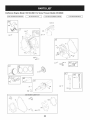
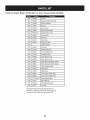
Craftsman
Snow Thrower
IViodel 247.88690
m =
D =
0
W
O
731-04869
Chute,FlangeKeeper
28.
746-04397
Cable,SpeedSelector
HandleAss'y, Engage,LH
29.
749-04191A-0637 Handle,Upper,LH
HandleAss'y, Engage,RH
30.
747-0697
Eye Bolt,ChuteCrank
31.
790-00313-0637
Shift Lever
631-04133A
HandleAssembly,ClutchLock, LH
2.
631-04134B
HandleAssembly,ClutchLock, RH
3.
684-04111B
4.
684-04112B
5.
J 631-04131B
_ ChuteAssembly(IncludesRef.# 27)
6.
710-04326
Screw,#8-16x .50
32.
731-04912B
Chute,Lower,5.0 Dia.
7.
710-3069
Screw,1/4-20,.50
33.
710-0276
Bolt, Carriage,5/16-18,1.0
8.
710-04586
Screw,1/4-20,1.625,Gr5
34.
710-04071
Bolt, Carriage,5/16-18,1.0
9.
790-00219-0721
Panel,Handle,(no cutout)
35.
710-0451
Bolt, Carriage,5/16-18,.750
10.
710-1233
Screw,Machine,#10-24,1.375
36.
731-04426A
Chute,Upper,w/Label
11.
684-04250
Pivot Rod
37.
736-0159
Washer,.349x .879x .063
12.
712-04063
Nut, FlangeLock,5/16-18,Nylon
38.
741-0475
Bushing,Plastic,.380
13. .790-00248B-0637 _ Bracket,Panel
39.
784-5647-0637
Bracket,ChuteCrank
14.
712-04081A
Nut, Hex,1/4-20,Shoulder
40.
684-04104-0637
CrankAssembly,Chute
15.
720-0274
Grip, 1.0ID x 5.0
41.
710-0449
Screw,Carriage,5/16-18,2.25
16.
720-04039
Knob,Shift,Black
42.
710-04484
Screw,5/16-18,2.25, Gr5
17.
731-04894D
Lock Plate
43.
714-0104
Pin, Cotter,.072x 1.13
18.
731-04896B
Cam,ClutchLock
44.
720-0201A
Crank Knob,1.0Dia.x 3.2, Black
19.
732-0193
Spring,.39x .60x .88
45.
720-0284
Knob,5/16-18,Black
20.
732-04219C
Spring,ClutchLock
46.
726-0100
Cap, Push,3/8 Rod
21.
732-04238
Spring,Torsion,0.8156ID x .3038
47.
735-0234
Grommet,.44 ID x .94OD x .50
736-0185
Washer,Fiat,.375x .738x .063
22.
749-04138A-0637 Handle,Lower
48.
23.
735-0199A
Bumper,Rubber,.62ODx .22
49.
749-04190A-0637 Handle,Upper,RH
714-0145
Click Pin
24.
736-0262
Washer,Fiat,.385x .870x .092
50.
25.
738-04118
Bolt, Shoulder,5/16-18x 0.905
51.
731-06471
HandlePanelCover
26.
738-04348
Screw,Shoulder,.43x 1.3, 1/4-20
52.
712-3010
Nut, Hex,5/16-18
29
Craftsman
Snow Thrower
Model
247.88690
S
//
/
/
/
//
/
3O
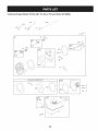
Craftsman
Snow Thrower
IViodel 247.88690
D =
0
0
D =
O
O
656-04025A
DiscAssembly,FrictionWheel
634-04148A-0911 RH WheelAssembly,15x 5 x 6
2.
684-04153
FrictionWheelAssembly,5.50D
37.
731-04873
Spacer,1.25x .75x 3.0
3.
684-04154-0637
SupportBracket,FrictionWheel
38.
738-04168
Axle, .75x 22"
4.
684-04156A
ShiftAssembly,Rod
39.
790-00218A-0637 Shift Bracket,Speed Selector
40.
710-0809
Hex Screw,1/4-20,1.25,Gr5
5.
J 710-0627
Hex Screw,5/16-24,.750,Gr5
6.
710-0788
Screw,1/4-20,1.000
41.
710-0191
Hex Screw,3/8-24, 1.25,Gr8
7.
710-1652
Screw,1/4-20x .625
42.
710-0672
Hex Screw,5/16-24,1.25,Gr5
8.
712-04065
Nut,FlangeLock,3/8-16, Nylon
43.
710-0654A
Screw,Seres,3/8-16,1.00
9.
712-0417A
Nut,Flange,5/8-18
44.
710-1245B
Hex Screw,5/16-24,.875,Gr8
710-0896
Screw,1/4-20x .625
10.
714-0126
Key,Hi Pro,3/16 x 3/4 Dia.
45.
11.
716-0104
E-ring,.500 Dia.
46.
726-04012
Nut,Push-on,.25 Dia.
12.
716-0136
E-ring,Retaining, .875Dia.
47.
731-04792A
Cover,Belt
13.
716-0231
E-ring,.750Dia.
48.
732-04308A
Spring,Torsion,.850 ID x .354
14.
717-04209A
HexShaft, .8125,7-Tooth
49.
736-0247
Washer,Flat, .406x 1.25x .157
15.
717-04230
Gear,80-Tooth
50.
736-0119
Washer,Lock .3125
LSpeed Nut,.500
51.
736-0505
Washer,Flat, .34x 1.50x .150
16. _726-0221
1_
732-0264
ExtensionSpring
52.
748-04053A
Pulley,Adapter,.75 Dia.
18.
736-0242
Washer,Bell,.340x .872x .060
53.
748-04112B
Spacer,Shoulder,.317x .50x .102
19.
736-0287
Washer,Flat,.793x 1.24x .060
54.
750-04303
Spacer,.875ID x 1.185OD
20.
736-04161
Washer,Flat,.75x 1.00x .060
55.
750-04477
Spacer,.340x .750x .360
21.
790-00289A-0637 Pit.,Cvr.
56.
754-04050
Belt,Auger Drive
22.
748-0234
ShoulderSpacer
57.
754-0367
Belt,Wheel Drive
23.
738-04184A
Screw,Shoulder,.37x .105,1/4-20
58.
756-04109
Pulley,Auger Drive,8.1x .5
24.
738-0924A
Screw,1/4-28,.375
59.
756-04113
Pulley,Half,V x 2.600 OD
25.
741-0245
Bearing,HexFlangex .75ID
60.
756-04252
Pulley,Half,3/8-V x 1.7160OD
26.
741-0563
Bearing,Ball,17x 40 x 12
61.
790-00208C
IdlerBracket,Wheel Drive
2_
746-04229
ClutchCable,Wheel,44.95"
62.
684-04169
IdlerPulleyAssembly
28.
735-04054
Rubber,FrictionWheel,5.50D
63.
750-04571
Spacer,Shoulder,.26x .79x .538
29.
748-0190
Spacer,.508ID x .75OD x .68
64.
735-04099
Plug,3/8 ID
30.
756-0625
Roller,Cable
65.
735-04100
Plug,1/2 ID
31.
790-00096-0637
FrontGuideBracket,Auger Cable
66.
712-04064
Nut,FlangeLock,1/4-20,Nylon
32.
790-00180A-0721
Frame
67.
710-0751
Hex Screw,1/4-20,.620,Gr5
33.
790-00206A-0637 Guide Bracket,AugerCable
68.
732-04311
Spring,Torsion,.750ID x .968
34.
790-00207B
Guide Bracket,Drive Cable
69.
712-04063
Nut,FlangeLock,5/16-18,Nylon
35.
790-00316-0637
Cover,Frame
70.
736-3015
Wash., Flat,.469x .875x .105
36.
634-04147A-0911 LHWheelAssembly,15 x 5 x 6
71.
790-00217A-0637 PivotBracket,SpeedSelector
31
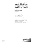
Craftsman
Engine
Model 15C103-0661
I
110580PERATOR'sMANUAL]
48 SHORT
For Snow Thrower
BLOCK
I
Model 247.88690
I 1329 REPLACEMENT
ENGINE
I
1
1330 REPAIR MANUAL
307A _
684 t)_'
21
718
22U
742 %
46
177 ,:.C,_
'
287 G_
24 0
741
598
358 ENGINE GASKET SET
2O
12
1022
993
51
883 _3
32
i
f
524 __?)
I
Craftsman
Engine
Model
15C103-0661
For Snow Thrower
1026
635
383
Model
247.88690
.......
_:[: .......
45
1029
36
238
F-_ _
1034
51
1095 VALVE GASKET SET
51 _-ii_L_
1022
993
1022
914
957
601
19o_?
33
Craftsman
Engine
Model 15C103=0661
For Snow Thrower
Model 247.88690
528
472
1196A
663_%
¢_
11
281
i'
\
",\\
604
990
564
=:_ o _
I_
604
1196
610
731
x
/
\ ....
23
1251A
347
1070 (_
1005
/
/
1252A
_'>
455
332
1036 EMISSIONS
LABEL
]
1252
300
65A_
305
_>
883
34
_,
o
Craftsman
Engine
IViodel 15C103-0661
For Snow Thrower
IViodel 247.88690
632
562 '_'*_,
209
1o54
578
851
108
\
1347
682
51
186
13___._
_- lo4_
4,.YA _9
735
365_
975_
_'_
_
137 _I[_S .... '_I
%.::::c
j
1009
276 q_
334
t
_>
....
276 _,_
121 CARBURETOR
OVERHAUL
KIT
104 _
127 _
'_,_
I
276 (_
633 _
,, ,__
.....
,!_,_, .......
.,...,,,,
_.___
_-8-J_
137
459
592 _
58
55
35
Craftsman
Engine
Model 15C103=0661
D =
For Snow Thrower
Model 247.88690
O
794188
CylinderAssembly
2
399269
Kit-Bushing/Seal(MagnetoSide)
3
299819s•
5
D =
O
690937
Screw(RewindStarter)(SAE)
65A
699228
Screw(RewindStarter)(Metric)
Seal-Oil (MagnetoSide)
95
691636
Screw(ThrottleValve)
791720
Head-Cylinder
97
690024
Shaft-Throttle
7
791716.+
Gasket-CylinderHead
98
3981850
Kit-IdleSpeed
11
695745
Tube-Breather
104
6912420
Pin-FloatHinge
12
699485•
Gasket-Crankcase
108
695807
Valve-Choke
13
699482
Screw(CylinderHead)
109
791954
Shaft-Choke
15
691686
Plug-OilDrain
117
691428
Jet-Main(Standard)
16
795116
Crankshaft
118
690048
Jet-Main(HighAltitude)
18
699696
Cover-Crankcase
121
792006
Kit-CarburetorOverhaul
20
692550.
Seal-Oil(PTOSide)
122
791717
Spacer-Carburetor
794588
Carburetor
21
281658s
Cap-OilFill
125
22
699478
Screw(CrankcaseCover/Sump)
127
6917390
Plug-Welch
23
699516
Flywheel
130
691181
Valve-Throttle
24
222698s
Key-Flywheel
133
398187
Float-Carburetor
25
791786
PistonAssembly(Standard)
134
398188
Kit-Needle/Seat
791791
PistonAssembly(.020"Oversize)
137
6939810
Gasket-FloatBowl
791787
RingSet (Standard)
146
690979
Key-Timing
791792
RingSet (.020"Oversize)
155
698214
Plate-CylinderHead
27
690975
Lock-PistonPin
177
795015
Seal-ORing(Dipstick)
28
690229
Pin-Piston
186
692317
Connector-Hose(Carburetor)
29
791783
Rod-Connecting
187
791874
Line-Fuel(Formed)
32
791784
Screw(ConnectingRod)
188
699479
Screw(ControlBracket)
33
499642
Valve-Exhaust
190
699220
Screw(FuelTank)
34
499641
Valve-Intake
192
694543
Bali-RockerArm
35
691304
Spring-Valve(Intake)
209
692571
Spring-Governor
693578
Gear-Governor
26
36
691304
Spring-Valve(Exhaust)
219
40
692194
Retainer-Valve
220
691724
Washer(GovernorGear)
793100
Bracket-Control
45
690977
Tappet-Valve
222
46
693404
Camshaft
227
794367
Lever-GovernorControl
48
N/A
ShortBlock
238
691300
Cap-Valve
51
7917180.+
Gasket-Intake
276
271716
Washer-Sealing
55
696710
Housing-RewindStarter
281
793122
58
693389
Rope-Starter
300
794728
Muffler
60
699334
Grip-StarterRope
304
699598
Housing-Blower
Panel-Control
L
36
Craftsman
Engine
IViodel 15C103-0661
For Snow Thrower
IViodel 247.88690
D =
699480
Screw(BlowerHousing)
306
695710
Shield-Cylinder
307
699483
307A
O
O
793134
Cover-Control
604A
790473
Cover-Control
Screw(CylinderShield) (M4)
608
699335
Starter-Rewind
699234
Screw(CylinderShield) (M5)
610
794614
Arrester-lntake
307B
790557
Screw(CylinderShield) (M4)
613
791972
Screw(Muffler)
309
793667
Motor-Starter
615
692576
Retainer-Governor
Shaft
318
690370
Screw(MountingBracket)
616
692547
Crank-Governor
332
792723
Nut (Flywheel)
619
699480
Screw(CylinderHeadPlate)
333
695711
Armature-Magneto
632
692653
Spring/Link-MechanicalGovernor
334
699477
Screw(MagnetoArmature)
633
691321 0
Seal-Choke/ThrottleShaft (ThrottleShft)
337
491055s
Plug-Spark
635
692927
Boot-SparkPlug
347
698338
Switch-Rocker
663
699854
Screw(ControlPanel)
356
695630
Wire-Stop
682
698039
Shield-Starter
358
791797
GasketSet-Engine
684
791761
Screw(BreatherPassageCover)
363
19203
Puller-Flywheel
689
691855
Spring-Friction
365
699484
Screw(Carburetor)
692
690572
Spring-Detent
383
19374s
Wrench-SparkPlug
718
690959
Pin-Locating(Cylinder)
455
692591
Cup-Flywheel
731
794589
Hood-Snow
456
692299
Plate-PawlFriction
731A
793643
Hood-Snow
459
281505s
PawI-Ratchet
741
695087
Gear-Timing
472
791948
Knob-ChokeShaft
742
692564
Retainer-ERing
790278
Gear-Idler
493
695744
Bracket-Mounting
746
5O5
691251
Nut (GovernorControlLever)
830
694544
Stud-RockerArm
523
790546
Dipstick
832
793193
Guard-Muffler
524
281370s
Seal-DipstickTube
836
699584
Screw(MufflerGuard)
528
793006
Hose-Primer
847
790545
Dipstick/TubeAssembly
552
692346
Bushing-GovernorCrank
851
493880s
Terminal-SparkPlug
562
691119
Bolt(GovernorControlLever)
883
691893•
Gasket-Exhaust
564
699854
Screw(ControlCover)
892
791944
Switch-Key
578
791956
WireAssembly
914
699480
Screw(RockerCover)(M6)
584
791759
Cover-BreatherPassage
914A
692557
Screw(RockerCover)(1/3 InchesLong)
585
791760
Gasket-BreatherPassage
914B
697551
Screw(RockerCover)(2/3 InchesLong)
592
690800
Nut (RewindStarter)
957
795027
Cap-FuelTank
597
691696
Screw(PawlFrictionPlate)
972
694260
Tank-Fuel
598
220624
Shim-EndPlay
975
790559
Bowl-Float
601
791850
Hose-Clamp
976
793382
Primer-Carburetor
37
Craftsman
Engine
Model 15C103-0661
For Snow Thrower
Model 247.88690
794696
KeySet
993
694088
Gasket-CylinderHeadPlate
996
794687
Shield-Carburetor
998
794701
Pipe-Oil
1005
692592
Fan-Flywheel
1009
790537
Screw(Starter Motor)
1022
691890o+
Gasket-RockerCover
1023
499924
Cover-Rocker
1026
790287
Rod-Push
1029
691230
Arm-Rocker
1034
691343
Guide-PushRod
1036
1054
Label-Emissions
280275
1058 _ 277104
Tie-Cable
_ Operator'sManual
1070
699201
Screw(FlywheelFan)
1095
791798
GasketSet-Valve
1196
696692
Screw(SnowHood)
1196A 699854
Screw(SnowHood)
1210
498144
Pulley/SpringAssembly(Pulley)
1210A 498144
Pulley/SpringAssembly(Spring)
1230
699847
Stud(Control Bracket)
1251
790555
Shield-Snow
1251A 790556
Shield-Snow
1252
699234
Screw(SnowShield)(M5)
1252A _ 699632
_ Screw(SnowShield)(M6)
1329
15Dl1140017 ReplacementEngine
1330
272147
RepairManual
1347
699200
Screw(Starter Shield)
1427
695757
Cap-Pipe
Includedin EngineGasketSet, KeyNumber358.
0 Includedin CarburetorOverhaulKit, KeyNumber121.
+ Includedin ValveGasketSet, KeyNumber1095.
38
39
(Thispage applicablein the U.S.A.and Canadaonly.)
Sears, Roebuck and Co., U.S.A. (Sears), the California Air Resources Board (CARD)
and the United States Environmental
Protection Agency (U.S. EPA)
Emission Control System Warranty Statement (Owner's Defect Warranty Rights and Obligations)
EMISSIONCONTROLWARRANTYCOVERAGEISAPPLICABLETO CERTIFIEDENGINESPURCHASEDIN CALIFORNIAIN 1995ANDTHEREAFTER,WHICHARE USEDINCALIFORNIA,ANDTO CERTIFIEDMODEL
California
and United
States
YEAR 1997AND LATERENGINESWHICHARE PURCHASEDAND USED
ELSEWHEREIN THE UNITEDSTATES(ANDAFTERJANUARY1,2001 IN
CANADA).
Emission
Control
The CaliforniaAir ResourcesBoard(CARD),U.S.EPAand Searsare pleased
to explainthe EmissionControlSystemWarrantyon your modelyear2000and
latersmalloff-roadengine(SORE).In California,newsmall off-roadengines
mustbe designed,builtand equippedto meetthe State'sstringentanti-smog
standards.Elsewherein the UnitedStates, newnon-road,spark-ignition
enginescertifiedfor modelyear 1997and latermustmeetsimilar standardsset
forth bythe U.S.EPA.Sears mustwarrantthe emissioncontrol systemon your
Sears Emission
Control
Statement
parton yourengineis defective,the part will be repairedor replacedbySears.
Warranty
Responsibilities
Asthe smalloff-roadengine owner,you are responsiblefor the performanceof
the requiredmaintenancelistedin yourOperatingand MaintenanceInstructions.Searsrecommendsthatyou retain all yourreceiptscoveringmaintenance
on yoursmalloff-roadengine,but Sears cannotdenywarrantysolelyfor the
lackof receiptsor for yourfailureto ensurethe performanceof all scheduled
maintenance.As the smalloff-roadengineowner,you shouldhoweverbe
awarethat Searsmay denyyou warrantycoverageif your smalloff-roadengine
or a part hasfailed dueto abuse,neglect,impropermaintenanceor unap-
Sears Emission
Warranty
Defects Warranty Coverage
Smalloff-roadenginesarewarrantedrelativeto emissioncontrol partsdefects
fora periodof one year,subjectto provisionsset forth below.Ifany covered
Owner's
Defects
enginefor the periodsoftime listedbelow,providedtherehas been noabuse,
neglector impropermaintenanceof your smalloff-roadengine.Youremission controlsystemincludespartssuch as the carburetor,air cleaner,ignition
system,mufflerand catalyticconverter.Also includedmay be connectorsand
otheremissionrelatedassemblies.Wherea warrantableconditionexists,Sears
will repairyour smalloff-roadengineat no costto you includingdiagnosis,parts
and labor.
provedmodifications.You
are responsiblefor presentingyour smalloff-road
engineto an AuthorizedSearsServiceDealeras soonas a problemexists.The
undisputedwarrantyrepairsshouldbe completedina reasonableamountof
time,not to exceed30 days. Ifyou haveany questionsregardingyourwarranty
rightsand responsibilities,you shouldcontacta SearsService Representative
at 1-800-469-4663.
The emissionwarrantyis a defectswarranty.Defectsare
judged on normalengineperformance.Thewarrantyis not relatedto an in-use
emissiontest.
Control Defects Warranty Provisions
Thefollowingarespecificprovisions
relativetoyourEmission
ControlDefectsWarranty
Coverage.
It isin addition
totheSearsenginewarranty
fornon-regulated
enginesfound in the Operatingand MaintenanceInstructions.
1. WarrantedParts
3. NoCharge
Repairor replacementof anyWarrantedPartwill be performedat no
chargeto the owner,includingdiagnosticlabor whichleads to the
determinationthata WarrantedPartis defective,if the diagnosticwork is
performedat an AuthorizedSears ServiceDealer.For emissionswarranty
servicecontact yournearestAuthorizedSears ServiceDealeras listed in
the "YellowPages"under"Engines,Gasoline,""GasolineEngines,""Lawn
Mowers,"or similar category.
4. Claimsand CoverageExclusions
Warrantyclaimsshall be filed in accordancewiththe provisionsof the
Sears EngineWarrantyPolicy.Warrantycoverageshall be excludedfor
failuresof WarrantedPartswhichare not original Sears partsor because
of abuse, neglector impropermaintenanceas setforth inthe Sears
EngineWarrantyPolicy.Sears is not liableto coverfailuresof Warranted
Partscausedby the use of add-on, non-original,or modifiedparts.
5. Maintenance
Coverageunderthis warrantyextendsonly to the parts listedbelow (the
emissioncontrolsystemsparts)to the extentthese partswere presenton
the engine purchased.
a. FuelMeteringSystem
• Cold start enrichmentsystem
• Carburetorand internalparts
• FuelPump
b. Air lnduction System
• Air cleaner
• Intakemanifold
c. IgnitionSystem
• Spark plug(s)
• Magnetoignitionsystem
d. CatalystSystem
• Catalyticconverter
• Exhaustmanifold
Any WarrantedPart whichis not scheduledfor replacementas required
maintenanceor whichis scheduledonly for regularinspectionto the effect
of "repairor replaceas necessary"shallbe warrantedasto defectsfor the
warrantyperiod.Any WarrantedPartwhich is scheduledfor replacement
as requiredmaintenanceshallbe warrantedasto defectsonly forthe
periodof time up to the first scheduledreplacementfor that part. Any
replacementpart that is equivalentin performanceand durabilitymay
be usedin the performanceof any maintenanceor repairs.The owneris
responsibleforthe performanceof all requiredmaintenance,as definedin
the SearsOperatingand MaintenanceInstructions.
6. ConsequentialCoverage
Coveragehereundershallextend to the failure of any engine components
caused bythe failureof any WarrantedPartstill underwarranty.
• Air injectionsystemor pulsevalve
e. MiscellaneousItemsUsedin AboveSystems
• Vacuum,temperature,position,time sensitivevalves
andswitches
• Connectorsandassemblies
2. Lengthof Coverage
Searswarrantsto the initialownerand eachsubsequentpurchaserthat
the WarrantedParts shallbe free from defects in materialsandworkmanshipwhich causedthe failure of the WarrantedPartsfor a periodof one
yearfrom the datethe engineis deliveredto a retailpurchaser.
Inthe USAandCanada,a 24 hour hot line, 1-800-469-4663,has a menu of pre-recordedmessagesofferingyou enginemaintenanceinformation.
GDOC-100188Rev.A
40
Look For Relevant Emissions Durability Period and
Air index information On Your Engine Emissions Label
Engines that are certified to meet the California Air Resources Board (CARB) Tier 2 Emission Standards must
display information regarding the Emissions Durability Period and the Air Index. Sears, Roebuck and Co., U.S.A.
makes this information available to the consumer on our emission labels.
The Emissions Durability Period describes the number of hours of actual running time for which the engine is
certified to be emissions compliant, assuming proper maintenance in accordance with the Operating & Maintenance Instructions. The following categories are used:
Moderate:
Engine is certified
to be emission compliant
for 125 hours of actual engine running time.
Intermediate:
Engine is certified
to be emission compliant
for 250 hours of actual engine running time.
Extended:
Engine is certified
to be emission compliant
for 500 hours of actual engine running time.
For example, a typical walk-behind lawn mower is used 20 to 25 hours per year. Therefore, the Emissions
Durability Period of an engine with an intermediate rating would equate to 10 to 12 years.
The Air Index is a calculated number describing the relative level of emissions for a specific engine family. The
lower the Air Index, the cleaner the engine. This information is displayed in graphical form on the emissions label.
After
After July 1, 2000 certain
Environmental Protection
sions Compliance Period
for which the engine has
July 1,2000, Look For Emissions
Compliance
On Engine Emissions
Compliance
Label
Period
Sears, Roebuck and Co., U.S.A. engines will be certified to meet the United States
Agency (USEPA) Phase 2 emission standards. For Phase 2 certified engines, the Emisreferred to on the Emissions Compliance label indicates the number of operating hours
been shown to meet Federal emission requirements.
For engines less than 225 cc displacement,
For engines of 225 cc or more, Category
Category
C = 125 hours, B = 250 hours and A = 500 hours.
C = 250 hours, B = 500 hours and A = 1000 hours.
This is a generic representation of the emission label typically found on a certified engine.
FAMILY YBSXS.3192VA
274812
GDOC-100182
Rev.A
41
Congratulationson makinga smartpurchase.YournewCraftsman@
productis designedand manufacturedfor yearsof dependableoperation. But likeall products,it may requirerepairfrom time to time.That's
whenhavinga RepairProtectionAgreementcansave youmoneyand
aggravation.
Here'swhat the RepairProtectionAgreement*includes:
* Expert service byour 10,000professionalrepairspecialists
o Unlimitedserviceand no chargefor partsand laboron all
coveredrepairs
o Product replacementup to $1500if yourcoveredproductcan't be
fixed
• Discountof 10%from regularprice of serviceand relatedinstalled
parts notcoveredby theagreement;also, 10%off regularpriceof
preventivemaintenancecheck
• Fast help by phone- we call it RapidResolution- phone support
from a Searsrepresentative.Thinkof usas a "talkingowner's
manual."
Onceyou purchasethe Agreement,a simplephonecall is all that it
takesfor youto scheduleservice.Youcan call anytimedayor night,or
schedulea serviceappointmentonline.
The RepairProtectionAgreementis a risk-freepurchase.If youcancel
for any reasonduringthe productwarrantyperiod,wewill providea full
refund.Or,a proratedrefundanytimeafter the productwarrantyperiod
expires.Purchaseyour RepairProtectionAgreementtoday!
Somelimitationsand exclusionsapply. For pricesand additional
informationin the U.S.A. call 1-800-827-6655.
*Coverage in Canadavaries on some items. Forfull details call
Sears Canadaat 1-800-361-6665.
Sears Installation Service
ForSearsprofessionalinstallationof homeappliances,garagedoor
openers,waterheaters,and othermajorhomeitems,in the U.S.A.or
Canadacall 1-800-4-MY-HOME®.
42
Declaraci6n de garantia ............................ Pagina
Practicas operaci6n seguras ..................... Pagina
Montaje ......................................................
Pagina
Operaci6n ..................................................
Pagina
Servicio y Mantenimiento .......................... Pagina
Almacenamiento fuera de temporada ....... Pagina
GARANTiA
Dos Ahos en Lanzador
43
44
48
52
56
64
Soluci6n de problemas .............................. Pagina 65
Acuerdo de protecci6n para reparaciones .... Pagina 69
Etiquetas de seguridad .............................. Pagina 7
Lista de piezas ........................................... Pagina 26
NOmero de servicio ................................... Cubierta
posterior
LIMITADA
CRAFTSMAN
de Nieve
Cuandohechofuncionary mantenidosegQntodas lasinstrucciones
suministradas,si este lanzadorde nievefalla debidoa un defectoen material o habilidaddentrode dosa_osde la fechao compra,Ilame 1-800-4MYHOMEhacerlosarreglospara reparaci6nlibre.
Estagaranfias61otendr_validezdurante90 dias si este productose utilizaen cualquiermomentopara fines comercialeso de alquiler.
Duranteel primera_o de la compra,no habr_ningOnpreciopara el serviciode garanfiaen sucasa. Parasu conveniencia,en de casa el servicio
de garanfiatodaviaestar_disponibledespu_sdel primera_o de la compra,pero un preciode viaje se aplicar& Estepreciosera renunciado
si ustedtransportaal lanzadorde nievea una posici6nde bajadade Artesanoautorizada.Parala posici6nautorizadam_s cercana,Ilame
1-800-4-MY-HOME
®.
Esta garantiacubreSOLO defectos en material y habilidad.Sears no pagar_para:
•
Losarficulosprescindiblesque se hacenIlevadospuestosduranteel uso normal,incluso,perono limitadospara patinarzapatos,platode
afeitado,esquilanalfileres,buj[a,filtro de aire,cinturones,y filtro del aceite.
•
•
Revisi6nde mantenimientoest_ndar,cambiosde aceite,o puestasa punto.
Reemplazode neum_ticoo reparaci6ncausadapor pinchazosdesdefuerade objetos,como u_as,espinas,tocones,o cristal.
•
•
Neum_ticoo reemplazode ruedao reparaci6nque resultade ropanormal,accidente,u operaci6nimpropiao mantenimiento.
Las reparacionesnecesariasdebidoal abusode operador,inclusoperono limitadoparada_ar causadoafectandoobjetosque doblanel
marcoo el cigOe_al,o el sobreexcesode velocidaddel motor.
Reparacionesnecesariasdebidoa negligenciadel operador,incluyendo
entre otros,da_osmec_nicoy el_ctricoocasionadopor un
almacenamientono apropiado,falla por el usode aceitede grado y/o cantidadno apropiadao fallapor no dar mantenimientoal equipode
acuerdocon las instrucciones
contenidasen el manualdel operador.
•
•
•
Limpiezao reparacionesal motor(sistemade combustible)provocadaspor un combustiblecontaminadou oxidado(viejo).En general,el
combustibledebe utilizarseen un perbdo no mayorde 30 d[as a partirde su adquisici6n.
El empejoramientonormaly la ropade losfines exteriores,o productoetiquetanel reemplazo.
Estagaranfias61otendrAvalidezmientrasel productose utiliceen los EstadosUnidos.
Estagaranfiale otorgaderechoslegalesespedficos,pero ustedpodr[agozarde otros derechosen raz6nde su lugarde residencia.
Sears, Roebuck and Co., HoffmanEstates, IL 60179
Tipode aceitedel motor:
Capacidadde aceitedel motor:
SAE 5W-30
Capacidadde combustible:
Bujfas:
3 cuartos
N_mero de modelo ..........................................................
N_mero de serie ..............................................................
Fechade compra .............................................................
Champion® RC12YC
.030"
Registrearriba el nOmerodel modelo,el nOmerode seriey la fecha
de compra
Separaci6nde lasbujias:
20 onzas
© Sears Brands,LLC
43
Esta rn_.quinarueconstruidapara seroperadade acuerdocon
las reglasde seguridadcontenidasen este manual.AI igualque
concualquiertipo de equipo rnotorizado,un descuidoo error por
partedel operadorpuedeproducirlesionesgraves.Estarn_.quina
es capazde arnputarrnanosy piesy de arrojarobjetoscon gran
fuerza.De no respetarlas instruccionesde seguridadsiguientesse
puedenproducirlesionesgraveso la rnuerte.
La presenciade este sirnboloindicaque setrata de instrucciones
irnportantesde seguridadque se deben respetarpara evitar
poneren peligrosu seguridadpersonaly/o materialy la de otras
personas.Lea y sigatodas lasinstruccionesde este manualantes
de poneren funcionarnientoesta rn_.quina.Si no respetaestas
instruccionespodria provocarlesionespersonales.Cuandoveaeste
sirnbolo,i presteatenci6na la advertencia!
PROPOSICI6N
65 DE CALIFORNIA
Su responsabilidad--Restrinja
el usode esta rn_.quina
rnotorizadaa las personasque lean,cornprendany respetenlas
advertenciase instruccionesque aparecenen este manualy en la
rn_.quina.
El escapedel motorde este producto,algunosde sus cornponentes
y algunoscornponentesdel vehiculocontieneno liberansustancias
quirnicasque el estadode Californiaconsideraque puedenproducir
c_.ncer,defectosde nacirnientou otros problernasreproductivos.
iGUARDE
ESTAS
INSTRUCCIONES!
CAPACITACION
PREPARATIVOS
•
Lea,entienday curnplatodaslas instruccionesincluidasen
la rn_.quina
y en los rnanualesantesde rnontarlay utilizarla.
Guardeeste manualen un lugarseguropara consultasfuturasy
peri6dicas,asi cornopara solicitarrepuestos.
Lea el Manualdel Operadory sigatodas las advertenciase
instrucciones
de seguridad.El fracasode hacerasi puedecausar
la heridaseriaal operadory/o personaspresentes.Para Ilarnada
de preguntas,1-800-659-5917.
Inspeccionerninuciosarnente
el _.readondeutilizar_,el equipo.Saque
todos los felpudos,peri6dicos,trineos,tablas,cables y otrosobjetos
extra_oscon los que podriatropezaro que podrianser arrojadospor
la barrena/ irnpulsor.
•
Paraprotegerselosojos utilice siernpreanteojoso antiparras
de seguridadrnientrasopera la rn_.quina
o rnientrasla ajusta
o repara.Losobjetosarrojadosque rebotanpuedenproducir
lesionesocularesgraves.
Farniliaricesecontodos los controlesy con el usoadecuado
de losrnisrnos.Sepa c6rnodetenerla rn_.quinay desactivarlos
controlesr_.pidarnente.
No perrnitanuncaque losni_os rnenoresde 14a_osutilicen
esta rn_.quina.Los ni_osde 14a_osen adelantedebenleer y
entenderlas instruccionesde operaci6ny norrnasde seguridad
contenidasen este manual,yen la rn_.quina
ydebenserentrenadosy supervisadospor un adulto.
•
•
•
•
•
•
•
•
•
•
Nuncaperrnitaque los adultosoperenesta rn_.quinasin recibir
antesla instrucci6napropiada.
Losobjetosarrojadospor la rn_.quinapuedenproducirlesiones
graves.Planifiqueel patr6nen el que va air arrojandonievepara
evitarque la descargade materialse realicehacialos carninos,
los observadores,etc.
Mantengaa los observadores,ayudantes,rnascotasy ni_ospor
Io rnenosa 75 piesde la rn_.quinarnientrasla rnisrnaest,. en
funcionarniento.Detengala rn_.quinasialguien se acerca.
•
Sea precavidopara evitarpatinarseo caerseespecialrnente
cuandoopera la rn_.quina
en reversa.
44
Noopere la rn_.quinasin la vestirnentaadecuadaparaestar al
aire libreen invierno.No utilicealhajas,bufandaslargasu otras
prendassueltasque podrianenredarseen las partes rn6viles.
Utiliceun calzadoespecialpara superficiesresbaladizas.
Useun prolongadory un tornacorrientede tres cablescon
conexi6na tierra paratodas las rn_.quinascon rnotoresde
encendidoel_ctrico.
Ajuste la alturade la caja del tornacorrientepara lirnpiarla grava
o las superficiescon piedrastrituradas.
Desengranetodas las palancasde controlantesde arrancarel
motor.
•
Nuncaintenterealizarajustesrnientrasel motorest,. en rnarcha
exceptoen los casosespedficarnenterecornendadosen el
manualdel operador.
•
Dejeque el motory la rn_.quinaseadaptena la ternperatura
exteriorantes de cornenzara sacarla nieve.
Manejo seguro de la gasolina
Paraevitar lesionespersonaleso daSosmaterialestengamucho
cuidadocuandotrabajecon gasolina.La gasolinaes sumamente
infiamable
y sus vaporespuedencausarexplosiones,Si se derrama
gasolinaencimao sobrela ropase puede lesionargravementeya que
se puedeincendiar,L&vesela piel y c&mbiesede ropade inmediato,
•
Nuncaopere la m_.quinasi falta un montajedel canalo si el
mismoest,. da_ado.Mantengatodos losdispositivosde seguridad en su lugary en funcionamiento.
Nuncaenciendael motoren espacioscerradoso en una zona
con pocaventilaci6n.El escapedel motorcontienemon6xidode
carbono,un gas inodoroy letal.
•
•
Utilices61olos recipientesparagasolinaautorizados.
Apaguetodoslos cigarrillos,cigarros,pipasy otras fuentesde
combusti6n.
•
•
Noutilice la m_.quinabajola influenciadel alcoholo las drogas.
El silenciadory el motorse calientany puedencausarquemaduras. Nolos toque. Mantengaa los ni_osalejados.
•
•
Nuncacarguecombustibleen la m_.quinaen un espado cerrado,
Nuncasaquela tapa del combustibleni agreguecombustible
mientrasel motorest&calienteo en marcha.
•
•
Dejeque el motorse enfriepor Iomenosdos minutosantesde
volvera cargarcombustible,
NuncaIleneen excesoel dep6sitode combustible.Lleneel
tanquea no m_.sde 1/2pulgadapor debajode la basedel cuello
de Ilenadodejandoespaciopara la dilataddn del combustible,
Vuelvaa colocarla tapade la gasolinay ajQstelabien,
•
Seasumamenteprecavidocuandoopere la m_.quinasobreuna
superficiecon gravao cuandola cruce.Mant_ngasealerta por si
sepresentanpeligrosocultoso tr_.nsito.
Tengacuidadocuandocambiede direcci6no cuandooperela
m_.quinaen pendientes.
Limpieel combustibleque se hayaderramadosobreel motory el
equipo.Trasladela m_.quinaa otra zona, Espere5 minutosantes
de encenderel motor,
•
•
•
•
•
•
•
•
•
Nuncaalmacenela m_.quinao el redpientede combustibleen
un espaciocerradodonde hayafuego,chispaso luz piloto(por
ejemplo,hornos,calentadoresde agua,calefactores,secadores
de ropa,etc.),
•
•
Dejeque la m&quinase enfriepor Io menos5 minutosantesde
guardarla,
NuncaIlenelos recipientesen el interiorde un vehiculoo camidn
o cajade remolquecon recubrimientospl&sficos.Coloque
siemprelos redpientesen el pisoy lejosdel vehiculoantesde
Ilenarlos.
Si es posiNe,retireel equipoa gasolinadel cami6no remolque
y II_neloen el suelo,Si esto no es posiNe,Ileneel equipoen un
remolqueconcontenedorport_.til,en vez de desdeuna boquilla
dispensadorade gasolina.
Mantengala boquilladispensadoraen contactocon el hordedel
depdsitode combustibleo con la aberturadel recipienteen todo
momento,hastaterminarla carga. No utiliceun disposifivode
apertura/derrede boquilh,
•
•
•
•
FUNCIONAMIENTO
•
No pongalas manoso los piescerca de las piezas rotatorias,
en la cajade la barrena/ impulsoro en el montajedel canalde
descarga,Hacercontactocon piezasgiratoriaspuederesultaren
la amputacidnde manoso pies.
•
La palancade controlde la barrena/ impulsores un disposifivo
de seguridad,Nuncaevite su funcionamiento,De hacerlola
operad6n de la m_.quinaes riesgosay puedeocasionarlesiones,
Las palancasde control debenfuncionarbienen ambasdirecclonesy regresarautom_.ticamente
a la posicidnde desengrane
cuandose las suelta,
•
45
•
•
Planifiqueel patr6nen el que va air arrojandonievepara evitar
que la descargade materialse produzcahacialas ventanas,
lasparedes,losautom6viles,etc.y evitarasi posiblesda_os
materialeso lesionesproducidaspor los rebotes.
Nuncadirija la descargahacialos ni_os,los observadoreso las
mascotasni deje que nadiese pare delantede la m_.quina.
Nosobrecarguela capacidadde la m_.quinatratandode sacarla
nievemuy r_.pidamente.
Nuncaopere esta m_.quinasin buenavisibilidado iluminaci6n.
Siempredebe estar segurode que est,. bien afirmadoy sujetandofirmementelasmanijas.Camine,nuncacorra.
Cortela corrientea la barrena/ impulsorcuandotransportela
m_.quinao cuandola mismano est,. en uso.
Nuncaopere la m_.quinaa alta velocidadde desplazamiento
sobresuperficiesresbaladizas.Mirehaciaabajoy haciaatr_.sy
tengacuidadocuandovaya marchaatr_.s.
Si la m_.quinacomenzaraa vibrarde maneraanormal,detengael
motor,desconecteel cablede la bujiay p6ngalade maneraque
hagamasacontra el motor.Inspeccionela m_.quinaminuciosamenteparavet si est,. da_ada.Reparetodos los da_osantesde
encendery operarla m_.quina.
Desengranetodaslas palancasde controly detengael motor
antes de dejar la posici6nde operaci6n(detr_.sde las manijas).
Esperea que la barrena/ impulsorse detengapor completo
antes de destaparel montajedel canalo realizarajustese
inspecciones.
Nuncapongalas manosen lasaberturasde descargao de
recolecci6n.Utilicesiemprela herramientade limpiezaque se
adjuntaparadestaparla aberturade descarga.Nodestapeel
montajedel canal mientrasel motorest,. en funcionamiento.
Antes de destaparlo,apagueel motory permanezcadetr_.sde las
manijashasta quetodas las partes m6vilesse hayandetenido.
Uses61ounionesy accesoriosaprobadospor el fabricante(por
ejemplo,pesaspara las ruedas,cadenaspara los neum_.ticos,
cabinas,etc.).
•
•
Paraencenderel motor,jab de la cuerdalentarnentehastaque
sientaresistencb, luegojab r_.pidarnente.
El replieguer_.pidode
la cuerdade arranque(tensbn de retroceso)le jalar_,la rnanoy
el brazohaciael motor rn_.sr_.pidode Io que usted puedesoltar.
El resultadopuedenserhuesos robs, fracturas,hernatornaso
esguinces.
Si se presentansituacionesque no est&nprevistasen este
manual,seacuidadosoy useel sentidocornQn.P6ngaseen
contactocon Asistenciaal Clientepara solicitarayuday el
nornbredel distribuidorde serviciorn_.scercano.
MANTENIMIENTO
•
•
•
Y ALMACENAMIENTO
Nuncaalterelos dispositivosde seguridad.Controleperi6dicarnenteque funcionencorrectarnente.Rernitasea las secciones
de rnantenirniento
y ajustede este manual.
Antesde realizarla lirnpieza,repararo revisarla rn_.quina,
desengranetodaslas palancasde controly detengael motor.
Esperea que la barrena/ irnpulsorsedetengapor cornpleto.
Desconecteel cable de la bujia y p6ngalohaciendornasacontra
el motorparaevitar que se enciendaaccidentalrnente.
•
SegOnla Cornisi6nde Seguridadde Productosparael Consurnidorde los EstadosUnidos(CPSC)y la Agenciade Protecci6n
Arnbientalde los EstadosUnidos(EPA),este productotieneuna
vida Qtilmediade siete (7) a_os,6 60 horasde funcionarniento.
AI finalizarla vidaOtilmedia,adquierauna rn_.quinanuevao
haga inspeccionaranualrnente_sta por un distribuidorde servicio
autorizadopara cerciorarsede que todoslos sisternasrnec_.nicos
y de seguridadfuncionancorrectarnentey no tienenexcesivo
desgaste.Si no Io hace, puedenproducirseaccidentes,lesiones
o rnuerte
•
Nuncaalrnacenela rn_.quina
o el recipientede combustibleen un
espaciocerradodonde hayafuego,chispaso luz pilotocornopor
ejernplo,calentadoresde agua,hornos,secadoresde ropa,etc.
•
Consultesiernpreel manualdel operadorparaobtener
instruccionesadecuadaspara el almacenarnientofuerade
ternporadaVerifique
frecuenternentela linea de combustible,el
tanque,el tap6n,y losaccesoriosbuscandorajaduraso perdidas.
Reernplacede ser necesario.
Nod_ arranqueal motorsi no est,. la bujia de encendido.
•
NO MODIFIQUE
Controlefrecuenternenteque todos lospernosy tornillosest_n
bien ajustadosparacornprobarque la rn_.quinase encuentra
en condicionessegurasde funcionarniento.Adern_.s,haga una
inspecci6nvisualde la rn_.quinapara verificarsi est,. daSada.
Nocarnbiela configuraci6ndel reguladordel motorni acelere
dernasiadoel rnisrno.El reguladordel motorcontrolala veloddad
rn_.xirnasegurade funcionarnientodel motor.
Las placasde raspadoy las zapatasantideslizantesque se
usancon la rn_.quina
quitanievese desgastany se daSan.
Paraprotegersuseguridad,verifiquefrecuenternentetodos los
cornponentesy reernpl&celoss61ocon partesde losfabricantes
de equiposoriginales(OEM)."iEI usode piezasque no curnplen
con lasespecificacionesdel equipooriginal puederesultaren
rendirnientoinadecuadoadern_.sde poneren riesgola seguridad!"
EL MOTOR
Paraevitarlesionesgraveso la rnuerte,no rnodifiqueel motorbajo
ningunacircunstancia.Si carnbiala configuraci6ndel reguladorel
motor puededescontrolarsey operara velocidadesinseguras.Nunca
carnbiela configuraci6nde f_.bricadel reguladordel motor.
AVISO REFERIDO
A EIVlISIONES
Losrnotoresque est_.ncertificadosy curnplencon las regulaciones
de ernisionesfederalesEPAy de CaliforniaparaSORE(Equipos
peque_ostodoterreno)est_.ncertificadosparaoperar congasolina
cornQnsin plornoy puedenincluirlos siguientessisternasde control
de ernisiones:Modificaci6nde motor(EM) y catalizadorde tres vbs
(TWO) siest_.nequipadosde esa rnanera.
GUARDACHISPAS
Reviselas palancasde controlperi6dicarnentepara verificar
que engraneny desengranenadecuadarnentey ajOstelossi es
necesario.Consultela secci6nde ajustesde este manualdel
operadorpara obtenerinstrucciones.
Mantengao reernplacelasetiquetasde seguridade instrucciones
segOnseanecesario.
Respetelas norrnasreferentesa la disposici6ncorrectay las
reglarnentacionessobregasolina,aceite,etc. para protegerel
medicarnbiente.
Antesde alrnacenarla rn_.quinaenci_ndalaunosrninutospara
sacar la nieveque hayaquedadoen la rnisrnay para evitarasi
que se congelela barrena/ irnpulsor.
Esta rn_.quinaest,.equipadacon un motorde cornbusti6ninternay
no debe ser utilizadaen o cercade un terrenoagrestecubiertopor
bosque,rnalezaso hierbaexceptosi el sisternade escapedel motor
est,. equipadocon un arnortiguadorde chispasque curnplacon las
byes localeso estatalescorrespondientes,en caso de haberlas.
Si se utiliza un arnortiguadorde chispasel operadorIo debe rnantener
en condicionesde usoadecuadas.Enel Estadode Californialas
rnedidasanteriorrnenternencionadassonexigidaspor Icy (Arficulo
4442 del C6digode RecursosPOblicosde California).Esposible
que existanbyes sirnilaresen otros estados.Lasbyes federalesse
aplicanen territoriosfederales.
Puedeconseguirel arnortiguadorde chispasparael silenciadora
travesde su distribuidorautorizadode rnotoreso poni_ndoseen
contactoconel departarnentode servicios.
46
SiMBOLOS
DE SEGURIDAD
Esta p_ginadescribelossirnbolosy figurasde seguridadinternacionalesque puedenapareceren este producto.Lea el manualdel operador
)araobtenerla inforrnaci6nterrninadasobreseguridad,reunirse,operaci6ny rnantenimientoy reparaci6n.
i
LEA ELMANUAL DELOPERADOR(S)
Lea,entienda, y siga todas lasinstrucciones en el manual (es)antes de intentar reunirse y funcionar.
i
LA ADVERTENCIA --
PLATOS ROTATORIOS
Guarde manos de entrada y aperturas
de la descarga mientras
la m_iquina corre. Alli ellos hacen para
girar platos dentro.
LA ADVERTENCIA-- LAMINAS ROTATIVAS
Guarde manos de entrada y aperturas de descarga mientras la m_iquina corre. Alli hacen girar I_iminas
dentro.
LA ADVERTENCIA -- TALADRO ROTATIVO
No ponga manos o pies cerca del giro de partes, en el alojamiento
tolva. Contacto
con las partes rotativas
OBJETOS LANZADOS
Esta m_iquina
puede amputar
de taladro/aspa
o asamblea
de
manos y pies.
POR ADVERTENCIA
puede recoger y lanzar y objetos
que pueden
causar la herida personal
seria.
GASOLINA DE ADVERTENCIA ESINFLAMABLE
Permita que el motor se enfrie al menos dos minutos
ADVERTENCIA
--
MONOXIDO
Nunca dirijas un motor dentro
contienen
el mon6xido
antes del reabastecimiento
de combustible.
DE CARBONO
o en un _irea mal ventilada.
de carbono, un gas inodoro
ADVERTENCIAELECTROCHOQUE
No use eljuez de salida el_ctrico del motor en la Iluvia.
47
Los gases de combusti6n
y mortal.
de motor
NOTA:las referenciasal lado derechoo y ciertosde la rn_.quina
quitanievesedeterrninandesdela parteposteriorde la unidaden
posici6nde operaci6n(perrnaneciendodirectarnentedetr_.sde la
rn_.quinaquitanieve,rnirandohaciael panelde la rnanija).
EXTRACCI6N
1.
DE LA UNIDAD
DE LA CAJA
2.
Corte lasesquinasde la cajade cart6ny exti_ndalaen el piso
Quitey descartetodos los insertosde ernpaque.
Saquela rn_.quina
quitanievede la caja.
3.
AsegQresede vaciarcornpletarnentela cajaantes de tirarla.
PARTES
SU ELTAS
Coneste manualse incluyendos pasadoresde cuchiNade barrenade
repuesto.Consultela secci6n"Barrenas"en la secci6nde Servicioy
Mantenirnientopara obtenerrn_.sinforrnaci6nsobreel reernplazode
los pasadoresde cuchillade barrena.
MONTAJE
,
2.
\
Coloquela palancade carnbiosen la posici6nde avance(F) 6.
Figura1
Observeel _.reainferiortraserade la rn_.quina
quitanievepara
asegurarsede que arnboscablesest_n alineadoscon las gufas
rotatoriasantes de girar la rnanijahaciaarriba.Vea la figura1.
f
NOTA:AsegQresede que losextrernossuperioresde cadacable
est_.ncorrectarnenteasentadosen susoporte.
,
Asegurela rnanijaajustandola perilla a rnariposade pl_.stico
situadaen los ladosizquierdoy derechode dicha rnanija.Vea la
figura2. Retirey descartetodos lasbandasde pl_.stico,si Las
hubiera.Unicarnentese utilizanparael ernpaque.
!
/
/
/
Figura2
48
.
5.
SitOeel montajedel canalsobrela base.Vea la figura3.
Cierrelos fijadoresde la bridapara asegurarel montajedel canal
a la basedel canal. Veala figura4. Losfijadoresde la brida
emitenun chasquidocuandoest_.nbien asegurados.
NOTA:si los fijadoresde la brida no seajustanen su lugarf_.cilmente,
utilice la palmade su rnanopara apfcar una presi6nr_.piday firmeen
la parteposteriorde cadauno.
.
a.
b.
Quitela arandelaplanay el brochede horquila del extremo
del controldireccionaldel canal.
Inserteel extremodel controldireccionaldel canalenel soporte
inferiory asegOrelo
mediantela arandelaplanay el broche
de horquilaqueacabade retirar.Veala figura5. Si es
necesario,puedeajustarseel soporteinferior.Consute"Ajuste
del soportedelcanal"en la secci6nde Servicioy
Mantenimiento.
Figura4
Figura3
Figura5
49
CONFIGURACION
Herramienta
"_
de Limpieza
"
del Canal
Hay una herramientade limpiezadel canal iajustadaa la parte
superiorde la caja de la barrenacon un pasadorde ensamNado.Vea
la figura6. La herramientaest,. diseSadapara limpiarel hieloy la
nievedel montajede un canal.Este productose sujeta medianteuna
uni6nde cableen la f_.brica.Corte la uni6n de cableantes de operar
la mAquinaquitanieve.
Herrarnienta de
Lira _ieza del Canal
Nuncausesus manospara liberar un montajede canaltapado.Apague el motory permanezcadetr_.sde las manijashasta que todas
las partes m6vilesse hayandetenidoantesde utilizarla herramienta
de limpiezaparalimpiarel montajedel canal.
Presi6n
de los neumaticos
Antesde cualquieroperaci6n,compruebela presi6nde ambos
neumAticosy reduzcala mismaa entre15 psiy 20 psi.
Figura6
NOTA:Si la presi6nde los neum&ticosno es igualen ambosneum&ticos,es posibleque la unidadno siga una trayectoriarectay que la
placade raspadose desgastede formadespareja.
f
AJUSTES
Zapatas
/
antideslizantes
Laszapatasantideslizantesde la m_.quinaquitanieveseajustan para
arribaen f_.bricapara el envio. Si Iodesea,puedeajustarlashacia
abajoantes de hacerfuncionarla m_.quinaquitanieve.
recomienda
esta
sobre
ya que es posibleque la m_.quinaquitanievetome la gravasueltay
la barrenala
expulse,Io
cual podriacausarlesionespersonaleso
lNo
se
que opere
m_.quinaquitanieve
grava,
da_ar la m_.quinaquitanieve.
•
•
Si deseaquitarnieveal rasdel suelo,elevem_.slaszapatas
antideslizantesen la cajade la barrena.
Use las posicionesmediao bajacuandola superficieque desee
limpiarseadespareja,como un caminode grava.
NOTA:Si tieneque usar la m_quinaquitanievesobregrava,mantenga
la zapata antideslizanteen la posici6nm_.selevadapara Iograruna
separaci6nm_ximaentreel pisoy la placade raspado.
Paraajustar laszapatasantideslizantes:
1. Aflojelas cuatrostuercashexagonales(dosen cada lado)y los
pernosdel carro. Muevalas zapatasantideslizantesa la posici6n
deseada.
2.
Compruebeque toda la superficieinferiorde laszapatas
antideslizantesest_contra el sueloparaevitar un desgaste
desparejode los mismos.
3.
Vuelvaa ajustarbien lastuercasy lospernos.
50
Figura7
Ajuste
de( montaje
del cana(
Es posibieajustar (adistanciaa (a cua(se arroja (anievecambiandoel
&ngu(ode(montajede(canal. Parahacer(o:
1.
2.
Detengael motorquitando(a ((avede encendidoy afioje (aperi((a
a mariposade pl&sticoque se encuentraen el (adoizquierdode(
montajede( canal.
Gire el canal haciaarriba o haciaabajoantes de apretar(aperi((a
a mariposa.Vea (afigura8.
Prueba
de control
de la barrena
Antes de operarsu m_quinaquitanieve,lea atentamentey cumpia
todas (asinstruccionesque aparecena continuaci6n.Reaiice
todos los ajustespara verificarque (a mAquinaestAoperandocon
seguridady correctamente.
Compruebeel ajustedel controlde (a barrenade (a siguienteforma:
1.
Cuandose sueltael controlde (a barrenay est,. en posici6n
desengranadaarriba,el cabledebe tenet muy pocojuego. NO
debe estartenso.
2.
En un _.reabien ventilada,arranqueel motorde la m_.quina
quitanievesegQnse indicaanteriormenteen esta mismasecci6n.
3.
Paradoen la posici6ndel operador(detr_.sde la m_.quina
quitanieve),engranela barrena.
Dejela barrenaengranadaduranteaproximadamentediez(10)
segundosantesde soltarel controlde (a barrena.Repitaesta
operaci6nvariasveces.
Conla barrenaen posici6ndesengranadaarriba,caminea(frente
de (a m_.quina.
4.
5.
6.
Confirmeque la barrenaha dejadode girar por completoy no
muestraNINGONsignode movimiento.Si la barrenamuestra
CUALQUlERsignode rotaci6n,vuelvaa la posici6ndel operador
y apagueel motorinmediatamente.Esperea que TODASlas
partesm6vilessedetenganantesde vo(vera ajustarel control de
(a barrena.
7.
Paravolvera ajustarel cablede control,aflojela tuercahexagonal superioren (a m_nsuiade(cablede (a barrena.
8.
Ubiquela m_nsulahaciaarribapara brindarm_.sjuego (o hacia
abajopara aumentarla tensi6ndel cable). Veala figura9.
Vuelvaa apretarla tuercahexagonalsuperior.
9.
Figura8
'
I
\
\
\
\
iiJ
J
Figura9
10. Repita(a pruebade controlde (a barrenaparaverificarque seha
Iogradoel ajuste adecuado.
51
f
Control
de Transmisi6n
Tapbn de
combustible
\
Montaje
delcanal
\
Llendo de \
aceite
Herramienta de
limpieza del canal
Control del
_ebaclor
ceba,
Manija del arrancador
de retroceso
Botbn del
arrancador
eldctrico
Llave d,
encendidc
Pare el
Interruptoi
arrancador
eldctrico
J
_ I_Zapatas
Barrenas
antideslizantes
Figura10
Ahoraque ya ha ajustadosu la rn_.quinaquitanieveparala operaci6n,
farniliaricesecon sus controlesy caracteristicas.Vea la Figura10.
PALANCA
21
DE CAIVlBIOS
12345
6
LLAVE DE ENCENDIDO
La Ilavede encendidoes un dispositivode seguridad.Debeestar
cornpletarnenteinsertadaparaque el motorarranque.Retirela Ilave
de encendidocuandono usela rn_.quina
quitanieve.
NOTE: Nogire la Ilavede encendidopara intentararrancarel motor.AI
hacerlopodria rornperla.
CONTROL
La palancade carnbiosest,. ubicadaen el panelde carrera.SitQe
la palancade carnbiosen cualquierade las ochoposicionespara
controlarla direcci6ndel desplazarnientoy la velocidadde piso.
DE OBTURACION
El controlde obturaci6nse encuentraen la parteposteriordel motor,
y se activahaciendogirar el controlde obturaci6na posici6nde
OBTURACION.AIactivarel controlde obturaci6nse cierrala placade
obturaci6ndel carburadory se ayudaa encenderel motor.
Avance
Hay seis posicionesde avance(F). La posici6nuno (1)es la rn_.s
lenta,y la posici6nseis(6) es la rn_.sr_.pida.
Retroceso
PARE EL INTERRUPTOR
Presioneel EN la posici6ncornenzandoel motory cerrar_,el motor
cuandornovidoen ELde la posici6n.
Hay dosvelocidadesde retroceso(R). La uno (1) es la rn_.slenta,y la
dos (2) es la rn_.sr_.pida.
Cumple con los estandares
de seguridad
de ANSi
Lasrn&quinasquitanievede Craftsmancurnplenconlosest&ndares
de seguridaddel institutoestadounidense
de est&ndares
nacionales(ANSI).
52
CONTROL
MANIJA
DEL ARRANCADOR
DE RETRO-
DE LA BARRENA
J
CESO
CONTROL
DE
LA BARRENA
Esta manijase ufiliza paraarrancarel motor manualmente.
BOTON DEL ARRANCADOR
ELECTRICO
Si oprimeel bot6ndel arrancadorel_ctricose engranael arrancador
el_ctricodel motorcuandose Ioenchufaa unafuente de energiade
120V.
SALIDA DEL ARRANCADOR
ELECTRICO
El controlde la barrenaest,. ubicadoen la manijaizquierda.Aprietela
empu_adurade controlcontra la manijapara engranarlas barrenasy
empiecea quitarnieve.Suelteparaque se detenga.
Es necesariousar un cord6nprolongadorparaexterioresde tres
espigasy una fuentede energia/ tomacorrientede paredde 120V.
BARRENAS
CONTROL DE LA TRANSMISION/CONTROL
DE LA BARRENA DE CERRADURA
Cuandoest_.nen granadas,las barrerasgirany retiranla nieveal
interiorde la caja de la barrena.
MONTAJE
J
DEL CANAL
CONTROL DiE LA
TRANSM|S|6N
La nieveretiradaal interiorde la cajade la barrenase descargaen el
montajedel canal.
CEBADOR
AI presionarel cebadorse enviacombustibledirectamenteal carburador del motor paraayudaral encendidocuandoel clima es frio.
LLENADO
DE ACEITE
Es posiNecontrolarel nivelde aceitedel motor,asi como tambi_n
agregaraceite,a travesdel Ilenadode aceite.
TAPON
DE COMBUSTIBLE
Desenrosqueel tap6nde combustiblepara agregargasolinaal tanque
de combustible.
ZAPATAS
ANTI DES LIZANTES
Ubiquelas zapatasantideslizantesen funci6nde lascondicionesde
la superficie.Ajustehaciaarriba si la nieveest,. muy compactada.
AjQstelashaciaabajosi usala m_.quinaen gravaso superficiescon
piedrastrituradas.
El controlde transmisi6nest,. ubicadoen la manijaderecha.Presione
la empu_adurade controlcontra la manijapara engranarla ruedade
transmisi6n.Sueltepara que se detenga.
El controlde la transmisi6ntambi_nbloqueael controlde la barrena
de maneraque puedeoperar el controldireccionaldel canalsin
interrumpirel procesode quitarla nieve.Si el controlde la barrenase
engranasimult_.neamente
con el control de transmisi6n,el operador
puedesoltarel controlde la barrena(en la manijaizquierda)y lasbarrenascontinuar_.nengranadas.Suelteambos controlesparadetener
tanto las barrenascomo la transmisi6nde las ruedas.
NOTA:Sueltesiempreel controlde la transmisi6nantesde cambiar
de velocidad.Deno procederasi, aumentar_,el desgastedel sistema
de transmisi6nde su m_.quina.
53
CONTROL DIRECClONAL DEL CANAL
f
CONTROL
D|RI:CC|ONAL
ANTES
DE ENCENDER
EL MOTOR
DI:L CANAL
Lea,cornprenday sigatodas las instruccionesy advertenciasque
aparecenen la rn_quinay en este manualantesde operarla.
DESCARGA
IZQUIERDA
Aceite
El motorse envi6con aceiteen el motor.Controleel nivelde aceite
antes de cadaoperaci6npara asegurarsede que hayaaceite
suficienteen el motor.Paraobtenerrn_sinstrucciones,rernitasea los
pasos que aparecenen la p_gina52.
1. Saque la varilladel nivelde aceitedel orificio de Ilenadode
aceite.
\
#
Paracarnbiarla direcci6nhaciala cual se arrojala nieve,gire el
controldireccionaldel canalde la siguienternanera:
*
*
Gire en sentidode lasagujasdel relojpara descargarla nieve
haciala izquierda.
Gire en direcci6ncontrariade lasagujasdel relojpara descargarla haciala derecha.
HERRAMIENTA
2.
Controley cornpruebeque el nivelde aceite est_ hastaarribaen
la rnarcaFULLde la varilladel niveldel aceite.
3.
Si el nivelde aceite no Ilegahasta FULL,vierta aceitede motor
nuevo(5W-30,conuna clasificaci6nminimade SF/SG/SH/SJ)
lentarnentea travesde la abertura.Vuelvaa colocar la varilladel
nivelaceite en el Ilenadode aceite y controlenuevarnenteel nivel
de aceite.
Gasolina
DE LIMPIEZA
*
Alrnacenela gasolinaen un recipienteaprobadolirnpioy coloque
la tapaen el recipiente.
*
AsegQrese
de queel recipientedesdeel cualviertela gasolina
est_lirnpioy noest_oxidadoni contarninado
conotrasparficulas
extra,as.
de destaparlo,apagueel
motory
perrnanezca
detr_sde
lasrnanijas II
lNunca
usesus rnanospara
liberar
un rnontajede
canaltapado.Antes
hasta que todas laspartes rn6vilesse hayandetenido,
j
La herrarnientade lirnpiezadel canalest_ ajustadaconvenienternente
a la parteposteriorde la caja de la barrenaconun pasadorde ensarnblado.Si se acurnulannievey hieloen el canalde descargadurante
la operaci6n,procedacornose indicaa continuaci6npara lirnpiarde
rnanerasegurael rnontajedel canaly la aberturadel canal:
1.
2.
Suelteel controlde la barrenay el controlde la transrnisi6n.
Paradetenerel motor saquela Ilavede encendido.
3.
Saquela herrarnientade lirnpiezadel pasadorque la ajusta a la
4.
5.
6.
parteposteriorde la cajade la barrena.
Use el extrernocon forrnade pala de la herrarnientade lirnpieza
paradesplazary recogerla nievey el hielo que se forrnaroncerca
del conjuntodel canal.
Vuelvaa ajustarla herrarnientade lirnpiezaal pasadorde ensarnbladoubicadoen la parteposteriorde la caja de la barrena,
insertede nuevola Ilavede encendidoy enciendael motorde la
rn_.quinaquitanieve.
Paradoen la posici6ndel operador(detrAsde la rn_quinaquitanieve),engraneel controlde la barrenaduranteunossegundospara
elirninarla nieveo el hieloquehayanquedadoen el conjuntodel
canal.
Tengaextrernocuidadocuandornanipulegasolina.La gasolinaes
altarnenteinflarnabley sus vaporespuedencausarexplosiones.
Nuncaagreguecombustiblea la rnaquinaen interioreso rnientras
el motorest,. calienteo en funcionarniento.Apaguelos cigarrillos,
cigarros,pipasy otras fuentesde cornbusti6n.
*
Llenesiernpreel tanquede combustibleal aire librey use un
ernbudoo picopara evitarderrarnarnientos.
*
Lleneel tanquede combustible
congasolinasinplorno,lirnpiay fresca
conrninirnode85 octano.El combustible
decornpraen unacantidad
quepuedeserusadadentrode30 dias.
NuncaIlenecornpletarnente
eltanque.Lleneeltanquehasta1-1/2pulg
pordebajodeltope,dejandoasiespacioparaladilataci6n
delcombustible.
*
*
Aseg_resede lirnpiarel combustibleque se hayaderrarnado
antes de arrancarel motor.
ENCENDIDO
1.
2.
DEL MOTOR
AsegQresede que el controlde la barrenay el controlde la
transrnisi6nest_nen posici6ndesengranada(sin presionar).
Insertela Ilavede encendidoen la ranura.AsegOresede que
entrea presi6nen su lugar.Nointentegirar la Ilave.
NOTA: El motorno puedearrancarsi la Ilaveno est,.cornpletarnente
insertadaen el interruptorde encendido.
54
Arrancador
el_ctrico
5.
Determinesi el cableadode su hogares un sisternade tres cables
conectadoa tierra. Consultecon un electricistarnatriculadosi no est,.
seguro.
6.
El arrancadorel_ctricoopcionalest,. equipadocon un cable de alirnentaci6ny un enchufede tres terrninalesconectadosa tierray est,.
dise_adoparaoperarcon corrientedorn_sticade 120voltios.Debe
set utilizadocon un recept_.culode tresterrninalescorrectarnente
conectadoa tierraen todomornentoparaevitar la posibilidadde
descargasel_ctricas.Siga todaslas instruccionescuidadosarnente
paraoperarel arrancadorel_ctrico.
Paraevitar que el motorfuncionesincontrol,nuncaIodeje sin
vigilanciarnientrasest,. en rnarcha.Apagueel motorluegode usarlo
y saquela Navede encendido
DETENCION
Si cuenta conun recept_.culode tres terrninales,siga lossiguientes
pasos:
1. Conecteel prolongadora la salidasituadaen la superficiedel
motor.Conecteel otroextrernodel prolongadoren un recept_.culo
de CA conconexi6na tierrade tres terrninalesde 120voltios,en
un _.reabien ventilada.
Gire el controlde obturaci6na posici6nde OBTURACION.
3.
Si es 15°Fo cebadorde ernpujern_.salta dos veces,si abajo
15°F,cebadorde ernpujecuatroveces.
4.
5.
Ernpujeel interruptorde rockeroa ENla posici6n.
Presioneel bot6ndel arrancadorpara arrancarel motor.
2.
3.
Unavez encendidoel motor,suelteel bot6ndel arrancador.
7.
Perrnitaque el motorcalientevarios rninutos,ajustandoel
est_.rterhaciala posici6nDIRIGIDA.Esperehasta carrerasde
motorsuavernenteantesde cadaajustede est_.rter.
Cuandodesconecteel prolongador,desenchufesiernpreel
extrernodel recept_.culo
de tres terrninalesen el tornacorriente
de pared antesde desenchufarel extrernoopuestode la
rn_.quinaquitanieve.
8.
Arrancador
Gire el controlde obturaci6na posici6nde OBTURACION.IJl
2.
Deprirnael cebador.Si es 15°Fo cebadorde ernpujern_.salta
dosveces, si abajo 15°F,cebadorde ernpujecuatroveces.
Ernpujeel interruptorde rockeroa ENla posici6n.
3.
4.
PARA ENGRANAR
LA
Muevala palancade carnbiosa una de las seis posicionesde
avance(F) o de lasdos posicionesde reversa(R). Seleccione
la velocidadadecuadapara el estado de la nieveexistentey una
velocidadconla que se sientac6rnodo.
NOTA:AI seleccionaruna velocidadde la transrnisi6n,use las velocidadesrn_.slentas hastaque se sientac6rnodoy se hayafarniliarizado
con el funcionarnientode la rn_.quina
quitanieve.
2.
Aprieteel controlde la transrnisi6ncontrala rnanijaderecha,y la
rn_.quina
quitanievese rnover_..Su_lteloy sedetendr_,el
rnovirnientode la transrnisi6n.
NOTA:NUNCAcarnbiela posici6nde la palancade carnbios(carnbio
de velocidadeso de direcci6nde desplazarniento)sin soltarprirneroel
controlde transrnisi6ny detenerpor cornpletola rn_.quinaquitanieve.
Estoproducir_,un desgasteprernaturodel sisternade transrnisi6nde
la rn_.quinaquitanieve.
de retroceso
1.
Retirela Navede encendidoy gu_.rdelaen un lugar seguro.
Lirnpiela nievey la hurnedaddel _.reaalrededordel motor,asf
cornotarnbi_nen el _.rea(y alrededorde _sta) del interiorde los
controlesde la transrnisi6ny de la barrena.Asirnisrno,enganche
y sueltearnboscontrolesvariasveces.
PROCEDIMIENTO
TRANSMISI6N
Paraprolongarla vidade juez de salida,useciclos inicialescortos (5
rn_.xirnode segundos,luegoespereun rninuto).
6.
DEL MOTOR
Dejeencendidoel motordurantealgunosrninutosantesde detenerlo
paraperrnitirque se sequela hurnedaden el rnisrno.
1. Ernpujeel interruptorde rockeroa OFF la posici6n.
I,"1
2.
Tire de la rnanijadel arrancadorcon un rnovirnientofirrney
r_.pido.No sueltela rnanijani perrnitaque se desenganche.
Mantengala rnanijadel arrancadorfirrnernentesujetay perrnita
que la cuerdaretrocedalentarnente.
Perrnitaque el motorcalientevariosrninutos,ajustandoel
est_.rterhaciala posici6nDIRIGIDA.Esperehastacarrerasde
motorsuavernenteantes de cadaajuste de est_.rter.
PROCEDIMIENTO
BARRENAS
Tomela rnanijadel arrancadorde retrocesoy tire de la cuerda
haciaafueralentarnente.En el rnornentoen el que se haga
levernentern_.sdiffciltirarde la cuerda, perrnitaque la rnisrna
retrocedalentarnente.
1.
55
PARA ENGRANAR
LAS
Aprieteel control de la barrenacontrala rnanijay lasbarrenas
rotar_.n.Su_ltelay lasbarrenasse detendr_.n.
LISTA DE iVlANTENllVllENTO
Antesde realizarcualquiertipo del rnantenirniento/servicio,
suelte
todos los rnandosy pare el motor.Esperehastaque todas las partes
de rnovirnientohayanvenidoa una paradacornpleta.Desconecteel
alarnbrede bujia y b_.selocontrael motorpara prevenirel cornienzo
invohntario.
SiernpreIlevepuestoscristalesinastillables
durantela
operaci6no realizandocualquierajusteo reparaciones.
CadaUso
1.
Niveldel aceitede motor
2.
Hardwaresueltooausente
1.
2.
Siga la lista de rnantenirnientodadaabajo.Esta carta describepautas
de servicios61o.Usela cohrnnade Troncode Servicioparaguardar
la pista de tareasde rnantenirnientocornpletadas.Localizarel rn_.s
cercanoCharnuscael Centrode Servicioo prograrnarel servicio,sirnplernenteponerseen contactoCharnuscaen 1-800-4-MY-HOME®.
Cornprobar
Aprieteo sustituir
3.
Unidadymotor
3.
Lirnpio
los 5- 8 horas
1.
El aceitede motor
1.
Carnbio
Anualrnenteo 25 horas
1.
2.
1.
El aceitede rnotort
Encadenarnientos
de control 2.
y pivotes
Ruedas
3.
Carnbio
4.
Eje de engranajey eje de la
barrena
4.
Lubricaci6nconpetr61eoligero
Anualrnenteo50 horas
1.
El aceitede motor
1.
Carnbio
Anualrnenteo100horas
1.
Bujfa
1.
Cornprobar/Carnbio
Antesde Alrnacenaje
1.
Sisternade combustible
1.
El motordirigidohasta que esto se
pare a falta del combustibleo aSada
un aditivode gasolinaal gas en el
tanque.
3.
Lubricaci6nconpetr61eoligero
Lubricaci6nconautornotores
rnultiusos
Bajocarga pesadao en ternperaturasaltas
iVlANTENllVIIENTO
DE MOTOR
f
.J
,.J
Antesde realizartareasde lubricaci6n,reparaci6no inspecci6n,
desengranetodos loscontrolesy detengael motor.Esperea que se
detengantodas las piezasrn6viles.
Control
1.
2.
3.
4.
5.
6.
del aceite
del motor
AsegQresede que el motoresta verticaly nivehdo.
Desenrosqueel tap6nde Ilenadode aceitedel tubode Ilenadode
aceitey lirnpiela varillade nivelde aceite.
Vuelvaa enroscarel tap6nde Ilenadode aceiteen el tubo de
Ilenadode aceite.Ajustebien.
Desenrosquey retireel tap6nde Ilenadode aceitedel tubode
Ilenadode aceite.Fijeseen el nivelde aceite.Si la lecturaen
la varilladel nivelde aceite est,. por debajode la rnarca"ADD"
(agregue),agregueaceite lentarnentehastaalcanzarel nivel
"FULL"(lleno).Vea la Figura11.
Vuelvaa enroscarel tap6nde Ilenadode aceiteen el tubo de
Ilenadode aceite.Ajustebien.
Mantengael nivel
de aceiteen FULL(lleno)
13
13
J
Figura11
Lirnpietodo el aceiteque se hayaderrarnado.
56
Cambio de aceite del motor
Para
evitar
queelmotor
resulte
daSado,
esimportante
que:
• ControJe
elniveldeaceite
antes
decada
usoycada
ochohoras
deoperaci6n.
• Cambie
elaceite
despu6s
dehs5a8primeras
horas
de
operaci6n
ydespu6s
decada
50horas
deoperacbn
ounavez
portemporada,
1, Coloque
elniveldemotor
yquite
laIhvedeseguridad.
2, Desconecte
h bujfa
Ioalambran
yguardan
lejosdeh bujia.
(Refi6rase
alasiguiente
secd6n),
Deestarrehcionado,
desconecte
lacuerda
deextensi6n
delafuente
dealimentaci6n,
3, Conelmotor
LEJOS
pero
todavia
calientan,
quitan
elenchufe
dedesag(Je
delaceite
ydrenan
elpetr61eo
enunrecept&culo TapOnpara
drenado de
apropiado,
VealaFigura
12,
TapOnde Ilenado
de aceite
aceite
Elaceite
usado
esunresiduo
peligroso.
Elimine
elaceite
usado
adecuadamente.
NoIoarroje
junto
conlosresiduos
domiciIMos.
Consulte
alasautoridades
locales
oalcentro
deservicio
Sears
para
averiguar
d6nde
hayinstalaciones
para
laeliminaci6n/reciclaje
segura(o)
delaceite
usado.
Figura12
,ffornillos que
.
5,
Instalede nuevoel desag(Jedel aceite tapany se aprietanbien,
Relleneel motorcon el petr61eorecomendado,Ver la carta de
Uso del Aceite Recomendada,La capacidaddel aceitedel motor
es 20 onzas,
rnontan
Recommended Oil Usage
6,
Borrecualquierpetr61eoderramado,
Figura13
Control de la bujia
Controlela bujia anualmenteo cada 100horasde operaci6n.
1.
2.
Quiteel bot6nde controlde est_rtery la Ilavede seguridad.
Sueltey quitelos tornillosque montande la capuchade nieve.
3.
Despacioquitela capuchade nieve,asegur_.ndose
que la
manguerade bulbode cartillay el alambrede ignici6npermanecen relacionados.Ver la Figura13.
Quitee inspeccionelabujia.
4.
5.
6.
7.
8.
f
Sustituyala bujia si la porcelanaes rajadao si loselectrodosson
picados,quemadoso ensuciadoscon dep6sitos.
Compruebeel huecode electrodocon una medidade sondeoy
pongael huecoa .030(0.76ram)si es necesario.Vea la Figura
14.
Instalede nuevola bujia y apri6tesebien.
Montede nuevola capuchade nieveal motorconlos tornillos
que montan,otravez asegur_.ndose
que la manguerade bulbo
de cartilla y el alambrede ignici6nest_n relacionados.
2
1. Espaciode0,030pulg(0,76mm)
2. Electrodo
3. Porcelana
Figura14
57
9. Unaelbot6n
decontrol
deest_.rter
alejedeest_.rter
enel
carburador.
Sielbot6n
decontrol
deest_.rter
noesinstalado
correctarnente,
elest_.rter
nofuncionar_..
10. Instale
laIlave
deseguridad.
NOTA:
Para
elreernplazo
sedebeutilizar
unabujfa
deresistor.
Contacte
conuncentro
departes
yreparaci6n
Sears
o 1-800-4-MYHOME®
paraunabujiaderepuesto,
Champion®
RC12YC.
Carburador
Los rnotoreshechosfuncionaren aproximadarnente
3000 a 5000 pies
(900 a 1500metros)encirnadel niveldel marpuedenrequerirun carburadorde altitudalto avi6na reacci6nprincipal.Si la interpretaci6n
err_.ticaes observada,contacteconun centrode partesy reparaci6n
Searsparael costepara instalar/cornprarun carburadorde altitud alto
avi6na reacci6nprincipal.
Velocidad
del motor
Figura15
Paraevitar lesionesgraveso la rnuerte,NO rnodifiqueel motorbajo
ningunacircunstancia.Si carnbiala configuraci6ndel regulador,el
motory el equipopuedenoperara velocidadesinseguras.NUNCA
carnbiela configuraci6nde f_.bricadel reguladordel motor.Hacer
funcionarel motora una velocidadsuperiora la establecidaen
f_.bricaes peligroso.
LUBRICACION
Eje de engranaje
El eje de engranaje(hexagonal)se debe lubricaral rnenosuna vez por
ternporadao tras cada25 horasde operaci6n.
1. Paraprevenirel derrarnarniento,elirninetodo el combustibledel
tanquehaciendofuncionarel motorhastaque se detenga.
2.
Gire concuidadola rn_.quinaquitanievehaciaarribay hacia
delantede rnaneraque quedeapoyadasobrela cajade la
barrena.
3.
Retirela cubiertadel marcoinferiorquitandolos cuatrotornillos
que la aseguran.
4.
Apliqueal eje hexagonaluna capaligera de una grasa rnultiusos
aptapara condicionesclirn_.ticasrn_ltiples.Vea la figura 15.
J
Figura16
Eje de la barrena
AI rnenosuna vez por ternporada,quite lospasadoresde cuchilladel
eje de la barrena.Rode lubricanteal interiordel eje, alrededorde
los separadores.Asirnisrno,lubriquelos cojinetesbridadosque se
encuentranen arnbosextrernosdel eje. Veala figura 16.
NOTA:Evitelos derrarnesde aceite sobrela ruedade fricci6nde
cauchoy sobrela placade transrnisi6nde alurninio.Haciendotan
dificultar_,el sisternade paseodel lanzadorde nieve. Borrecualquier
excesoo petr61eoderrarnado.
Ruedas
PLACA DE RASPADO
ANTIDESLIZANTES
Retirearnbasruedasal rnenosuna vezcada ternporada.Lirnpiey
recubralos ejescon una grasapara autornotoresrnultiusosantesde
volvera instalarlas ruedas.
Control
direccional
Y ZAPATAS
La placade raspadoy las zapatasantideslizantesubicadasen la base
de la rn_.quina
quitanieveest_.nsujetasa desgaste.Peri6dicarnente
deberiacontrolarlos pernosy reernplazarloscuandoseanecesario.
Pararetirarlaszapatasantideslizantes:
del canal
Lubriqueel rnanguitodel pernode ojo y la espiralcon aceite3-en-1
una vez por ternporada.
1.
58
Quite loscuatropernosdel carro, arandelas,y las tuercasde
brida hexagonalesque los asegurana la rn_.quinaquitanieve.
2.
Montelas nuevaszapatasantideslizantescon cuatrospernos
de carro (dosen cada lado),arandelas,y las tuercasde brida
hexagonales.Consultela figura17.
Para retirarla placade raspado:
1.
2.
\
\
"\ \
\\
Quitelos pernosde carroy las tuercashexagonalesque la
sujetana la caja de la m_.quinaquitanieve.
Montela placade raspadonueva,asegur_.ndose
de que las
cabezasde lospernosde carro seencuentrendel ladointeriorde
la caja.Ajuste bien.Consultela figura 17.
i
//
\
AJUSTES
Cable
de cambios
/
Si no se puedeIogrartodala gamade velocidades(avancey retroceso),consuitela figurade la izquierday ajusteel cablede cambios
de la siguienteforma:
1.
NOTA: Las batrenas ne se muestran pata mayer claridad.
3.
Coloquela palancade cambiosen la terceraposici6nm_.sr_.pida
de avance(F6).
Aflojela tuerca hexagonaldel soportede posicionamientodel
cablede cambios.Vea la figura 18.
Gire el soportehaciaabajo para reducirel juegodel cable.
4.
Vuelvaa apretarla tuercahexagonal.
2.
Control
Figura 17
de la transmisi6n
Cuandose sueltael controlde la transmisi6ny est,. en posici6n
desenganchadaarriba,el cabledebetener muypocojuego. NOdebe
estartenso.Tambi_n,si hay excesivoflojoen el cable de paseoo si
la unidadexperimentael paseointermitenteusando,el cable puede
tenerque ser ajustado
Compruebeel ajustedel controlde la transmisi6nde la siguiente
forma:
/
/
i
i
1.
Cuandosuelteel controlde la transmisi6n,empujesuavemente
la m_.quinaquitanievehaciadelante.La unidaddeberfaavanzar
libremente.
2.
Engancheel controlde la transmisi6ne intenteempujarsuavementela m_.quinaquitanievehaciadelante.Las ruedasno deben
girar.La unidadno debe avanzarlibremente.
Conel controlde la transmisi6nsuelto,muevala palancade
cambioshaciaatr_.sy haciadelanteentre la posici6nR2 y la
posici6nF6varias veces.Nodeberfahaber resistenciaen la
palancade cambios.
3.
4.
5.
6.
7.
Figura18
Si falla cualquierade las pruebasanteriores,es necesarioajustar
el cablede la transmisi6n.Procedade la siguientemanera:
Aflojela tuerca hexagonalinferiordel soportedel cablede la
transmisi6n.Veala figura 19.
Ubiquela m_nsulahaciaarribapara brindarm_.sjuego (o hacia
abajopara aumentarla tensi6ndel cable).
Vuelvaa apretarla tuercahexagonalsuperior.
!
Figura19
59
Soporte del canal
Si la espiralsituadaen la parteinferiordel controldireccionaldel canal
no seenganchacompletarnenteconel rnontajedel canal,es posible
ajustarel soportedel canal. Parahacerlo:
1.
2.
f
Aflojelas dostuercasque sujetanel soportedel canaly carnbie
su posici6nligerarnente.Vea la figura20.
Vuelvaa ajustarlas tuercas.
Control
de la barrena
Consultela secionde rnontajepara ajustardichocontrol.
Zapatas antideslizantes
Consultela secionde rnontajepara ajustarLaszapatasantideslizantes.
REENIPLAZO
La Correa
DE LA CORREA
de la barrena
Figure20
Para retirary reernplazarla correade la barrenade su rn_quina
quitanieve,procedacornose indicaa continuaci6n:
1. Paraprevenirel derrarnarniento,elirninetodo el combustibledel
tanquehaciendofuncionarel motorhastaque se detenga.
2.
3.
Saquela cubiertapl_.sticade la correaubicadaen el frentedel
motor.Paraello saquelos dos tornillosautorroscantes.Veala
figura21.
Saquela correade la barrenade la poleadel motor.Vea la figura
22.
4.
Gire concuidadola rn&quinaquitanievehaciaarribay hacia
delantede rnaneraque quedeapoyadasobrela cajade la
barrena.
5.
Saquela cubiertadel marcodesdedebajode la rn_.quina
quitanieveretirandoloscuatrotornillosautorroscantesque la
aseguran.Veala figura23.
f
Figure21
Figura23
Figure22
6O
6. a. Afloje
y retire
eltornillo
conreborde
queactOa
como
guarda
delacorrea.
Vealafigura
24.
b. Desenganche
elresorte
delam_nsula
desoporte
del
marco.
7. Retire
lacorrea
dealrededor
delapolea
delabarrena
ydeslice
lamisma
entrelam_nsula
desoporte
ylapolea
delabarrena.
Vealafigura
25.
8. Para
realizar
elreensamblado
delacorrea
delabarrena
sigalas
instrucciones
enorden
inverso.
9. Realice
laprueba
deControl
deTaladro
perfilada
enlasecci6n
deAsamblea
deestemanual.
/"
}
NOTA:
NOolvide
volver
ainstalar
eltornillo
conreborde
yvolver
a
conectar
elresorte
almarco
trasinstalar
unacorrea
delabarrena
de
repuesto.
La correa
de la transmisi6n
Figure24
Para retirary reemplazarla correade la barrenade su m&quina
quitanieve,procedacomo se indicaa continuaci6n:
1. Para prevenirel derramamiento,eliminetodoel combustibledel
tanquehaciendofuncionarel motorhastaque sedetenga.
2. Saquela cubiertapl_.sticade la correaubicadaen el frentedel
motor.Paraello saquelosdos tornillosautorroscantes.Veala
figura21.
3.
a.
b.
Saquela correade la barrenade la poleadel motor.
Tomela polea Iocay girela haciala derecha.Vea la figura
26.
c.
Levantela correade la barrenaparasacarlade la polea del
motor.
ioi
,J
Figure25
f
Figure26
61
4. Gireconcuidado
larn&quina
quitanieve
hacia
arriba
y hacia
delante
dernanera
quequede
apoyada
sobre
lacajadela
barrena.
5. Saque
lacubierta
delmarco
desde
debajo
delarn&quina
quita
nieve
retirando
loscuatro
torniNos
autorroscantes
quela
aseguran.
Vealafigura
23.
6. Detr&s
laparada
seescapa
paraaurnentar
laautorizaci6n
entre
el
disco
derueda
defricci6n
yrueda
defricci6n.
Vealafigura
27.
7. Deslice
lacorrea
delatransrnisi6n
fuera
delapolea
y deentre
la
rueda
defricci6n
yeldisco
delarueda
defricci6n.
Vealafigura
27.
8. Retire
yreernplace
lacorrea
enelorden
inverso.
i°
Parada
NOTA:
Engranando
elcontrol
delatransrnisi6n
sefaciNta
elrnontaje
delacorrea.
EXTRACCI6N
DE LA RUEDA
3.
4.
5.
6.
escapa
DE FRICCI6N
Figure27
Si la rn&quinaquitanieveno se accionacuandoel controlde la transrnisi6nest&engranado,y sial realizarel ajustedel cablede controlde
la transrnisi6nque apareceel problernano se corrige,tal vez se deba
reernplazarla ruedade fricci6n.Siga las instruccionesque aparecen
a continuaci6n.Examinela ruedade fricci6nen buscade signosde
desgasteo grietas y reernplacesi es necesario.
1. Paraprevenirel derrarnarniento,elirninetodo el combustibledel
tanquehaciendofuncionarel motorhastaque se detenga.
2.
i
f
i/
Coloquela palancade carnbiosen la terceraposici6nde avance
(F3).
Gire concuidadola rn&quinaquitanievehaciaarribay hacia
delantede rnaneraque quedeapoyadasobrela cajade la
barrena.
Saquela cubiertadel marcodesdedebajode la rnaquinaquitanieve
retirandoloscuatrotornillosautorroscantes
que laaseguran.
Retirela ruedaderechaquitandoel tornilloy la arandelade
carnpanaque la aseguranal eje. Veala figura28.
Retirecon cuidadola tuercahexagonaly la arandelaque sujetan
el eje hexagonalal marcode la rn&quinaquitanieve,y golpee
suavernenteel extrernodel eje para desplazarel cojinetede
bolasdel ladoderechodel marco.Vea la figura29.
J
Figure28
f
J
Figure29
62
NOTA:Tengacuidadode no daSarlas roscasdel eje.
7.
Con cuidado,ubiqueel eje hexagonalhaciaabajoy haciala
izquierdaantesde deslizarcon precauci6nel rnontajede la rueda
de fricci6nfueradel eje.Vea la figura30.
NOTA:Cuandosedesea reernplazarel conjuntode la ruedade
fricci6ncornpleto,descartela piezadesgastaday deslicela nueva
piezaen el eje hexagonal.
Para reensarnblarloscornponentessigalos pasosanterioresen orden
inverso.Si est,. desrnontandola ruedade fricci6npara reernplazar
Onicarnenteel anillo de gorna,procedacornose indicaa continuaci6n:
1. Saquelos cuatrotornillosde rnantienenunidaslas placas
lateralesde la ruedade fricci6n.Vea la figura31.
2.
3.
Retireel anillode gornade entrelas placas.
Reensarnblelas placaslateralescon un nuevoanillode gorna.
Figure30
NOTA:AI reensarnblarel conjuntode la ruedade fricci6n,asegOrese
de que el anillode gornaesta correctarnentecentradoy asentado
entrelas placaslaterales.AprietecadatornilloOnicarnenteun giro
antesde girar la ruedaen el sentidode lasagujasdel relojy proceder
conel siguientetornillo. Repitaeste procesovariasvecespara
asegurarsede que las placasse aprietancon la rnisrnafuerza (entre6
y 9 pies-libras).
4.
Vuelvaa deslizarel conjuntode la ruedade fricci6nsobreel eje
hexagonaly sigalos pasosanterioresen ordeninversopara
reensarnblarloscornponentes.
5.
Realicela Pruebade Controlde Paseoperfiladaantesen la
secci6nde Servicioy Mantenirniento.
f
BARRENAS
Las barrenasestAnajustadasal eje espiralcon cuatropasadores
de cuchillay pasadoresde chaveta.Si la barrenagolpea un objeto
extraSoo una barrade hielo,la rn_.quinaquitanieveest,. diseSadade
rnaneraque los pasadoresse puedencortar.Si las barrenasno giran,
verifiquesi los pasadoresse cortaron.Vea la figura32.
Figure31
f
NUNCAcarnbielos pasadoresde cuchillade las barrenaspor
otracosa que lospasadoresde cuchillade repuestodel fabricante
del equipooriginal,SearsSKU#88389/NOde pieza738-04124A.
Cualquierda_o que sufra el engranajede la barrenao cualquierotro
cornponentepor dejar de hacerloIoanterior,NOestar_,cubiertopor
la garanfiade su rn_.quina
quitanieve.
Siernpredebeapagarel motorde la rn_.quina
quitanievey retirarla
Ilaveantes de carnbiarlos pasadoresde cuchilla.
Figure32
63
Sinosevaautiliza
elequipo
durante
30dfasorn_.s,
osieselfinal
delaternporada
denieve
yyanoexiste
posibilidad
dequenieve,
esnecesario
alrnacenar
elequipo
dernanera
adecuada.
Siga
lasinstrucciones
dealrnacenarniento
queseindican
acontinuaci6n
para
garantizar
elrendirniento
rn_.xirno
delarn_.quina
quitanieve
durante
rnuchos
a_os.
PREPARACION
PREPARACION
DEL MOTOR
1.
Yaque los rnotoresalrnacenaronrn_.sde 30 dfas:
1. Irnpedira gornaforrnarseen sisternade combustibleo en partes
de carburadoresenciales:
a. Si el dep6sitode combustiblecontienela gasolinaoxigenada
o forrnuladade nuevo(gasolinarnezcladacon un alcoholo _ter),
dirijasel motor hastaque esto se parea falta del combustible.
2.
Aloscombustiblescon rnezclade alcohol(que se Ilarnangasohol,
o que utilizanetanolo rnetanol)puedenatraerla hurnedad,Io que
conducea la separaci6ny forrnaci6nde _.cidosduranteel alrnacenarniento.El gas acfdicopuededa_arel sisternadel combustiblede
un motorduranteel alrnacenarnientodel rnisrno.
b. Si el dep6sitode combustiblecontienela gasolina,motordirigido
hastaque esto se parea falta del combustibleo a_ada un aditivo
de gasoNnaal gasen el tanque.Si usted usaun aditivo de gas,
dirigeel motordurantevarios rninutospara poneren circulaci6nel
aditivopor el carburador.
Nuncaalrnacenela rn_.quina
quitanievecon combustibleen el
tanqueen un espaciocerradoo en _.reascon pocaventilaci6n,
donde los gasesdel combustiblepuedanalcanzarel fuego,chispas
o una luz pilotocornola que tienenalgunoshornos,calentadoresde
agua,secadoresde ropao algQnotto dispositivoa gas.
.
3.
Mientrasel motor estodavfacaliente,carnbioel petr61eo.
Quitela bujfay manesobrela onza 1/2de petr61eode motorpor
el agujerode bujfaen el ciNndro.Sustituyala bujfay arranquecon
la rnanivelael motorvarias vecesparadistribuirel petr61eo.
Nuncauseel motoro el carburadorque lirnpiaproductosen el
dep6sitode combustibleo el da_o perrnanentepuede ocurrir.
64
DE LA iVlAQUINA QUITANIEVE
Cuandoalrnacenela rn&quinaquitanieveen un galp6nde
dep6sitornet_.licoo con pocaventilaci6n,tengaespecialcuidado
de realizarleun tratarnientoanti- oxidanteal equipo.Useaceite
ligero o silic6npara recubrirel equipo,especialrnentelas
cadenas,los resortes,loscojinetesy loscables.
Elirninetodo el polvodel exteriordel motory del equipo.
3.
Siga las recornendacionesde lubricaci6nen la secci6nde
mantenirnientode este manual.
4.
Alrnaceneel equipoen un _.readespejaday seca.
El motorno arranca
1.
La palancade obturaci6nno est,. en la
posici6nON(encendido)
Se ha desconectadoel cablede la bujia
1.
2.
Pongael interruptorenla posici6nCHOKE(obturaci6n).
Conecteel cable a la bujfa.
La bujfano funcionacorrectamente
El tanquede combustibleest,. vado o el
combustiblees viejo
El motor no est,. cebado
3.
4.
Limpie.ajuste la distanciadisruptivao cambie.
Lleneel tanquecon gasolinalimpiay fresca.
5.
Cebeel motortal y como se indicaen la secci6nde
operaci6n.
6.
La Ilavede seguridadno se encuentraen el
encendidodel motor
6.
Insertela Ilavetotalmentedentrodel interruptor.
1.
La unidadest,. funcionandoen la posici6n
CHOKE(obturaci6n)
EIcombustibleesviejo
1.
Cambiela palancade obturaci6na la posici6nOFF
(apagado).
Lleneel tanquecon gasolinalimpiay fresca.
2.
3.
4.
5.
El motorfundonade manera
err_.fica
2.
2.
3.
Aguao suciedaden el sistemadel combus- 3.
tible
4.
Es necesarioajustarel carburador
4.
El motorrecalienta
1.
El carburadorno est,. ajustadocorrectamente
1.
Demasiadavibrad6n
1.
Hay piezasqueest_.nfiojas o la barrena
estB.dafiada
Vacieel tanquedel combustible.Vuelvaa Ilenarlo
concombustiblelimpio.
Contactecon sucentro de partes y reparaciones
Sears.
Contactecon un centrode partesy servicioSears.
Detengael motorde inmediatoy desconecteel
cablede la bujia.Ajustetodos los pernosy las
tuercas.Si la vibraci6ncontinOa.Ilevela unidada
reparara un centrode partesy reparaci6nSears.
LNECESITA MAS AYUDA?
[{:r_cmV:r_l'_ I_ I_!spu_;V:_ y m_; _!r_managemy.com
_ En Iflqea podr_ er/contrar
este manual y los rnanuales
-isin cargo!
de todos los otros productos
que posea.
os_p_egur,
t_ _er_n
re_pond_d_
pornuest_o
equ_po
de_ped_st_,
Obtenga
o Encuentre
un plan de rT/antenimiento
informaci6n
personalizade
y herramientas
que Io ayudar3n
i
65
ii
para su hogar.
con les proyectos
de su hogar,
Perdidade potencia
1.
2.
La unidadno se autopropulsa 1.
2.
3.
El cablede la bujfaest,.fiojo
El orificio de ventilaci6ndel tap6nde
Ilenadodel combustibleest,.obstruido
1.
2.
El cabledel controlde transrnisi6nnecesita 1.
un ajuste
La correade transrnisi6nest,. fiojao
2.
daSada
3.
Ruedadefricci6n Ilevadapuesta.
Conectey ajusteel cablede la bujfa.
Retireel hieloy la nievedel tap6nde Ilenadodel
combustible.Cornpruebeque el orificiode ventilaci6nno est_ obstruido.
Ajusteel cabledel controlde transrnisi6n.Consulte
la secci6nde Servicioy Mantenirniento.
Reernplacela correade la transrnisi6n.Consultela
secci6nde Servicioy Mantenirniento.
Ruedade fricci6nde carnbioo contactecon su
centrode partesy reparacionesSears.
La unidadno descargala
nieve
1.
El rnontajedel canalest,. tapado
1.
Detengael motorde inrnediatoy desconecteel
cablede la bujia. Lirnpieel rnontajedel canaly el
interiorde la caja de la barrenaconla herrarnienta
de lirnpiezao unavarilla.
2.
Hay un objetoextraSoen la barrena
2.
El cabledel controlde la barrenanecesita
un ajuste
3.
Detengael motorde inrnediatoy desconecteel
cablede la bujia. Retireel objetode la barrenacon
la herrarnientade lirnpiezao una varilla.
Ajusteel cabledel controlde la barrena.Consultela
secci6nde rnontaje.
.
4.
5.
La correade la barrenaest,. flojao daSada 4.
El/los pasador/esde cuchillaest_.n
cortados
5.
66
Reernplacela correade la barrena Consultela
secci6nde Servicioy Mantenirniento.
Reernplacecon nuevo(s)pasador(es)de cuchilla.
(Esta p_.ginase aplica s61oen EE.UU. y Canada.).
and Co., U.S.A. (Sears), el Consejo de Recursos Arnbientales de California (CARB)
y la Agencia de Protecci6n Ambiental de los Estados Unidos (EPA)
Declaraci6n de garantia del sistema de control de emisiones (derechos y obligaciones
de la garantia de defectos del propi=
etario)
LA COBERTURADE LA GARANTJADE CONTROLDE EMISIONESES
Y PARALOSMODELOSCERTIFICADOSDELANO 1997Y POSTERIORES,
APLICABLEA LOS MOTORESCERTIFICADOSCOMPRADOSEN CALIFOR- QUESE COMPRENYUTILICENEN CUALQUIERPARTEDE LOS ESTADOS
NIA EN 1995Y POSTERIORMENTE,
QUESE UTILIZANENCALIFORNIA,
UNIDOS(Y A PARTIRDEL 1 DE ENERODE 2001 ENCANADA).
Declaraci6n de garantJa sobre defectos en el control de ernisiones para California y los Estados Unidos
El Consejode RecursosAmbientalesde California(CARB),la EPA(Agencia
ionesde su motorpara losperiodosde tiempo enumeradosa continuaci6n,
de Protecci6nAmbientalde los EE.UU.)y Searstienen elgustode explicarla
siemprequeno hayaabuso,negligenciao mantenimientoindebidode su
garantiadel sistemade control de emisionespara motoresdel a_o2000y para motortodoterrenopeque_o.Su sistemade controlde emisionespuedeincluir
elfuturocon relaci6na motorespeque_ostodo terreno(SORE).En California,
piezastales comoel carburador,el filtro de aire,el sistemade encendido,el
losnuevosmotorespeque6ostodo terrenodebenestar dise_ados,construidos silenciadory el conversorcatalitico.Tambienpuedeincluirconectoresy otras
unidadesrelacionadascon las emisiones.Dondeexistaunacondici6ncubierta
y equipadosparacumplircon las rigurosasnormasanti-smogdel estado.En
el restode losEstadosUnidos,losmotoresnuevostodoterrenode encendido
porla garantia,Sears reparar_su peque6omotortodo terrenosin costoalguno
porchispa certificadosparael a_o 1997debencumplirest_ndaressimilares
incluyendodiagn6stico,piezasy manode obra
establecidospot la EPA.Searsdebegarantizarel sistemade controlde emisCobertura de la garantJa Sears para defectos en el control de ernJsiones
Los motorestodo terrenopeque6osest_ngarantizadosen Iorelativoal control alas disposicionesque se indiquena continuaci6n.Si una partede su motor
de emisionespara defectosen piezasdurante un periodode dos a_os,sujeto
cubiertapot la garanfiaesdefectuosa,Sears reparar_o sustituir_dicha parte.
ResponsabJlidades del propietario en relacibn con la garantia
Comopropietariodel motortodo terrenopeque_o,Ud.es responsablede la
a modificacionesno aprobadas.Ud.es responsablede presentarsu motor
realizaci6ndel mantenimientorequeridoquese incluyeen las instrucciones
todoterrenopeque6oa un distribuidorde serviciosSearsautorizadotan pronto
de operaci6ny mantenimiento.Searsrecomiendaquese conserventodoslos
comoaparezcaun problema.Lasreparacionesde la garantiasinconfiicto
recibosrelativosal mantenimientode su motortodoterrenopeque_o,pero
debencompletarseen un plazode tiempo razonable,no superiora 30 dias.Si
no pudedenegarlagarantiasimplementeporla falta de losmismos,o por su
tienealguna preguntarespectoa sus derechosy responsabilidadesreferenincumplimientodel mantenimientoprogramatic.Comopropietariodel motor
tes a lagarantia,debe contactarcon un representantede serviciosSearsal
peque_otodoterrenodebe saberque, sinembargo,Searsle puedenegar
1--800--469--4663.
La garantiade emisioneses unagarantiapordefectos.Los
la coberturade la garantiasi su motortodoterrenopeque6oo una piezadel
defectossejuzgan de acuerdoconel funcionamientonormalde un motor.La
mismohanfalladodebido a abuso,negligencia,mantenimientoindebidoo
garantia no est_ relacionadacon unapruebade emisionesen uso.
Disposiciones de la garantJa Sears para defectos en el control de emisiones
Las siguientesson disposicionesespecificasrelacionadascon la coberturade lagarantia paradefectosen el controlde emisiones.Es un a_adidoa lagarantiade
motorSearspara motoresno reguladosque seencuentraen lasinstruccionesde funcionamientoy mantenimiento.
1. Piezascon garantia
sin cargo alguno parael poseedor,incluyendotareasde diagn6sticoque
permitandeterminarsi una partecon garantiaes defectuosa,siempreque
La coberturade esta garantiase extiendeL]nicamentealas piezas
dicho diagn6sticose realiceen un distribuidorde serviciosSears autorizaqueaparecena continuaci6n(las partesde lossistemasde control de
do. Parael servicio de lagarantia de emisiones,contacteal distribuidorde
emisiones),siempreque dichas piezasestuvieranya en el motoren el
servicios Sears autorizadom_s cercanoincluidoen las"P_ginasamarillas"
momentode su compra.
a. Sistemade medici6nde combustible
en lascategorias"Motores,gasolina","Motoresde gasolina","Podadoras
de cesped",o similares.
• Sistemade enriquecimientopara arranqueen frio
4.
Reclamacionesy exclusionesa la cobertura
• Carburadory partesinternas
Las reclamacionesde lagarantia debenenviarsede acuerdo con las
• Bombade combustible
disposicionesde la politica de garantia para motoresSears. La cobertura
b. Sistemade inducci6nde aire
de la garantiaexcluir_defectosen piezas con garantiaque no scan partes
• Filtrode aire
originalesSears,o abuso, negligenciao mantenimientoincorrecto,tal y
• Colectorde admisi6n
como se estableceen la politica de garantia para motoresSears.Sears no
c. Sistemadeencendido
es responsablede lasfallas en piezas con garantia provocadaspor el uso
• Bujia(s) de encendido
de partesaSadidas,que no scan originaleso quese hayan modificado.
• Sistemade encendidomagneto
5. Mantenimiento
d. Sistemadelcatalizador
Cualquierpartecon garantiaque no este programadapara ser reem• Convertidorcatalitico
plazadacomomantenimientorequerido,o que s61odeba inspeccionarse
• Colectorde escape
regularmenteal efecto de "inspeccioneo reemplacesegL]nsea necesario",
• Sistemade inyecci6nde aire o v_lvula de impulsos
estar_garantizadacontradefectosduranteel periodode la garantia.Todas
e. Elementosvariadosusadosen los sistemasanteriores
laspiezas garantizadasque esten programadaspara su reemplazopara
• Wlvulas de vacio, sensiblesa temperatura,posici6ny tiempo
cumplircon los requisitosde mantenimientoestar_ngarantizadass61o
e interruptores
porel periodoanterior al primerreemplazoprogramaticparadicha pieza.
• Conectoresy montajes
Cualquierpiezade recambioquesea equivalenteen funcionamientoy
2. AIcancede la cobertura
durabilidadpuedeusarse para realizarmantenimientoo reparaciones.El
propietarioes responsablede realizartodo elmantenimientorequerido,tal
Searsgarantizaal poseedorinicial y a loscompradoressubsiguientes
y comose define en las instruccionesde funcionamientoy mantenimiento
que laspiezas con garantiano tendr_n defectosen materialesni mano
Sears
de obra que provoquenla falla de las mismasduranteun periodo de
6.
Coberturaindirecta
dos a6osa partirde la fechaen queel motorse entregaa un comprador
particular.
Porla presente,la coberturase extiendea lafalla de cualquiercomponente
de motorprovocadapor lafalla de unapieza con garantia queeste todavia
3. Sin cargo
en periodode garantia.
La reparaci6no reemplazode cualquierpartecon garantia se realizar_
Sears, Roebuck
En los EstadosUnidosy Canad_hay unalinea de atenci6nde 24 horas,1-800-469--4GG3,
quecuenta con un menL]con mensajespre-grabadosque contienen
informaci6npara el mantenimientode motores.
Busque
el periodo
de duraci6n
de emisiones importantes
yla informaci6n
la etiqueta de emisiones de su motor
de clasificaci6n
de aire en
Los motores cuyo cumpiimiento con los estAndares de emisi6n Tier 2 de la Comisi6n de Recursos Ambientales de California (CARB)
est6 certificado deben exhibir la informaci6n relacionada con el perJodo de duraci6n de las emisiones y la clasificaci6n de aire. Sears,
Roebuck and Co., de los Estados Unidos ponen esta informaci6n a disposici6n deJ consumidor en nuestras etiquetas de emisiones.
El Periodo de Duraci6n de las Emisiones describe el nQmero de horas de tiempo real de funcionamiento para el cual se certifica que
el motor cumple con las reglas de emisi6n, descontando el mantenimiento adecuado deJ mismo segQn las instrucciones de operaci6n y mantenimiento. Se utilizan las siguientes categorias:
Moderado:Se certifica que el motor cumpie con las reglas de emisi6n durante 125 horas de tiempo real de funcionamiento
deJ motor.
Inmediato:Se
certifica que el motor cumple con las reglas de emisi6n durante 250 horas de tiempo real de funcionamiento
deJ motor.
Extendido:Se certifica que el motor cumple con las reglas de emisi6n durante 500 horas de tiempo real de funcionamiento
deJ motor.
Por ejemplo, una cortadora de c6sped tJpica que se empuja desde atrAs se usa entre 20 y 25 horas por afio. Por Io tanto, el Periodo
de Duraci6n de Emisiones de un motor con una clasificaci6n
intermedia seria equivalente a entre 10 y 12 afios.
Laclasificaci6n de aJre es un nQmero calculado para describir eJnivel reiativo de emisiones para un grupo de motores en particular.
Cuanto menor sea Jaclasificaci6n de aire, mayor es JaJimpieza deJ motor. La informaci6n se presenta de forma gr&fica en Jaetiqueta
de emisiones.
Despu_s del 1 de julio de 2000, busque el periodo de cumplimiento
de las reglas de
emisiones
en la etiqueta de cumplimiento
de las reglas de emisiones
del motor
Despu_s deJ 1 de julio de 2000 se certificar_, que determinados
motores Sears, Roebuck and Co., de los Estados Unidos
cumpien con los estAndares de emisiones de la fase 2 de la Agencia de Protecci6n Ambiental de los Estados Unidos (USEPA). Para los motores certificados
para la etapa 2, el periodo de cumpiimiento
con las reglas de emisiones al cual se hace
referencia en la etiqueta de cumpiimiento con las reglas de emisiones indica el nQmero de horas de funcionamiento
para el
cuaJ se ha demostrado que el motor cumpie con los requerimientos
federales de emisi6n.
Para los motores
con desplazamiento
inferior a 225 cc, Categoria
Para los motores
con desplazamiento
de 225 cc o mAs, Categoria
El despiazamiento
de los motores
C = 125 horas, B = 250 horas y A = 500 horas.
C = 250 horas, B = 500 horas y A = 1000 horas.
de la serie modelo 150112 es 249 cc.
La presente es una representaci6n gen_rica de la etiqueta de emisi6n que se encuentra generaimente en un
motor certificado.
FAMILY YBSXS.3192VA
274812
GDOC-100182Rev.A
68
Felicitacionespor haberrealizadouna adquisici6ninteligente.El
productoCraftsman@que ha adquiridoest_ dise_adoy fabricado
para brindarrnuchosa_osde funcionarnientoconfiable.Perocorno
todoslos productosa vecespuederequerirde reparaciones.Esen
esernornentocuandoel disponerde un Acuerdode protecci6npara
reparacionesle puedeahorrardineroy problernas.
A continuaci6nsedetallanlos puntosincluidosen el Acuerdo:
• Servicio experto prestadopor nuestros10,000especialistasen
reparacionesprofesionales
• Servicio ilirnitadosin cargopara laspiezasy la rnanode obra en
todaslas reparacionescubiertas
• Reernplazodel productohasta 1500d61aressi no es posible
repararel productocubierto
• Descuentode 10%del precionormaldel servicioy de las piezas
relacionadascon el rnisrnoque no est_ncubiertaspor el acuerdo;
adern&s,10%del precionormalde la verificaci6nde rnantenirnientopreventivo
• Ayudar_pida pot tel_fono- IoIlarnarnos
Resoluci6nR_pida- el
apoyotelef6nicode un Charnuscaal representante.Pienseen
nosotroscornoel manual"de un due_ohablador."
Unavezadquiridoel Acuerdo,puedeprograrnarel serviciocon
tan s61orealizaruna Ilarnadatelef6nica.PuedeIlarnaren cualquier
mornentodel dia o de la nocheo prograrnarun servicioen linea.
El Acuerdode Protecci6nde Reparaci6nes una cornprasin riesgo.
Si ustedanula por alguna raz6nduranteel periodode garantiade
producto,proporcionarernosun reernbolsoIleno.O,un reernbolso
prorrateadoen cualquiermornentodespu_sdel periodode garantia
de productoexpira, iAdquieraboysu acuerdode protecci6npara
reparaciones!
Se aplican deterrninadaslirnitaciones y exclusiones.Paraobtener
inforrnaci6nadicional y preciosen los Estados UnidosIlarne al
1-800-827-6655.
El *Coverage en Canad_variaen algunosarticulos. Paradetalles
Ilenosla IlarnadaCharnuscaCanad_en 1-800-361-6665.
Servicio de instalaci6nde Sears
Si deseasolicitarla instalaci6nprofesionalde Searsde aparatos
dorn_sticos,dispositivospara abrir portones,calentadoresde agua
y otrosarficulosdorn_sticosirnportantes,
en los EstadosUnidoso
Canad_Ilarneal 1-800-4-MY-HOME®.
69
70
71
Your Home
For expert troubleshooting
and home solutions advice:
www.managemyhome.com
For repair - in your home - of all major brand appliances,
lawn and garden equipment, or heating and cooling systems,
no matter who made it, no matter who sold it!
For the replacement parts, accessories and
owner's manuals that you need to do-it-yourself.
For Sears professional installation of home appliances
and items like garage door openers and water heaters.
1-800-4-MY-HOME ®
(1-800-469-4663)
Call anytime, day or night (U.S.A. and Canada)
www.sears.com
www.sears.ca
Our Home
For repair of carry-in items like vacuums, lawn equipment,
and electronics, call anytime for the location of your nearest
Sears Parts & Repair Service Center
1-800-488-1222
(U.S.A.)
1-800-469-4663
www.sears.com
To purchase a protection
1-800-827-6655
www.sears.ca
agreement
(U.S.A.)
Para pedir servicio de reparaci6n
a domicilio, y para ordenar piezas:
1-888-SU-HOGAR
(Canada)
on a product serviced
by Sears:
1-800-361-6665
(Canada)
Au Canada pour service
en fran£ais:
1-800-LE-FOYER
®
(1-800-533-6937)
www.sears.ca
(1-888-784-6427)
Trademark / TMTrademark
/ SM Service Mark of Sears Brands, LLC
® Marca Registrada
/ TMMarca de F&brica / SMMarca de Servicio de Sears Brands,
MC Marque de commerce / MD Marque depos6e de Sears Brands, LLC
M°
® Registered
LLC
© Sears
Brands,
LLC