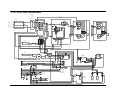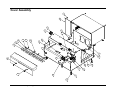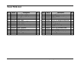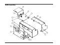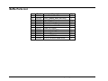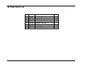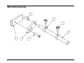
1
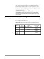
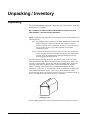
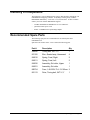
Users Manual LOKPRINT II Industrial Apparel Label Station Operation / Maintenance And Parts List AVERY DENNISON Manual Edition 4.0 9 June 2010 Manual Part Number 561398 This page intentionally left blank ii • Users Manual LOKPRINT™ II Contents Scope 5 Introduction................................................................................................................................ 5 Safety Issues / Warnings 5 Caution....................................................................................................................................... 5 Heaters......................................................................................................................... 5 Feed Roller .................................................................................................................. 5 Warranty Information 6 Location / Power Requirements 8 Location of LOKPRINT™ II System ........................................................................................ 8 Recommended Work Station Layout........................................................................... 8 AC Power Line .......................................................................................................................... 8 LOKPRINT™ II Main Line Protection....................................................................... 9 LOKPRINT™ II Internal Fuse Configuration ........................................................................... 9 Branch Circuit Protection ............................................................................................ 9 Unpacking / Inventory 10 Unpacking................................................................................................................................ 10 Inventory of Components......................................................................................................... 11 Recommended Spare Parts ...................................................................................................... 11 LOKPRINT™ II Assembly 12 Installation Setup Procedure .................................................................................................... 12 System Interface Cable Connections........................................................................................ 13 Installing the Power Cord ........................................................................................................ 13 Product Description 14 Theory of Operation................................................................................................................. 14 Description of Operation ......................................................................................................... 14 Hands free operation.................................................................................................. 14 Interlocks ................................................................................................................... 14 LOKPRINT™ II Specification ................................................................................................ 15 LOKPRINT™ II Operation / Adjustments 16 Jam Sensor................................................................................................................. 16 Ventilation ................................................................................................................. 17 Feed Roller ................................................................................................................ 18 Web Threading ........................................................................................................................ 18 Heat Chamber Care.................................................................................................................. 19 Feed Roller Care ...................................................................................................................... 19 Users Manual LOKPRINT™ II • 3 Lamp Replacement Procedure 20 Drive Cable Replacement Procedure 22 Installing the Drive Cable at the Capstan .................................................................................22 Troubleshooting 23 Interlock Trouble Shooting Guide ...........................................................................................24 Electrical Schematic 27 115 / 230 Volt Schematic.........................................................................................................28 Mechanical Assembly Drawings 29 Cover Assembly.......................................................................................................................30 Cover Parts List........................................................................................................................31 Baffle Assembly.......................................................................................................................32 Baffle Parts List .......................................................................................................................33 Air Filter Assembly..................................................................................................................34 Air Filter Parts List ..................................................................................................................35 Web Guide Assembly ..............................................................................................................36 Web Guide Parts List ...............................................................................................................37 Drive Assembly........................................................................................................................38 Drive Parts List ........................................................................................................................39 Feed Assembly.........................................................................................................................40 Feed Parts List .........................................................................................................................41 Controller Assembly ................................................................................................................42 Controller Parts List.................................................................................................................43 Heat Chamber Assembly..........................................................................................................44 Heat Chamber Parts List ..........................................................................................................45 Slide Mechanism Assembly .....................................................................................................46 Slide Mechanism Parts List......................................................................................................47 Cable Routing Diagram............................................................................................................48 Home Sensor Assembly ...........................................................................................................50 Home Sensor Parts List............................................................................................................51 4 • Users Manual LOKPRINT™ II Scope Introduction This user manual was arranged for the person who is going to operate the system. The information is arranged in the order that is needed to install, and then operate the system. It starts with general information, then to unpacking the carton, setup, installing the supplies, machine operation, and then finally care and maintenance. We at AVERY DENNISON hope that you will come to appreciate the efforts and quality that have gone into producing your AVERY DENNISON LOKPRINT™ II System and wish to remind you that you are our number one priority. We welcome any constructive comments or criticisms so that we may continue to offer you the best products in the industry for years to come. Safety Issues / Warnings Caution This system has some pinch points and hot surfaces. All of these areas have been well guarded and it is recommended that the safety features of this system are never altered or defeated. Heaters The heat chamber has been designed to prevent the operator from coming into contact with areas that will cause burns during normal operation. Some surfaces are very warm to the touch. The IR lamps and internal lamp guards are extremely hot. Extra care should be taken when threading the machine while the machine is turned on. Any maintenance or cleaning should be done after the machine has been turned off and allowed to cool. Feed Roller The feed rollers will absorb heat from the web as the machine runs. These rollers have a self-closing cover to avoid contact during operation. The feed system is also equipped with an operator knob to advance the fabric forward and backwards as needed to avoid touching the hot rollers. CAUTION: TURN OFF THE POWER AND ALLOW THE MACHINE TO COOL BEFORE CLEANING. Users Manual LOKPRINT™ II Scope • 5 Warranty Information Warranty Policy Avery Dennison Retail Information Systems, In-Plant Printing Solutions provides the following warranty policy. Scope Warranties against defects from workmanship for equipment and parts manufactured and sold from Sayre, PA. Includes time and material except as otherwise noted below. Time − − − New equipment and parts: 6 months Refurbished equipment and parts: 90 days Warranty period starts when equipment ships from selling location. General Conditions Avery Dennison extends warranty coverage under the following conditions. − Equipment and parts will perform within published specifications. Promised or implied statements by any Avery Dennison employee or representative will not be deemed to vary the terms of the warranty. − Equipment and parts must be installed and operated according to recommended procedures and operating conditions. − Consumable elements are not covered. Consumable elements are those that show normal wear from typical equipment usage including, without limitation, printheads, knives, rollers in contact with the web, and sonic units. Avery Dennison reserves the right to determine which elements are defined as “consumable.” − No customer maintenance may be performed except as directed by qualified Avery Dennison personnel. − Equipment and parts damaged by negligence or abuse are not covered. − Avery Dennison US reserves the right in its sole discretion to incorporate any modifications or improvements in the machine system and machine specifications which it considers necessary but does not assume any obligation to make said changes in equipment previously sold. Equipment Purchased In US and Shipped In US − Avery Dennison US covers warranty for equipment and parts installed and operated in the Americas (United States, Canada, Mexico, Central America, Caribbean Region, and South America excluding Brazil). − Outside the US, the local Avery Dennison office is responsible for equipment and parts warranty. Customers must ensure coverage during machine purchase. 6 • Warranty Information Users Manual LOKPRINT™ II − Equipment purchased and exported to regions outside local Avery Dennison office coverage are not covered by warranty. The purchasing agent must acquire a service contract from the Avery Dennison office where the equipment or parts are operated to ensure machine coverage. For example, if an agent purchases a printer in the US, exports to Brazil, and then needs warranty coverage, Avery Dennison Brazil has no obligation to provide warranty coverage. The agent must purchase services from Avery Dennison Brazil. THE WARRANTIES PROVIDED HEREIN ARE EXCLUSIVE AND ARE IN LIEU OF ANY IMPLIED WARRANTY OF MERCHANTABILITY, FITNESS FOR A PARTICULAR PURPOSE OR OTHER WARRANTY OF QUALITY OR PERFORMANCE, WHETHER EXPRESS OR IMPLIED. EXCEPT THE WARRANTY OF TITLE, IN NO EVENT SHALL AVERY DENNISON BE LIABLE FOR ANY INDIRECT, INCIDENTAL OR CONSEQUENTIAL DAMAGES, EVEN IF AVERY DENNISON HAS BEEN ADVISED OF THE POSSIBILITY OF SUCH DAMAGES. Service When ordering machines and supplies in the U.S.A., reference all correspondence to the address below. AVERY DENNISON Corporation One Wilcox Street Sayre, PA 18840 Call: 1-800-967-2927 or (570) 888-6641 Fax: (570) 888-5230 For spare parts, requests for service or technical support, contact AVERY DENNISON Corporation One Wilcox Street Sayre, PA 18840 Call: 1-800-967-2927 or (570) 888-6641 Fax: (570) 888-5230 For parts and service in other countries, please contact your local AVERY DENNISON supplier. Users Manual LOKPRINT™ II Warranty Information • 7 Location / Power Requirements Location of LOKPRINT™ II System Recommended Work Station Layout. The LOKPRINT™ II requires a workstation with a minimum worktable of 30” (76.2cm) deep x 96” (243.8cm) long x 30” high (adjustable height may be desired depending on if the operator will be standing or seating). The worktable does not include a space for the computer. The table must be capable of supporting 300 Lbs. (136.1Kg). The LOKPRINT™ II should be installed with the alignment template included to ensure the fabric tracks properly from the printer into the LOKPRINT™ II. Locate the Finishing Station or Cold Knife Cutter as close to the exit of the LOKPRINT™ II as possible without restricting its dancer arm travel. AC Power Line The LOKPRINT™ II requires an electrical service of 20A @ 115V or 10A @ 230V and must be purchased as a 115 or 230 volt electrical configuration. Check the machine’s serial number plate to make sure the machine is the desired electrical line voltage. Power consumption is 18 amps @ 115 volts and 9 amps @ 230 volt. Connect the power cord to a grounded 115 or 230 volt AC electric outlet of sufficient 8 • Location / Power Requirements Users Manual LOKPRINT™ II power. Because of the higher current draw of the LOKPRINT™ II, the printer / Finishing Station or Cold Knife should be on a separate electrical service of 15A. Refer to the Printer and Finishing Station or Cold Knife serial number plates for their line requirements. Please check with your local electrical code and have the system wired by a qualified electrician. LOKPRINT™ II Main Line Protection The LOKPRINT™ II main AC power switch also serves as a resettable circuit breaker. The 115V machine incorporates a 20A breaker while the 230V machine uses a 10A breaker. LOKPRINT™ II Internal Fuse Configuration Branch Circuit Protection Both controllers and the feed motor drive circuit have a 5x 20mm fuse as per the following chart. Device Users Manual LOKPRINT™ II U1 Fuse Designator F3 AVERY DENNISON Part # 990754 U2 F4 990754 Web Feed Motor F6 990915 115 VAC & 230VAC 1.0A 250V FA 5x20mm 1.0A 250V FA 5x20mm 1.6A 250V TL 5x20mm Location / Power Requirements • 9 Unpacking / Inventory Unpacking The AVERY DENNISON equipment is shipped in a large cardboard box, which may be difficult to move by hand. DO NOT REMOVE THE MACHINE FROM THE BOX OR UNPACK IN THE SHIPPING / RECEIVING DEPARTMENT. NOTE: Unpacking in the shipping/receiving department is not recommended for the following reasons. First: The cardboard carton in which your AVERY DENNISON equipment was shipped allows the machine to be moved with a forklift, forkcart or handcart. Because of the weight of the machine, it is easier and safer to use one of these devices to move the equipment to its intended installation location. Second: Leaving the machine in the carton while it is being moved within your facility will help to protect the equipment during any movements to this location. Once the equipment has reached its intended location you should begin the unpacking process. Open the carton from the top. Do not cut deep into the carton, as there are items located just under the top. Remove the items located on the top insert. Remove the top insert. Lift the machine onto the table with the two banding straps. Remove the two straps and the plastic from the machine. Inspect the machine for shipping damage. If damage is discovered, contact AVERY DENNISON for further instructions - in the U.S.A. at (570) 888-6641. In other countries please contact your local AVERY DENNISON supplier. Once you are satisfied that there was no obvious shipping damage, the machine can now be moved to its intended location. In some cases, a double box has been used to ship your machine. Shipping Carton. Save the shipping materials to relocate the equipment or return to factory for service. 10 • Unpacking / Inventory Users Manual LOKPRINT™ II Inventory of Components The following is a list of additional parts (pieces) that should be included in your LOKPRINT™ II shipping container. If anything is missing notify AVERY DENNISON immediately – in the U.S.A. at (570) 888-6641. In other countries contact your local AVERY DENNISON supplier. – AVERY DENNISON LOKPRINT™ II “User’s Manual”. – Quick-disconnect power cord. – Printer / LOKPRINT™ II positioning template. Recommended Spare Parts The following spare parts are recommended for each facility that has a LOKPRINT™ II Spare Parts Kit 560010 120V / 230V contains the following parts. Users Manual LOKPRINT™ II Part # Description Qty 224045 Timing belt 1/5P 72T 1 561120 Elec, Quartz lamp, Harnessed 4 564010 Spring, Feed, Right 2 564011 Spring, Feed, Left 2 564030 Assembly, Grit roller, Upper 1 564031 Assembly, Grit roller 1 990754 Fuse, 1.0A 250V F.A. 5 X 20mm 2 991113 Drive, Timing belt, 54T X ¼” 1 Unpacking / Inventory • 11 LOKPRINT™ II Assembly Installation Setup Procedure 1) Assemble the system components and connect all the interface cables between the three components. 2) Check / set the Printer TCB DIP switches for a 676 with stacker jam disabled (1, 3, and 4 ON / all others OFF). 3) Power on the Printer, Lokprint II, and Finishing Station for warm up. 4) While the Lokprint II Ready light is still off close the Lokprint II and Finishing Station guards, raise the Finishing Station stacker platform, and check / enter the value for Calibrate Sensor “Stacker Not Blocked” on the 676. This value should be somewhere around “40”. Once the ready light comes on check / enter the value for “Stacker Blocked”. This value should be somewhere around “225”. 5) Load fabric and ink on the Printer, advance the fabric though the Lokprint II. 6) Once all interlocks are satisfied press the start button on the printer to clear any remaining errors, the front panel should now read “Ready For Batches / Lokprint II”. 7) Download data to the Printer, this format should include a printed sense mark for the Finishing Station to register. 8) Press start again and allow the system to run until there are sufficient printed labels to thread and register in the Finishing Station. 9) Thread the Finishing Station and align the sensor / sense mark for registration. The sense mark must be the first thing the sensor sees when you start the Finishing Station. 10) Set the Finishing Station settings on its front panel as needed for the format and start the Finishing Station in order to remove the slack between the Lokprint II and the Finishing Station. The Speed adjustment should be set to provide constant tension on the fabric between the Lokprint II and the Finishing Station with the least Finishing Station stopping and starting. 11) Start the system, while running take note of the Lokprint II oven position in relation to the oven insulation strip secured to the Plexiglas guard. The oven should fully engage the strip squarely from one end of the oven to the other. The oven position is controlled by a C sensor sensing a metal flag bolted to the back of the outer oven. Check / adjust the sensor position as needed to cause the oven to travel to the desired position. The guard insulator strip can be adjusted up or down as needed by loosening it’s mounting hardware and relocating it accordingly. The Lokprint II back cover will need to be removed to make the sensor adjustment. Do not attempt to run the system with the cover removed, as the process will over heat for lack of controlled airflow around the oven. 12) Check / adjust both guard switch bales as needed to cause both switches to trigger only when the guard is closed. 12 • LOKPRINT™ II Assembly Users Manual LOKPRINT™ II 13) Once the oven position has been checked / adjusted - run the system and take note of the fabric position in relation to the oven as it enters the oven. Adjust the Lokprint II box forward or backwards on the bench in relation to the printer using the template / mount knob. The web position collars on the 676 are more for a reference then position. Do not use them to deflect the web, as wrinkling will occur. Do set them to the web edges after the Lokprint II position has been adjusted to cause the fabric to flow into the oven centered front to back. 14) Once the Lokprint II position has been checked / adjusted - run the system and adjust the Finishing Station on the bench forward or backwards in relation to the Lokprint II box so that the fabric flows straight into the Finishing Station’s web guides. 15) Using the CALIBRATION PROCEDURE section of IS 561301 Rev 2 or higher check / adjust U1 and U2 offsets as needed to produce and monitor the exit temperature at 400° while running stabilized. Note: Requires AVERY DENNISON Service 16) Using the SP2 ADJUSTMENT PROCEDURE section of IS 561301 Rev 2 or higher check / adjust U1 SP2 as needed to transition from idle to running without deforming the fabric or dipping in process temperature. Note: Requires AVERY DENNISON Service System Interface Cable Connections Connect both the 7 and 15 pin cable connectors located on the left side of the LOKPRINT™ II to the host printer. Connect the 7-pin cable connector located on the Finishing Station or Cold Knife to the 7-pin receptacle located on the right side of the LOKPRINT™ II. Installing the Power Cord Both the 115V and 230V machines incorporate a quick disconnect power cord. The 115V cord requires a NEMA 5-20R receptacle while the 230V cord requires a NEMA 6-15R receptacle. Install the receptacle end of the power cord in the plug on the back of the machine then insert the plug end of the cord in the appropriate wall outlet. Users Manual LOKPRINT™ II LOKPRINT™ II Assembly • 13 Product Description Theory of Operation The LOKPRINT™ II was designed to receive labels printed on both sides from a AVERY DENNISON 676 printer or one sided from a AVERY DENNISON 636 printer using dye sublimation inks. The LOKPRINT™ II dye sublimates the labels and feeds a Finishing Station for ultrasonic or cold knife cutting. The LOKPRINT™ II is equipped with four infrared (IR) quartz heating bulbs and two non-contact IR heat sensors with one PID controller controlling the process and a second monitoring the fabric temperature. The PID controller controls an SCR that regulates the energy provided to the quartz bulbs, which produces the heat. The PID control, IR sensor, SCR, and quartz bulbs are all part of an automatic, “closed loop” system to ensure fully sublimated labels. Once connected, all components of the LOKPRINT™ II act as a system, including the Printer, LOKPRINT™ II and the Finishing Station. Optimum dye sublimation occurs between the temperatures of 400° - 420° F (205° - 215.5° C) inside the heat chamber. The LOKPRINT™ II will shut the printer down if the web temperature drops below 400° F (205° C). This closed loop system approach ensures maximum sublimation and minimum label waste. Description of Operation Hands free operation Once the LOKPRINT™ II has been threaded, very little operator input is needed. As the fabric moves through the heat chamber - the PID controllers control and monitor the web temperature according to web speed. The LOKPRINT™ II is threaded with the heat chamber in a parked (back) position. When the printer’s start button is pushed, the heat chamber will move forward to the operating position that covers the web - heating it to the desired temperature. If the “stop” button on the printer is pushed or if the system shuts down automatically, the heat chamber will move back to the parked position. Interlocks During operation, the LOKPRINT™ II will shut down the system automatically, if one or more of the following conditions exist. See the Printer and or Finishing Station manuals for their interlocks. 14 • Product Description (1) Power lost to the LOKPRINT™ II. (2) LOKPRINT™ II power switchable circuit breaker exceeds safe current or temperature levels. (3) Oven didn’t reach the operating position in time at startup. (4) No web in web sensor. (5) Heat chamber thermostat temperature exceeds safe limit. Users Manual LOKPRINT™ II (6) Web under temperature alarm. (7) Oven over temperature alarm. (8) Guard open. The recommended room temperature for the system is 60°F (15.5°C) to 90°F (32.2°C). If a cooling system is required it should not be pointed directly at the system to create drafts that could affect the sublimation process. LOKPRINT™ II Specification Sublimation method: Non-contact Narrow polyester web Dye sublimation thermal transfer inks Web speed: Speed – 5 IPS - (127mm/second) Web Size: Min: 1.062" (27mm) Max: 2.0" (50.8mm) Feed length: No restrictions on the LOKPRINT™ II station Cutting: No cutter included in LOKPRINT™ II station Interface: AVERY DENNISON 636LKP (one sided) AVERY DENNISON 676LKP (2 over 0, 1 over 1 and 2 over 1) thermal printers Finishing method interface: SS Finisher (ultra sonic cutter with stacker) Cold knife (cutter and stacker) 12” Rewind Dimensions 13.5" (34.5cm) high x 26.5" (67.3cm) wide x 23.5" (59.7cm) deep Weight 58 Lbs. (26.3Kg.) Shipping Weight = 81 Lbs. (36.7Kg.) Electrical 115 volt system: 90-132 VAC 50-60Hz 20Amp 1 Phase. 230 volt system: 180-265 VAC 50-60Hz 10Amp 1 Phase. Temperature 60°F (15.5°C) to 90°F (32.2°C) Humidity 5% to 90% non-condensing Patent pending Users Manual LOKPRINT™ II Product Description • 15 LOKPRINT™ II Operation / Adjustments JAM SENSOR Jam Sensor The jam sensor (illustrated with the bridge removed) is looking for the presence of the fabric for the printer to start and continue to operate. If the fabric in not present, the system will not start and the printer front panel will display a message “Check Stacker”. If the fabric breaks during operation and pulls out of the sensor, the system will stop and printer front panel will again display “Check Stacker”. If the web sags more than the feed can take up before the heat chamber moves to the run position, the web may be pushed out of the jam sensor and stop the system. 16 • LOKPRINT™ II Operation / Adjustments Users Manual LOKPRINT™ II VAPOR FILTER SNAP ON COVER Ventilation The LOKPRINT™ II is equipped with a ventilation system comprising of two fans with carbon filters and multiple internal machine compartments / components. One filter is used to reduce the odors that are exhausted from the heat chamber while the other is used to filter the ambient air drawn in to cool the electronics compartment. Vapors created during the sublimation process have an odor and may be seen as smoke escaping from the heat chamber area. If there is an unusually high amount of odor or visual smoke escaping near the front of the machine - check the filter(s) on the back of the machine. Make sure they are in place and clean. The filters are held in place with a snap on cover for quick and easy replacement. The exhaust fan’s filter (on the right as viewed from the rear of the machine) will normally need to be turned over after every 2 rolls of ink and replaced after approximately 4 rolls of ink. At the time of replacement it is recommended to move the intake fan’s filter to the exhaust fan and install a new filter on the intake fan. This rotation procedure will insure that both filters are kept at peak performance. As the system pulls fresh air in the front of the heat chamber and exhausts it out the filter - it also cools the outer surfaces of the machine so they are safe to the touch. These surfaces will be warm to the touch, but will not cause burns. It is extremely important to keep the Plexiglas guard closed at all times during operation except for threading the fabric. The airflow management and heat chamber control systems have both been designed to operate with the guard closed and all the covers in place. Attempting to operate the system with any guard or cover altered or missing will disrupt the control strategies and adversely affect the fabric temperature. Users Manual LOKPRINT™ II LOKPRINT™ II Operation / Adjustments • 17 Feed Roller The feed roller has two torsion springs that supply even tension for tracking. If the fabric fails to track properly through printer, check to see if one of the springs have come loose, broken or been stretched out of shape. The feed is equipped with a hand knob used to thread the machine. This knob should turn freely with very little resistance. If resistance occurs, check to see if the roller bearings need to be greased / replaced. Use standard multi purpose grease to lubricate the bearings. To lubricate the bearings - the assembly will need to be disassembled, cleaned and repacked with grease. Do not use contact cleaners to clean the bearings, as this will destroy the needle bearings. Web Threading Feed the fabric through the AVERY DENNISON 676 or 636 printer (see the AVERY DENNISON 676 or 636 manual for threading instructions), then through the LOKPRINT™ II and on through the Finishing Station or Cold Knife Cutter. Tension the web with the feed knob to remove excess slack between the printer feed rollers and the LOKPRINT™ II feed rollers. The system will further tension the web at the start of printing, but may not take out excessive web sag. TENSION WEB ROTATE AVERY DENNISON LOKPRINT™ II 18 • LOKPRINT™ II Operation / Adjustments Users Manual LOKPRINT™ II INCORRECT WEB TENSION CORRECT WEB TENSION Heat Chamber Care In the unlikely event that the fabric touches the bulbs - it will melt onto them and / or the inner oven. Remove as many of the un-melted pieces as possible without touching the bulbs. DO NOT attempt to scrape melted fabric from the bulbs. Any remaining fabric residue will burn off, much like a self-cleaning oven. Simply re-thread a fresh section of fabric and continue printing. CAUTION: DO NOT try to scrape or chip melted fabric off the IR lamps. This could permanently damage the IR lamp. You will notice an increased amount of smoke in the heat chamber as the bulbs burn off the melted web fabric. This is normal. Feed Roller Care The feed rollers will pick up the ink dye during normal operation. The rollers should be cleaned after every two rolls of ink. The rollers can be cleaned with alcohol and a nylon bristle toothbrush. The rollers have a Teflon® coating that can be damaged if cleaned with a wire brush, making it very difficult to clean once the coating is worn off. The alcohol used for cleaning should have an alcohol content of 70% or higher and can be purchased from your local drug store. Users Manual LOKPRINT™ II LOKPRINT™ II Operation / Adjustments • 19 Lamp Replacement Procedure 1. Remove rear cover from machine chassis. Disconnect the lamp wires from the two terminal blocks located on the back of the lamp oven for the defective lamp(s). 2. At front of the machine, open clear, plastic oven guard and move lamp oven forward. Oven top is hinged. Swing oven top upward to expose lamp guards and lamps. 3. Unscrew lamp holders from lamp guards and remove the defective lamp(s) and lamp holders. Replace old or defective lamp(s). 4. Re-assemble lamp holders and lamps to lamp guards. Do not over tighten the lamp holders and crack the mounts. Feed lamp wires through wire grommets in back of oven. Ensure upper wires go through upper grommets and lower wires go through lower grommets. Re-connect lamp wires to the terminal blocks located on the back of the lamp oven. 5. Close top to lamp oven. Re-attach rear cover to main chassis. Close clear plastic oven guard. OVEN TOP LAMP WIRE LAMP HOLDER LAMP LAMP GUARD 20 • Lamp Replacement Procedure Users Manual LOKPRINT™ II LAMP HOLDER TERMINAL BLOCK UPPER WIRE GROMMET OVEN TOP BACK OF OVEN TERMINAL BLOCK LOWER WIRE GROMMET Users Manual LOKPRINT™ II Lamp Replacement Procedure • 21 Drive Cable Replacement Procedure Installing the Drive Cable at the Capstan BOTTOM VIEW BACK OF MACHINE STOP SLEEVE CABLE RIGHT SIDE 3 4 CABLE LEFT SIDE 1 2 STOP SLEEVE GROOVE CAPSTAN FRONT OF MACHINE 1: Feed the drive cable in from left hand side and wind around the Capstan five times, starting from the top and working down to the bottom. 2: Wrap the Drive Cable into the Stop Sleeve Groove so that the Stop Sleeve fits. 3: Once the Drive Cable exits the Stop Sleeve Groove, wrap the Drive Cable around the Capstan again. 4: Continue feeding the Drive Cable forward to the right side and around the Drive Cable pulleys on the machine. 22 • Drive Cable Replacement Procedure Users Manual LOKPRINT™ II Troubleshooting Problem Web will not advance Probable Cause Corrective Action 1) Insufficient feed pressure. 1) 2) 3) 4) 2) Defective feed component. 1) 2) 3) 4) 5) Web will not sublimate completely. 1) IR lamp(s) out 2) 3) 4) 5) Smoke coming from the front of Heat Chamber. Defective IR sensor Defective sensor controller Blocked filters Web is not tracking through the middle of the heat chamber. 1) Blocked filter 1) 1) 1) 1) 2) Fan not operational 1) Check blown fuse. 2) Replace defective fan. 1) Stop system and allow the build up to burn off. 3) Web broken or fallen on IR lamps causing excessive build up on lamps Users Manual LOKPRINT™ II 6) 1) 2) 3) Check for broken spring. Spring is off pressure mount pin. Clean ink build up from grit rollers. Check for thread fiber in feed roller bearings. Check for loose or broken feed timing belt. Check for loose setscrews on feed motor or grit roller driven shaft. Check for worn bearings. Worn feed or pressure grit rollers. Rheostat out of adjustment – Call for service support Defective feed motor Replace blown lamp(s). Inspect wire leads from lamps Check for loose terminal block connection. Replace Replace Replace filters Move the LOKPRINT™ II so the web tracks in the center of the heat lamps. Replace filter(s). 1) Troubleshooting • 23 Interlock Trouble Shooting Guide The following is a list of Lokprint II problems along with possible causes / remedies of each that will stop the host printer with a check stacker error: Problem No lights on / in Lokprint II Check Stacker error cannot be cleared. System will not start. Lokprint II READY light is not on. Check Stacker error cannot be cleared. System will not start. Probable Cause Power switch position. Toggle power switch on back of Lokprint II box. Power switch over current trip. Confirm power switch rating matches machine line voltage. Check lamp-wiring matches machine line voltage. Check SCR Controller strapping matches machine line voltage. Plant electrician. Wait 8 minutes after the C light on the Fuji turns on. Outlet / power fault. Insufficient time since the Fuji sensed the top of the inner oven at 400°. Ready light bulb fault. Wiring error / fault. U1 Controller programming error. U1 offset error. U2 Monitor programming error. U2 offset error. SP / SP2 switch bale misalignment or fault. Oven lamp wiring error / fault. U2 Sensor fault. U2 Monitor fault. U1 Sensor fault. U1 Controller fault. 24 • Troubleshooting Corrective Action Evaluate / replace bulb as needed. Confirm proper connection of 7-pin connector between the Lokprint II and the 676. Confirm wiring of all component(s) that were replaced. AVERY DENNISON service to confirm / reprogram as needed. AVERY DENNISON service to confirm / set exit temperature as needed. AVERY DENNISON service to confirm / reprogram as needed. AVERY DENNISON service to confirm / set offset as needed. Adjust / evaluate / replace oven position switch. Check lamp wiring matches machine line voltage / evaluate / replace as needed. Evaluate / replace sensor, requires AVERY DENNISON service to confirm / set exit temperature as needed. Evaluate / replace U2, requires AVERY DENNISON service to confirm / set exit temperature as needed. Evaluate / replace sensor, requires AVERY DENNISON service to confirm / set exit temperature as needed. Evaluate / replace U1, requires AVERY DENNISON service to confirm / set exit temperature as needed. Users Manual LOKPRINT™ II Problem Lokprint II READY light is on. Check Stacker error can be cleared. Oven travels out or attempts to travel out and immediately retracts. Probable Cause Oven obstacle. Remove / adjust obstacle so that oven travels freely. Oven to guard insulation strip misalignment. Oven out sensor misadjust / wiring error / fault. Oven drive line fault, mechanical or electrical. Adjust insulation strip for full oven engagement without interference. Adjust sensor for proper oven position / evaluate / replace sensor. Evaluate the drive line for mechanical binds / problems. Confirm proper connection of 15-pin connector between the Lokprint II and the 676. Thread the web through the Lokprint II Center the web in the Lokprint II web sensor. Reinstall the IR shield. Evaluate / replace the web sensor. AVERY DENNISON service to confirm / set SP2 as needed. No web. Web not centered in web sensor. System stops during batch Lokprint II READY light goes out. Check Stacker error cannot be cleared for 8 minutes. System will not start. Web sensor IR shield missing. Web sensor / wiring fault. SP2 Misadjusted. U1 Controller programming error. U1 offset error. U2 Monitor programming error. U2 offset error. Oven lamp wiring error / fault. U1 Sensor fault. U2 Sensor fault. U1 Controller fault. U2 Monitor fault. Users Manual LOKPRINT™ II Corrective Action AVERY DENNISON service to confirm / reprogram as needed. AVERY DENNISON service to confirm / set exit temperature as needed. AVERY DENNISON service to confirm / reprogram as needed. AVERY DENNISON service to confirm / set offset as needed. Evaluate the four lamps / wiring / replace as needed. Evaluate / replace sensor, requires AVERY DENNISON service to confirm / set exit temperature as needed. Evaluate / replace sensor, requires AVERY DENNISON service to confirm / set exit temperature as needed. Evaluate / replace U1, requires AVERY DENNISON service to confirm / set exit temperature as needed. Evaluate / replace U2, requires AVERY DENNISON service to confirm / set exit temperature as needed. Troubleshooting • 25 Problem Lokprint II READY light is on. Check Stacker error can not be cleared. System will not start. Finishing Station displays Close Guard. U1 readout > 800°. Probable Cause Lokprint II guard open. Close guard. Finishing Station stacker platform at bottom of its travel. Finishing Station guard open. Remove labels and raise platform. U1 Sensor misalignment. AVERY DENNISON service to realign sensor. AVERY DENNISON service to confirm / reprogram as needed. Evaluate / replace IR sensor, requires AVERY DENNISON service to confirm / set exit temperature as needed. Evaluate / replace U1, requires AVERY DENNISON service to confirm / set exit temperature as needed. Evaluate / replace SCR. Adjust the oven out sensor mount bracket position as needed. U1 Controller programming error. U1 Sensor fault. U1 Controller fault. Lokprint II READY light is on. Oven travels out or attempts to travel out and immediately retracts. Check stacker error can be cleared. Lokprint II Ready light is not on. Check Stacker error can be cleared. System starts but does not pull fabric though the oven. System stops during batch Lokprint II READY light is on. Check Stacker error can be cleared. Finishing Station displays Align Stock SCR fault. Oven out sensor misadjustment. Close guard. Oven to guard insulation strip misalignment. Guard switch bale(s) misadjusted. 7 pin connector between the Lokprint II and 676 partially or completely disconnected. Adjust the guard insulator strip as needed. Finishing Station sensor misadjusted. Align sensor and fabric so that the sensor mark is the first thing the sensor will see at restart. Adjust the sensor sensitivity to respond to the sense mark on the fabric. Set the cut length on the Finishing Station front panel to match the distance between the sense marks on the fabric after the Lokprint II oven. AVERY DENNISON service to confirm / set exit temperature as needed. Finishing Station cut length misadjusted. Lokprint II exit temperature too high. 26 • Troubleshooting Corrective Action Adjust the switch bale(s) as needed. Reinsert the 7-pin connector. Users Manual LOKPRINT™ II Electrical Schematic Users Manual LOKPRINT™ II Electrical Schematic • 27 115 / 230 Volt Schematic SEE NOTES 5, 6, 7, 8, & 9 115V 20A 990762 230V 10A 990764 HARNESSED SCR CONTROLLER 561106 SWITCHABLE CIRCUIT BREAKER AC ENTRY 990953 Y Y/W TB1 SCR1 R1 LINE TB4 R1 LINE CORD 561129 115V 1 GROUND CONN 7, 6-7 TB3 R2 SCR2 230V 2 NC R3 R1 C1 F5 1 LINE CORD 561130 230V TB4 R1 CONN 7, 1-5 NEUTRAL SEE NOTES 5, 6, 7, 8, & 9 CONN 4 SEE NOTES 5, 6, 7, 8, & 9 CONN 7, 6-7 990957 TH1 R2 6 T1 2 R1W R R2 990957 TH1 6 4 R3 R3 TB3 3 R4 MOUNT WITH GROUND DOWN R4 3 NC 1 115V R4 5 4 QUARTZ BULB 561120 4X QUARTZ BULB 561120 4X 0 TB5 7 TB5 7 R1 3 R1 TB3 2 TB3 5 NC R2 R2 CONTROL BOARD IR SENSOR 561147 1 RIGHT RED 7 1 2 2 8 1 3 3 9 1 4 4 1 0 1 5 5 5 6 7 8 9 RED 1 1 6 LEFT 10 BLACK CONTROLLER U1 561138 230V SEE NOTES 5, 6, 7, 8, & 9 115V SEE NOTES 5, 6, 7, 8, & 9 82K CONN 2 TC1 1 F3 2 NO OVEN POSITION SWITCH 990861 NC COMM CONN 2 IR SENSOR 561110 LEFT - RED 2 3 + MONITOR 561148 RIGHT + RL2 990890 4 1 TC2 RL1 990890 U2 NC NO F4 5 8 NC NO NO COMM NC GUARD NO SWITCHES 191120 COMM NC 561114 HARNESSED 24V POWER SUPPLY CONN 3 COMM CONN 6 COMM L N 7 7 PIN MICRO DIN PLUG 6 7 PIN MICRO DIN RECEPTACLE 7 PIN CABLE 561125 1 2 3 4 5 6 7 RETURN 1 2 3 4 5 6 7 NO CONN 4 NC 15 PIN D SHELL PLUG 1 2 3 4 5 6 +24V G CONN 4 F6 RL3 7 8 9 10 11 RHEOSTAT 221124 SEE NOTE 10 COMM 15 PIN CABLE 561127 READY LIGHT 990978 REPLACEMENT BULB 561152 CONN 3 4.7K OVEN OUT SENSOR 371131 OVEN STEPPER MOTOR 351141 SEE NOTE 4 D1 CONN 2 CONN 2 EE PROM DR1 100 ohm 390 2.21K 0.1 mF 150 28 • Electrical Schematic FEED MOTOR 221113 CONN 8 SEE NOTE 4 CONN 3 12 13 14 15 561149 470 1W 3 CONN 4 WEB SENSOR 561133 TIME DELAY RELAY 990979 SEE NOTES 5, 6, 7, 8, & 9 1 CONN 2 Users Manual LOKPRINT™ II 561137 DC FAN ELECTRICAL MOUNT BLOWING IN 561137 DC FAN OVEN MOUNT BLOWING OUT CONN 2 Mechanical Assembly Drawings Users Manual LOKPRINT™ II Mechanical Assembly Drawings • 29 Cover Assembly 7 3 7 13 2 11 25 20 24 26 21 7 1 22 7 12 28 4 23 7 16 26 5 6 17 30 • Mechanical Assembly Drawings Users Manual LOKPRINT™ II 10 14 18 Cover Parts List Item 1 2 3 4 5 6 7 8 9 10 11 12 13 14 Part # 561203 565008 561204 561206 561205 991199 990090 990052 565032 561210 990050 565034 224051 990728 Description Cover, Chassis, Main Bracket, Mount, Pulley Cover, Chassis, Back Hinge, Feed cover Cover, Feed Bumper, Rubber 8-32 10-32 x 3/8 Button head screw 10-32 x 1/2 Cap screw Bracket, In-out oven switch Cover, Controller 8-32 x 1/4 Cap screw Bracket, Control switch Hinge, Access cover Washer, #10 lock Users Manual LOKPRINT™ II Qty 1 1 1 1 1 5 29 5 1 1 2 1 3 2 Item 15 16 17 18 19 20 21 22 23 24 25 26 27 28 Part # 561133 564019 990052 990103 990089 561221 565027 561218 990014 990230 565051 990092 561209 565050 Description Sensor, Web harness (not shown) Ass'y, Stripper 10-32 x 5/16" Socket hd cap scr 10-32 Hex nut 10-32 x 1/4" Button hd cap screw Guard, Inner baffle Baffle, Heat unit Guard, Baffle flange # 10 Flat washer 10-32 x 1/4" Shoulder screw Spacer, Baffle 10-32 x 3/4" Button hd cap screw Cover, Front, Heat unit Bracket, Rheostat Mechanical Assembly Drawings • 31 Qty 1 1 5 2 1 1 2 1 2 3 4 3 1 1 Baffle Assembly 7 6 4 1 4 3 10 11 4 5 9 4 1 8 12 9 32 • Mechanical Assembly Drawings 4 Users Manual LOKPRINT™ II Baffle Parts List Item 1 2 3 4 5 6 7 8 9 10 11 12 Users Manual LOKPRINT™ II Part # 990811 561203 561217 990066 561211 561213 561212 990984 990985 990069 990512 990089 Description Strain Relief, 5/8 x 1/2 Cover, Chassis, Main (Ref Only) Guard, Top baffle 8-32 x 1/4 Button head screw Guard, Lower baffle Guard, Horizontal baffle Guard, SCR baffle Strain relief, 1/2 x 3/8 Strain relief, 1 x 3/4 Hex nut, #8 Tie wrap, TY534M 10-32 x 1/4 Button head screw Qty 3 1 1 16 1 1 1 1 3 1 1 2 Mechanical Assembly Drawings • 33 Air Filter Assembly 4 6 3 5 2 1 7 8 34 • Mechanical Assembly Drawings Users Manual LOKPRINT™ II Air Filter Parts List Item 1 2 3 4 5 6 7 8 Users Manual LOKPRINT™ II Part # 561137 990069 991198 991196 991196 565023 561140 990052 Description Fan, Exhaust Hex nut, 8-32 8-32 x 3/4 Flat head cap screw Assembly, Fan filter Assembly, Fan filter Filter, Lokprint Fan, Finger guard 8-32 x 1/2 Cap screw Qty 2 16 8 2 2 2 2 8 Mechanical Assembly Drawings • 35 Web Guide Assembly 6 3 4 2 5 1 36 • Mechanical Assembly Drawings 7 Users Manual LOKPRINT™ II Web Guide Parts List Item 1 2 3 4 5 6 7 Users Manual LOKPRINT™ II Part # 353004 194020 990374 990484 565021 990133 990123 Description Roller mount Web turn shaft 1/2 Collar 1/4-20 x 1/2 Nylon slotted screw Bracket, Tie bar 1/4-20 x 3/4 Flat head screw 1/4-20 x 1 Cap screw Qty 1 1 2 2 1 1 1 Mechanical Assembly Drawings • 37 Drive Assembly 21 22 11 19 20 16 18 13 6 4 12 12 17 13 15 10 5 2 12 3 15 1 8 14 9 7 38 • Mechanical Assembly Drawings Users Manual LOKPRINT™ II Drive Parts List Item 1 2 3 4 5 6 7 8 9 10 11 12 13 14 15 16 17 18 19 20 21 22 Users Manual LOKPRINT™ II Part # 564033 564005 564031 564034 564035 564030 105023 990058 990456 564010 564011 991194 990167 564013 999108 564016 990080 564032 378064 989983 378060 990019 Description Assembly, Mount plate, Front Bracket, Base, Feed Assembly, Grit roller Assembly, Pressure arm, Rear Assembly, Pressure arm, Front Assembly, Grit roller, Upper Knob, Impression adjust 8-32 x 1/4 Knurled cup point 8-32 x 1/2 Flat hd cap screw Spring, Feed right Spring, Feed left 1/4 x 1 shoulder bolt 10-32 Washer, 1/4 SAE Shaft, Knob adapter Bushing, 3/8 x 1/2 x 1/4 Bracket, Jam sensor mount 10-32 x 3/8" Socket hd cap screw Ass'y, Mount plate rear Bracket, Jam sensor 4-40 x 1/4 Button head screw Guard strip, Jam sensor 6-32 x 1/4 Button head screw Qty 1 1 1 1 1 1 1 1 4 1 1 4 2 1 2 1 2 1 1 2 2 4 Mechanical Assembly Drawings • 39 Feed Assembly 2 12 8 4 11 6 10 9 7 6 10 3 1 5 40 • Mechanical Assembly Drawings Users Manual LOKPRINT™ II Feed Parts List Item 1 2 3 4 5 6 7 8 9 10 11 12 Users Manual LOKPRINT™ II Part # 221113 562001 562002 991113 990029 990102 224067 990095 990756 990080 564021 564090 Description Motor, Feed / Deflect harnessed Sprocket, 30T Timing Sprocket, 10T Timing Drive, Timing belt, 54T x 1/4 6-32 x 1/4 Flat head screw Washer, #10 SAE Bracket, Motor mount 10-32 x 3/8 Set screw 6-32 x 3/16 Set screw 10-32 x 3/8 Cap screw Bracket, Feed Ass'y, Feed, 2 Sided LKP Qty 1 1 1 1 4 6 1 2 1 6 1 1 Mechanical Assembly Drawings • 41 Controller Assembly 2 4 1 3 42 • Mechanical Assembly Drawings Users Manual LOKPRINT™ II Controller Parts List Item 1 2 3 4 Users Manual LOKPRINT™ II Part # 561138 564017 561148 990090 Description Controller, Chromalox, Programmed Bracket, Controller Controller, Fuji, Programmed 10-32 x 3/8 Button head screw Qty 1 1 1 2 Mechanical Assembly Drawings • 43 Heat Chamber Assembly 13 19 15 2 7 9 14 5 10 11 26 6 24 23 4 17 21 6 25 16 22 20 5 18 3 13 1 12 2 8 29 27 28 29 44 • Mechanical Assembly Drawings Users Manual LOKPRINT™ II Heat Chamber Parts List Item 1 2 3 4 5 6 7 8 9 10 11 12 13 14 15 Part No. 565002 565004 561201 561202 990052 990079 565016 990957 990019 561120 990728 565020 990089 565030 565029 Description COVER, LAMP GUARD BRACKET, MOUNT, GUARD COVER, GUARD,LAMP LOWER COVER, GUARD,LAMP, UPPER 8-32 X ½ SOCKET HD CAP SCR 10-32 X 1/4 CAP SCREW BRACKET, FLAG, SENSOR SENSOR, 250 D, 25A THERMOSTAT 6-32 X 1/4 BUTTON HEAD SCREW QUARTZ LAMP HARNESSED WASHER, #10 LOCK BUSHING, WIRE 10-32 X 1/4 BUTTON HEAD SCREW HINGE, COVER, LAMP GUARD COVER, LAMP GUARD, UPPER Users Manual LOKPRINT™ II Qty. 1 4 1 1 10 4 1 1 6 4 2 8 16 1 1 Item 16 17 18 19 20 21 22 23 24 25 26 27 28 29 Part No. 565026 561215 990941 561219 565036 561144 990065 990768-1 565043 565044 181148 565058 565057 990080 Description BRACKET, MOUNT LAMP GUARD, OVEN INSULATION ELECTRICAL, TERMINAL BLOCK 2X2 GUARD, OVEN INSULATION, UPPER BRACKET, WIRE HARNESS CONNECTOR, CABLE 8-32 X 3/8 BUTTON HEAD SCREW ELECTRICAL, TERMINAL BLOCK 2X4 BRACKET, OVEN CLAMP COVER, LAMP 6-32 BUTTON HD CAP SCREW SLIDE BRACKET BRACKET, SLIDE MOUNT 10-32 x 3/8 SOCKET HD CAP SCR Mechanical Assembly Drawings • 45 Qty. 4 1 1 1 1 2 4 1 1 1 2 2 2 6 Slide Mechanism Assembly 1 5 21 21 9 7 22 26 27 1 18 1 10 6 1 22 8 15 13 24 21 4 13 18 12 11 14 15 21 14 11 23 17 20 19 4 18 1 5 3 25 28 21 16 8 46 • Mechanical Assembly Drawings Users Manual LOKPRINT™ II ________________________________________________________________________________________________________________________________ Slide Mechanism Parts List ITEM 1 2 3 4 5 6 7 8 9 10 11 12 13 14 Part No. 989977 991183 990940 990079 990090 285027 351141 565010 565009 564003 224068 561147 224073 999103 Description WASHER, #10 STAR EXTENSION SPRING (NOT SHOWN) MOUNTING SCREW FOR IR SENSOR 10-32 X 1/4 CAP SCREW 10-32 X 3/8 BUTTON HEAD SCREW LINEAR BEARING STEPPER MOTOR, HARNESSED SHAFT, SLIDE MOUNT BRACKET, MOUNT STIFFNER BRACKET, MOUNT,STEPPER MOTOR SHAFT, IDLER PULLEY ASSY, IR SENSOR, HARN. FOCUSED DRIVE, IDLER PULLEY BUSHING, 1/4 X 3/8 X 1/2 Users Manual LOKPRINT™ II Qty 12 2 4 4 4 4 1 2 1 1 4 1 4 4 ITEM 15 16 17 18 19 20 21 22 23 24 25 26 27 28 Part No. 990262 565042 991194 565033 991182 565008 990084 990081 561110 562003 564024 565095 991246 565057 Description SNAP RING, 1/4" BRACKET, CABLE 1/4 X 1 SHOULDER BOLT 10-32 BRACKET, PYROMETER 10-32 X 3/8 CAP SCREW BRACKET, MOUNT, PULLEY (REF) 10-32 X 1 CAP SCREW 10-32 X 1/2 CAP SCREW SENSOR, IR HARNESSED HEAD, DRIVE, CAPSTAN DRIVE, FEED CABLE KEEPER, BEARING BLOCK COLLAR, SNAP RING 5/8" BRACKET, SLIDE MOUNT Mechanical Assembly Drawings • 47 Qty 4 1 1 1 1 1 7 6 1 1 1 2 8 2 Cable Routing Diagram CABLE RIGHT SIDE FRONT OF MACHINE CAPSTAN CABLE LEFT SIDE STOP SLEEVE FRONT OF MACHINE TOP VIEW CABLE RIGHT SIDE WIND FROM THIS SIDE (5X) CABLE LEFT SIDE REAR VIEW 48 • Mechanical Assembly Drawings Users Manual LOKPRINT™ II This page intentionally left blank Users Manual LOKPRINT™ II Mechanical Assembly Drawings • 49 Home Sensor Assembly 50 • Mechanical Assembly Drawings Users Manual LOKPRINT™ II Home Sensor Parts List Item 1 2 3 4 5 6 7 8 Users Manual LOKPRINT™ II Part # 565015 371131 358024 989976 990015 990728 990081 990000 Description Bracket, Sensor Harness, Ink out sensor Jam sensor bracket #6 Star washer 6-32 x 1/4 Cap screw #10 Lock washer 10-32 x 1/2 Cap screw 2-56 x 1/4 Cap screw Qty 1 1 1 2 2 2 2 1 Mechanical Assembly Drawings • 51