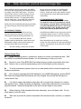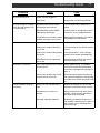
1
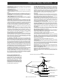
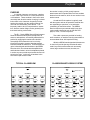
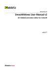
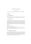
SRR60 Sound Reinforcement Receiver
Users’ Manual
TM
is a registered trademark of R.L. Drake LLC
© Copyright 2007 R.L. Drake LLC
P/N 3853203A-2007
Printed in U.S.A.
2
Caution Statements
WARNING: TO PREVENT FIRE OR
ELECTRICAL SHOCK DO NOT
EXPOSE TO RAIN OR MOISTURE
A product and cart combination should be moved with
care. Quick stops, excessive force and uneven
surfaces may cause the product and cart combination
to overturn.
RISK OF ELECTRIC SHOCK
DO NOT OPEN
The lightning flash with arrow head symbol, within an
equilateral triangle, is intended to alert the user to the
presence of uninsulated "dangerous voltage" within
the product's enclosure that may be of sufficient
magnitude to constitute a risk of electric shock to
persons.
CAUTION: TO REDUCE THE RISK OF ELECTRIC
SHOCK,
DO NOT REMOVE COVER
NO USER-SERVICEABLE PARTS INSIDE
REFER SERVICING TO QUALIFIED PERSONNEL
The exclamation point within an equilateral triangle is
intended to alert the user to the presence of important
operating and maintenance (servicing) instructions in
the literature accompanying
the product.
CAUTION
WARNING: TO REDUCE THE RISK OF FIRE OR ELECTRIC SHOCK, DO NOT EXPOSE THIS
PRODUCT TO RAIN OR MOISTURE.
DO NOT OPEN THE CABINET, REFER SERVICING TO QUALIFIED PERSONNEL ONLY.
CAUTION: TO PREVENT ELECTRIC SHOCK, DO NOT USE THIS (POLARIZED) PLUG WITH AN
EXTENSION CORD RECEPTACLE OR OTHER OUTLET UNLESS THE BLADES CAN BE
FULLY INSERTED TO PREVENT BLADE EXPOSURE.
ATTENTION: POUR PREVENIR LES CHOCS ELECTRIQUES, NE PAS UTILISER CETTE FICHE
POLARISEE AVEC UN PROLONGATEUR, UNE PRISE DE COURANT OU UNE AUTRE
SORTIE DE COURANT, SAUF SI LES LAMES PEUVENT ETRE INSEREES A FOND
SANS EN LAISSER AUCUNE PARTIE A DECOUVERT.
Important Safety Instructions
3
14. Outdoor Antenna Grounding—If an outside antenna or cable system is
connected to the product, be sure the antenna or cable system is grounded so
as to provide some protection against voltage surges and built-up static
charges. Article 810 of the National Electrical Code, ANSI/NFPA 70, provides
information with regard to proper grounding of the mast and supporting
structure, grounding of the lead-in wire to an antenna discharge unit, size of
grounding conductors, location of antenna-discharge unit, connection to
grounding electrodes, and requirements for the grounding electrode.
See Figure A.
15. Lightning—For added protection for this product during a lightning storm,
or when it is left unattended and unused for long periods of time, unplug it from
the wall outlet and disconnect the antenna or cable system. This will prevent
damage to the product due to lightning and power-line surges.
16. Power Lines—An outside antenna system should not be located in the
vicinity of overhead power lines, other electric light or power circuits, where it
can fall into such power lines or circuits. When installing an outside antenna
system, extreme care should be taken to keep from touching such power lines
or circuits as contact with them may be fatal.
17. Overloading—Do not overload wall outlets, extension cords, or integral
convenience receptacles as this can result in a risk of fire or electric shock.
18. Object and Liquid Entry—Never push objects of any kind into this product
through openings as they may touch dangerous voltage points or short-out
parts that could result in a fire or electric shock. Never spill liquid of any kind
on the product.
19. Servicing—Do not attempt to service this product yourself as opening
or removing covers may expose you to dangerous voltage or other hazards.
Refer all servicing to qualified service personnel.
20. Damage Requiring Service—Unplug this product from the wall outlet and
refer servicing to qualified service personnel under the following conditions:
a. When the power-supply cord or plug is damaged,
b. If liquid has been spilled, or objects have fallen into the product,
c. If the product has been exposed to rain or water,
d. If the product does not operate normally by following the operating
instructions. Adjust only those controls that are covered by the operating
instructions as an improper adjustment of other controls may result in damage
and will often require extensive work by a qualified technician to restore the
product to its normal operation,
e. If the product has been dropped or damaged in any way, and
f. When the product exhibits a distinct change in performance—this indicates
a need for service.
21. Replacement Parts—When replacement parts are required, be sure the
service technician has used replacement parts specified by the manufacturer
or have the same characteristics as the original part. Unauthorized substitutes
may result in fire, electric shock or other hazards.
22. Safety Check—Upon completion of any service or repairs to this product,
ask the service technician to perform safety checks to determine that the
product is in proper operating condition.
23. Wall or Ceiling Mounting—The product should be mounted to a wall or
ceiling only as recommended by the manufacturer.
24. Heat—The product should be situated away from heat sources such as
radiators, heat registers, stoves, or other products (including amplifiers) that
produce heat.
1. Read Instructions—All the safety and operating instructions should be read
before the product is operated.
2. Retain Instructions—The safety and operating instructions should be
retained for future reference.
3. Heed Warnings—All warnings on the product and in the operating
instructions should be adhered to.
4. Follow Instructions—All operating and use instructions should be followed.
5. Cleaning—Unplug this product from the wall outlet before cleaning. Do not
use liquid cleaners or aerosol cleansers. Use a damp cloth for cleaning.
6. Attachments—Do not use attachments that are not recommended by the
product manufacturer as they may cause hazards.
7. Water and Moisture—Do not use this product near water—for example,
near a bathtub, wash bowl, kitchen sink or laundry tub; in a wet basement;
or near a swimming pool; and the like.
8. Accessories—Do not place this product on an unstable cart, stand, tripod,
bracket, or table. The product may fall, causing serious injury to a child or adult,
and serious damage to the product. Use only with a cart, stand, tripod, bracket,
or table recommended by the manufacturer, or sold with the product. Any
mounting of the product should follow the manufacturer's instructions, and
should use a mounting accessory recommended by the manufacturer.
9. A product and cart combination should be moved with care. Quick stops,
excessive force, and uneven surfaces may cause the product and cart
combination to overturn.
10. Ventilation—Slots and openings in the cabinet are provided for ventilation
and to ensure reliable operation of the product and to protect it from
overheating, and these openings must not be blocked or covered. The
openings should never be blocked by placing the product on a bed, sofa, rug,
or similar surface. This product should not be placed in a built-in installation
such as bookcase or rack unless proper ventilation is provided or the
manufacturer's instructions have been adhered to.
11. Power Sources—This product should be operated only from the type of
power source indicated on the marking label. If you are not sure of the type of
power supplied to your home, consult your product dealer or local power
company. For products intended to operate from battery power, or other
sources, refer to the operating instructions.
12. Grounding or Polarization—This product may be equipped with a
polarized alternating-current line plug (a plug having one blade wider than the
other). This plug will fit into the power outlet only one way. This is a safety
feature. If you are unable to insert the plug fully into the outlet, try reversing
the plug. If the plug should still fail to fit, contact your electrician to replace
your obsolete outlet. Do not defeat the safety purpose of the polarized plug.
Alternate Warnings—If this product is equipped with a three-wire groundingtype plug, a plug having a third (grounding) pin, the plug will only fit into a
grounding-type power outlet. This is a safety feature. If you are unable to insert
the plug into the outlet, contact your electrician to replace your obsolete outlet.
Do not defeat the safety purpose of the grounding-type plug.
12 a. Mise à la terre ou Polarisation—Cet appareil est équipé avec un cordon
d'alimentation à trois fils. Il est a brancher sur une prise ayant un connecteur
a la terre. Assurez-vous que la connection a la terre ne manque pas.
13. Power-Cord Protection—Power-supply cords should be routed so that
they are not likely to be walked on or pinched by items placed upon or against
them, paying particular attention to cords at plugs, convenience receptacles,
and the point where they exit from the product.
Figure A
Example of antenna grounding as per National Electrical Code, ANSI/NFPA 70
NOTE TO CATV SYSTEM INSTALLERS:
THIS REMINDER IS PROVIDED TO CALL THE
CATV SYSTEM INSTALLER'S ATTENTION TO
ARTICLE 820 - 40 OF THE NEC THAT
PROVIDES GUIDELINES FOR PROPER
GROUNDING AND, IN PARTICULAR, SPECIFIES THAT THE CABLE GROUND SHALL BE
CONNECTED TO THE GROUNDING SYSTEM
OF THE BUILDING, AS CLOSE TO THE POINT
OF CABLE ENTRY AS PRACTICAL.
ANTENNA
LEAD IN
WIRE
GROUND CLAMP
ANTENNA
DISCHARGE UNIT
(NEC SECTION 810-20)
ELECTRIC
SERVICE
EQUIPMENT
GROUNDING CONDUCTORS
(NEC SECTION 810-21)
GROUND CLAMPS
NEC - NATIONAL ELECTRIC CODE
POWER SERVICE GROUNDING
ELECTRODE SYSTEM
(NEC ART 250, PART H)
4
Table of Contents / Specifications
TABLE OF CONTENTS
2
3
4
5
6
7
8
9
Caution Statements
Important Safety Instructions
Table of Contents / Specifications
Purpose
General Description & Installation
Additional System Components
Front Panel Controls & Connections
Rear Panel Controls & Connections
10
11
12
13
16
17
18
19
BP60 Belt Pack Controls & Connections
HHM60 Microphone Controls & Connections
Battery installation & Charging
Daily Operation
General Usage Tips
Troubleshooting Guide
Service / If you Need To Call For Help
Warranty
SPECIFICATIONS for SRR60 and related system components
SRR60 RECEIVER
Inputs:
IR Microphone Channels:
AUX Input, RCA jacks, front:
AUX Input, 3.5mm jack, front:
AUX Input, 3.5mm jack, rear:
3 Band Equalizers:
MIC Channel A:
MIC Channel B:
AUX1, AUX2 combined:
Volume Controls, front panel:
MIC, Channel A:
MIC, Channel B:
AUX 1:
AUX 2:
AUX 3:
MASTER VOLUME (speakers):
Outputs:
Speaker, rear panel terminals:
Line level AUX, front panel:
Line level AUX, rear panel:
Volume Controls,
recessed screwdriver set:
Trim for each speaker output:
Trim for each AUX Line output:
Amplifier Output Power:
Total Harmonic Distortion (THD):
5 total
2 (CH A and CH B)
1
1
1
SRR60 RECEIVER (Continued)
Receiver Power Requirement:
75 W nominal @ full output /
8 ohm speakers.
150 W during fault condition
such as shorted outputs.
3 sets
1
1
1
6
1
1
1
1
1
1
6
4 sets
1
1
6
4
2
60 W maximum @ <10%
THD (15W nominal per
speaker output)
< .5 %, 1 kHz, .01 to
10 W/ CH into 8 ohms
BP60 BELT PACK with EM60LAVALIERE MIC
Channels:
IR Subcarrier Frequencies:
Battery Current:
Battery Type:
(2 used)
HHM60 HAND HELD MICROPHONE
20 Hz to 20 kHz
IR Subcarrier Frequencies:
Safety :
FCC:
Safety certified to
ANSI/UL 60065, 7th ed.
dated 6/30/04, rev
11/20/06
CAN/CSA-C22.2 No.
60065:03 (2006)
AA, Ni-MH rechargeable,
minimum of 2000 mAH
User Adjustable - access
inside battery compartment
Receiver Frequency Response:
Contact Closure and
Audio Sensing Inputs
mA low (LO): 100 mA
mA high (HI): 160 mA
Microphone Gain:
Channels:
Speaker Muting:
CH 1 - 2.06 MHz
CH 2 - 2.56 MHz
Approx 12 - 14 hours to
charge depleted 2100 mAH
cells using supplied
charger.
8 ohms, nominal
3 (1, 2, or 3 may be
used depending on
room size and dimensions.)
2 user selectable
Charging Time:
Output Impedance, speaker outputs:
Remote IR pickup sensor inputs:
120 VAC, +/- 20 %
50/60 Hz / 150 W Max.
Battery Current:
Battery Type:
(2 used)
Charging Time:
Microphone Gain:
2 user selectable
CH 1 - 2.06 MHz
CH 2 - 2.56 MHz
mA low (LO) - 230 mA
mA high (HI) - 350 mA
AA, Ni-MH rechargeable,
minimum of 2000 mAH
Approx 12 - 14 hours to charge
depleted 2100 mAH cells using
supplied charger.
Set by factory
Part 15 B
Specifications subject to change without notice or obligation.
Purpose
PURPOSE
In a typical classroom environment, a teacher
in front of the room lectures to a room filled with 30
or 40 students. Those students in the first few rows
can easily hear what the teacher is saying, but those
further back in the classroom frequently find that
hearing the teacher over the ambient noise of the
room can be considerably more difficult. This
frequently leads to lack of comprehension, inattention, disorder, teacher fatigue, and a generally less
than ideal learning environment.
The R. L. Drake SRR60 Sound Reinforcement
Receiver and associated system microphones, IR
sensors, and speakers, successfully addresses this
problem by supplying the teacher with a lavaliere
microphone which transmits his or her voice by
infrared (IR) signals to sensors placed at strategic
locations around the classroom. These sensors pick
up the infrared signals and feed them to the SRR60
Receiver which, in turn detects and amplifies them
and feeds the teacher’s voice to loudspeakers placed
in such a way as to provide equal sound volume to all
points in the room. In this way, all students in the
room have equal access to what
TYPICAL CLASSROOM
TEACHER
5
the teacher is saying, which greatly improves
attentiveness and comprehension for those students
farthest from the teacher, which in turn results in less
teacher stress.
A hand held IR microphone is typically used
with the system and can be passed to students who
are responding to questions, or are otherwise
contributing in class discussions. The SRR60
Receiver also accepts external audio inputs from
various audio-visual aids such as CD and DVD
players, VCRs, TVs and computers.
Two audio outputs are provided for feeding
audio recorders, or assistive listening transmitters to
accommodate those with impaired hearing.
While the SRR60 was designed with classrooms
in mind, it will provide just as great a benefit when
used in any similar environment such as meeting
rooms, large conference rooms, churches, etc.
CLASSROOM WITH SRR60 SYSTEM
TEACHER
Infrared sensor
STUDENTS
GOOD LISTENING AREA
STUDENTS
Ceiling mounted loudspeakers
Infrared Sensors
GOOD LISTENING AREA
POOR LISTENING AREA
Ceiling mounted loudspeakers
6
General Description & Installation
SRR60 Sound Reinforcement Receiver Front View
SRR60 Sound Reinforcement Receiver Rear View
GENERAL DESCRIPTION
The R.L. Drake model SRR60 is a professional
quality Sound Reinforcement Receiver which
accepts audio modulated infrared (IR) signals from
up to two separate IR transmitters, such as hand
held and/or lavaliere microphones. The SRR60 can
accommodate up to three external infrared sensors,
statically placed throughout a classroom or other
similar facility, which detect the transmitted IR
microphone signals. The SRR60 demodulates these
signals, provides audio shaping by means of two,
three-band equalizers, one for each IR transmitter,
and provides up to 15 watts of audio output to each
of four external speakers placed throughout the
classroom or other facility.
The SSR60 can also accept up to three
additional audio sources for connection to audio/
visual equipment such as CD or cassette players,
VCRs, DVD players, TVs, computers, etc. An
additional three-band equalizer is provided for audio
shaping of two of the three external audio sources.
Two AUX audio outputs are also provided for
connection to assistive listening transmitters or to
audio recording devices.
When connected to an external public address
system, the SRR60 can be automatically or manually muted whenever this public address system is
active.
INSTALLATION
It is recommended that the SRR60 Sound
Reinforcement Receiver be installed by a qualified
installer. Once installed, this manual covers the
required set up and also provides instructions for the
day to day use of the system.
Additional System Components
BP60 Belt Pack & EM60 Lavaliere Mic/IR Emitter
The lavaliere microphone/IR emitter should be worn at
the collarbone level by the instructor. It captures the
wearer’s voice and sends it to the battery powered belt
pack. The belt pack uses the audio to modulate an RF
signal which, in turn, modulates an IR emitter in the
lavaliere unit. Thus, the IR emotter bathes the room
with the IR signal which is picked up by IR60 sensors
strategically placed throughout the room. It is capable
of transmitting on either of two channels so that two
microphones can be in use in the same room without
interfering with each other.
IR60 Dome Infrared Sensor
7
HHM60 Hand Held IR Microphone
The HHM60 is a battery powered hand held infrared
microphone. When turned on, it captures the users
voice and transmits it via an IR signal to IR60 sensors
mounted at various locations around the room. IR
emitters are located at the bottom end of the microphone and near the top opposite the power switch, so
it is important that at least one of these locations is
not covered when in use. The HHM60 is capable of
transmitting on either of two channels so that two
microphones can be in use in the same room without
interfering with each other.
BC60 Battery Charger for Microphones
The IR60 Dome Sensor contains six infrared sensor
diodes. Its designed to be installed at a strategic
location in a classroom, usually on the ceiling, to
receive the IR signals from the hand held and
lavaliere microphones. The output of the device is
an RF signal which is available at an “F” type
connector on the back of the unit. The output RF
signal is forwarded to the SRR60 receiver through
RG59 75 ohm coaxial cable. The SRR60 receiver
can accept input from up to three of these devices.
RMB60 Rack Mount Brackets for SRR60 Receiver
This battery charger plugs into the HHM60 or BP60
unit to charge the AA size Ni-MH batteries installed
in them. Two outputs are provided so one charger can
charge two microphones at once.
Do not attempt to charge Ni-Cd batteries, or other
rechargeable cells with less than 2000 mAH
capacity, with this unit since the charging rate
would be to high for them.
Rack mount brackets are available if it is desirable
to install the SRR60 receiver in a rack cabinet. The
SRR60 Receiver is pictured below with the brackets
installed.
L
M
+10
H
L
+10
VOLUME
M
+10
H
L
+10
VOLUME
M
+10
VOLUME
SRR60 SOUND REINFORCEMENT RECEIVER
H
+10
VOLUME
VOLUME
MASTER
VOLUME
AUX INPUTS
L
-10
CHANNEL A
-10
-10
CHANNEL B
-10
-10
AUX 1
AUX2
AUX OUTPUT
R
-10
AUX 3
AUX 1
AUX 2
LEVEL
LINE OUT
POWER
UNDER NO CIRCUMSTANCES SHOULD THIS UNIT
(OR ANY CHARGER) BE USED TO CHARGE ALKALINE BATTERIES!!
8
1
Front Panel Controls & Connections
2
3
4 5
6
7
8
1. CHANNEL A VOLUME - This control varies the
volume of audio on the “A” channel relative to audio
on the other audio input channels. The SRR60 “A”
channel receives a microphone set to CH 1.
2. CHANNEL A SIGNAL INDICATOR - This green
LED lights when a signal is being received from the
microphone set for channel 1.
3. CHANNEL A THREE BAND EQUALIZER - The
equalizer allows adjustment of the frequency response of the channel “A” audio to best suit the
instructor’s voice characteristics. The “L” slider
adjusts the bass response, the “M” slider adjusts the
midrange response, and the “H” slider adjusts the
treble response. Each slider allows a plus or minus
10 dB adjustment of its particular frequency range.
4. CHANNEL B VOLUME - This control varies the
volume of audio on the “B” channel relative to audio
on the other audio input channels. The SRR60 “B”
channel receives a microphone set to CH 2.
5. CHANNEL B SIGNAL INDICATOR - This green
LED lights when a signal is being received from the
microphone set for channel 2.
6. CHANNEL B THREE BAND EQUALIZER - The
equalizer allows adjustment of the frequency response of the channel “B” audio to best suit the
instructor’s voice characteristics. The “L” slider
adjusts the bass response, the “M” slider adjusts the
midrange response, and the “H” slider adjusts the
treble response. Each slider allows a plus or minus
10 dB adjustment of its particular frequency range.
7. AUX 1 VOLUME - This control varies the volume
of audio from the AUX 1 input relative to audio on
the other audio input channels.
8. AUX 2 VOLUME - This control varies the volume
of audio from the AUX 2 input relative to audio on
the other audio input channels.
9. AUX 1 & 2 THREE BAND EQUALIZER - The
equalizer allows adjustment of the frequency response of the AUX 1 & AUX 2 audio to best suit the
9
10
11
12
13 14
15 16
instructor’s voice characteristics. The “L” slider
adjusts the bass response, the “M” slider adjusts the
midrange response, and the “H” slider adjusts the
treble response. Each slider allows a plus or minus
10 dB adjustment of its particular frequency range.
10. AUX 3 VOLUME - This control varies the
volume of audio from the AUX 3 input relative to
audio on the other audio input channels.
11. MASTER VOLUME - The master volume
control varies the volume of all audio inputs, keeping
them in the proportion set with the Channel A,
Channel B, and AUX 1, 2 and 3 volume controls.
12. AUX 1 INPUT - The AUX 1 input connectors
accept stereo audio input from such devices as CD
players, VCR/DVD players, computers, etc. These
are RCA Phono type connectors. The white connector is for the left input and the red one is for the right
input.
13. AUX 2 INPUT - The AUX 2 input connector is a
3.5 mm female audio connector and accepts monaural audio input from external devices.
14. AUX OUTPUT LEVEL - This adjustment
controls the output level at the front panel LINE OUT
jack. The relative audio level of all of the audio
sources which were set by the other front panel
volume controls is maintained as this adjustment is
varied.
15. LINE OUTPUT - The line output jack is intended
to provide audio output for such devices as cassette
recorders, DVD recorders, computers, or assistive
listening transmitters. The audio level at this 3.5
mm female audio connector is governed by the AUX
OUTPUT LEVEL control described in 14 above.
16. POWER - The POWER switch turns the
receiver’s mains voltage supply on and off. When
power is turned on, the green LED on the switch is
illuminated.
Rear Panel Controls & Connections
1
2
3
1. POWER CORD - The power cord connects the
SRR60 Receiver to standard 120 VAC 60 Hz power.
2. FUSE - The fuse holder is in series with the AC
power line. If fuse replacement is necessary, use a
1.6 amp 250 V slo-blo fuse. Rotate the fuse holder
counterclockwise to remove the fuse when necessary.
3. SPEAKER OUTPUT CONNECTIONS - The
speaker output connector consists of 8 screw type
terminals, with a “+ “and a “-” terminal for each of
four speakers.
To connect a speaker wire, use a screw driver to
loosen the screw on the appropriate terminal, insert
the speaker wire, and tighten the screw on the
inserted wire. Make sure the insulation is stripped
from the last 1/4 inch of the wire before inserting it in
the terminal.
Each “+” and “-” pair of terminals is labeled with a
number. The number of the terminal pair corresponds with the number of one of the Speaker
Output Level controls to the right of the connector.
When attaching speaker wires, it is very important to
observe the polarity. A speaker with the wires
attached with the polarity reversed with respect to
the other speakers will produce sound which is out of
phase with the other speakers, resulting in sound
cancellation (dead spots) in various locations
throughout the room.
4. SPEAKER OUTPUT LEVEL CONTROLS These controls adjust the relative volume of the
corresponding speaker. LEVEL control 1 controls the
speaker connected to “+” and “-” terminals labeled 1,
LEVEL control 2 corresponds to terminal pair 2, etc.
These controls should be adjusted so that the sound
distribution around the room is uniform. In some
cases, it may be necessary to reduce the volume
from the speakers nearest the instructor somewhat
to avoid acoustic feedback, which can produce a
howl or squeal.
4
5
6 7
8
9
9 10 11 1 2
5. AUX OUTPUT LINE OUT CONNECTOR - The
Line Out connector is a 3.5 mm female audio
connector, and produces audio output which can be
used for audio recording devices such as cassette
recorders or computers, or for assistive listening
transmitters.
6. AUX OUTPUT LEVEL - This screwdriver
adjustable control varies the output of the AUX
OUTPUT LINE OUT connector described in “5”
above.
7. AUX 3 INPUT CONNECTOR - This is a 3.5 mm
female audio input connector which is intended for
inputting stereo audio from an external source such
as a cassette tape, CD, or DVD player, a TV, or a
computer. The audio input level for this jack is
controlled by the AUX 3 VOLUME control on the
front panel.
8. INFRARED SENSOR INPUT - These three
female “F” connectors accept input from up to three
infrared sensors placed throughout the classroom.
The actual signals fed into these connectors are 2 to
3 MHz RF signals.
9. LOGIC INPUT - Grounding the center conductor
of this RCA phono connector will mute the SRR60.
10. HOLD TIME - When the SRR60 is muted by
external audio, this screwdriver adjustable control
varies the length of time between the cessation of
external audio and the unmuting of the SRR60. The
approximate range is 1 second when fully CCW to
approximately 15 seconds when fully CW.
11. SENS - This screwdriver adjustable control
varies the audio level sensitivty at the AUDIO INPUT
terminals required to mute the SRR60 from an external audio source. The approximate range is 90 volts
when fully CCW to 5 volts when fully CW.
12. AUDIO INPUT - Audio from an external source
such as a public address system is fed to these
terminals for the purpose of muting the SRR60
whenever the external source is active. (See items
10 and 11 above.)
10
BP60 Belt Pack Controls & Connections
1
2
3
4
1. EMITTER CONNECTOR The Lavaliere Mic/IR Emitter
plugs into this connector as
shown in the photo at right.
2. POWER ON LIGHT - This
LED is illuminated green
whenever charged batteries are
installed and the POWER
switch is turned on. When
batteries are low, the color will
change to red.
3. POWER SWITCH - This switch turns battery
power on and off.
4. BATTERY CHARGE CONNECTOR - The BC60
Battery Charger plugs into this connector to charge
the installed Nickel Metal Hydride (Ni-MH) batteries.
Do not attempt to use this charger if Nickel Cadmium (Ni-Cd) batteries are installed as the charging
rate is too high for them. UNDER NO CIRCUMSTANCES SHOULD THE CHARGER BE USED IF
ALKALINE OR CARBON ZINC BATTERIES ARE
INSTALLED!
5. ADJUSTMENT TOOL - This tool nests just
above the Channel Switch (8) and Mic. Gain controls
(10), and is used to set the Power and Channel
switches and to adjust the Mic. Gain control.
6. LO HI POWER SWITCH - This switch is used to
adjust the power applied to the IR transmitter in the
Lavaliere mic/IR transmitter. Setting the switch on
LO (left) will consume less battery power but will
give somewhat less IR range. Setting the switch on
HI (right) will extend the IR range, but will cause the
batteries to discharge sooner.
5
6
7
8
9 10
7. BATTERY COMPARTMENT - The battery
compartment is designed to hold two “AA” sized
batteries. Nickel Metal Hydride (Ni-MH) batteries
should be used so that they can be recharged
without taking them out of the unit. Nickel Cadmium (Ni-Cd) batteries can be used if they are
removed for recharging using an external charging
system. Carbon zinc or alkaline batteries can be
used in a pinch, but NO ATTEMPT SHOULD BE
MADE TO RECHARGE THEM !
8. CHANNEL SWITCH - The channel switch selects
between channel 1 (A) and channel 2 (B). Units are
shipped with the switch set to channel 1 (A). If
channel 1 is selected, the CHANNEL A LED on the
SRR60 Receiver will light and the CHANNEL A
Volume and Equalizer controls will be used. If
channel 2 is selected, the SRR60 CHANNEL B
controls will be active. If two microphones are used
it is important that one of them be on channel 1 and
the other on channel 2 so that they don’t interfere
with each other.
9. CHARGE CONTACT - The battery compartment
charge contact must make electrical contact with the
Nickel Metal Hydride (Ni-MH) battery installed in this
location so that charging can occur. It will be
necessary to remove approximately 1/4 inch of
insulation from the battery installed in this location. If
this is not done, the batteries will not recharge when
the charger is plugged in.
10. MIC. GAIN - This control varies the level of
modulation of the signal that occurs when the
lavaliere wearer is speaking. Too low a setting will
result in inadequate audio output from the speakers.
Too high a setting can result in acoustic feedback
(howl) or audio distortion. The correct setting must
be determined by experimentation and may very
from one instructor to another.
HHM60 Microphone Controls & Connections
1
2
3
4
5
6
1. INFRARED TRANSMITTERS - The HHM60 has
two locations for the IR transmitters. One at the
bottom of the microphone and one near the top. It is
important to keep one of these areas uncovered
when the microphone is in use so that the IR signals
will reach the sensor.
2. BATTERY CHARGING CONNECTOR - This
connector is located on the bottom of the unit. The
BC60 Battery Charger plugs into this connector to
charge the installed Nickel Metal Hydride (Ni-MH)
batteries. Do not attempt to use this charger if
Nickel Cadmium (Ni-Cd) batteries are installed as
the charging rate is too high for them. UNDER NO
CIRCUMSTANCES SHOULD THE CHARGER BE
USED IF ALKALINE OR CARBON ZINC BATTERIES
ARE INSTALLED !
3. BATTERY COMPARTMENT SLEEVE - This
sleeve protects the batteries and microphone
adjustments. To remove it, unscrew it by rotating it
counterclockwise.
4. POWER LED - This LED lights green when
charged batteries are installed and the power switch is
turned on. The color changes to red when batteries
are low.
5. POWER SWITCH - This switch turns the microphone on and off.
6. LO HI POWER SWITCH - This switch is used to
adjust the power applied to the IR transmitters.
Setting the switch on LO (down) will consume less
battery power but will give somewhat less IR range.
2
7
11
8
9
Setting the switch on HI (up) will extend the IR
range, but will cause the batteries to discharge
sooner.
7. CHANNEL SWITCH - The channel switch selects
between CH 1 and CH 2. If CH 1 is selected, the
CHANNEL A LED on the SRR60 Receiver will light
and the CHANNEL A Volume and Equalizer controls
will be used. If CH 2 is selected, the SRR60 CHANNEL B controls will be active. The units are shipped
with the switch in the CH2 (B) position. If two
microphones are used it is important that one of
them be on CH 1 and the other on CH 2 so that they
don’t interfere with each other.
8. BATTERY COMPARTMENT - The battery
compartment is designed to hold two “AA” sized
batteries. Nickel Metal Hydride (Ni-MH) batteries
should be used so that they can be recharged
without taking them out of the unit. Nickel Cadmium (Ni-Cd) batteries can be used if they are
removed for recharging using an external charging
system. Carbon zinc or alkaline batteries can be
used in a pinch, but NO ATTEMPT SHOULD BE
MADE TO RECHARGE THEM !
9. CHARGE CONTACT - The battery compartment
charge contact must make electrical contact with the
Nickel Metal Hydride (Ni-MH) battery installed in this
location so that charging can occur. If new cells are
purchased at retail, it will be necessary to remove
approximately 1/4 inch of insulation from the battery
installed in this location. If this is not done, the
batteries will not recharge when the charger is plugged
in. Do not attempt to charge other than the specified
Ni-MH cells.
12
Battery Installation & Charging
Battery Preparation (batteries from retail source)
For both the HHM60 Hand Held Microphone, and the
BP60 Belt Pack, it will be necessary to remove
approximately 1/2 inch of insulation from the negative end of one of the two batteries which will be
installed in each unit. This must be done so that the
CHARGE CONTACTs will make contact with them.
This is shown in the following photo.
Insulation Removed from negative end
Installation in BP60 Belt Pack
Insert a “AA” size Ni-MH rechargeable battery with
the insulation removed as shown above, in the BP60
battery compartment location containing the
CHARGE CONTACT, observing the polarity as
shown below.
Installation in HHM60 Hand Held Microphone
Insert a “AA” size rechargeable battery with the
insulation removed (as shown opposite) in the HH60
battery compartment location with the CHARGE
CONTACT, observing the polarity as shown below.
CHARGE CONTACT
Then insert the other battery, observing the polarity.
Note that it is not necessary to remove the insulation
from the negative end of the second battery. See
the following photo.
Set the LO HI switch to LO (down) and set the
CHANNEL SWITCH to CH 2 (down). See the
following photo.
Then insert the other battery, again observing the
polarity. Note that it is not necessary to remove the
insulation from the negative end of the second
battery. See the following photo.
Adjustment
Tool
LO HI switch to LO
(down)
CHANNEL SWITCH to
CH 2 (down)
Replace the battery compartment sleeve by screwing it on, rotating it clockwise until snug.
Using the ADJUSTMENT TOOL, set the LO HI
switch to LO (left), the CHANNEL SWITCH to CH 1
(left) and set the MIC.GAIN control to approximately
50% of its rotation.
Then return the ADJUSTMENT TOOL to its storage
location, replace the battery compartment cover, and
connect the battery charger to the CHG connector.
Make sure that the POWER switch is off.
Plug the charger into a 120 VAC 60 HZ power
source and allow the unit to charge for approximately 12 hours.
Make sure that the POWER SWITCH is off.
Then connect the battery charger to the CHARGING
CONNECTOR, located on the bottom of the unit.
(See item 2, page 11.) Plug the charger into a 120
VAC 60 Hz power source and allow the unit to
charge for approximately 12 hours.
IMPORTANT!
DO NOT ATTEMPT TO CHARGE ALKALINE,
CARBON ZINC, OR NICKEL CADMIUM BATTERIES!
Daily Operation
BP60 Belt Pack & Lavaliere Mic/IR Emitter
1.
Position the Lavaliere microphone/IR emitter
at the clavicle (collar bone) level either by clipping
onto the instructor’s clothing, or by using the supplied
lavaliere lanyard. It is important that the openings in
the unit are facing outward so that IR signals will not
be blocked. See Photo below.
13
Speaker Output
Level Controls
2.
Preset the MASTER VOLUME to approximately 60% of its rotation. (About 1:00 o’clock.)
3.
Plug the SRR60 into a 120 VAC 60 Hz power
receptacle and turn it on using the front panel
POWER switch. The green LED on the switch
should light.
Power Switch
2.
Remove the charger cord from the Belt Pack
and remove the charger from the AC line.
3.
Plug the Lavaliere microphone connector
into the Belt Pack EMITTER socket.
4.
Secure the Belt Pack to an article of clothing
such as a belt, pocket, or other convenient location
using the clip on the back.
5.
Turn the POWER switch on the Belt Pack to
ON. The green POWER light should illuminate.
6.
The BP60 is now ready for use.
7.
At the end of the day, the belt pack should
be turned off and reconnected to the charger so that
it will be ready for use the next day.
HHM60 Hand Held Microphone
1.
Remove the charge cord from the unit and
remove the charger from the AC line.
2.
Turn on the POWER switch. The green
POWER LED should illuminate.
3.
The unit is now ready to operate.
4.
At the end of the day, the unit should be
turned off and reconnected to the charger and the
charger should be reconnected to the AC line so that
the HHM60 will be ready for use the next day.
SRR60 Receiver First Time Use - Level Setup
1.
Preset the rear panel SPEAKER OUTPUT
LEVEL controls 1 through 4 to 100% of their clockwise rotation.
CHANNEL A
1
Turn on the Belt Pack POWER switch. The
POWER LED on the Belt Pack should light. If CH 1
on the Belt Pack was selected as described on page
12, the green CHANNEL A LED on the SRR60
receiver should light. If it does not, check that the
lavaliere microphone/IR transmitter is positioned
correctly and is not covered by clothing.
Channel A
Equalizer
Channel A
Volume
Channel A
LED
2
While talking in a normal voice, adjust the
CHANNEL A VOLUME until your voice is barely
audible from the speakers in the room. This should
correspond to a comfortable level for others. Advancing the volume too much may result in feedback, or
contribute to student fatigue. Further volume adjustment should be made with the Master Volume control
after setup is complete.
3
Then adjust the CHANNEL A equalizer “L”,
“M”, and “H” sliders for most natural audio quality.
These settings may vary considerably from one
instructor to another depending on the characteristics of the individual’s voice. The equalizer can also be
used to reduce feedback when higher volume levels
are needed.
The BP60 has an internal microphone gain control that
is accessible after removing the battery compartment
cover. Use this adjustment, if necessary, if there is not
enough range with the CHANNEL A VOLUME control
on the SRR60 front panel.
14
Daily Operation (continued)
INDIVIDUAL SPEAKER LEVELS
If one area of the room has too much volume and/or
microphone feedback, use the indivual speaker level
adjustments (rear panel recessed) to reduce the
appropriate speaker. Always start with all speaker
outputs at max level (full CW viewing rear panel).
RCA Phono
Connectors
TV RECEIVER
CHANNEL B
1.
Turn off the BP60 Belt Pack, and turn on the
HHM60 Hand Held Microphone. Its POWER LED
should light. If its CHANNEL SWITCH is set to CH 2
as described on page 12, the CHANNEL B LED on
the SRR60 Receiver should light. If it does not,
make sure that the IR lenses at the top and bottom of
the microphone are not covered.
2.
While talking into the HHM60 in a normal
voice, adjust the B CHANNEL volume until it is at the
same level as obtained when CHANNEL A was
adjusted with MASTER VOLUME control set at 60%.
Channel B LED
Channel B Volume
Channel B
Equalizer
3.5 mm Audio
Connector
VCR
3.
Turn on the device connected to AUX 1 (a
TV in the above example) and adjust the AUX 1
VOLUME until the audio from the device is at a
comfortable volume level throughout the room. It
should be at approximately the same level as the
voice level set from the Lavaliere microphone.
4.
Adjust the AUX 1 and 2 equalizer “L”, “M”,
and “H” sliders for the most natural sound. Then
turn off the device connected to AUX 1, and turn on
the device connected to AUX 2 (a VCR in the above
example).
5.
Adjust the AUX 2 VOLUME for a comfortable volume level throughout the room. Since AUX
1 and AUX 2 share the same equalizer, some
compromise may need to be made in the equalizer
setting to obtain the most pleasing sound from both
AUX 1 and AUX 2 connected devices. Then turn off
the AUX 2 device.
Final volume adjustment should be made with the
MASTER VOLUME after setup is complete.
3.
Then adjust the CHANNEL B equalizer for the
most natural sounding audio using the same technique as used for channel A. The equalizer can also
be used effectively to reduce feedback when higher
volume levels are required.
AUX INPUTS
1.
The SRR60 Receiver can accept stereo
input from external devices such as VCRs, DVD
players, TVs, etc. by means of the AUX 1 and 2
input receptacles on the front panel, and the AUX 3
input on the rear panel. AUX 1 and 2 inputs share a
common equalizer, but have separate VOLUME
controls. AUX 3 has its own VOLUME control, but
has no equalizer.
2.
To utilize the AUX 1 and 2 inputs, run patch
cables from the line audio output connectors of the
devices in question to the front panel AUX connectors as shown in the example diagram at the top of
the next column.
6.
To utilize the AUX 3 input, run a patch cable
from the device in question (a DVD player in our
example) to the AUX 3 recepticle on the rear panel
as shown in the following illustration.
3.5 mm Audio
Connector
DVD PLAYER
7.
Turn on the device and adjust the front panel
AUX 3 VOLUME control for approximately the same
audio level as perviously set with the other devices.
There is no equalizer for this input so no other
adjustment for AUX 3 will be necessary.
Daily Operation (continued)
AUX OUTPUT
The AUX output connectors on the front and rear
panels, provide two independent audio outputs which
may be used to drive such audio devices as cassette
recorders, computers, or assistive listening transmitters.
1.
Connect the audio devices to the front panel
and rear panel AUX OUTPUT LINE OUT connectors
using patch cables with 3.5 mm Audio connectors as
shown in the following illustrations.
3.5 mm Audio
Connector
CASSETTE
RECORDER
15
MASTER VOLUME
The MASTER VOLUME control varies the speaker
volume of all sources proportionally. If all of the
individual levels are set correctly, they will all have a
comfortable level with the same 50 - 75% setting of
the MASTER VOLUME. It provides a convenient
means of increasing or decreasing the volume of all
audio sources simultaneously to compensate for
variations in ambient noise in the classroom. It will not
change the relative volume of the individual audio
sources with respect to each other.
The MASTER VOLUME control has no affect on the
front panel and rear panel AUX output levels.
MUTING
If the SRR60 system is being used in a facility that
has a public address (PA) or paging system, it may
be desirable to mute it during the time that the
external system is active with announcements etc.
This can be accomplished by attaching audio from
the external system to the SRR60 as shown in the
following illustration.
3.5 mm Audio
Connector
ASSISTIVE
LISTENING
TRANSMITTER
2.
With the SRR60 receiver operating, insure
that at least one audio source is providing sound
output from the speakers in the classroom at the
desired volume.
3.
Then adjust the front and rear panel AUX
OUTPUT LEVEL controls so that the respective
devices connected to the AUX OUTPUT connections
are receiving audio at the proper level. Note that
turning the OUTPUT LEVEL controls up too far may
result in audio distortion in the connected devices.
TO AUDIO
FROM PA
SYSTEM
When attached as shown, and with the PA system
active, adjust the SENS control clockwise until the
SRR60 mutes (no audio output from the SRR60
connected speakers).
16
Daily Operation (cont) & General Usage Tips
When audio from the PA system stops, the SRR60
will unmute with a delay time which is determined by
the setting of the HOLD TIME control. The further
clockwise the control is turned, the longer the time
will be between the time the external audio stops
and the SSR60 unmutes. The approximate delay
time will range from 1 second with the control fully
CCW to 15 seconds with the control fully CW.
Muting may be accomplished manually by grounding
the center conductor of the LOGIC INPUT connector.
AT THE END OF THE DAY:
1.
Turn off the SRR60 Receiver and any
external equipment connected to it such as TVs,
DVD players, assistive listening transmitters, etc.
2.
Turn off the BP60 Belt Pack, and the
HHM60 Hand Held Microphone, attach them to the
BC60 battery charger and plug the charger into a
120 VAC 60 Hz power source overnight.
3.
sary to remove the charger from the BP60 and
HHM60, turn them on, and turn on the SRR60
receiver. Unless the volume and equalizer controls
were tampered with, further adjustment should be
unnecessary.
A FEW WORDS ABOUT BATTERIES
Never attempt to recharge alkaline or carbon
zinc batteries under any circumstances, and do
not attempt to recharge Nickel Cadmium (Ni-Cd)
using the BC60 Battery Charger as it will charge
them at too high a rate. Use the charger with
Nickel Metal Hydride (Ni-MH) batteries only.
If the BP60 and HHM60 are not going to be used for
a prolonged period of time (i.e. summer vacation),
the batteries should be removed to avoid corrosion
problems.
When the batteries will no longer hold a charge,
consult your local authority as to the proper disposal
method. Throwing them in the trash may be illegal
in some areas.
The next morning, it should only be neces
General Usage Tips
n
When using the system in a classroom, speak at a normal conversational level. With
the SRR60 Sound Reinforcement System, it is not necessary to strain your voice.
n
Be sure to turn off the BP60 Belt Pack when having a private conversation with a student. Failure to do so could be embarrassing, both for the student and the instructor.
n
To avoid unnecessary system noise, do not wear jewelry which would rub against the
lavaliere microphone.
n
Don’t forget to recharge the Ni-MH batteries in the HHM60 Microphone, and the BP60
Belt Pack every night.When the batteries are fully charged, they should last throughout a
normal school day.
n
It is time to replace the batteries when they will no longer hold a charge for a reasonable period of time. When discarding old batteries, contact local authorities as to the proper
disposal method. Simply throwing them in the trash may be illegal in some areas.
n
When cleaning of the equipment becomes necessary, use a soft damp cloth. Do not
allow water to enter the units.
n
Take care to protect all system components from excessive heat, moisture, or mechanical shock.
Troubleshooting Guide
CAUSE
PROBLEM
Receiver won’t turn on.
No signal reception. Channel A
and/or B signal indicator LED
on receiver not lit.
Weak or no speaker output.
Dead spots in classroom.
Acoustic feedback (howling or
screeching).
17
CURE
Power cord not plugged in.
Plug in power cord.
Fuse blown
Replace with 1.6 250V Amp Slo-Blo.
BP60 Belt Pack and/or HHM60
Microphones not turned on.
Turn on BP60 and/or HHM60 microphone.
BP60 Belt Pack and/or HHM60
batteries are discharged.
Is Power light on microphones lit when
turned on? If not, recharge batteries.
IR transmitters on Lavaliere and/or
HHM60 microphone are covered.
Make sure IR transmitters on Lavaliere
and HHM60 are unobstructed.
Master Volume control set too low.
Increase setting of Master Volume.
Channel A or Channel B Volume
set too low.
Increase setting of low channel Volume
control.
Channel A or Channel B equalizers
set too low.
Increase equalizer L, M & H settings
toward +10 for natural sounding audio.
BP60 Belt Pack gain adjustment
set too low.
Advance setting of BP60 gain adjustment (See Page 10, item 10).
One or more speakers out of phase
with the others.
Check speaker wiring. All speakers
must be wired with the same polarity.
Correct any discrepancies (see page 9,
item 3).
One or more speaker output level
controls are set incorrectly.
Determine which speaker is producing
low output and adjust the corresponding
rear panel level control (see page 9 item
4).
Channel A or B VOLUME set too
high.
Reduce the Channel A or B VOLUME
and move microphone closer to mouth.
Microphone is too close to a
speaker.
Move microphone further away from a
speaker. Avoid mounting speakers in
the instructors primary area.
Equalizer improperly adjusted.
Depending on the audio frequency of
the feedback, adjusting the “H” slider on
the equalizer for the offending microphone may help.
18
Service / If You Need To Call For Help
SERVICE INFORMATION
You may contact the R.L. DRAKE Service Department for additional information or assistance by
calling +1 (937) 746-6990, Monday through Friday,
between 8:00 A.M. and 4:00 P.M. Eastern Time,
except on holidays.
You may also contact the R.L. DRAKE Service Department by E-mail at the following address:
[email protected]
or by Telefax:
+1 (937) 806-1576.
IF YOU NEED TO CALL FOR HELP
Call our Customer Service/Technical Support line at
+1 (937) 746-6990 between 8:00 A.M. and 4:00 P.M.
Eastern Time, weekdays. Please have the unit’s
serial number available. We will also need to know
the specifics of any other equipment connected to
the unit.
When calling, please have the unit up and running,
near the phone if possible. Our technician(s) will
likely ask certain questions to aid in diagnosis of the
problem. Also, have a voltmeter handy, if possible.
R.L. DRAKE also provides technical assistance by
e-mail: [email protected]
or by Telefax: +1 (937) 806-1576.
Many of the products that are sent to us for repair
are in perfect working order when we receive them.
For these units, there is a standard checkout fee that
you will be charged. Please perform whatever steps
are applicable from the installation sections of the
Owner's Manual before calling or writing—this could
save unnecessary phone charges. Please do not
return the unit without contacting R.L. DRAKE first: it
is preferred to help troubleshoot the problem over
the phone (or by mail) first, saving you both time and
money.
Inside the carton, enclose a note with your name,
address, daytime phone number, and a description
of the unit’s problem.
The unit must be sent to the following address:
Service Department
R.L. DRAKE LLC
230 Industrial Drive
Franklin, Ohio 45005 U.S.A.
Be sure to include your street address which will be
needed for UPS return. UPS Surface (Brown Label)
takes 7-10 days to reach us depending on your
location, Blue takes 2-3 days.
Should you want to return your unit for service,
package the unit carefully using the original carton or
other suitable container.
Write your return address clearly on the shipping
carton and on an enclosed cover letter describing
the service required, symptoms or problems. Also
include your daytime telephone number and a copy
of your proof of purchase.
The unit will be serviced under the terms of
R.L. DRAKE LLC Limited Warranty and returned to
you.
Red is an overnight service. Send the unit in a way
that it can be traced if we can’t verify receipt of
shipment. We suggest UPS or insured postal shipment.
If the unit is still under the original owner’s warranty,
R.L. DRAKE will pay the cost of the return shipment
to you. Our return shipping policy is that we will
return it UPS Brown if received Brown or by US Mail,
it will be returned Blue if received Blue or Red—or it
will be returned however you prefer if you furnish the
return cost for the method you select.
If the unit is out of warranty, use one of the following
methods for return shipment:
1) You designate billing to American Express, VISA,
MasterCard or Discover card;
2) You prepay the service charges with a personal
check, or
3) You specify some other method of return and
payment.
When calling, the technician can estimate the repair
charges for you over the phone. This is another good
reason to call before sending a unit in for repair.
Typically, equipment is repaired in five to ten working days after it arrives at R.L. DRAKE if we have all
the facts. If we must call you, it may take longer.
R.L. DRAKE is not responsible for damage caused
by lightning, nonprofessional alterations, “acts of
God”, shipping damage, poor storage/handling, etc.
R.L. DRAKE will make note of any shipping damage
upon receipt.
You will need to send proof of purchase to receive
warranty service. Typically, a copy of the invoice
from an R.L. DRAKE dealer will suffice. The warranty is for the original owner only and is not transferable.
Warranty
19
Three Year Limited Warranty
R.L. DRAKE LLC warrants to the original purchaser this product shall be free from defects in material or workmanship
for three (3) years from the date of original purchase.
During the warranty period R.L. DRAKE LLC or an authorized Drake service facility will provide, free of charge, both parts
and labor necessary to correct defects in material and workmanship. At its option,
R.L. DRAKE LLC may replace a defective unit.
To obtain such a warranty service, the original purchaser must:
(1) Retain invoice or original proof of purchase to establish the start of the warranty period.
(2) Notify R.L. DRAKE LLC or the nearest authorized service facility, as soon as possible after discovery of a possible
defect, of:
(a) the model and serial number,
(b) the identity of the seller and the approximate date of purchase; and
(c) A detailed description of the problem, including details on the electrical connection to associated equipment and
the list of such equipment.
(3) Deliver the product to R.L. DRAKE LLC or the nearest authorized service facility, or ship the same in its original
container or equivalent, fully insured and shipping charges prepaid.
Correct maintenance, repair, and use are important to obtain proper performance from this product. Therefore
carefully read the Instruction Manual. This warranty does not apply to any defect that R.L. DRAKE LLC determines
is due to:
(1) Improper maintenance or repair, including the installation of parts or accessories that do not conform to the quality
and specifications of the original parts.
(2) Misuse, abuse, neglect or improper installation.
(3) Accidental or intentional damage.
All implied warranties, if any, including warranties of merchantability and fitness for a particular purpose, terminate
three (3) years from the date of the original purchase.
The foregoing constitutes R.L. DRAKE LLC’s entire obligation with respect to this product, and the original purchaser
shall have no other remedy and no claim for incidental or consequential damages, losses or expenses. Some states
do not allow limitations on how long an implied warranty lasts or do not allow the exclusions or limitation of incidental
or consequential damages, so the above limitation and exclusion may not apply to you.
This warranty gives you specific legal rights and you may also have other rights which vary from state to state.
This warranty shall be construed under the laws of Ohio.
For Service, contact:
R.L. DRAKE LLC
230 Industrial Drive
Franklin, Ohio 45005 U.S.A.
Customer Service and Parts Telephone: +1 (937) 746-6990
Telefax: +1 (937) 806-1576
World Wide Web Site: http://www.rldrake.com
R.L. Drake LLC
230 Industrial Drive
Franklin, Ohio 45005 U.S.A.
Customer Service and Parts Telephone: +1 (937) 746-6990
Telefax: +1 (937) 806-1576
World Wide Web Site: http://www.rldrake.com