1
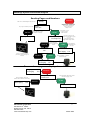
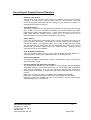
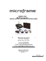
SERIES 3500
MultiPage System
INSTALLATION and SPECIFICATION GUIDE
Microframe Corporation
604 South 12th Street
Broken Arrow, OK 74012
Local: 918-258-4839
Toll Free: 800-635-3811
Website: www.microframecorp.com
E-mail: [email protected]
Manual No. B3011-7013
Revision Date: 02/2013
Control: 1.1
B3011-7013
*B3011-7013*
Limited Warranty Agreement
Your Microframe System is warranted against failure due to defects in workmanship or material for a period of
one (1) year from the date of purchase. Microframe Corporation will repair or replace any defective unit. Obvious
abuse or mishandling of the unit is NOT covered by this warranty.
Merchandise Return
If your Unit does not work satisfactorily, please give us a call. We may be able to clear up the problem by phone.
If it becomes necessary to return your Unit to the factory, please observe the following:
1. Call Microframe for an RMA number. This will authorize you to return the unit.
2. Place Unit in a sturdy box with sufficient packing material.
3. If requested, include the AC power adapter. It is not necessary to return the cable and connectors unless they
are the problem.
4. Return the system insured and prepaid. Microframe is not responsible for shipping damages and losses on
returned Units.
Warranty Service
For warranty service, please contact Microframe toll-free at 800-635-3811. One of our technicians will be glad to
assist you.
Assistance
For any product assistance or maintenance help, contact Microframe by either calling 800-635-3811 or e-mailing
us at: [email protected].
Safety
Do not install substitute parts or perform any modification to the product without first contacting Microframe.
Disclaimer
We constantly strive to improve our products. Specifications are subject to change without notice.
Warning
All power adapters, line cords, and electrical equipment should be kept out of the reach of children and away from
water. (If you are installing cable in an air plenum area, such as a drop ceiling used for air return, you must use
plenum-rated cable. The cable supplied from Microframe is rated CL2 and is approved for indoor installation
everywhere except plenum areas.)
Life Support Policy
Microframe's products are not authorized for use as components in life support devices or systems without the
express written approval of the President of Microframe Corporation. As used herein:
1. Life support devices or systems are defined as systems which support or sustain life, and whose failure to
perform when properly used in accordance with instructions for use provided in the labeling, can be reasonably
expected to result in a significant injury to the user or any one depending on the system.
2. A critical component is any component of a life support device or system whose failure to perform can be
reasonably expected to cause the failure of the life support device or system, or to affect its safety or
effectiveness.
FCC Notice (for wireless products only)
Note: This equipment has been tested and found to comply with the limits for a Class B digital device, pursuant to
part 15 of the FCC Rules. These limits are designed to provide reasonable protection against harmful interference
in a residential installation. This equipment generates, uses, and can radiate radio frequency energy and, if not
installed and used in accordance with the instructions, may cause harmful interference to radio communications.
However, there is no guarantee that interference will not occur in a particular installation. If this equipment does
cause harmful interference to radio or television reception, which can be determined by turning the equipment off
and on, the user is encouraged to try to correct the interference by one or more of the following measures:
— Reorient or relocate the receiving antenna.
— Increase the separation between the equipment and receiver.
— Connect the equipment into an outlet on a circuit different from that to which the receiver is connected.
— Consult the dealer or an experienced radio/TV technician for help.
Microframe Corporation
th
604 South 12 Street
Broken Arrow, OK 74012
800-635-3811
www.microframecorp.com
2
Series 3500
Series 3500
MultiPage System
Installation and Specification Guide
Table of Contents
MultiPage System Overview and Features
MultiPage System Instructional Diagram
MultiPage Transmitter Features and Operation
Visual-Pager® Display Features and Operation
Visual-Pager® Display Detailed Operation
Pocket Pager 2 Operation
Nexus Pager Operation
Slimline Pager Operation
Affinity Pager Operation
Microframe Corporation
th
604 South 12 Street
Broken Arrow, OK 74012
800-635-3811
www.microframecorp.com
4
5
6
8
9
11
12
13
14
3
Series 3500
MultiPage System Overview
The MultiPage System is a “plug and play” paging solution that consists of a transmitter and a display
or pager. The system may have more than one transmitter, and more than one display or pager, or
any combination of these items. With this system you may page vibrating pagers and/or send
assigned numbers to a Wireless Microframe Visual-Pager®.
System Components, Features, and Quick Operation
•
MultiPage Transmitter
The MultiPage Transmitter is unique in that it can transmit to both Wireless Microframe VisualPager® displays and vibrating pagers. The top line of the transmitter LCD screen shows the
numbers being paged, while the bottom line shows the pagers waiting to be re-paged.
To operate the system, simply plug the power adapter into the back of the MultiPage
Transmitter and into a power receptacle, and it is ready to use.
•
Wireless UHF Visual-Pager® Display
The Wireless UHF Visual-Pager® Display has been designed to receive signals from the
MultiPage Transmitter. The display is available in a 2-, 3-, 4-, or 6-digit model, each of which
has 5.5” tall red LED numbers.
Numbers sent to the display will be saved and shown on both the transmitter and the display
until manually deleted or auto-deleted depending upon user preference.
To enter a number on the Visual-Pager® display, type the number on the transmitter keypad
and press [ENTER]. To remove numbers from the display, press [CANCEL] followed by the
number(s), then press [ENTER].
•
Vibrating Pagers
The MultiPage Transmitter can be used to send messages to vibrating pagers, and to trigger
the internal “beep type” alphanumeric messages of our Pocket Pagers. The transmitter can repage these pagers at user-defined intervals. The transmitter will show on its screen the list of
pagers being re-paged.
To send a page to a vibrating pager, type the number of the pager you wish to page on the
transmitter keypad and press [SEND], then follow the transmitter’s on-screen prompts. To
remove numbers from the re-paging queue, press [CANCEL], and type the pager number
followed by [SEND].
Microframe Corporation
th
604 South 12 Street
Broken Arrow, OK 74012
800-635-3811
www.microframecorp.com
4
Series 3500
MultiPage System Instructional Diagram
Sending Pages and Numbers
A s you type in n um b ers you will see
NOTE: P ressing "C A N C E L" from
an y p oin t in the "s en d in g p ages
an d n um b ers" d iag ram will
take you back to th e
"R ead y" screen .
R eady
E nter:452
P ress "E N TE R " to send
a n u m ber to a D isplay.
ENTER
D isplay
CANCEL
R eady
A fter tu rn on, th e M u ltiP age D isp lay will sh ow
452
B E E P T YP E :(1-4)
4
R e-P age:Yes
P ress "E N TE R " to
M ove to th e M essag e
S creen
E N TE R
ENTER M ESSAGE:
567
Typ e in th e n um eric m essag e
you wan t to send to th e P ager or
In form an t.
P ress "S E N D " to send
a p ag e to a P ag er
or th e In form an t.
SEND
ENTER
OR
R e-P aging
SEND
F rom th is screen you can
c han ge the beep typ e b y typ in g
1 ,2 ,3 or 4 .
P ressing "S P A C E " will
togg le th e R e-pag e:Yes/N o.
P ress "S E N D " to
Im m ediately sen d
the P ag e.
SEND
R e-P aging
123
P ressin g "E N TE R " or "S E N D "
will send the p age.
123
To cancel a re-page or a displayed number
D isplay
R e-P aging
123
123
R eady
C ancel:123
P res sin g "E N TE R " d eletes th e
n um b er from th e W ireless U H F D isplay.
R e-P aging
123
CANCEL
ENTER
P ressing "S E N D " d eletes th e n um b er
from th e re-p agin g qu eu e.
SEND
D isplay
Microframe Corporation
th
604 South 12 Street
Broken Arrow, OK 74012
800-635-3811
www.microframecorp.com
123
5
Series 3500
Installation
The MultiPage Transmitter is designed to set on a flat surface or
table top, or to be installed on a mounting wedge for an angle or
wall mount. To use the transmitter, simply plug the 12-volt DC
power adapter into the back of the transmitter and then plug
the adapter into the wall. The transmitter is now ready to use.
MultiPage Transmitter
Operation
The MultiPage Transmitter has two primary operations.
• Send numbers to Visual-Pager® displays using the
[ENTER] key
• Page Microframe vibrating pagers using the [SEND]
key
Sending Numbers to Visual-Pager® Displays:
• To send a number to a display, simply type the
number that you want to display, i.e. “1234” and then
press [ENTER].
• To delete a number from the display, press [CANCEL]
then type the number, i.e. “1234” then press [ENTER].
Paging Vibrating Pagers:
• To send a page to a vibrating pager (i.e. pager #4), type the pager number “4” then press [SEND].
• You will then be prompted for the Beep Type. Different beep types can display up to three different
factory programmed text messages on the pager such as, "COME NOW", "NEED HELP", or
"CHILD FINE". Type in the desired beep type, or press [ENTER] to accept the default. Pressing
[SEND] from the beep type screen will page the pager with a blank message. From the message
screen you can type in the numeric message, i.e. “911” and then press [ENTER] or [SEND] to send
the page to the Pager. If re-page is "ON," you will see the message re-paging on the bottom line of
the transmitter LCD screen, followed by the number of the pager that you just paged. To stop the
re-page of a pager, press [CANCEL] then type the number of the pager, i.e. “4” and then press
[SEND].
Programmable Configurations
The MultiPage Transmitter has eight programmable options. To access these options, simply press
[SETUP] on the keypad, then press the “*“ or “#” keys to move through the list of options. When you come
to an option you would like to change, press [ENTER]. Depending on the option, you can either press the “*“
and “#” keys to change the value of the option, or you can use the numbers to type in the desired value. To
return to the main options menu press [ENTER]. When finished making changes, simply press the [SEND]
key to save the changes or the [CANCEL] key to discard your changes. Each of the eight options are
described in detail below.
OPTION 1 – Transmitter Roll-Over Time
The “Roll-Over” Time is the amount of time that each number in the transmitter memory shows on the LCD
screen before rotating to the next number. For example, with the transmitter Roll-Over Time set to three
seconds, and the transmitter with “123” and “456” in its memory, the transmitter will show “123” for three
seconds and then show “456” for three seconds and then back to “123.” To change the transmitter RollOver Time, simply use the “*“ and “#” keys to select a time from 1 to 16 seconds. When the desired time is
reached press [ENTER].
NOTE: The Transmitter Roll-Over Time is completely independent of the Display Roll-Over Time.
OPTION 2 – Auto Delete Time
The Auto Delete Time is the time that a number remains on the display before it is automatically deleted.
This time can be set using the “*“ and “#” keys to select the desired value from 1 to 25 minutes. Once the
desired value is reached, press [ENTER] to return to the main system’s options menu.
NOTE: The Visual-Pager® Display has an independent Auto Delete Time which is set following the
instructions in the Visual-Pager® Display Section.
The factory default for the display Auto Delete time is 45 minutes. The reason for having an auto delete time
in the display, as well as the transmitter, is best understood by the following example: At the end of the day,
a user may unplug the transmitter to turn it off. If there are numbers being shown on the display, they will
remain on the display until the display's auto delete removes them.
Microframe Corporation
th
604 South 12 Street
Broken Arrow, OK 74012
800-635-3811
www.microframecorp.com
6
Series 3500
MultiPage Transmitter Detailed Operation
Programmable Configurations, Options continued…
OPTION 3 – Re-Page Time for Vibrating Pagers
This is the time between re-pages for vibrating pagers. For example, if the re-page time is set to one
minute, then the pager will be re-paged every minute. Using the “*” and “#” keys, you may choose between
0 and 25 minutes for the re-page time. A re-page time of 0 disables the re-paging feature. When you have
selected your desired re-page time, press [ENTER] to return to the main options menu.
OPTION 4 – Set Display ID Address
This option is used to tell the transmitter the address of the display. The factory default is 1500. If you
change this address, you will also have to set up the display to respond to your new address (see Display
Options.)
OPTION 5 – Base ID
The Base ID is the digital identification in which all components of a system run. The factory default for this
number is 0500000. This number may be changed to avoid “cross talk” with other nearby systems. It is
recommended that users do not change this setting. If you change this ID number, then the display and
pager settings will have to be changed accordingly.
NOTE: Pager Base ID can only be changed at the factory.
OPTION 6 – Baud Rate
This is the rate at which the digital communications takes place in your system. It is recommended that
users do not change this setting. If you change this number, the display and pager settings will have to be
changed accordingly.
NOTE: Pager Baud Rate can only be changed at the factory.
OPTION 7 – Out of Range
This feature is available only with coaster systems. When the out-of-range option is activated, the
transmitter will periodically send a page telling everyone that they still are in range. If a coaster also has its
out-of-range feature activated, it will sound an alert within 1 minute of leaving the transmitter’s coverage
area.
OPTION 8 – Behavior
The behavior option exists to accommodate those users who are more familiar with the DataPage Lite
standard interface and do not need the display or re-paging capabilities of the MultiPage. The behavior
setting can be toggled between “MultiPage” and “DataPage Lite." In DataPage Lite mode, the re-page
feature is disabled and the transmitter will simply wait for a pager number and then page a pager. The
screen and button behavior will revert to the DataPage Lite operation.
MultiPage Transmitter Specifications
Paging Protocol
Frequency
Power
Coverage Area (indoors)
TX Baud Rate
Transmitter Dimensions
FCC Approval No.
Mounting
Max Numbers Shown on Display
Max Pagers in Re-Page Queue
Microframe Corporation
th
604 South 12 Street
Broken Arrow, OK 74012
800-635-3811
www.microframecorp.com
POCSAG
457.575 MHz
2 Watts
1/4 to 1/2 Mile
512 or 1200
9" x 7.25" x 2"
QBTLTK-1100H
Desk or Wall-Mount
20
30
7
Series 3500
Features
The Visual-Pager® displays are designed to work best with the
Microframe MultiPage System. The displays have two modes:
1) As a "Visual-Pager®," the display will store and rotate up to
20 numbers at a time. Numbers can be entered and deleted from
the display using the MultiPage Transmitter.
2) The display can also be used as a "Pager Confirmation
System." In this mode, the display shows the number of every
vibrating pager that has been paged.
Visual-Pager® Display
Operation
Mode 1) Using the MultiPage Transmitter, simply type in a
number and press [ENTER] to send that number to the display.
To delete a number from the display, simply press [CANCEL]
then type the number followed by [ENTER].
Mode 2) The number of any pager that is paged shows on the
display. No operator intervention is required.
24 Volt AC
9.1"
(23.1 cm)
Model 3500
Wireless
Remote Displ
ay
PROGRAM
P.O. Box 1700 , Broken Arrow, OK 74013
DATA RECEIVE LED
9.8" 2-DIGIT
(24.9 cm)
13.2" 3-DIGIT
(33.5 cm)
16.8" 4-DIGIT
(42.7 cm)
1.5"
(3.8 cm)
115 TO 24VAC
WALL MOUNTED
(WIRE-IN)
TRANSFORMER
3500\px\9700.ai
115 VAC
Visual-Pager® Display Specifications
Frequency
TX Baud Rate
Mounting
Character Height
Viewing Distance
Power Supply
Weight
Microframe Corporation
th
604 South 12 Street
Broken Arrow, OK 74012
800-635-3811
www.microframecorp.com
457.575 MHz
512 or 1200
Desk or Wall-Mount
5.5”
125 feet indoors
16 to 24 VAC
2-Digit, 2.5 lbs (1.1 kg)
3-Digit, 3 lbs (1.4 kg)
4-Digit, 3.5 lbs (1.6 kg)
6-Digit, 5.25 lbs (2.4 kg)
8
Series 3500
Visual-Pager® Display Detailed Operation
Installation
1. Wire in the power adapter. To do this, simply place one wire from the adapter under one of the
screwdown terminals and the other wire under the other screwdown terminal (refer to the wiring
diagram decal on the back of the display.) Then, plug in the power adapter and check the display
for proper operation.
2. Microframe displays can be hung on the wall similar to a picture frame. There is a keyhole in the
back of the display for this purpose.
Operation
If you purchased this Display for use with a MultiPage Transmitter, you should be able to simply plug in
the display and then enter and delete numbers as specified in the “MultiPage Operation” section. If
you are using this display with another transmitter, please read "Using the Display with Alternate
Transmitters” that is located on the following page.
Configuration
The display configurations fall into two basic categories. The first is "Display Communication Settings,"
and the second is "Display Behavior Settings." However, under normal circumstances, you will not
need to change the display configuration.
•
Display Communications Settings
The display comes from the factory ready to communicate with a MultiPage Transmitter (Base
ID 0500000, Baud Rate 1200). The display will intelligently communicate with other settings
by doing the following:
Press the button on the back of the display one time. The display will show vertical bars.
Next, page Pager number 1 with a beep type of 2 and message 7337. The display should
change to horizontal bars to signify that it has learned the transmitter identity (Base ID and
Baud Rate). If the display does not receive a valid transmission within 90 seconds, it will show
"EE".
•
Display Behavior Settings
The display's behavior can be changed by sending special codes to Pager 9999. All codes are
indicated by the form XX_XX or XX_XXXX where "_" is a space. Use the [SETUP] key to
insert a space in a message. There are five settings that can be changed using the 9999
command as seen below.
•
Mode Settings - The display has two possible Modes:
Mode 1 displays the messages sent to a specific vibrating pager.
Mode 1) To program the display to show all messages sent to Pager 300. Send a
page to Pager 9999 with the message “00_0300.”
NOTE: You must use the [SETUP] key to insert the space in the message between 00
and the Pager number. The Display will now show all messages sent to Pager 300.
Mode 2 displays all pager numbers paged by the transmitter.
Mode 2) To program the display to show all pages sent by the transmitter, send a
page to Pager 9999 with the message “00_0000.”
Microframe Corporation
th
604 South 12 Street
Broken Arrow, OK 74012
800-635-3811
www.microframecorp.com
9
Series 3500
Visual-Pager® Display Detailed Operation
Configuration, Mode Settings continued…
o
Roll-Over Time Setting
The Roll-Over Time is the time each number in the display memory is shown before
changing to the next number. This time can be set from 1 to 9 seconds. To set this
time, send a page to Pager 9999 with the message “01_0X” where X is a number 1-9
representing the number of seconds.
o
Auto Delete Setting
The display can be set to automatically delete a number from its memory after a preset
time. NOTE: If you have a MultiPage Transmitter, use the transmitter's auto delete
rather than the display's auto delete time. To set the auto delete time, send a page to
Pager 9999 with the message “02_XX” where XX is a number from 1 to 42
representing the number of minutes to wait before auto deleting.
o
Chime Setting
If you have purchased an optional triac circuit, it can be activated every time a new
number is sent to the display. The duration of the triac output can be controlled by
changing this option. To change this option, send a page to 9999 with the message
“03_XX” where XX is a number from 00 to 99 representing the number of 0.1 second
intervals that you want the output to be on (i.e. 99=9.9 seconds). Sending a 00 will
cause the triac circuit to be disabled.
o
Clear All Numbers Command
There are occasions where you may want to clear all numbers from all displays. To
clear all numbers, send a page to Pager 9999 with the message “99_98.”
o
Reset Factory Defaults
To change the display settings back to factory defaults send a page to Pager 9999
with the message “99_99.”
o
Using the Display with Alternate Transmitters
The Visual-Pager® Display has been designed to work optimally with the MultiPage
Transmitter. However, in rare cases you may want to use the display with a transmitter
other than the MultiPage. If so, you can control the display's basic functions by
sending pages to the display’s address with beep types and messages to control the
function.
Beep Type “4” enters the number contained in the message into the display.
Beep Type “3” removes the number contained in the message from the display.
Example: to add "123" to display ID 1500, do the following. Send a page to Pager
1500 with beep type 4, message 123.
Microframe Corporation
th
604 South 12 Street
Broken Arrow, OK 74012
800-635-3811
www.microframecorp.com
10
Series 3500
Features
The Pocket Pager 2 is designed to work with the MultiPage
family of on-premise transmitters. The battery-powered pager
can show any numeric message sent by the transmitter.
Optionally, the pager can show up to three factory preprogrammed text messages corresponding to the beep type
specified.
Pocket Pager 2
Turning on the Pager
Hold down the LARGE BLACK BUTTON until the pager comes
on.
Sending A Page
Please see the diagram in the MultiPage section of this manual
for detailed instructions on sending pages.
Activating a Pre-Defined Message
To activate a pre-defined message on a vibrating pager, type in the pager number followed by the [SEND] key.
You will be prompted for a “BEEP TYPE (1-4).” Select 1-3 here and press the [SEND] key. This will display on
the pager one of the three pre-programmed text messages stored in the pager. If no number is chosen, the pager
will default to Beep Type 4 (“PAGING”).
Sending a Numeric Message
To send a numeric message to a pager, simply type in the pager number followed by the [SEND] key. The
transmitter screen will display “BEEP TYPE.” Simply press [ENTER] to bypass this. The transmitter screen will
then display “ENTER MESSAGE.” Using the number keys, type in a numeric message up to 16 digits followed by
the [SEND] key. Note: If the message portion of a page is not blank the “BEEP TYPE” pre-defined message
selected will be ignored.
Receiving a Page
The Pocket Pager 2 will start to vibrate when it is paged. No action is necessary on the receiving end. The pager
will stop vibrating after approximately eight seconds. If the user would like to stop the vibration before the eight
seconds, simply press the LARGE BLACK BUTTON. If a numeric message is sent to the pager, the message will
be visible on the pager's LCD screen until the pager stops vibrating. To view the message after the pager has
stopped vibrating, press the LARGE BLACK BUTTON once.
Sending a Group Call Page
All pagers respond to call number “900” (unless another group call number has been chosen by the customer and
programmed at the factory). To page all pagers at once, simply enter “900” and [SEND]. Then press [SEND]
again at the beep type prompt.
Manual Pager Turn-Off
Press the [DOWN ARROW] button until you see the words “PGR OFF” on the LCD screen. Press the LARGE
BLACK BUTTON once to confirm. NOTE: If you have chosen to order the pagers with the on/off button disabled,
then pagers can be turned off from the transmitter. If you want the off/on button activated on the pager; this must
be requested at time of purchase.
Pager Turn-Off from Base
Enter the pager number followed by the [SEND] key. Press [ENTER] to bypass “BEEP TYPE” screen. When
screen reads “ENTER MESSAGE,” enter the message code “*0“ followed by [SEND]. Since all pagers respond to
call number “900,” paging “900” with the message code “*0” will turn all pagers off.
Lighting Function
Pressing the [UP ARROW] button will turn on the backlight on the LCD screen. The light will shut off automatically
after approximately 30 seconds, or the user may turn the light off manually by pressing the [UP ARROW] button
once.
CAUTION
a) The pager is made up of LCD and precision elements. Avoid water and high temperature.
b) Remove the battery if the pager will not be in use for a long period of time.
c) If the pager is not working properly, do not dismantle or repair it yourself. Call Microframe for technical service.
Microframe Corporation
th
604 South 12 Street
Broken Arrow, OK 74012
800-635-3811
www.microframecorp.com
11
Series 3500
Features
The Nexus Pager is designed to work with the MultiPage family of
on-premise transmitters.
The rechargeable pager can show
unlimited numeric messages sent by the transmitter. Optionally, the
pager can show up to three factory pre-programmed text messages
corresponding to the beep type specified.
Nexus Pager
Turning on the Pager
Hold down the RED BUTTON on the side until the pager comes on.
Sending A Page
Please see the diagram in the MultiPage section of this manual for
detailed instructions on sending pages.
Activating a Pre-Defined Message
To activate a pre-defined message on a vibrating pager, type in the
pager number followed by the [SEND] key. You will be prompted for
a “BEEP TYPE (1-4).” Select 1-3 here and press the [SEND] key.
This will display on the pager one of the three pre-programmed text
messages stored in the pager. If no number is chosen, the pager will
default to Beep Type 4 (“PAGING”).
Sending a Numeric Message
To send a numeric message to a pager, simply type in the pager number followed by the [SEND] key. The transmitter
screen will display “BEEP TYPE.” Simply press [ENTER] to bypass this. The transmitter screen will then display
“ENTER MESSAGE.” Using the number keys, type in a numeric message up to 16 digits followed by the [SEND] key.
Note: If the message portion of a page is not blank the “BEEP TYPE” pre-defined message selected will be ignored.
Receiving a Page
The Nexus pager will start to vibrate when it is paged. No action is necessary on the receiving end. The pager will stop
vibrating after approximately eight seconds. If the user would like to stop the vibration before the eight seconds, simply
press the RED BUTTON on the side of the pager. If a numeric message is sent to the pager, the message will be visible
on the pager's LCD screen until the pager stops vibrating. To view the message and turn off the flashing lights, press the
RED BUTTON three times.
Sending a Group Call Page
All pagers respond to call number “900” (unless another group call number has been chosen by the customer and
programmed at the factory). To page all pagers at once, simply enter “900” and [SEND]. Then press [SEND] again at
the beep type prompt.
Manual Pager Turn-Off
Press the RED BUTTON on the side of the pager for 5 seconds or place pager on the charging base.
Lighting Function
Press the RED BUTTON on the side of the pager.
Changing the Alert Mode
Pagers may be programmed to respond to a page by flashing lights; flashing and beeping; flashing and vibrating; or
flashing, vibrating and beeping. By default, the pagers are programmed to flash and vibrate for 8 seconds.
To change the alert mode, follow these instructions: Remove all the pagers from the charging unit or unplug the power
supply that is connected to the charging base. Wait for the demo page to stop (about 7 seconds). Press "1248" followed
by [SEND] and [ENTER]. For the message, enter the code that corresponds to the alert that you want (see below.) For
example, if you want the pagers to flash only, press "1248-SEND-ENTER-9797-SEND." After sending the code, the
lights on all the pagers will flash to indicate the programming was received. Return all the pagers to the charging base or
plug the power supply back in. The pagers are ready to receive the page with the new alert.
Flash & Beep
Flash & Vibrate
Flash Only
Flash, Vibrate & Beep
"9595"
"9696"
"9797"
“9898"
CAUTION
a) The pager is made up of LCD and precision elements. Avoid water and high temperature.
b) Remove the battery if the pager will not be in use for a long period of time.
c) If the pager is not working properly, do not dismantle or repair it yourself. Call Microframe for technical service.
Microframe Corporation
th
604 South 12 Street
Broken Arrow, OK 74012
800-635-3811
www.microframecorp.com
12
Series 3500
Features
The Slimline Pager is designed to work with the MultiPage family
of on-premise transmitters. The rechargeable has vibrate-only
and LED alert capability.
Slimline Pager
Sending a Page
Please see the diagram in the MultiPage section of this manual
for detailed instructions on sending pages.
Sending a Group Call Page
All pagers respond to call number “900” (unless another group
call number has been chosen by the customer and programmed
at the factory). To page all pagers at once, simply enter “900”
and [SEND]. Then press [SEND] again at the beep type prompt.
Changing the Alert Mode
Pagers may be programmed to respond to a page by vibrating,
flashing lights, flashing and vibrating. By default, the pagers are
programmed to flash and vibrate for 3 minutes.
To change the alert mode, follow these instructions: Remove all
the pagers from the charging unit or unplug the power supply that is connected to the charging base. Wait for the
demo page to stop (about 7 seconds). Press "1248" followed by [SEND] and [ENTER]. For the message, enter
the code that corresponds to the alert that you want (see below.) For example, if you want the pagers to flash
only, press "1248-SEND-ENTER-9797-SEND." After sending the code, the lights on all the pagers will flash to
indicate the programming was received. Return all the pagers to the charging base or plug the power supply back
in. The pagers are ready to receive the page with the new alert.
Vibrate Only
Flash & Vibrate
Flash Only
"9292"
"9696"
"9797"
CAUTION
a) The pager is made up of precision elements. Avoid water and high temperature.
b) Remove the battery if the pager will not be in use for a long period of time.
c) If the pager is not working properly, do not dismantle or repair it yourself. Call Microframe for technical service.
Microframe Corporation
th
604 South 12 Street
Broken Arrow, OK 74012
800-635-3811
www.microframecorp.com
13
Series 3500
Features
The Affinity Pager is designed to work with the MultiPage family of
on-premise transmitters. The rechargeable vibrating pager has
illuminating lights, vibrate and tone alert options for personalization.
Affinity Pager
Sending a Page
Please see the diagram in the MultiPage section of this manual for
detailed instructions on sending pages.
Sending a Group Call Page
All pagers respond to call number “900” (unless another group call
number has been chosen by the customer and programmed at the
factory). To page all pagers at once, simply enter “900” and [SEND].
Then press [SEND] again at the beep type prompt.
Changing the Alert Mode
Pagers may be programmed to respond to a page by vibrating;
flashing lights; flashing and beeping; flashing and vibrating; or flashing, vibrating and beeping. By default, the
pagers are programmed to flash and vibrate for 8 seconds.
To change the alert mode, follow these instructions: Remove all the pagers from the charging unit or unplug the
power supply that is connected to the charging base. Wait for the demo page to stop (about 7 seconds). Press
"1248" followed by [SEND] and [ENTER]. For the message, enter the code that corresponds to the alert that you
want (see below.) For example, if you want the pagers to flash only, press "1248-SEND-ENTER-9797-SEND."
After sending the code, the lights on all the pagers will flash to indicate the programming was received. Return all
the pagers to the charging base or plug the power supply back in. The pagers are ready to receive the page with
the new alert.
Vibrate Only
Flash & Beep
Flash & Vibrate
Flash Only
Flash, Vibrate & Beep
"9292"
"9595"
"9696"
"9797"
"9898"
CAUTION
a) The pager is made up of precision elements. Avoid water and high temperature.
b) Remove the battery if the pager will not be in use for a long period of time.
c) If the pager is not working properly, do not dismantle or repair it yourself. Call Microframe for technical service.
Microframe Corporation
th
604 South 12 Street
Broken Arrow, OK 74012
800-635-3811
www.microframecorp.com
14
Series 3500