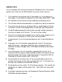
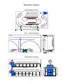
1
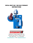
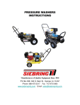
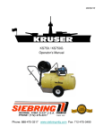
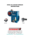
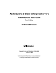
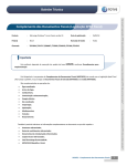
ROYAL HEAT 240 / 360 GAS FURNACE
INSTRUCTIONS
ATTENTION!
See special Methane
instructions on page 2425 & H17 pilot insert in
the back of this manual
Manufacturers of Quality Equipment Since 1910
PO Box 658 303 S. Main St. George, IA. 51237
Phone 888-475-3317 Fax 712-475-3490
www.siebringmfg.com Email [email protected]
TABLE OF CONTENTS:
1.
Cover
2.
Table of Contents
3.
Condition of Sale - Warranty
4.
Warnings & Cautions
5.
General Information
6.
General Information & Instructions
7.
New Installations
8.
Placement
9.
Placement Options
10. Venting
11. Venting (continued)
12. Gas Supply Information
13. CO Level Standards
14. Gas Pipe Capacities
15. Pilot Adjustment
16. Square D electrical box
17. Electrical Diagram
18. Troubleshooting
19. Troubleshooting (continued)
20. Troubleshooting (continued)
21. Troubleshooting (continued)
22. Parts List
23. Parts Diagram – Furnace
24. Parts Diagram – Burner Tray
25. Special Requirements for Methane Furnaces
26. Special Instructions for Methane Furnaces
27. Specifications (dimensions, weight)
28. Specifications (continued) safety zone
Included: Robertshaw Gas Valve Installation Pamphlet, Honeywell
L4064 Fan & Limit Pamphlet, Honeywell Q327 Pilot Burners
Pamphlet, H17 Pilot Valve.
2
CONDITION OF SALE
SIEBRING MANUFACTURING, INC.
GEORGE, IA 51237
Pursuant to Magnuson-Moss Warranty Federal Trade Commission Improvement
Act P.L. 93-637, 88 STAT.2183-2193; U.P.C. 2301-2312 (Jan. 4, 1975), the
following limited warranty will now replace all prior warranties issued by Siebring
Manufacturing, Inc.
We warrant the equipment manufactured by us to be free from defects in material
and workmanship under normal use and service, our obligation under this
warranty being limited to replacing at our factory any product, or parts thereof,
which shall within one year after delivery thereof to the original purchaser be
returned to us with transportation (UPS Ground) charges prepaid, and which our
examination shall disclose to our satisfaction to have been thus defective. We
neither assume nor authorize any other person to assume for us any other liability
in connection with such equipment. “Overnight”, “Next Day” or any shipping
method other than UPS Ground will be the responsibility of the customer. This
warranty shall not apply to any equipment which shall have been repaired or
altered outside of our factory in any way so as to affect its stability and reliability,
nor which has been subject to misuse, negligence or accident, nor to any
equipment, which shall have been operated beyond factory rated capacity. We
shall not be liable for consequential damages caused by defective materials,
equipment or parts warranted by their respective manufacturers.
Any implied warranty (including the warranty of merchantability), to the extent
permitted by law, is excluded.
We will not grant any allowance for any repairs or alterations without written
approval of an executive officer, and we reserve the right to make changes in
design, or to make additions to, or improvements in, our products without
imposing any obligations upon the company to install them on products previously
manufactured.
Siebring Manufacturing is not responsible for installation costs.
3
FOR YOUR SAFETY
IF YOU SMELL GAS:
1. OPEN WINDOWS.
2. DON’T TOUCH ELECTRICAL SWITCHES.
3. EXTINGUISH ANY OPEN FLAMES.
4. DO NOT TRY TO LIGHT THE FURNACE
5. IMMEDIATELY CALL YOUR GAS SUPPLIER.
WARNING: Improper installation, adjustment, alteration,
service or maintenance can cause property damage,
injury or death. Read the installation, operating and
maintenance instructions thoroughly before installing or
servicing this equipment.
4
GENERAL INFO:
This unit complies with the American National Standard for Gas Unit Heaters
(special units, which are not AGA certified, may also use this manual).
1.
The installation must conform with all local codes, or, in the absence of
local codes, it must follow the National Fuel Gas Code, ANSI Z223.1-1988.
2.
All installation and servicing must be handled by qualified personnel.
3.
This furnace should not be operated in an explosive or dusty environment.
4.
This unit can be set up to run on Natural Gas or Liquid Propane (LP) gas.
The orifices must be sized appropriately for each gas type and pressure.
5.
The draft hood provided with each furnace must be installed vertically in
the same air space as the furnace. This unit must be vented.
6.
If this unit is used to heat an adjacent area, (not the same airspace as the
furnace is in) an adequate air return area must be provided.
7.
In greenhouses, this unit may be positioned on four (4) concrete block or
bricks.
8.
In garages, this unit should be suspended with at least 7’ of clearance
under the furnace. In garages, install this unit in accordance with the
Standard for Repair Garages ANSI / NFFA 88B and follow all local codes
that apply.
9.
In aircraft hangars, this unit should be suspended with at least 10’ of
clearance from the wings or engine cowling, based on the highest aircraft
normally stored in the hangar. Install this furnace in accordance with the
Standard for Aircraft Hangars ANSI / NFPA 409.
10. Do not locate this unit closer than 12” to any combustible material, this
includes the chimney, all four sides and top of the unit. The furnace may
be set on any suitable non-combustible material.
11. Do not locate any items within 12” of the burner opening. This includes the
combustion air supply and the blower inlets. Floor drafts can cause pilot
outages.
12. If installed in parking structures, the Standard for Parking Structures ANSI /
NFPA 88A should be followed.
5
24”
The chimney height will be determined by the
surrounding roof & trees. The chimney should
extend at least 24” above the high point of the
roof with no obstructions from nearby roofs,
trees or other structures.
THIMBLE
Draft Cap
The vent pipe should extend only to
(and not beyond) the inside wall of the
chimney. Cement vent pipe tightly into
chimney opening.
Trim or remove any nearby trees that
would interfere with chimney draft
DIRECTION OF FLOW
MANUAL SHUTOFF
VALVE
DRAFT
DIVERTER
TEE
UNION
12”
EXTENSION
(RH360)
3” MIN
CONTROL MANIFOLD
PIPE CAP
Gas fired units will require less draft than coal
fired, however, a chimney flue with adequate
draft and capacity is required. An A.G.A. draft
diverter must be installed on all gas-fired
heating units.
FLOOR LEVEL
⅛” N.P.T. PLUGGED TAPPING
PRESSURE GAUGE PORT
Location of union and drip leg for connecting
conversion burner to house piping
RH240 Requires
8” Ø Stack
ROYAL
Heaters
RH360 Requires
9” Ø Stack
RH360 Requires
a 12” Extension
between furnace
and draft diverter
20 ft.
General Information & Instructions
10 ft.
-Unit crated weights: 240 = 640 lbs. / 360 = 780 lbs.
-Always use double wall pipe on gas units.
-Never have less than .02 - .04 inches of draft in the chimney.
I
I
-Always use black metal piping for gas (Nat./L.P.) installations.
-Rule of thumb for chimneys = 2’ vertical for every 1’ horizontal.
240
-Always check with the gas company on appropriate pipe sizing.
-Always check with the gas company to ensure adequate fuel supply.
-Never reduce the size of chimney from the furnace to the draft cap.
-Never run exhaust fans in any building while furnaces are in operation.
-Always vent gas fumes. Gas fumes not vented can cause death to plants, animals and humans.
-The draft diverter must always be installed VERTICALLY unless otherwise stated by Siebring Mfg.
Warranty will be void if venting does not meet local codes for gas venting.
6
360
NEW INSTALLATIONS
Electrical Information
Important!
Before beginning any electrical work, be
certain the electrical supply is disconnected.
For the furnace to operate properly, it must
be wired exactly as outlined in this manual.
Connect to 120 VAC 60 HZ 25A Service
An electrical diagram has been provided in this manual and on the face of the furnace.
1.
If any wires as originally supplied are replaced, they should be replaced with type “T”
wires, with a 63°F (35°C) rise wire in similar colors.
2.
Follow all local codes when wiring this furnace.
3.
This furnace must be electrically grounded in accordance with the National Electrical
Code, ANSI / NFPA 70.
WIRE SIZE
RATING @ 140°
14-3
12-3
10-3
8-3
15 AMP
20 AMP
30 AMP
40 AMP
LINE LOSS WITH 15AMP
LOAD IN 100’ COPPER WIRE
8.0 VOLTS LOSS
5.5 VOLTS LOSS
3.0 VOLTS LOSS
1.9 VOLTS LOSS
Wire Size for 115 & 230 Volt Single Phase Circuits
Distance – Motor to Fuse or Motor to Meter Box
MOTOR
HP
100 FT.
200 FT.
300 FT.
500 FT.
115V
230V
115V
230V
115V
230V
115V
230V
1/4
# 14
# 14
# 10
# 12
#8
# 10
#6
#8
1/3
# 12
# 14
# 10
# 12
#6
# 10
#4
#8
1/2
# 10
# 12
#8
# 10
#6
#8
#4
#6
3/4
# 10
# 12
#6
# 10
#4
#8
#2
#6
1
#8
# 10
#6
#8
#4
#6
#4
1½
#4
# 10
#0
#8
#6
#4
2
#8
#6
#4
#2
3
#8
#6
#4
#2
5
#6
#4
#2
#0
7
PLACEMENT:
This unit is designed to be used in various configurations. In greenhouses it
may be positioned directly on the ground or suspended from the greenhouse
structure. In aircraft hangars or garages, the unit will need to be suspended.
1.
This unit may be suspended if necessary. Suitable framework, capable of handling
the weight of the furnace, can be fabricated from angle, channel or tubing material.
An eye bolt can be inserted in each corner or end of the angles, channels or beams to
provide 4 corner support (4 req.). These bolts can then be installed thru a suitable
ceiling joist etc.
2.
Obviously, the structure must be strong enough to carry the additional weight of the
furnace, snow load and any possible future modifications or additions.
240 RH – 650#, 360 RH – 780#.
2.
In greenhouses, this unit is normally installed on four (4) bricks setting directly on the
ground. A variety of openings can be supplied on these furnaces.
3.
The furnaces require:
A. 12” distance to any combustible material. (See General Info for exceptions)
B. 12” of space for combustion air and blower supply air.
C. Approximately 1 sq. ft. of inlet area per 150,000 BTU/hr input. In many cases,
normal building cracks make up more than this area.
D. Approximately 5 sq. ft. of return air area. The heated air must have a free path
out of and back to the furnace. DO NOT restrict the discharge vents.
E. A barometric device (supplied by the manufacturer) in the same room as the
furnace. On the RH360 model, a 12” extension must be installed between the
barometric device and the furnace to prevent back draft and to prevent flue gases
from entering the blower inlet.
F. Plenty of access space for servicing the blower motor, burner, etc. Access must
also be provided to reach the gas valve and shut offs in case of an emergency.
G. That all local codes are followed when installing the regulation flue pipes.
8
Placement Options
End Broadcast & Fan
Furnace
Horizontal Airflow
Fan
Fan
6’
40’
Inter – House Heating
Note:
- 24” sq. air returns (fan assist) on each end of the greenhouse
- One heat unit for two houses is not recommended
Heated Air
Heated Air
Under Bench Heating
Air forced under bench through poly-tubing duct.
Heated Air
Air forced under bench. Bench covered with used poly.
Heated Air
Used Poly
9
VENTING
Vent connectors serving Category I & Category II heaters shall not be connected into any
portion of mechanical draft systems operating under positive pressure.
This furnace is equipped with a blocked vent shut off system.
DO NOT attempt to run this furnace until a qualified service man has checked the
installation.
INSTALLATION
The installation must conform with local building codes or in the absence of local codes, the
installation must conform with the National Fuel Code, ANSI Z223.1
Your furnace has been provided with a Draft Hood. This device must be used. This
furnace also requires a blocked vent shut off device or spill switch (snap disc). The
electrical schematic shows how this device is wired into the furnace controls. This device
must be reset each time the sensor detects a venting failure. If the Blocked Vent switch
has locked the system out, contact a qualified service man before attempting to restart the
furnace.
NOTE: Negative room pressures in buildings with exhaust fans will cause the blocked vent
device to lock the gas valve out. (Heating will cease)
GENERAL RULES
1.
Do not reduce the stack size anywhere in the entire vent system..
2.
The stack must not be closer than 12” to any combustible material.
3.
All horizontal runs must slope upwards not less than ¼” per foot from the heater
towards the vertical riser or extension.
4.
All horizontal runs must be supported to prevent sagging.
The venting may be supported by steel strap or wires around the tube and tied up to
any convenient overhead support. Supports must be provided at each connection.
5.
Each connection should be secured by at least three sheet metal screws. More may be
necessary depending upon installation.
6.
The stack must be installed in such a manner to prevent accumulation of condensation.
7.
If required, the stack must have a method of draining the condensation.
8.
Use any type B flue or vent connectors. Unless local codes specify a superior type of
flue or vent connectors.
9.
Venting failures can be caused by adverse weather, exhaust fans being on at the same
time as the furnace, inadequate make up air supply, lack of down-draft cap, etc.
10. Never allow less than 2’ vertical pipe for each 1’ of horizontal vent pipe.
11. Draft should never be less than .02” WC nor over .05” WC.
10
C
E
I
J
B
F
V
A
D
H
F
I
A.
Draft Diverter
B.
Horizontal Flue (must slope up ¼” per foot)
C.
Vertical Flue (must be twice as tall as horizontal distance - B)
D.
Alternate stack design for free standing support
E.
Chimney should extend 2 – 4 feet above high point of roof
F.
A “Tee” instead of an elbow is recommended on the bottom of the vertical stack to
facilitate water drainage and chimney cleaning. Install a cap on the bottom of the “Tee”.
“V” – Vertical Chimney Height (must be at least twice as long as “H”)
“H” – Horizontal Pipe (must slope upwards away from furnace, ¼” per foot of horizontal
distance)
“I” – Draft 0.02 to 0.04 inches of water column (measure below draft diverter)
“J” – Install 12” to 24” riser between draft diverter and top of furnace.
DO NOT OPERATE THIS UNIT WITHOUT VERTICAL FLUE PIPE!
PROPER DRAFT MUST BE MAINTAINED TO PREVENT DANGEROUS
GASES FROM ENTERING THE BUILDING……………………..
11
GAS SUPPLY INFORMATION
This furnace is designed to run on several gas types. Natural and LP are the most
common. Each furnace is set up for one type of gas. DO NOT attempt to burn another
type of gas without replacing proper burner and gas valve modifications.
1.
An Individual shut off valve is required for each furnace before the gas regulator.
2.
The heater and its individual shut off valve must be disconnected from the gas supply
piping system during any pressure testing of that system at test pressure in excess of
½ PSIG (3.5kPa).
3.
The heater must be isolated from the gas supply piping system by closing it’s own
individual manual shut off valve during any pressure testing of the gas supply piping
system at test pressures less than or equal to ½ PSIG (3.5kPa).
4.
A 1/8” NPT, plugged tapping, accessible for test gauge connections, must be installed
immediately upstream from the gas supply connection to the heater.
5.
The combustion chamber may be cleaned with compressed air thru the stack opening
and thru the fresh air inlet. (Remove the burner tray.) The burner manifold and
nozzles may be brushed off and cleaned with compressed air. Any blocked nozzles
may be opened by pushing a soft wire through the opening in the nozzle. DO NOT
enlarge the nozzle orifices.
6.
Type of Gas
LP
Nat.
Max Inlet Supply (to valve)
14
6
Manifold
11
3½
Minimum Valve Inlet
11
4½
All pressures are measured in “Inches of Water Column” for manifold pressure.
7.
To convert from one gas type to another
A. Main Burner Orifices – LP (red colored Manifold) #63 drill size
NAT (plain cast gray manifold) #52 drill size
B. The orifice may be unscrewed and the correct orifices screwed back in.
Pilot Orifice – LP (red colored)
NAT (plain)
C. The entire pilot assembly should be removed and the correct pilot installed. The
pilot line should be aluminum. Gas Valve Regulator Spring – LP (red colored), NAT
(plain).
The large slotted screw on the top of the regulator should be removed to exchange
regulator springs. After any of these changes are made, manifold gas pressure tests
must be made. The gas valve must be adjusted correctly for proper furnace
performance and operation. Water column manometers are preferred over dial type
manometers.
12
13
14
Furnace Adjustments
Pilot Adjustment
The pilot flame should bathe the thermocouple in flame (1 ½” – 2”). Each gas valve has a pilot
flame adjustment. Remove the screw beside the pilot gas line on the gas valve.
The adjustment screw is down in this threaded hole. Turn counter-clockwise to increase flow.
⅜ TO ½ INCH
Approx. 2”
PILOT
THERMOCOUPLE
Pilot Burner Adjustment (on gas valve):
1. Remove Pilot adjustment cap.
2.
3.
4.
Adjust pilot key to provide properly sized flame. 2” preferred.
Clock-wise to decrease, counter clock-wise to increase
Replace pilot adjustment cap.
Leak test.
To Light Pilot – Follow procedures on page 3, “Operating Instructions” of the “Robertshaw
Installation Data” insert in the rear of the manual.
Main Burner Adjustment
The gas system should have its pressure tested. See Rating Plate for required pressures.
See “Robertshaw Installation Data” in appendix for more information about these valves.
The gas valve has an adjustable pressure regulator. The largest screw on the top of the gas
valve must be removed to gain access to the adjustment screw. Turn clock-wise to increase
the flow.
Blower Belt Adjustment
The blower belt must be loose enough that ½” to 1” of belt deflection can be obtained with a
gentle push on the belt, mid-point between pulleys. Furnace power must be off while
performing this check.
Fan & Limit Adjustments
Each fan and limit has three settings. Before making any adjustments, the rotating dial must
be held in place with one finger or thumb while another finger on the other hand is used to
change the setting, being careful not to damage or strain the sensing element.
- Fan Stop 80°- 90°
User Selectable
- Fan Start 110°- 120° User Selectable
- High Limit 170°- 180°
15
SQUARE D BREAKER BOX – RH360
Common
Connect to 120 VAC
60 HZ 25A Service
L1, Line In
Ground
Lug
25
Neutral
To Blower
Motor
To Fan & Limit
Switch
To Transformer
16
Royal Heat – Gas
240 / 360
200°Snap Disc
Connect to 120 VAC
60 HZ 25A Service
CB
Fan & Limit
180°Snap Disc
To Blower
Motor
To
Blue
Bird
switch
To
Terminal
block
To “Blue Bird” switch
Transformer
120V to 24V
To Thermostat
Gas Valve
Robert Shaw 700-406
17
TROUBLESHOOTING
1.
Blower motor – heats up and trips out thermal protector on motor or the main breaker
on power source.
A. Belt tension too tight
Loosen belt (1/2” – 1” deflection)
B. Electrical supply wiring & distance exceeded
Install correct wire gauge, usually larger
C. Blower bearing will not turn freely
Replace or oil bearings
D. Bad motor (amp draw, shorted…)
Take motor to authorized repair center or replace
E. Higher amp draw due to lack of air restriction
Replace or reinstall blower inlet guards (increase outlet restriction on furnace)
2.
Blower motor – does not start
A. Reset button or auto-reset device on motor
Push in to reset (manual)
Allow motor to cool, reset will be automatic
B. Bad motor
Take motor to authorized repair center or replace
C. Fan & limit switch (defective)
Check settings (factory 90°/ 110°/ 170°) or replace
D. Loose wire or connection
Tighten / secure as required
3.
Blower shakes (vibrations)
A. Belt tension/condition
Correct tension or replace belt
B. Pulley condition
Check for split, worn or bent pulley
C. Blower bearing
Replace as required
D. Blower wheel condition / dust build-up
Replace or clean, check for missing balance weights
18
TROUBLESHOOTING
(continued)
4.
Unable to light pilot
A. First time light attempt – air in gas line
Purge air from gas line (test gas supply pressure)
B. Blocked pilot orifice
Clean or replace
C. Check gas supply
Gas line connected? Valve open?
D. Pilot out of adjustment
Open up needle valve (counter clock-wise to increase)
E. Blocked or defective gas valve
Replace gas valve
5.
Pilot won’t stay lit after releasing gad cock dial, goes out immediately
A. Inadequate pilot gas flow
Clean orifice with compressed air / increase pilot gas flow (CCW)
B. Bad thermocouple / corroded connection to gas valve
Replace, clean, check/tighten connections on gas valve
C. Bad gas valve
Replace by qualified service person
D. Downdraft through furnace
Draft hood installed? Exhaust fan on?
6.
Pilot won’t stay lit (intermittently) goes out at night…
A. Inadequate pilot gas flow
Clean pilot orifice / increase needle valve flow
B. Weak thermocouple
Replace
C. Draft through furnace
Is draft diverter installed? Exhaust fan on? Weak pilot gas flow
19
TROUBLESHOOTING
(continued)
7.
8.
9.
Main burner will not light – test gas pressure
A. Thermostat not calling for heat
Raise thermostat setting / replace thermostat
B. Check preceding pilot tips
Proceed as required
C. Bad transformer
Replace if 120V in, nothing out. 24V is correct
D. Bad gas valve
Replace by qualified technician
Main burner lights weakly – test gas pressure, tank level
A. L.P. – Inadequate gas tank temperature or evaporation area
B. Tank valve undersized and freezing up.
Increase valve size / capacity
C. Supply piping too small
Increase pipe size
D. Wrong gas type
Check gas type, replace orifices, pilot…
E. Bad gas valve
Replace by qualified technician
F. Poor gas quality
Connect to good gas supply
G. Gas pressure too low to unit
Increase line pressure
H. Too many heaters on an inadequate supply line
Re-engineer full “Heater On” gas demand
Main burner lights harshly, delayed ignition
A. Gas pressure too high
Decrease gas pressure, see “Robertshaw Installation Data”
B. Wrong gas type
Check gas type, replace orifices, pilot…
C. Bad gas valve
Replace by qualified technician
D. Pilot too small
See pilot troubleshooting section
E. Incorrect orifices
Check correct orifice size, replace as required
20
TROUBLESHOOTING
(continued)
10. Blower motor starts and stops frequently (while main burner is on)
A. Improperly set fan & limit switch
Set switch to proper temperatures (90°/ 110°/ 170°)
B. Defective fan & limit switch
Replace
C. Furnace is not at full firing rate
See main burner section
11. Discharge air too hot / too cold
A. Check firing rate
Check gas pressures, orifice size
B. Improperly set fan & limit switch
Set switch to proper temperatures (90°/ 110°/ 170°)
C. Defective fan & limit
Replace
D. Blower belt slipping / blower speed is improper
Correct belt tension / check motor or blower pulley size
Special Note: Contact gas supplier to engineer gas unit demands and distribution systems
21
RH240 / RH360 Parts (When ordering parts, specify L.P, Natural gas or methane)
1.
Draft Diverter
2.
Snap Disc - 200° (Draft Diverter)
3.
12” X 9” Ø Pipe extension (RH360 only)
4.
Breaker box
5.
25 Amp Breaker
6.
Fan & Limit Switch
7.
Snap Disc – 180° (Furnace Shell)
8.
24V Transformer
9.
Terminal Block, low voltage
10. Blower Motor * (RH240 - ¾ HP, RH360 – 1 HP) DO NOT replace
blower motor with farm duty or manual reset model.
11. Drive (motor) Pulley (RH240 – 4 ½”, RH360 – 3 ¾”)
12. Motor Mount Bracket (RH240 – Small, RH360 – Large)
13. Drive Belt (RH240 – 47”, RH360 – 49”)
14. Driven (blower) Pulley – 9”
15. Blower (RH240 – Small Lau, RH360 – Large Lau)
16. Belt Guard
17. Blower Guard (not shown)
18. Burner Tray (specify 240 or 360)
19. High Limit “Blue Bird” safety device
20. Orifice (L.P. # 63 / Nat. # 52)
21. Aluminum Tubing
22. Gas Valve
23. ¾” Street Elbow
24. ¾” X 12” Pipe Nipple
25. Tray Cover (360 only)
26. Manifold (specify 240 or 360)
27. Thermocouple
28. Pilot assembly (L.P.- Black fitting / Nat. – Silver fitting)
22
RH240 / RH360 Parts
1
10*
11
12
13
2
3
4
5
6
2
5
A
14
7
15
8
16
17 Not Shown
9
Parts may not be
drawn to scale
18
23
20
19
18
21
25
22
23
24
26
Side View
27
28
Top View
27
Pilot & Thermocouple
21
24
28
Special Instructions – Methane RH240 / RH360
Methane Requirements:
-A minimum of 3 PSI to a regulator rated at a minimum of 1,000,000 BTU
located within 10’ of the furnace.
-Gas must be regulated down to 13” of W.C. before the gas valve and 11.5” of
W.C. after the gas valve.
-The pressure and W.C. requirements must be met for each unit and checked
while all units in the facility are in operation.
-Use a minimum of 1” I.D. flex gas pipe or 1” I.D. gas rated flexible hose long
enough to allow for burner tray removal (approximately 6 feet). This will
facilitate lighting of the pilot and test burning of the nozzles.
-Nozzle size will be determined by CO2 and BTU rating requirements.
-Pilot can be L.P. or Natural gas and must be specified at the time of the order.
-Standard methane nozzle is # 49. Anything different must be specified at the
time of the order.
-Gas must be lab tested for proper nozzle sizing.
25
Special Instructions – Methane RH240 / RH360
Lighting the pilot:
1.
Turn wall thermostat to it’s lowest setting
2.
Turn gas cock dial to “OFF” position
3.
WARNING: Wait at least 5 minutes to allow any gas in the combustion
chamber or burner area to vent. If you smell gas in the appliance area or
near the floor, STOP and follow warning instructions on page 4 of this
manual. Failure to do so may result in fire or explosion.
4.
If you don’t smell gas, turn on the gas supply to the H17 pilot valve
(smaller, L.P. valve).
5.
Depress the reset button on the H17 pilot valve and hold.
6.
Light pilot. Continue to depress reset button for 30 – 45 seconds or until
pilot remains burning when the reset button is released.
Lighting the main, methane burner:
7.
With the L.P. pilot burning, turn the main valve gas cock dial to the
“PILOT” position and press momentarily, then turn gas cock dial to “ON”.
8.
The valve should now be configured for normal thermostat control.
Gas Cock
Dial
Main Burner
Methane
L.P.
Reset
Button
H17 Pilot
Valve
Pilot & dual thermocouple assembly
26
30 ½”
Vent Flange 24” Ø
Top View
3”
30 ½”
Crated size: 62L x 43W x 64H
27
Blower
Safety
Screens
18 ½”
22 ½”
Burner Tray
4”
51”
48 ¼”
18 ¾”
3”
22 ½”
Blower
Motor
24 ½”
57”
Approximate shipping weight = 780 lbs.
Burner Tray
Side View
Chimney 9” Ø
Royal Heat 360
28
12”
12”
12”
6”
28”
34”
Allow approximately 36” for tray removal.
DO NOT locate this unit closer than 12”
to any combustible material, this includes
the chimney, blower, all 4 sides and the
top of the unit.
12”