1
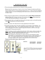
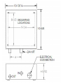
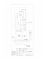
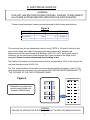
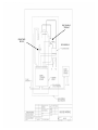
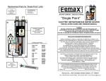
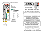
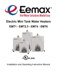
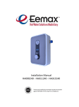
EEMAX
HOME ADVANTAGE
ELECTRIC INSTANTANEOUS WATER HEATER
INSTALLATION GUIDE AND OWNERS MANUAL
MODELS COVERED:- SS015240TC
208-240V
SS019240TC 208-240V
WARNING
READ THE GENERAL SAFETY SECTION BEGINNING ON THE INSIDE COVER
AND THEN THIS ENTIRE MANUAL BEFORE INSTALLING OR OPERATING THIS
WATER HEATER. IF YOU DON’T FOLLOW THE SAFETY RULES, THE UNIT WILL
NOT OPERATE PROPERLY AND IT COULD CAUSE DEATH, SERIOUS BODILY
INJURY AND/OR PROPERTY DAMAGE. READ ALSO THE ENCLOSED
WARRANTY CARD. WARRANTY OF THIS WATER HEATER WILL DEPEND ON
PROPER INSTALLATION AND OPERATION. THE WARRANTY SHALL BE VOID IF
THE DESIGN HAS BEEN ALTERED IN ANY WAY WHATSOEVER. THE
MANUFACTURER OF THIS HEATER WILL NOT BE LIABLE FOR ANY DAMAGES
BECAUSE OF FAILURE TO COMPLY WITH THE INSTALLATION AND
OPERATING INSTRUCTIONS OUTLINED ON THE FOLLOWING PAGES.
THIS UNIT HAS MULTIPLE POWER SOURCES. ENSURE TO DISCONNECT ALL POWER
SUPPLIES BEFORE SERVICING.
THE INSTALLATION MUST CONFORM WITH THE INSTRUCTIONS IN THIS
MANUAL; ELECTRIC COMPANY RULES; AND THE LOCAL CODES, OR IN
THE ABSENCE OF LOCAL CODES, WITH THE LATEST EDITION OF THE
NATIONAL ELECTRICAL CODE. THIS PUBLICATION IS AVAILABLE FROM
YOUR LOCAL GOVERNMENT OR PUBLIC LIBRARY OR ELECTRIC COMPANY
IF YOU REQUIRE ANY HELP OR HAVE ANY QUESTIONS RELATING TO THE
INSTALLATION OR PERFORMANCE OF THIS HEATER, PLEASE CALL OUR
TECHNICAL SERVICE DEPARTMENT TOLL FREE : 1-800-543-6163.
HAVE THE INFORMATION LISTED BELOW BEFORE CALLING :
SERIAL NO.
MODEL NO.
INSTALLATION DATE
1
GENERAL SAFETY
The “Eemax Home Advantage” heater is specifically designed to take in hot or cold water and
heat it to temperatures suitable for normal domestic usage up to a maximum of 140 F(60 C).
To obtain optimum performance and energy savings, the unit should be located as
near as possible to the point of use. “Thermostatic” models indicated by the letters TC after
the model number, these models and only these, can be fed with pre-heated water and be
used to boost temperature
The unit is supplied with ¾’’ quick connect/disconnect type fittings. Follow the instructions
supplied by the manufacturer of the fittings that are supplied with this manual.
When removing and re-installing the cover make sure to use the ground screw provided. There
are a total of 5 screws that affix the cover to the unit. If you are missing any call technical
support at 1-800-543-6163.
Also, ensure that the pipes are clear of installation debris before fitting the heater.
WARNING
FAILURE TO GROUND THE SYSTEM MAY RESULT IN DEATH OR SERIOUS INJURY.
THIS UNIT HAS MULTIPLE POWER SOURCES. ENSURE TO DISCONNECT ALL POWER
SUPPLIES BEFORE SERVICING
THIS HEATER MUST HAVE TWO DEDICATED INDEPENDENT 240V, 220V
or 208V CIRCUITS, USING CORRECTLY RATED WIRES AND CIRCUIT
BREAKERS. PER UL 499, 18.4 THE RATING OF THE BRANCH-CIRCUIT
OVERCURRENT PROTECTIVE DEVICE SHALL BE 150% OF THE RATING
OF THE PRODUCT. DO NOT USE SPACE SAVING BREAKERS.
WARNING
IMPROPER INSTALLATION, ADJUSTMENT, ALTERATION, SERVICE OR MAINTENANCE
CAN CAUSE DEATH, SERIOUS BODILY INJURY OR PROPERTY DAMAGE. REFER TO
THIS MANUAL FOR ASSISTANCE OR CONSULT THE LOCAL ELECTRIC UTILITY FOR
FURTHER INFORMATION.
WARNING
WATER HEATERS EQUIPPED FOR ONE VOLTAGE ONLY: THIS WATER HEATER MAY BE
EQUIPPED FOR ONE VOLTAGE TYPE ONLY: CHECK THE RATING PLATE ON THE FRONT
COVER OF UNIT FOR THE CORRECT VOLTAGE. DO NOT USE THIS WATER HEATER WITH
ANY OTHER VOLTAGE OTHER THAN THE ONE SHOWN ON THE MODEL RATING PLATE.
FAILURE TO USE THE CORRECT VOLTAGE CAN CAUSE PROBLEMS WHICH CAN RESULT
IN DEATH, SERIOUS BODILY INJURY, OR PROPERTY DAMAGE. IF YOU HAVE ANY
QUESTIONS OR DOUBTS CONSULT EEMAX OR YOUR ELECTRIC COMPANY.
WARNING
HAZARD OF ELECTRICAL SHOCK! BEFORE REMOVING THE COVER OR SERVICING THE
WATER HEATER, MAKE SURE THE ELECTRICAL SUPPLY TO THE WATER HEATER IS
TURNED “OFF”. FAILURE TO DO THIS COULD RESULT IN DEATH, SERIOUS BODILY INJURY,
OR PROPERTY DAMAGE. NOTE: UNIT HAS MULTIPLE ELECTRICAL CONNECTIONS.
2
I. MOUNTING THE UNIT
1) The unit should be mounted as close to the point of use as possible.
Do not install the heater above a faucet or “point of use” because the siphoning effect may
drain the heater which can cause premature element burn out. If the unit must be installed at
a higher elevation, you must install spring loaded check valves on both the inlet and outlet of
the water heater.
2) This unit must only be mounted in a vertical position with the water fittings located at the
bottom of the unit. Mounting other than in the vertical position WILL cause element burn
out and cause permanent damage to the water heater.
3) The cold water inlet is on the right hand side and the hot water outlet is on the left hand side.
Under NO circumstances can these be reversed.
4) Leave a minimum of 8” above the unit for easy replacement of the element.
5) The heater should be fixed to the wall using all four mounting holes of the backplate. Unit
weight is approximately 12lbs. Use an appropriate fastener for this weight. For the unit to
be mounted against hollow walls, suggest using steel wall anchors, with the correct grip
range and #10-32 screw size minimum.
NOTE: The heater should be installed below the level of all hot water outlets serviced by this
heater. Otherwise install spring loaded check valves on both the inlet and outlet.
NOTE: PRESSURE AND TEMPERATURE RELIEF VALVE
These units are not required by UL to have a Pressure and Temperature Relief
Valve (PTRV). You should check with local codes to find out if one is required in your
area. If local codes require the use of a temperature and pressure relief valve it
should be installed on the outlet hot water pipe before the outlet ball valve.
Showers and the whole house, cabin or condo
Lavatory
MODELS:
Shower
SS015240TC 208-240V
SS019240TC 208-240V
Kitchen
About 0.70-3.0 GPM at showering temperature.
Best used when operating one or two outlets
at a time.
Eemax
Hot outlet
Cold inlet
3
MINIMUM - 8” CLEARANCE ABOVE UNIT
serial #
MOUNTING
HOLES
LUG
TERMINALS
AT RELAYS
L1
L2
C/B #4
ELECTRICAL
HOOK-UP
240/208 V
L1
L2
C/B #3
GROUND
LUGS
Use pre-install quick connect water
connections
Figure 1A
4
To 2 Independent circuit breakers, properly
rated per UL499 18.4, 150% of the products
rating.
II. PLUMBING HOOK-UP
1) The unit is supplied with ¾’’ NPT fittings and pre-fitted quick connect/disconnect fittings,
Use this if you prefer. You may remove the shark bite type fitting and use the standard
¾’’ NPT fitting if you desire. Remove the shark bite type fitting while the unit is NOT attached
to the wall.
2) Take care to ensure that the pipes are correctly aligned with the inlet and outlet bosses
in order to avoid excessive stress on the heater body molding.
NOTE: When soldering pipe joints remove heater from the wall. Serious damage can occur
if any soldering is done while pipes are connected to the heater.
When tighten the fittings make sure to secure the fitting inside the heater to make
a tight connection.
Run water through the supply pipe to remove all debris from the pipe before connecting
the heater. Failure to do so could cause damage to the flow switch.
3) Install isolating valves (full flow ball valve type) on both inlet and outlet pipes. This allows unit
to be isolated for maintenance purposes. (Fig. 1B)
4) When all plumbing is complete, fully check the system for water leaks at all the plumbing
connections. If a leak is present take corrective action. Fully open both inlet and outlet
BALL VALVES.
Run all the hot water outlets fed by this heater one at a time, for a minute or two, until the water
flow is continuous, free from “gulping” and from all visible air pockets.
Figure 3
HOT OUTLET
¾’’ NPT
with PRE-FITTED QUICK
CONNECT/DISCONNECT
FITTINGS
DO NOT SOLDER
4.0”
COLD INLET
¾’’ NPT
With PRE-FITTED QUICK
CONNECT/DISCONNECT
FITTINGS
DO NOT SOLDER
NOTE:
ALL MOUNTING AND PLUMBING MUST BE COMPLETE BEFORE YOU
PROCEED WITH ELECTRICAL HOOK-UP.
TEST THE INSTALLATION FOR LEAKS BEFORE CONNECTING THE
ELECTRICAL SUPPLY.
6
III. ELECTRICAL HOOK-UP
WARNING
THIS UNIT HAS MULTIPLE POWER SUPPLIES. ENSURE TO DISCONNECT
ALL POWER SUPPLIES BEFORE SERVICING THE WATER HEATER.
“Eemax Home Advantage” heaters are manufactured to the following specifications:
Figure 4
M O DE L TY P E
S S 015240TC
S S 019240TC
V oltage
k W output
240V
240V
A M P E RA G E
15 2 x 32 A M P S
19 2 x 39 A M P S
This unit must have its own independent circuits, using 2 SETS of UL listed 2 conductor and
ground core copper wire cable of the appropriate size protected by 2 separate and
independent correctly rated Double Pole Breakers. (208, 220, 240 V, see Figures 4 and 5).
Wire entry into the unit must be made through the 4 holes provided in the flange on the
backplate. Ensure to check national and local building codes.
The Rating of the branch-circuit overcurrent protective device shall be 150% of the rating of the
unit (see chart above) per UL 499 18.4.
The “live” wires should be connected to the slots in the terminal block marked L1 and L2. The
ground lead must be connected to the slot marked GND. GROUND MUST BE BROUGHT TO
THE “GROUND” AT THE CIRCUIT BREAKER PANEL.
Figure 5
ON
OFF
ON
OFF
ON
OFF
2 Separate and independent
correctly rated Double pole
breakers (240/208 Volts)
ON
OFF
Circuit Breaker Panel
DANGER
FAILURE TO GROUND THE SYSTEM MAY RESULT IN DEATH OR SERIOUS INJURY.
7
IV COMMISSIONING YOUR HEATER
IMPORTANT
BEFORE SWITCHING “ON” THE POWER AT THE MAIN CIRCUIT BREAKER PANEL
MAKE SURE THAT THE HOT WATER CIRCUIT IS FREE OF AIR POCKETS OR ELSE
PREMATURE FAILURE OF THE ELEMENT WILL OCCUR. TO DO THIS OPEN ALL HOT
WATER OUTLETS ONE AT A TIME FOR A MINUTE OR TWO UNTIL THE WATER FLOW
IS CONTINUOUS AND FREE FROM “GULPING” AND FREE FROM VISIBLE AIR POCKETS.
1) Open fully both inlet and outlet valves at the heater.
2) Open any hot water outlet in the system. If the outlet is a “single lever” mixer type turn to the
hottest position. Run for one minute to clear all the air from the system.
3) Slowly close OUTLET ball valve until the water flow from the faucet just starts to reduce.
NOTE: This process has two effects. One, any air in the system will be purged out. Two, the
heater units will be pressurized at the supply pressure. This will prevent the elements free from
air pockets while energized
4) At this point you may energize the hot water heater. Unit has 2 separate circuit breakers.
Once energized the Thermostatic control touch pad display on the front cover will
illuminate. This is where and when you will program your desired temperature.
Note: Control boards have a 3 second delay for the time the flow requirement is reached and
activation.
NOTE
Unit will display the programmed temperature, not the actual outlet temperature
140 F
F/C
Increase temperature
Decrease temperature
Fahrenheit / Celsius
To trouble shoot the display board, shut off power to the unit. Press and hold all three buttons.
While buttons are depressed, re-energize the unit. If display board is working properly, the word
“Yes” will display. If the board has a fault it will display “No”. Call technical support for a
replacement.
8
TROUBLESHOOTING
SYMPTOM “A”: NO HEAT, INDICATOR LIGHT OFF
1) ELECTRIC SUPPLY IS OFF
Turn on the TWO main circuit breakers. Ensure the breakers are properly connected to the
relay. L1/L2 from one breaker must correspond with the same relay. You must be able to get
240V across each relay when powered up independently. Do not use space saving breakers.
2) NO OR LOW WATER FLOW
Ensure that the minimum flow rate to switch on your heater is met. “TC” Models minimum
flow rate = 0.70 gallons per minute. Also check that the inlet filter screen is clear from any
debris. This is located in the brass inlet boss.
3) WATER CONNECTIONS ARE REVERSED
Cold water inlet = right side, hot water outlet = left side.
4) ELEMENT BURNED OUT
TURN OFF THE TWO MAIN CIRCUIT BREAKERS!
Using an ohmmeter test the resistance of the heating element
across the two threaded termination rods on top of the element.
The resistance reading should be roughly 5.0 ohms. If the resistance
is much greater than this value, call Eemax for a replacement element.
5) ECO TRIPPED (High Limit Thermostat)
TURN OFF THE TWO MAIN CIRCUIT BREAKERS!
Reset by pushing in red button on each heater module. If the Eco was tripped it will re-engage.
SYMPTOM “B”: NO HEAT OR LOW TEMPERATURE WITH INDICATOR LIGHT ON
1) WATER FLOW TOO HIGH
Reduce the water flow by using an outlet ball valve. See specifacation sheet for temperature rise at
various flow rates.
2) INCORRECT POWER SUPPLY
Make sure that the unit is connected to the voltage supply specified on the rating label on the front
cover of the unit and no other.
3) ELEMENT BURNED OUT
TURN OFF THE TWO MAIN CIRCUIT BREAKERS!
Repeat the steps from paragraph 4 above.
4) ECO TRIPPED (High Limit Thermostat)
TURN OFF THE TWO MAIN CIRCUIT BREAKERS!
Reset by pushing in red button on each heater module.
10
EX1049-1
TRIAC
EX278C
ECO
EX1050-1