1
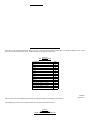
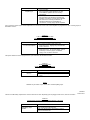
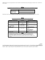
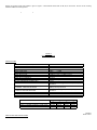
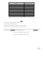
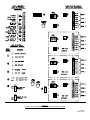
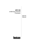
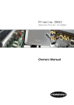
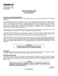
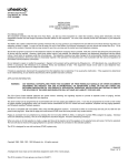
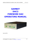
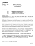
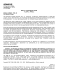
273 Branchport Avenue
Long Branch, N.J. 07740
(908) 222-6880
INSTALLATION INSTRUCTIONS
MODEL ZC-312
MODULAR ZONE CONTROL
(3 ZONES EXPANDABLE TO 12 ZONES)
- AND MODEL ZEM-3
ZONE EXPANSION MODULE
(3 ZONES)
FCC REGULATIONS
This equipment complies with Part 68 of the FCC Rules. On the top of this equipment is a label that contains, among other information, the FCC
Registration Number and the Ringer Equivalence Number (REN) for this equipment. You must, upon request provide this information to your telephone
company.
The REN is also useful to determine the quantity of devices that you may connect to your telephone line and still have all of those devices ring when your
telephone number is called. In most, but not all areas, the sum of the REN's of all devices connected to one line should not exceed five (5.0). To be
certain of the number of devices that you may connect to your line, you may want to contact your local telephone company.
Should the equipment cause harm to the telephone network, the telephone company shall, if possible, notify the customer that temporary discontinuance
of service may be required. However, where prior written notice is not possible, the telephone company may temporarily discontinue service without
notice, if such action is necessary under the circumstances. The telephone company may make changes in its communication facilities, equipment and
operations procedures, where such action is reasonably required in the operation of its business and is not inconsistent with the rules and regulations of
the Federal Communications Commission.
Do not attempt to repair or modify this equipment. Repairs to this product will be performed by Wheelock Inc. 273 Branchport Ave, Long Branch, NJ
07740 in accordance with Wheelock Inc.'s published Terms and Conditions of Sale. This equipment should not be used on coin telephone lines.
Connection to party line service is subject to state tariffs.
If trouble is experienced, disconnect this equipment from the telephone line to determine if it is causing the malfunction. If the equipment is determined
to be malfunctioning, its use shall be discontinued until the problem has been corrected.
APPLICATION INFORMATION
WARNING:
ANY MATERIAL EXTRAPOLATED FROM THIS DOCUMENT OR FROM WHEELOCK MANUALS OR OTHER DOCUMENTS
DESCRIBING THE PRODUCT FOR USE IN PROMOTIONAL OR ADVERTISING CLAIMS, OR FOR ANY OTHER USE,
INCLUDING DESCRIPTION OF THE PRODUCT'S APPLICATION, OPERATION, INSTALLATION AND TESTING IS USED AT
THE SOLE RISK OF THE USER AND WHEELOCK WILL NOT HAVE ANY LIABILITY FOR SUCH USE.
The ZC-312 is an expandable Zone Control that performs the central control, switching and signaling required to provide selective zone paging, zone
group paging, all call, talkback, background music mute, and page alert tone signaling. The ZC-312 provides 3 separate zones of paging, and can be
expanded to 12 zones by installing up to 3 ZEM-3 Zone Expansion Modules. Each ZEM-3 provides a zone group consisting of 3 zones. Each ZEM-3
provides a background music input for its 3 zone group.
Containing its own (centralized) talkback control circuit, the ZC-312 can be programmed to accommodate both one-way and talkback paging zones. It
can also be programmed to be used with a wide variety of system amplifier configurations which can include various combinations of 25V/70V central
and zone amplifiers and amplified one-way paging speakers.
Copyright 1989, 1990, 1991, 1992, 1993 Wheelock Inc. All rights reserved.
P81982 K
Sheet 1 of 21
The ZC-312 is compatible with most EKSU, KSU (1A2), and PBX telephone systems. It connects to either an unused loop start CO port or a 600 ohm
low power audio page port. When connected to an unused CO port, both DTMF and rotary (pulse) dial telephones may be used to operate the ZC-312.
When connected to a page port, the page port must transmit DTMF tones and provide a dry contact closure. The ZC-312 can also be used in "Ring
Start" applications (CO/Centrex, Station Level), when used with the Wheelock TPI-100 Telephone Paging Interface.
Paging is accessed from any telephone by pressing the CO line button (EKSU & KSU), or dialing the number assigned to paging. Twelve (12) individual
zones are selected by dialing 01 thru 12. All Call is selected by dialing 00. The four (4) zone groups are selected for group paging, by dialing 21 thru 24.
When any zone, zone group, or all call selection is made, a page alert tone will be heard at all the speakers in the selected zone, zone group, or all
zones (if all call is selected). The tone will also be heard at the paging telephone to provide verification of connection to the selected speakers.
The ZC-312 provides one zone group (3 zones) and can be expanded to 4 zone groups (12 zones), by adding up to 3 plug-in ZEM-3 zone expansion
modules as shown in Chart 1 and Figure 1.
CHART 1
ZONE GROUPS
GROUP
1
2
3
4
Z0NES
1,2,3
4,5,6
7,8,9
10,11,12
QTY. OF ZEM-3
0
1
2
3
INTERFACE INFORMATION:
The ZC-312 can be connected directly to:
A.
A telephone for stand alone paging.
B.
A telephone system's unused CO line/trunk port.
C.
A telephone system's 600 ohm audio page port (See Figure 12, page 19).
Using a Wheelock TPI -100 Telephone Paging Interface, the ZC-312 can be interfaced to ring start telephone paging applications such as:
A.
An analog station level line.
B.
A CO/Centrex line.
(See Figure 13 page 19)
P81982 K
Sheet 2 of 21
Figure 1 shows the ZC-312 PC Board which includes built-in zone group 1 (Zones 1, 2, & 3), and illustrates the positions for the optional ZEM-3 Zone
Expansion Modules.
FIGURE 1
ZC-312 PC BOARD AND ZEM-3 POSITIONS
Each zone may be accessed individually by dialing 01 thru 12. All zones can be accessed simultaneously for an all call by dialing 00. Each 3 zone
group can be accessed by dialing 21 thru 24. Chart 2 illustrates the two digit dial access codes.
CHART 2
DIAL ACCESS CODES
TO ACCESS
All Zones (All Call)
Zone 1
Zone 2
Zone 3
Zone 4
Zone 5
Zone 6
Zone 7
Zone 8
Zone 9
Zone 10
Zone 11
Zone 12
Zone Group 1 (Zones 1, 2 & 3)
Zone Group 2 (Zones 4, 5 & 6)
Zone Group 3 (Zones 7, 8 & 9)
Zone Group 4 (Zones 10, 11 & 12)
DIAL
00
01
02
03
04
05
06
07
08
09
10
11
12
21
22
23
24
P81982 K
Sheet 3 of 21
Each zone group can be individually programmed with group selector switches for the following group functions.
The amplifier type (central or zone) is programmed for each zone group as described in Chart 3.
CHART 3
AMPLIFIER TYPE
GROUP PROGRAMMABLE FUNCTION
GROUP FUNCTION
CHOICES - PER GROUP
1. Central Amplifier:
25V or 70V audio output switched to one-way
and/or talkback speakers with line matching
transformers.
2. Zone Amplifier:
600 ohm audio input switched to separate zone
amplifiers connected to one-way paging speakers
with 25V/70V line matching transformers; or
switched to PRM-150 line preamplifiers or
connected to one-way paging speaker amplifiers.
Amplifier Type
If any of the zone groups require central amplification, then the choice of one or two central amplifiers is programmed for each of those groups, as
described in Chart 4.
CHART 4
1 OR 2 CENTRAL AMPLIFIERS
GROUP PROGRAMMABLE FUNCTION
GROUP FUNCTION
1 or 2 Central Amplifiers
CHOICES - PER GROUP
1. One central amplifier for both paging and
background music. Paging in any zone will mute
music in all zones.
2. Two central amplifiers, one for paging and one for
background music. For one-way paging, music is
muted only in the zone paged. For talkback
paging, music is muted in all zones.
The speech direction function is programmed on a per zone basis, as described in Chart 5.
CHART 5
SPEECH DIRECTION
ZONE PROGRAMMABLE FUNCTION
FUNCTION
Speech
Direction
CHOICES - PER ZONE
1. One-way paging.
2. Talkback (two-way communication with hands-free
reply).
NOTE
Talkback may be chosen only for zones within central amplifier groups.
P81982 K
Sheet 4 of 21
The ZC-312's talk battery output function can be turned "ON" or "OFF" depending upon the paging access source, as shown in Chart 6.
CHART 6
TALK BATTERY OUTPUT SYSTEM PROGRAMMABLE FUNCTION
FUNCTION
Talk Battery output
ON/OFF
CHOICES FOR SYSTEM
"ON" for stand alone telephone, unused CO line/trunk
port, and 600 ohm audio page port..
"OFF" with Wheelock TPI-100 Interface for station
level, CO or Centrex line.
Additionally, the ZC-312 can be programmed for use with a Wheelock TPI-100 Interface which produces paging from a Station Level, or Centrex line, as
shown in Chart 7.
CHART 7
TPI-100 INTERFACE FOR STATION LEVEL, CO, OR CENTREX PAGING SYSTEM PROGRAMMABLE FUNCTION
FUNCTION
Station level, CO or
Centrex line paging
(Wheelock TPI-100
Interface is required).
CHOICES FOR SYSTEM
"LO" with Wheelock TPI-100 Interface.
"HI" without Wheelock TPI-100 Interface.
Depending upon system amplifier configuration, the amplifier functions and background music mute operation will vary, as shown in Chart 8.
CHART 8
AMPLIFIER CONFIGURATIONS, FUNCTIONS, AND MUSIC MUTE OPERATION
AMPLIFIER CONFIGURATION
(A) One (1) Central Amplifier
FUNCTION
Paging & Music
(B) Two (2) Central Amplifiers
One for Paging
and
One for Music
(C) Zone Amplifiers,
Line Preamplifiers
Speaker Amplifiers
(D) Mixed
(A) & (C) Above
Paging & Music
Paging & Music
(E) Mixed
(B) & (C) Above
Paging & Music
MUSIC MUTE OPERATION
Paging any zone will mute music in
all zones.
Music is muted only in the paged
zone(s).
Music is muted only in the paged
zone(s)
1. Central Amplifier Zones:
Paging mutes music in all
zones.
2. Zone Amplifier Zones:
Music is muted only in
the paged zone(s).
Music is muted only in the paged
zone(s).
NOTES
1. The talkback function is centrally controlled in the ZC-312, and can be selected per Zone for
Configurations (A) and (B), as well as the (A) and (B) segments of mixed systems (D) and (E).
2. Mixed amplifier configurations (D) and (E) cannot be applied within the same zone group.
3. When 2 central amplifiers are used, music will be muted in All Zones only when a Talkback Zone is
accessed.
P81982 K
Sheet 5 of 21
The following application diagrams show the seven basic system configurations of the ZC-312 and its companion ZEM-3 Zone Expansion Modules. All
of these configurations are possible with the appropriate programming switch selections. Figures 2, 3, 4, and 5 are typical configurations using central
amplifiers. Figure 6 is a typical configuration using amplified speakers. Figures 7 and 8 are typical configurations using zone amplifiers.
FIGURE 2
ONE CENTRAL AMPLIFIER WHICH HAS MUSIC MUTE,
PAGE INPUT AND MUSIC INPUT
(ONE-WAY PAGING AND/OR TALKBACK)
In this application, the one central amplifier for both paging and background music has music muting and separate inputs (volume controls) for paging
and music. The system uses speakers with built-in line matching transformers for both one-way paging, and paging with talkback.
NOTE
1.
If the central amplifier does not provide music mute, then the background music source is connected as shown in Figure 3.
2.
In systems with talkback paging, install one background music source only as shown. DO NOT connect background music source directly to zone
group music inputs.
P81982 K
Sheet 6 of 21
FIGURE 3
ONE CENTRAL AMPLIFIER
WHICH DOES NOT HAVE MUSIC MUTE,
AND WHICH HAS ONLY ONE INPUT
(ONE-WAY PAGING AND/OR TALKBACK)
In this application, the one central amplifier for both paging and background music does not provide music muting, and has only one input (one, or no
volume control). The system uses speakers with built-in line matching transformers for both one-way paging, and paging with talkback.
NOTE
1.
If the background music source has no volume control, then the optional PRM-150 must be connected between the background music source and
the ZC-312 MUSIC input, as shown.
2.
In systems with talkback paging, install one background music source only as shown. DO NOT connect background music source directly to zone
group music inputs.
P81982 K
Sheet 7 of 21
FIGURE 4
TWO CENTRAL AMPLIFIERS,
ONE FOR PAGING AND ONE
FOR BACKGROUND MUSIC
(ONE-WAY PAGING ONLY)
In this application, two central amplifiers are used, one for paging and one for background music. The system uses speakers with built-in line matching
transformers for one-way paging.
NOTES
1.
If both the music central amplifier and the background music source have no volume controls, then a PRM-150 must be connected between the
background music source output and the music central amplifiers input.
2.
Different music sources, each with its associated music amplifier (and optional PRM-150 as required) can be used for different zone groups.
P81982 K
Sheet 8 of 21
FIGURE 5
TWO CENTRAL AMPLIFIERS,
ONE FOR PAGING AND ONE
FOR BACKGROUND MUSIC
(ONE-WAY AND/OR TALKBACK PAGING)
In this application, two central amplifiers are used, one for paging and one for background music. The system uses speakers with built-in line matching
transformers for both one-way paging, and paging with talkback.
NOTES
1.
If both the music central amplifier and the background music source have no volume controls, then a PRM-150 must be connected between the
background music source output and the music central amplifiers input.
2.
In systems with talkback paging, install one background music source only as shown. DO NOT connect background music source directly to zone
group music inputs.
P81982 K
Sheet 9 of 21
FIGURE 6
AMPLIFIED SPEAKERS
(ONE-WAY PAGING)
In this application, amplified speakers are used for one-way paging and for background music. A PRM-150 preamplifier is used with the background
music source.
NOTE
One music source can be used for all zone groups, or different music sources can be used for different zone groups.
P81982 K
Sheet 10 of 21
FIGURE 7
ZONE AMPLIFIERS
WHICH HAVE MUSIC MUTE,
PAGE INPUTS AND MUSIC INPUTS
(ONE-WAY PAGING)
In this application, the zone amplifiers for both one-way paging and background music have music muting, and separate inputs (volume controls) for
paging and music. The system uses speakers with line matching transformers.
NOTE
One music source may be used for all zones, or different music sources can be used for different zones.
P81982 K
Sheet 11 of 21
FIGURE 8
ZONE AMPLIFIERS
WHICH DO NOT HAVE MUSIC MUTE,
AND WHICH HAVE ONE INPUT
(ONE-WAY PAGING)
In this application, the zone amplifiers for both one-way paging and background music do not provide music muting, and have only one input (with or
without volume control). The system uses speakers with line matching transformers.
NOTE
One music source can be used for all zone groups, or different music sources can be used for different zone groups.
P81982 K
Sheet 12 of 21
Existing system renovations and expansions often require different amplifier configurations in different zone groups. For example, an existing central
amplifier paging system may be zoned, and then expanded by adding amplified speakers or zone amplifiers. With the appropriate programming switch
selections, the following are some examples of mixed system possibilities.
A.
B.
C.
D.
E.
F.
G.
H.
I.
J.
K.
L.
FIGURE 2 AND FIGURE 6
FIGURE 2 AND FIGURE 7
FIGURE 2 AND FIGURE 8
FIGURE 3 AND FIGURE 6
FIGURE 3 AND FIGURE 7
FIGURE 3 AND FIGURE 8
FIGURE 4 AND FIGURE 6
FIGURE 4 AND FIGURE 7
FIGURE 4 AND FIGURE 8
FIGURE 5 AND FIGURE 6
FIGURE 5 AND FIGURE 7
FIGURE 5 AND FIGURE 8
In mixed systems, the different amplifier configurations must be installed in different zone groups.
configurations within the same zone group.
It is not possible to mix different amplifier
Maximum amplifier and speaker capacity for each zone group and the total system is shown in Chart 9.
CHART 9: MAXIMUM AMPLIFIER AND SPEAKER CAPABILITY
AMPLIFIER CONFIGURATION
CENTRAL AMPLIFIER(S)
ZONE AMPLIFIERS OR
SPEAKER-AMPLIFIERS
MAXIMUM CAPACITY
TOTAL SYSTEM
EACH ZONE GROUP
150W @ 70V
70W @ 70V
100W @ 25V
25W @ 25V
(SEE NOTE 1)
150 AMPLIFIERS
75 AMPLIFIER
INPUTS
INPUTS
(SEE NOTE 2)
NOTES
1.
The Zone Control can switch an audio input from a central amplifier of up to 150W @ 70V, or 100W @ 25V. This TOTAL SYSTEM audio input
can be distributed to up to 4 zone groups, provided no single zone group exceeds:
(A) 70W @ 70V, leaving 80W for the remaining 3 groups.
- or (B) 25W @ 25V, leaving 75W for the remaining 3 groups.
2.
The Zone Control can switch its preamplifier audio output to the 600 ohm inputs of up to 150 zone amplifiers or speaker-amplifiers. This TOTAL
SYSTEM audio output can be distributed to up to 12 zones, provided no SINGLE ZONE exceeds 25 amplifier inputs, which would leave 125
amplifier inputs for the remaining 11 zones.
P81982 K
Sheet 13 of 21
MOUNTING INSTRUCTIONS:
The ZC-312 is designed for indoor surface wall mounting near the telephone system. Remove the ZC-312 cover from the base (containing the PC Board
assembly) by removing the screw on each side of the unit. Two keyholes and two circular holes are provided in the base for easy installation. A
diagram for mounting screw hole locations is given in Figure 9. Recommended screw sizes are #6, #8, or #10 screws. Be sure to use mounting
hardware suitable for mounting surface.
FIGURE 9
MOUNTING DIAGRAM
SPECIFICATIONS
SUPPLY VOLTAGE (NOMINAL)
SUPPLY VOLTAGE RANGE
ALERT TONE FREQUENCY
ALERT TONE DURATION
ALERT TONE LEVEL
TIP AND RING INPUT LEVEL
MUSIC INPUT LEVEL
TIP AND RING INPUT IMPEDANCE
MUSIC INPUT IMPEDANCE
MAX. OUTPUT LEVEL TO AMPLIFIER 1
OUTPUT IMPEDANCE TO AMPLIFIER 1
MAX. INPUT LEVEL FROM AMPLIFIER 1
AUDIO OUTPUT LEVEL (MAX. - PER ZONE)
- SPEAKER - AMPLIFIER SELECTED
AUDIO OUTPUT LEVEL (MAX. - PER ZONE GROUP)
- CENTRAL-AMPLIFIER SELECTED
OPERATING TEMPERATURE RANGE
OPERATING HUMIDITY RANGE
OFF-HOOK DETECTION SENSITIVITY
SUPPLY CURRENT (IDLE-BGM)
SUPPLY CURRENT (NOMINAL-1 ZONE PAGE)
SUPPLY CURRENT (MAXIMUM-ALL CALL)
-24VDC
-21.6VDC to -26.4VDC
1100Hz +/-10%
420m sec. +/-10%
-4dBM
+/-3dBM
-15dBM (0.1Vrms) to +10dBM (2.4Vrms)
-15dBM (0.1Vrms) to +10dBM (2.4Vrms)
600 ohms
600 ohms
0dBM (0.78Vrms)
4 ohms
100W @ 25V or 150W @ 70V (central amplifier output)
See Note 2
0dBM (0.78Vrms), 600 Ohms
25W @ 25V or 70W @ 70V (central amp. output)
See Note 2
0 to 55 degrees C
0 to 85% RH
1850 Ohms DC Resistance (1400 to 2200 Ohms)
QTY OF ZEM-3 MODULES IN SYSTEM
0
1
2
3
77 mA
77 mA
77 mA
77 mA
177 mA
302 mA
227 mA
252 mA
227 mA
327 mA
427 mA
527 mA
P81982 K
Sheet 14 of 21
ZONE ACCESS AND DIALING CODES
ZONE CONTROL ACCESS
(See Note 1)
PRESS CO LINE BUTTON, OR DIAL
NUMBER ASSIGNED TO PAGE.
DIAL 01
DIAL 02
DIAL 03
DIAL 04
DIAL 05
DIAL 06
DIAL 07
DIAL 08
DIAL 09
DIAL 10
DIAL 11
DIAL 12
DIAL 21
DIAL 22
DIAL 23
DIAL 24
DIAL 00
PAGE ZONE 1
PAGE ZONE 2
PAGE ZONE 3
PAGE ZONE 4
PAGE ZONE 5
PAGE ZONE 6
PAGE ZONE 7
PAGE ZONE 8
PAGE ZONE 9
PAGE ZONE 10
PAGE ZONE 11
PAGE ZONE 12
PAGE ZONE GROUP 1 (ZONES 1, 2 & 3)
PAGE ZONE GROUP 2 (ZONES 4, 5 & 6)
PAGE ZONE GROUP 3 (ZONES 7, 8 & 9)
PAGE ZONE GROUP 4 (ZONES 10, 11 & 12)
PAGE ALL ZONES (ALL CALL)
NOTES
1.
Press CO line button: For EKSU & KSU (1A2) key telephone systems.
Dial number assigned: For PBX telephone systems.
Dial telephone number: For CO/Centrex Line (Requires TPI-100 Interface, see Figure 13).
Dial extension number: For analog station level (Requires TPI-100 interface, see Figure 13).
2.
The ZC-312 can switch a TOTAL SYSTEM central amplifier audio input of up to 150W @ 70V, or 100W @ 25V. The TOTAL SYSTEM audio input
can be distributed to up to 4 zone groups, provided no single zone group exceeds:
(A) 70W @ 70V, leaving 80W for the remaining 3 zone groups.
-OR(B) 25W @ 25V, leaving 75W for the remaining 3 zone groups.
P81982 K
Sheet 15 of 21
FIGURE 10
SIMPLIFIED SINGLE LINE BLOCK DIAGRAM
WIRING INSTRUCTIONS (SEE FIGURE 11)
1.
2.
3.
4.
5.
6.
7.
8.
Make sure 24VDC power supply is disconnected from the 115VAC power source.
Connect tip and ring from:
A. Stand along telephone, or
B. Telephone system's unused CO line/trunk port, or
C. Telephone system's 600 ohm, audio page port (See Figure 12), or
D. Wheelock TPI-100 Interface for CO/Centrex line or analog station level line (See Figure 13),To TB1 terminals 4 and 3 respectively, on
the
ZC-312.
Connect the background music source to TB1, terminals 9 and 10, on the ZC-312.
Connect the 24VDC power supply to the (-)24V and GND(+) terminals on TB1, terminals 2 and 1 respectively.
Connect the zone amplifier, speaker amplifiers, or speakers with transformers to the audio pair for zones 1 thru 12 on TB2 of the ZC-312 and TB1
of each ZEM-3 module as required.
If one Central Amplifier is used for paging and background music:
A. Connect the input of central amplifier to AMP1 OUT, terminals 11 and 12 of TB1 on the ZC-312. Connect the output of central
amplifier to AMP1 IN, terminals 13 and 14 of TB1 on the ZC-312.
B. Connect the output of central amplifier to MUSIC, terminals 7 and 8 of TB2 on ZC-312 and TB1 on ZEM-3 modules, as required.
If separate central amplifiers are used, one for paging and one or more for background music:
A. Connect paging amplifier as described in 6A, above.
B. Connect output of background music amplifier(s) as described in 6B, above.
Connect the 24VDC power supply to the 115VAC source.
NOTE
When only one central amplifier is used, background music will be muted in all zones when a page is in progress. When separate central amplifiers are
used, background music will be muted in only the paged zone.
P81982 K
Sheet 16 of 21
PROGRAMMING INSTRUCTIONS (SEE FIGURE 11 OR INSIDE OF ZC-312 COVER)
1.
Set the "Zone Amplifier/Central Amplifier" select switches for each group as required. See switch symbol 1 . If a group is using a zone amplifier
or speaker amplifier, then that group's switch should be in the down position. If a group is using a central amplifier, then that group's switch should
be in the up position.
2.
Set the "Central Amplifier" select switch for each group, as required. See switch symbol 2 . If one central amplifier is used for both paging and
background music, then the switch should be in the down position. If two or more central amplifiers are used, one for paging and one or more for
background music, then the switch should be in the up position. If central amplifiers are not used, then the switch should be in the up position.
3.
Set the "One-Way/Talkback" select switches for each zone as required. See Switch symbol 3 . If a zone is to have talkback paging, then that
zone's switch should be in the up position. If a zone is to have one-way paging, then that zone's switch should be in the down position.
NOTE: All zones in groups using (selected for) zone amplifiers or speaker amplifiers are one-way paging zones. Hence, the individual zone
switches should be in the down position. Zones selected for talkback paging must be in groups selected for central amplifiers - See switch symbol
1 .
4.
Set the "Talk Battery" selector switch, symbol 4 :
A. To the "ON" position when connected to a telephone systems, unused CO line/trunk port, 600 ohm audio page port, or directly to a telephone.
B. To the "OFF" position when connected to a Wheelock TPI-100 Telephone Paging Interface for CO/Centrex line, or analog station level
paging.
5.
line
Set the "TPI-100 Interface" selector jumper, symbol 5 :
A. To the "LO" position when connected to a Wheelock TPI-100 Telephone Paging Interface for CO/Centrex
line, or analog station level line paging.
B. To the "HI" position when the Wheelock TPI-100 Telephone Paging Interface is not used.
CAUTION:
These devices are not intended for use in hazardous locations as defined by the National Electrical Code (NEC) and by the National
Fire Protection Association (NFPA).
WARNING:
CUSTOMER ASSUMES ALL RESPONSIBILITY FOR PROPER INSTALLATION OF INTEGRATED CIRCUIT CHIP(S) AND
ACKNOWLEDGES THAT THE UNIT SHOULD BE FULLY TESTED IN ACCORDANCE WITH THE PROCEDURE IN THE
ORIGINAL INSTALLATION MANUAL OR INSTRUCTIONS AS THOUGH THE FULL UNIT WERE NEWLY INSTALLED WITH THE
NEW INTEGRATED CIRCUIT CHIP(S) BEFORE BEING PLACED IN SERVICE.
WHEELOCK INC. ASSUMES NO
RESPONSIBILITY IN CONNECTION WITH THE PROPER INSTALLATION OR TESTING OF THE NEW INTEGRATED CIRCUIT
CHIP(S).
IMPORTANT:
Read separate "ZC-312 chip replacement" installation instructions for information on the installation of new integrated circuit chip(s).
(see P82456 A)
P81982 K
Sheet 17 of 21
FIGURE 11
INSTALLATION, PROGRAMMING AND VOLUME ADJUSTMENT DIAGRAM
P81982 K
Sheet 18 of 21
AUDIO PAGE PORT INSTALLATION INSTRUCTIONS:
The ZC-312 can be connected to an audio page port only if the audio page port provides:
(A) A 600 ohm, low power page output, capable of passing DC loop current.
(B) Transmission of DTMF touch tone, or rotary dial pulses.
(C) A dry contact that is normally open, closes when paging and reopens when the page is completed.
If these conditions are met, then connect Tip and Ring as shown in Figure 12.
NOTE
Check telephone system's manufacturer's installation
instructions for any other audio page port connection
considerations.
FIGURE 12
CONNECTING TO A 600 OHM AUDIO PAGE PORT
CO/Centrex and Analog Station Level Paging Installation Instructions:
The ZC-312 can be interfaced to ring start paging applications such as a CO/Centrex line or analog station level line, by using Wheelock's
TPI-100 Telephone Paging Interface. Connect the ZC-312 to the TPI-100 as shown in Figure 13.
FIGURE 13
CONNECTION TO TPI-100 INTERFACE
NOTES
1.
2.
3.
4.
Place talk battery selector switch in the "OFF" position.
Place "TPI Interface" selector jumper in the "LO" position.
If TPI-100 and ZC-312 use separate power supplies, then install wire between GND (TB1, terminal 5) on TPI-100 and GND (TB1, terminal 5) on
ZC-312.
For additional information on TPI-100 refer to its installation instructions.
P81982 K
Sheet 19 of 21
OPERATING INSTRUCTIONS:
1.
Pick up the telephone handset and press the CO line button (EKSU, KSU), or number assigned to paging (PBX) to access the port assigned to
paging. (Port to which the ZC-312 has been connected).
2.
To initiate a zone page, dial "01" thru "12" to select zones 1 thru 12, respectively.
3.
To initiate a group page, dial "21" thru "24" to select zone groups 1 thru 4, respectively.
4.
To initiate an all-call page, dial "00".
5.
When paging, background music will be muted. At the conclusion of the page (i.e., phone "hangs-up"), the background music will automatically be
restored.
6.
When any page is initiated, an alert tone is heard both in the telephone receiver, and in all selected zones. Adjust the tone volume control in the
ZC-312 to the desired level. Note the minimum setting turns the tone off.
7.
If talkback is used, adjust the talkback volume control in the ZC-312 to the desired level.
8.
At the conclusion of the page, simply hang-up the telephone handset; or press the hook switch before dialing the next number.
TROUBLE SHOOTING
CONDITION
CHECK
1. Zone page or all call page cannot be
accessed
1. Telephone system must have touch tone (DTMF) or rotary (pulse) dialing
2. Check presence and polarity of voltage on (-) 24VDC and GND (+) terminals on TB4.
2. No background music.
1. Verify unit has released from last page.
2. Check program source, and adjust its volume control, as desired.
3. Check presence of line level music input (if used) at terminals on TB1 of ZC-312.
Check for presence of music at terminals on TB2 of ZC-312 and TB2 of ZEM-3
modules. If necessary also at speaker amplifier, or central or zone amplifier inputs.
3. No sound or low page volume.
1. Check presence and level of audio input at Tip and Ring terminals on TB1 of the ZC312, and if necessary also at the CO Port. (or the Audio Page Port)
2. Check presence and level of audio at the zone AUDIO output terminals on TB2 of the
ZC-312 and TB1 of the ZEM-3 modules. If necessary also at speaker amplifier inputs,
and central or zone amplifier inputs.
4. The page alert tone is too high or too
low.
1. Set the page alert Tone Volume Control in the ZC-312, to the desired level.
5. Talkback does not function properly.
1. Check for proper programming of the zone's One-Way/Talkback Select Switch.
2. Adjust the talkback Volume control in the ZC-312.
P81982 K
Sheet 20 of 21
Limited Warranty
Wheelock products must be used within their published specifications and must be PROPERLY specified, applied, installed, operated, maintained and
operationally tested in accordance with these instructions at the time of installation and at least twice a year or more often and in accordance with local,
state and federal codes, regulations and laws. Specification, application, installation, operation, maintenance and testing must be performed by qualified
personnel for proper operation in accordance with all of the latest National Fire Protection Association (NFPA), Underwriters' Laboratories (UL),
Underwriters’ Laboratories of Canada (ULC), National Electrical Code (NEC), Occupational Safety and Health Administration (OSHA), local, state,
county, province, district, federal and other applicable building and fire standards, guidelines, regulations, laws and codes including, but not limited to, all
appendices and amendments and the requirements of the local authority having jurisdiction (AHJ). Wheelock products when properly specified, applied,
installed, operated, maintained and operationally tested as provided above are warranted against mechanical and electrical defects for a period of three
years from date of manufacture (as determined by date code). Correction of defects by repair or replacement shall be at Wheelock's sole discretion and
shall constitute fulfillment of all obligations under this warranty. THE FOREGOING LIMITED WARRANTY SHALL IMMEDIATELY TERMINATE IN THE
EVENT ANY PART NOT FURNISHED BY WHEELOCK IS INSTALLED IN THE PRODUCT. THE FOREGOING LIMITED WARRANTY SPECIFICALLY
EXCLUDES ANY SOFTWARE REQUIRED FOR THE OPERATION OF OR INCLUDED IN A PRODUCT.
WHEELOCK MAKES NO
REPRESENTATION OR WARRANTY OF ANY OTHER KIND, EXPRESS, IMPLIED OR STATUTORY WHETHER AS TO MERCHANTABILITY,
FITNESS FOR A PARTICULAR PURPOSE OR ANY OTHER MATTER.
USERS ARE SOLELY RESPONSIBLE FOR DETERMINING WHETHER A PRODUCT IS SUITABLE FOR THE USER'S PURPOSES, OR WHETHER
IT WILL ACHIEVE THE USER'S INTENDED RESULTS. THERE IS NO WARRANTY AGAINST DAMAGE RESULTING FROM MISAPPLICATION,
IMPROPER SPECIFICATION, ABUSE, ACCIDENT OR OTHER OPERATING CONDITIONS BEYOND WHEELOCK'S CONTROL.
SOME WHEELOCK PRODUCTS CONTAIN SOFTWARE. WITH RESPECT TO THOSE PRODUCTS, WHEELOCK DOES NOT WARRANTY THAT
THE OPERATION OF THE SOFTWARE WILL BE UNINTERRUPTED OR ERROR-FREE OR THAT THE SOFTWARE WILL MEET ANY OTHER
STANDARD OF PERFORMANCE, OR THAT THE FUNCTIONS OR PERFORMANCE OF THE SOFTWARE WILL MEET THE USER'S
REQUIREMENTS. WHEELOCK SHALL NOT BE LIABLE FOR ANY DELAYS, BREAKDOWNS, INTERRUPTIONS, LOSS, DESTRUCTION,
ALTERATION, OR OTHER PROBLEMS IN THE USE OF A PRODUCT ARISING OUT OF OR CAUSED BY THE SOFTWARE.
THE LIABILITY OF WHEELOCK ARISING OUT OF THE SUPPLYING OF A PRODUCT, OR ITS USE, WHETHER ON WARRANTIES, NEGLIGENCE,
OR OTHERWISE, SHALL NOT IN ANY CASE EXCEED THE COST OF CORRECTING DEFECTS AS STATED IN THE LIMITED WARRANTY AND
UPON EXPIRATION OF THE WARRANTY PERIOD ALL SUCH LIABILITY SHALL TERMINATE. WHEELOCK IS NOT LIABLE FOR LABOR COSTS
INCURRED IN REMOVAL, REINSTALLATION OR REPAIR OF THE PRODUCT BY ANYONE OTHER THAN WHEELOCK OR FOR DAMAGE OF ANY
TYPE WHATSOEVER, INCLUDING BUT NOT LIMITED TO, LOSS OF PROFIT OR INCIDENTAL OR CONSEQUENTIAL DAMAGES. THE
FOREGOING SHALL CONSTITUTE THE SOLE REMEDY OF THE PURCHASER AND THE EXCLUSIVE LIABILITY OF WHEELOCK.
IN NO CASE WILL WHEELOCK'S LIABILITY EXCEED THE PURCHASE PRICE PAID FOR A PRODUCT.
Limitation of Liability
WHEELOCK'S LIABILITY ON ANY CLAIM OF ANY KIND, INCLUDING NEGLIGENCE AND BREACH OF WARRANTY, FOR ANY LOSS OR DAMAGE
RESULTING FROM, ARISING OUT OF, OR CONNECTED WITH THIS CONTRACT, OR FROM THE MANUFACTURE, SALE, DELIVERY, RESALE,
REPAIR OR USE OF ANY PRODUCT COVERED BY THIS ORDER SHALL BE LIMITED TO THE PRICE APPLICABLE TO THE PRODUCT OR PART
THEREOF WHICH GIVES RISE TO THE CLAIM. WHEELOCK'S LIABILITY ON ANY CLAIM OF ANY KIND SHALL CEASE IMMEDIATELY UPON THE
INSTALLATION IN THE PRODUCT OF ANY PART NOT FURNISHED BY WHEELOCK. IN NO EVENT SHALL WHEELOCK BE LIABLE FOR ANY
CLAIM OF ANY KIND UNLESS IT IS PROVEN THAT OUR PRODUCT WAS A DIRECT CAUSE OF SUCH CLAIM. FURTHER, IN NO EVENT,
INCLUDING IN THE CASE OF A CLAIM OF NEGLIGENCE, SHALL WHEELOCK BE LIABLE FOR INCIDENTAL OR CONSEQUENTIAL DAMAGES.
SOME STATES DO NOT ALLOW THE EXCLUSION OR LIMITATION OF INCIDENTAL OR CONSEQUENTIAL DAMAGES, SO THE PRECEDING
LIMITATION MAY NOT APPLY TO ALL PURCHASERS.
6/93
P81982 K
Sheet 21 of 21