1
SEARS
. OWNER'S
MANUAL
MODEL NO.
842.242560
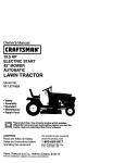
ERAFTSMAN®
46" FRO·NT MOUNTED
2 STAGE SNOW THROWER
ATTACHMENT
h CAUTION: Additional rear wheel weights are required to stabilize
f t the tractor when the snow thrower is mounted to it.
Caution:
Read and follow all
Safety .,Rules and
Instructions Before
Operating This
Equipment
Chains are required for traction while removing snow. Rear drawbar mounted
weights are also recommended to increase traction in severe conditions.
•
•
•
•
•
Assembly'
Operation
Customer Responsibility
Service and Adjustment
Repair Parts
Sears, Roebuck and C~'" Hoffman Estates, IL 60179 U.S.A.
•
•
•
•
A
SAFETY RULES
Safe Operation Practices for the Snow Thrower Attachment
Know the controls and how to stop quickly.
OWNER'S MANUAL
.
READ THE
Do not allow children to operate vehicle. Do not allow adults to
operate it without proper instruction.
Do not carry passengers.
distance away.
Keep children and pets a safe
Always wear substantial footwear. Do not wear loose fitting
clothes that could get caught in moving parts.
•
Keep your eyes and mind on your tractor, snow thrower and the
area being cleaned. Don't let other interests distract you.
•
Do not attempt to operate your tractor or snow thrower when not
in the drivers seat.
•
•
Always get on or off your tractor from the operators left side.
•
•
•
•
•
•
Disengage all attachment clutches and shift into neutral before
attempting to start the engine.
Disengage power to attachments and stop the engine before
leaving the operator's position.
Disengage all power to snow thrower, stop the engine, remove
key from ignition switch before cleaning, making an adjustment
or repairs.
Disengage power to attachments when transporting or not in
use.
Drive slowly when front or rear mounted attachment is in
transport position.
Take all possible precautions when leaving the vehicle
unattended, such as disengaging the attachment clutch lever or
switch, lowering the attachments, shift tractor into neutr~, setting
the parking brake, stopping the engine, and removing the key.
•
Do not stop or start suddenly when going uphill or downhill.
•
Reduce speed on slopes and make turns gradually to prevent
tipping or loss of control. Exercise extreme caution when
changing direction on slopes,
•
Do not shift gears while going up or down slopes. Choose a
•
•
•
•
•
•
•
Use care when pulling loads or using heavy equipment.
•
•
•
•
Use counterweights or wheel weights and tire chains when
suggested in this owner's manual.
•
•
•
•
•
Clear the work area of objects which might be picked up and
thrown.
gear low enough to negotiate the slope without stopping and
shifting gears.
•
Never shift gears until tractor comes to a stop.
•
Never place hands or feet near the snow auger, in the deflector
(discharge chute) or near any moving parts while tractor or
snow thrower is running. /JJways keep clear of discharge chute.
Umit loads to those you can safely control.
Do not tum sharply. Use care when backing.
Watch out for traffic when crossing or near roadways.
When using any attachments, never direct discharge of materiaJ
toward bystanders nor allow anyone near the vehicle while in
operation.
Handle fuel with care - it is highly flammable.
Use approved fuel containers.
Never remove the cap of the fuel tank or add fuel 10 a running or
hot engine, or fill the tank indoors. Wipe up spilled fuel.
Open doors if the engine is run in the garage; exhaust fumes are
dangerous. Do not run the engine indoors.
Keep the vehicle and attachments in good operating condition,
and keep safety devices in place. When using Three Point Hitch
remove attachments from hitch before making any repairs on
attachment or hitch.
•
Never store equipment'with fuel in the tank inside a building
where fumes may reach an open flame or spark. Allow the
engines 10 cool before storing in any enclosure.
•
To reduce fire hazard, keep the engine free of grass, leaves or
excessive grease.
•
The vehicles and attachments should be stopped and inspected
for damage after striking a foreign object, and the damage should
be repaired before restarting and operating the equipment.
•
Do not change the engine governor settings or overspeed the
engine.
•
When using the vehicle with a snow thrower, proceed as follows:
• Remove snow only in daylight or in good artificiaJ light
• Never make any adjustments while the engine is running if the
operator must dismount to do so.
• Shut the engine off when unclogging chute.
•
Additional rear wheel weights are required to stabilize the
tractor when the snow thrower is mounted to it.
LOOK FOR THIS SYMBOL TO POINT alIT IMPORTANT
SAFETY PRECAUTIONS. IT MEANS-ATTENTION!
BECOME ALERT! YOUR SAFETY lS It-.'VOLVED.
2
I.
Never run snow thrower into heavy material at high speeds.
Keep all nuts, bolts, and screws tight, all cotter pins and retainer
springs in place 10 be 'sure the equipment is in safe working
condition.
.
Do not drive too close to creeks, ditches and public highways.
(
Use only approved drawbar hitch points.
•
Stay alert for holes in the terrain and other hidden hazards.
Exercise special car6 when removing snow around fixed objects
in order to prevent the blades from striking them: Neller
deliberately run tractor or snow thrower into or over any foreign
objects.
A
(
CONGRATULATIONS on your purchase of a Sears Craftsman Snow Thrower. It has been designed, engineered and
manufactured to give you the best possible dependability
and performance.
Should you experience any problem you cannot easily
remedy, please contact your nearest Sears Service
Center/Department. We have competent, well-trained
te~hnicians and the proper tools to service or repair this
CUSTOMER RESPONSIBILITIES
•
•
•
Read and observe the safety rules.
Follow a regular schedule in maintaining, caring for
and using your Snow Thrower.
Follow the instructions under "Customer Responsibilities" and "Storage" sections of this Owner's
Manual.
Unit.
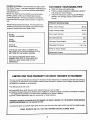
PRODUCT SPECIFICATIONS
Please read and retain this manual. The instructions will
enable you to assemble and maintain your Snow Thrower
properly. Always observe the "Safety Rules."
MODEL
NUMBER: 842.242560
SERIAL
NUMBER,
_
DATE OF
PURCHASE
_
Width of Snow Pickup
.46.0 in.
Auger Housing Height
23.5 in.
Snow Auger Diameter
,13.0 in.,
Discharge Opening
6.0 in.
Discharge Chute Rotation.
240
Adjustable Skid Shoes
oto 1.5 in.
Power by Tractor Engine
THE MODEL AND SERIAL NUMBERS WILL
BE FOUND ON A PLATE ATTACHED TO THE
LEFT SIDE OF THE AUGER HOUSING.
Replaceable Scraper
YOU SHOULD RECORD BOTH SERIAL
NUMBER AND DATE OF PURCHASE AND
KEEP IN A SAFE PLACE FOR FUTURE
REFERENCE.
LIMITED ONE YEAR WARRANTY ON SNOW THROWER AlTACHMENT
For one (1) year from the date of purchase, if this Snow Thrower Attachment is maintained, lubricated and tuned up
according to the instructions in the owner's manual, Sears will repair or replace, free of charge, any parts found to
be defective in material or workmanship.
This Warranty does not cover:
•
•
Expendable items which become worn during normal use, such as belts.
Repairs necessary because of operator abuse, negligence, improper storage or accident or the failure to maintain
the equipment according to the instructions contained in the Owner's Manual.
• Snow Thrower Attachment used for commercial or rental purposes.
WARRANTY SERVICE IS AVAILABLE BY RETURNING THE SNOW THROWER TO THE NEAREST SEARS SERVICE
CENTER/DEPARTMENT IN THE UNITED STATES.
This Warranty gives you specific legal rights, and you may also have other rights which may vary from state to state.
SEARS. ROEBUCK AND CO., 0/817 WA. HOFFMAN ESTATES, IWNOIS 60179
3
0
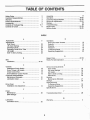
TABLE OF CONTENTS
(
Assembly.............................................................. 17
Operation
18-20
Customer Responsibilities
21-22
23-24
Service & Adjustments
Storage................................................................. 25
26
Troubleshooting.........
Repair Parts
27-33
Service Notes
34-35
Safety Rules.................
2
Customer Responsibilities.....................................
3
3
Warranty...............................................................
Product Specifications...........................................
3
Accessories...........................................................
5
Contents of Hardware Bag..................................... 6-7
8
Contents of Carton................................................
INDEX
A
Accessories...........................................................
Adjustments:
Skid Shoes.........................................................
Lift Assist Springs...............................................
Discharge Chute........
Discharge Chute Drive Tube..........
Lift Height..
Side To Side Leveling
o
5
Operation:
Know your Snow Thrower
Controls.............................................................
Stopping..........................................
Transport
To Remove Snow...........
Operating Suggestions
23
24
24
24
23
23
18
18
19
19
19
20
R
Repair Parts
Rules For Safe Operation
B
Belt:
Installation
27-33
2'
14-16
C
Controls:
Attachment Clutch Switch..................................
Snow Thrower Lift Handle..................................
Chute Control Rod.........................
Snow Deflector Control Handle..........................
Customer Responsibilities:
Maintenance Schedule
Lubrication Chart................................................
S
Service And Adustments:
Drive Chain.......
Lift Assist Springs.............
Lift Height.........
Side to Side Leveling........................................
Skid Shoes.......................................................
Service:
Maintenance Schedule
Storage................................................................
Snow Removal:
To Remove Snow.............................................
Operating Suggestions
Specifications......................................................
18
18
18
18
21
21
D
Drive Chain:
Installation And Adjustment................................
F
Finish:
Maintenance......................................................
(See Storage)
L
Lubrication:
Lubrication Chart................................................
14
24
24
23
23
23
21
25
19
20
3
T
25
Troubleshooting Chart ..
W
Warranty..............................................................
22
4
26
3
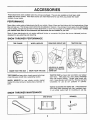
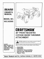
ACCESSORIES
These attachments were available when the unit was pruchased. They are also available at most Sears retail
outlets and service centers. Most Sears stores can order these items for you when you provide the model
number of your tractor.
PERFORMANCE
Sears offers a wide variety of attachments that fit your vehicle. Many of these are listed below with brief explanations of how
they can help you. This list was current at the time of publication; however, it may change in future years more attachments
may be added, changes may be made in these attachments, or some may no longer be available or fit your model. Contact
your nearest Sears store for the accessories and attachments that are available for your unit.
Most of these attachments do not require additional hItches or conversion kits (those that do are indicated) and are
designed for easy attaching and detaching.
SNOW THROWER PERFORMANCE
TIRE CHAINS
KNOW YOUR TIRE SIZE
DRAW BAR WEIGHT BAR
WHEEL WEIGHTS
TRACTOR CAB
HOLDS 55 LB. WHEEL
WEIGHT TO TRAGrOR
DRAW BAR
KNOW YOUR TIRE SIZE
TRACTOR CAB has heavy duty vinyl fabric over tubular
steel frame. ASS plastic top; clear plastic windshield
offers 360 degree visibility. Hinged metal doors with
catch. Keeps operator warm and dry. Remove vinyl and
windshields for use as sun protector in summer.
TIRE CHAINS are heavy duty; closely spaced extra-large
cross links give smooth ride, outstanding traction.
WHEEL WEIGHTS for rear wheels provide needed
traction for snow removal or dozing heavy materials. In
pairs.
Optional accessories for tractor cab: tinted /tempered
solid safety glass windshield with hand operated wiper;
12 volt amber caution light for mounting on cab top.
SNOW THROWER MAINTENANCE
V-BELTS
SKID SHOES
5
SCRAPER
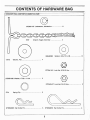
CONTENTS OF HARDWARE BAG
HARDWARE BAG CONTENTS SHOWN FULL SIZE
©
STD551137 Lockwasher, 3/8 Medium
5737
Chain & Toggle Assembly.......... .......... ..... 2
GM446363
17570
6
Washer, Flat............
Washer, 3/8 x 7/8 x .08
6
4
@
STD541431 Lock Nut, 5/16-18 Hex
STD551050 Washer, 17/32 x 1-1/16
5714
Spring Clip
o
~I
STD624005 Hair CoUer Pin.............
4
@
2
STD541437 Lock Nut, 3/8-16 Hex
3
6
5
STD624010 Hair Cotter Pin
6
4
/
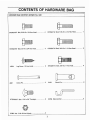
CONTENTS OF HARDWARE BAG
HARDWARE BAG CONTENTS SHOWN FULL SIZE
STD523107 Bolt, 5/16-18 x 3/4 Hex Head
4
STD523112 Bolt, 5/16-18 x 1-1/4 Hex Head
1
STD523707 Bolt, 3/8-16 x 3/4 Hex Head
3
STD523712 Bolt, 3/8-16 x 1-1/4 Hex Head
2
2
STD523710 Bolt, 3/8-16xl" Hex Head
4
14004
Lag Screw 1/2 Hex Head
0 _ - -01
4001
Clevis Pin
·· .. ··· .. · 2
STD533107 Bolt - 5/16 x 3/4' Carriage
3
21363 Nut - 5/16-18 Hex Nylock
3
3433
Clevis Pin.................................................. 2
22794 Stack Anchor
7
3
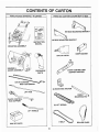
CONTENTS OF CARTON
------------------------------(
PARTS PACKED SEPARATELY IN CARTON
PARTS BOX CONTENTS SHOWN NOT TO SIZE
RH REAR MOUNTING BRACKET
LH REAR MOUNTING BRACKET
INSTRUCTION
MANUAL
MOUNTING ASSEMBLY
RAMP ANCHOR
BAG OF PARTS
<J
"
HEADER &
AUGER ASSEMBLY
(
<J
"
CHUTE CONTROL ROD
SUPPORT ANCHOR
DISCHARGE
CHUTE
...,
CHUTE CONTROL
ROD & EXTENSION
(2) MOUNTING ANCHOR
LIFT ROD
(2) LIFT SPRING
~;:--:-:\
I' /
(,.,'I
LIFT HANDLE
l
~
\'Ji
\"-"
ROLLER CHAIN
BOX OF PARTS
8
I
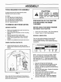
ASSEMBLY
TOOLS REQUIRED FOR ASSEMBLY
CAUTION
A socket wrench set will make assembly easier.
Standard wrench sizes are listed.
(1)
(1)
(1)
(2)
(2)
(2)
BEFORE STARTING TO ASSEMBLE
SNOW THROWER TO TRACTOR,
REMOVE SPARK PLUG WIRE(S) FROM
PLUG(S) AND KEY FROM TRACTOR
IGNITION.
Knife
3/8" Open End or Socket Wrench
7/16" Open End or Socket Wrench
1/2" Open End or Socket Wrench
9/16" Open End or Socket Wrench
3/4" Open End Wrench
PREPARATION OF THE TRACTOR
FOR MOUNTING THE SNOW
THROWER
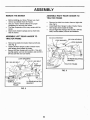
TO REMOVE UNIT FROM CARTON
BEFORE USING YOUR SNOW THROWER
WINTERIZE YOUR TRACTOR
UNPACK CARTON
•
•
•
•
•
Remove all accessible loose parts and parts box
from carton. (See Fig. 1)
Remove lag screw and plastic tie from mounting
channel.
Remove inner pack from inside carton.
Cut down all four corners of carton from top to
bottom and lay panels flat for clean mounting
surface.
Check for any additional loose parts and remove.
•
•
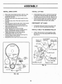
ENGINE LUBRICATION
Only use high quality detergent oil rated with API
service classification SG. Select the oil's SAE
viscosity grade according to your expected operating
temperature.
CHECK CARTON CONTENTS
•
Check and set tire pressure. (See Tractor Manual)
Change Tractor oil. (See Tractor Manual)
~
Check all loose parts, box, and bag contents
against carton contents and bag contents shown in
manual.
OF -20°
°e .29·
0°
·18°
32°··
O·
60·
16·
80·
2r
100·
38°
NOTE: Although multi-viscosity oil (5W30, 10W30.
etc.) improve starting in cold weath~r, these multiviscosity oils will result in increased oil consumption
when used above 32 F. Check your engine oil level
more frequently to avoid engine damage from running
low on oil.
•
•
•
•
•
FIG. 1
When right and left are mentioned in this manual, it
means when you are in the operating position (seated
behind the steering wheel)
•
9
Drain and refill gas tank with fresh gas.
NOTE: In cold climate areas the gasoline sold at
stations is winterized for cold weather starting
problems. (Do Not use gasoline purchased during
the Summer.)
Clean and gap spark plugs. (Replace if electrodes
are burned or damaged.)
Inspect, clean and or replace Air Cleaner.
Check Battery fluid level and add water to fill if
necessary. (See Tractor Manual)
Clean and tighten both Positive and Negative
terminals of the battery. (See Tractor Manual)
ASSEMBLY
-----------------------(
REMOVE THE MOWER
•
•
•
•
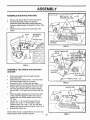
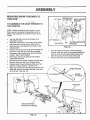
ASSEMBLE RIGHT REAR HANGER TO
TRACTOR FRAME
Before installing your Snow Thrower, you must
remove your Mower from the Tractor.
See your Tractor Owner's Manual for proper
procedures for removing the mower.
The Rear Suspension Arms may remain with the
tractor.
Store seven retainer springs and two front links
with the mower.
•
•
•
ASSEMBLE LEFT REAR HANGER TO
TRACTOR FRAME
•
•
•
Remove two bolts from tractor frame at right side.
(See Fig 3)
Install Right Rear Hanger to side of tractor frame
with hanger clevis toward the inside.
Secure Right Rear Hanger with two 3/8 x 3/4 hex
bolts, one flat washer, and two lock washers.
3/8 X 3/4 HEX BOLT
lOCK WASHER
_
Remove two bolts from tractor frame at left side.
(See Fig. 2)
Install Left Rear Hanger to side of tractor frame
with hanger clevis toward the inside.
Secure Left Rear Hanger with one 3/8 x 1 hex bolt,
one flat washer, and one lock washer, and one 3/8 x
3/4 hex bolt with one lock washer.
~LOCK WASHER
'0 0
LOCK WASHERS
RH REAR MOUNTING
BRACKET
3/8 X 1 HEX BOLT
..J FLAT
~
FLAT
WASHER\ '"
I
WASHER
I I \ \ \ \
FIG. 3
E
lH REAR MOUNTING
BRACKET
TRACTOR
FRAME
3/8 X 3/4 HEX BOLT
FIG. 2
10
(
ASSEMBLY
s
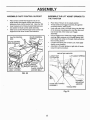
ASSEMBLE MOUNTING ANCHORS
•
•
•
"
BOLT 3/8 X 1 1/4
WASHER 3/8 LOCK
Remove 3/8" Nylock Nut from the tractor frame.
Assemble Mounting Anchor over bolt and
reassemble Nylock Nut While holding Mounting
Anchor at approximately 45 degrees to frame. (See
Fig 4)
Repeat the above steps on the right side of the
tractor
@.
'--~
MOUNTING
ANCHOR
"POINTE~
/NYLOCK NUT
CRANK ROD SUPPORT
ANCHOR
FIG. 5
FIG. 4
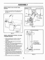
ASSEMBLE THE CRANK ROD SUPPORT
ANCHOR
•
•
•
•
•
•
•
Remove the plastic cap from height indicator
scale. (See Fig 7)
Disassemble and discard 5/16 x 1" bolt that holds
the height indicator scale to the tractor.
Remove two 3/8 x 1/2 bolts and the height
indicator pointer from the side of the tractor frame.
Position the Crank Rod Support Anchor over the
two holes and secure it with one 3/8 lock washer
and one 3/8 x 1 1/4" bolt in the front hole (See Fig
5)
Place the height indicator point over the rear hole
of the Crank Rod Support Anchor and secure it
parallel with one 3/8 lock washer and one 3/8 x I
1/4" bolt.
Place 5/16 x 1 1/4" hex bolt through 5/16 lock
washer, one 11/32 x 1 1/2 flat washer, height
indicator scale, one 11/32 x 1 1/2, four 1/8" thick
washers and secure to tractor lift shaft. (See Fig. 6)
Reassemble plastic cap.
NOTE; When mower is reassembled to the tractor, the
'
height indicator scale should be adjusted.
/
HEIGHT INDICATOR
FIG. 6
11
FIG. 7
ASSEMBLY
----------------------(
•
PREPARATION OF THE SNOW
THROWER FOR MOUNTING TO THE
TRACTOR
ASSEMBLE DISCHARGE CHUTE TO SNOW
THROWER HEADER
•
•
•
•
•
•
•
•
3/8 NUT & LOCKWASHER
ASSEMBLY
Loosen 3/8" Nut and Lockwasher Assembly that holds
Chute Control Cable Assembly to the Auger Housing
and move cable down away from Anchor Mounts.
(See Fig. 8 & 9)
Insert 5/16 x 3/4" Carriage Bolt through one of the
holes in the Stack of the Auger Housing with the
head of the bolt to the inside of the stack. (See Fig. 8)
place one Stack Anchor onto the bolt.
Install 5/16-18 Nylock Hex Nut finger tight onto bolt.
Install, finger tight, two other Carriage bolts, Stack
Anchors and Nylock Nuts to the remaining two holes
of the Stack.
Lubricate the outside of the Auger Housing Stack
and the inside of the Discharge Chute with WD-40
or equal.
Install Discharge Chute onto the Stack of the Auger
Housing with the discharge opening facing forward.
Place hook of Stack. Anchors over the lip of the
Discharge Chute, push Stack Anchors up, Pull out to
seat square of carriage bolt in hole and tighten Nylock
Nut at all three Stack Anchors.
I
5/16 X 3/4"
CARRIAGE BOLT
While keeping tight pressure to the left on the Chute
Control Cable Assembly, remove cable tie from the
cable, slide the Chute Control Cable Assembly to
the left until cable is taut and retighten 3/8" Nut and
Lockwasher Assembly to secure Chute Control
Cable Assembly
1/4 HEX BOLT
1/4 FLAT WASHER
CHUTE CONTROL CABLE
(LOOPS)
DISCHARGE
CHUTE
,\
~nOM
OF
DISCHARGE CHUTE
FIG. 9
AUGER HOUSING
STACK
CHUTE GUARD
~
DISCHARGE
CHUTE
\
5/16-18 NYLOCK
\ HEX NUT
~
FIG. 8
•
Move the Chute Control Cable up from the Stack of
the Auger Housing onto the bottom of the Discharge
Chute. (See Fig. 9)
NOTE: Make sure top strand coming off Chute Control
Cable Assembly goes around front of Discharge Chute.
•
Place both loops of the Chute Control Cable over
the 1/4" Hex Bolt and the 1/4" Flat Washer on the
right hand side of the Discharge Chute.
FIG. 10
12
ASSEMBLY
REMOVE DRIVE CHAIN COVER FROM
HEADER
•
HEADER/CHANNEL
SUPPORT
Remove six cap screws from drive chain cover and
set aside screws and cover for reinstalling later.
(See Fig 11)
2X4
2X4
MOUNTING
CHANNEL
FIG. 12
/
DRIVE CHAIN
COVER
MOUNTING CHANNEL
o
FIG. 11
INSTALL MOUNTING CHANNEL TO SNOW
THROWER HEADER
•
•
•
•
•
•
•
•
Before proceeding with mounting, cut three 2x4
boards approximately 25" long to be used in
mounting.
Place one 2x4 under each end of snow thrower
header. (See Fig 12)
Place front of the mounting channel onto top of
mounting lip of snow thrower header then slide third
2x4 under rear of mounting channel.
Secure finger tight only, front of mounting channel
to mounting lip of snow thrower header with three
3/8 x 1" hex bolts and three 3/8 hex lock nuts.
Remove the three 2x4s from under the unit.
Pivot the Snow Thrower forward onto front of the
Auger Housing. (See Fig. 13)
Insert four 5/16 x 3/4 hex bolts, two at each side, up
through four holes at sides of mounting channel,
through header/channel supports and secure hand
tight with four flat washers and four 5/16 hex lock
nuts.
Secure all bolts which were hand tightened.
DRIVE SHAFT
5/16 HEX BOLTS
FLAT WASHERS
5/16 HEX LOCKNUTS
~~t/i"itI-DRIVE SPROCKET
FIG. 13
13
ASSEMBLY
(
INSTALL DRIVE CHAIN
INSTALL LIFT ROD
•
•
•
•
•
•
•
•
•
•
•
Place chain around large sprocket. (See Fig. 13A)
Compress idler tension spring and install chain
around idler sprocket.
Pull both loose ends of the chain toward the drive
sprocket.
Assemble loose ends of the chain toward the drive
sprocket.
Pull chain tight to allow the last roller of each end to
fit into adjacent notches of the drive sprocket.
Insert connecting link up through the holes in the
chain and install link strap.
Install retaining clip to secure link strap.
NOTE: Retaining clip must be installed with the
closed end toward the direction of rotation.
Tighten idler tension nut until idler spring is
compress.ed to 5/8 to 3/4 of an inch.
Pivot the Snow Thrower backward and lower the
mounting channel to the ground.
Reinstall the Drive Chain Cover and six screws.
•
Install adjustment anchor of Lift Rod through nole
in right end of front lift assembly and secure with
flat washer and small hair cotter pin. (See Fig. 14)
Install Lift Rod through hole in strap of lift bar and
secure with flat washer and small hair cotter pin
with rod toward inside and pin to the outside.
DISCONNECT LIFT LINKS
•
Temporarily disconnect control rod anchor of lift
link rod from front lift assembly at both sides
INSTALL V-BELT TO GEARBOX PULLEY,
•
Install V-belt into groove around gearbox pulley
and place to left of the spring loaded idler pulley.· .
(See Fig 14)
.
FRONT LIFT
ASSEMBLY
ADJUSTMENT
ANCHOR
SMALL HAIR
~~==::'h-JClj}oTT~
-,-;
FLAT WASHER
IDLER
TENSION
NUT
GEARBOX PULLEY
)
1-----l.-1"",...,,;:i~\tt:1';',t.~;;:::::_C_DRIVE:+--+-~---SPROCKET
IDLER
TENSION
,5/S·
SPRING
TOI
3/4'
LINK STRAP I :
.
FIG. 14
~
~CONNECTING
LINK
FIG.13A
14
(
ASSEMBLY
MOUNTING SNOW THR. OWER TO
TRACTO~:'
"~',
LIFT BAR
MEDIUM HAIR
COITER PIN
REAR HANGER
' " ~ BRA\CKET
'I
o@
NOTE: Before installing the snow thrower to your
tractor you will be required to assemble a ramp to
assist in the installation of the Snow Thrower to the
TraCtor
•
•
•
,
•
•
•
•
•
•
(
Use one 2x4 which you have all ready cut to
assemble the ramp.
Place the ramp anchor in the center of the board
and secure with two lag screws. (See Fig 15)
Move the Mover Lift Handle of the tractor to the
raised position.
Position The ramp on top of the Snow Thrower lift
bar as far to the right of the lift bar as possible. ,
Disengage tractor transmission with Free Wheel
Control. (See Tractor Manual)
Roll tractor fOlWard until right front tire makes
contact with the ramp.
Roll right front tire by hand, forward over the ramp.
Remove ramp from the Snow Thrower lift bar.
Position Snow Thrower Mounting Channel in line
with the mounting brackets. (See Fig. 15)
Raise rear of Snow Thrower Mounting Channel and
place 2x4 under the mounting channel in the area
of the lift bar. (See Fig. 16)
RH REAR MOUNTING
BRACKET
CLEVIS PIN
FIG. 16
•
•
Use Lift Handle to lift Snow Thrower Mounting
Channel, align the holes of rear hanger plates with
holes in clevis of rear hanger plates, and secure
with clevis pins and medium hair cotter pins.
Remove 2X4 from under mounting channel.
BOARD
2 X4X25"
TRACTOR
--
SNOW THROWER
MOUNTING CHANNEL
FIG. 15
15
/
=
ASSEMBLY
(
INSTALL PIN THROUGH FRONT LIFT
ASSEMBLY
INSTALL IDLER LOCATING ROD
•
•
•
•
•
•
Move Snow Thrower Lift Handle forward to lowered
position.
Turn front wheel of tractor to left as far as they will
turn. (See Fig. 17)
Align tube of front lift assembly with holes in tractor
Attachment plates and insert pin through plate
holes and tube.
Secure pin with large hair cotter pin at each end.
Straighten tractor wheels to front.
•
Slide idler locating rod to the left and insert end of
idler locating rod into bottom hole in tractor frame.
(See Fig. 18)
Secure idler locating n;>d to tractor with small hair
cotter pin
IDLER LOCATING ROD
RECONNECT LIFT LINKS
•
Install control rod anchor of lift link rod into each
side of front lift assembly and secure with small
hair cotter pins. (See Fig. 17)
FRONT LIFT
ASSEMBLY
V-BELT
SMALL HAIR
ENGINE PULLEY COTTER PIN
FIG. 18
ASSEMBLE LIFT HANDLE TO THE SNOW
THROWER
•
Slide Lift Handle over the end of the lift Bar with
the offset toward the operators position of the
tractor. (See Fig. 1 9 ) ' >
•
OPERATOR'S POSITION
FIG. 17
INSTALL V-BELT TO TRACTOR
•
Roll V-belt around engine pulley from right side to
left side. (See Fig. 18)
16
FIG. 19
ASSEMBLY
ASSEMBLE CHUTE CONTROL SUPPORT
•
•
•
ASSEMBLE THE LIFT ASSIST SPRINGS TO
THE TRACTOR
Place Chute Control Rod Support over pin on
chute control rod support anchor and secure by
tightening chute control anchor bolt. (See Fig. 20)
Insert hooked end of Chute Control Rod Extension
into eyebolt of chute control cable assembly.
Slide Chute Control Rod through Chute control rod
support and into chute control rod extension.
•
•
•
•
CHUTE CONTROL
ROD
CHUTE CONTROL
ROD EXTENSION
•
•
Place Snow Thrower in the raised position.
Thread Chain and Toggle Assembly through the
mounting anchor. (See Fig 21)
Hook one end of the Lift Assist Spring into the hol~ ,
of the channel mounting anchor and the other end
into the last link of the Chain and Toggle
Assembly.
Pull on toggle end of Chain and Toggle Assembly,
exerting slight pressure on Lift Assist Spring, then
insert large hair cotter pin through chain just above
the mounting anchor.
If Chain and Spring are not taunt, you must apply
slightly more pressure.
Assemble Lift Assist Spring on right side of tractor
using the same procedure.
MOUNTING ANCHOR
LARGE HAIR
COTTER PIN
LIFT ASSIST SPRING
~
CHUTE CONTROL
SUPPORT
ANCHOR
,
,
CHUTE CONTROL
ANCHOR BOLT
FIG. 20
~
CHANNEL
MOUNTING
ANCHOR
\
CHAIN AND TOGGLE
ASSEMBLY
TOGGLE END
Fig. 21
17
OPERATION
(
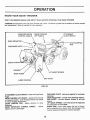
KNOW YOUR SNOW THROWER
READ THIS OWNER'S MANUAL AND SAFETY RULES BEFORE OPERATING YOUR SNOW THROWER
COMPARE the illustrations with your Snow Thrower and Tractor. Familiarize yourself with the location of various controls
and adjustments. Save the manual for future reference.
SNOW DEFLECTOR
CONTROL HANDLE
SNOW THROWER
LIFT HANDLE
\
SNOW DEFLECTOR
DISCHARGE CHUTE -
ATIACHMENT
CLUTCH SWITCH
CHUTE CONTROL
ROD
~\
(
SNOW AUGER
AUGER HOUSING
FIG. 22
DISCHARGE CHUTE - holds snow together for controlled
discharge.
SNOW DEflECTOR - controls snow discharge distance.
SKID SHOES - controls distance Scraper Is set from
ground.
UFT ASSIST SPRINGS - control the amount of weight that
is forced down on the Scraper.
SHEAR PINS· one in each auger and one in throwe'
fan for protection from heavy shock load damage. Pins
must be replaced if sheared to continue operation
AlTACHMENT ClUTCH SWITCH - starts and stops Snow
Auger.
SNOW THROWER UFT HANDLE - selects Snow removal
or transport position. (This will replace Mower Lift Handle
for Snow Thrower Attachments)
CHUTE CONTROL ROD - selects direction of snow
discharge.
SNOW DEFlECTOR CONTROL HANDLE - selects
distance snow is discharged.
18
OPERATION
Th~ operation of ~ny Snow Thrower can result in foreign objects thrown into the eyes
which can result In severe eye damage. Always wear safety glasses or eye shields
before stanlng and dUring operation of Snow Thrower. We recommend wide vision
safety mask for over the spectacles or standard safety glasses.
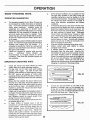
HOW TO USE YOUR SNOW THROWER
SNOW DISCHARGE DISTANCE CONTROL
(See Fig. 22)
•
STOPPING
•
•
Move Attachment Clutch Switch to "DISENGAGED"
position.
TO REMOVE SNOW
HOW TO CLEAR A PLUGGED
DISCHARGE CHUTE
•
•
If Snow Thrower becomes plugged with snow or jammed
due to hitting an obstruction, proceed as follows:
•
•
A CAUTION A
•
•
•
•
•
•
•
•
The distance snow will be discharged can be
adjusted by moving the Snow Deflector.
To increase distance snow Is discharged, pull down
on Snow Deflector Control Handle and lock In
position.
•
•
Disengage Attachment Clutch Switch
Shut off Tractor.
Set Parking Brake.
Remove spark p1ug(s) wire(s).
Remove Uft Handle and use it to push snow back
down into Auger Housing.
Reassemble Uft Handle.
Replace spark plug(s) wire(s).
Resume snow removal.
Turn Discharge Chute Control Rod to desired
direction of discharge.
Move Snow Deflector to desired discharge
distance.
Stan Tractor Engine and move ThrotUe Control to
full speed.
Move Attachment Clutch Switch to "ENGAGED"
position.
Push forward on Uft Handle to lower Snow
Thrower to ground level.
Select lowest Tractor ground speed at Tractor Full
Throttle and engage Tractor Ground Drive.
LIFT ASSIST SPRINGS
•
The Uft Assist Springs help In carrying the weight
of the Snow Thrower. For extra scraping ability In
packed or hardened snow, decrease Spring
Tension.
SKID SHOES
•
TRANSPORT
•
•
Always transport with the Snow Thrower in the raised
position and the Attachment Clutch Switch
disengaged.
Pull back on Snow Thrower Uft Handle until it locks
In the up position.
TO CONTROL SNOW DISCHARGE
•
The Chute Control Rod controls the direction of the
discharge. Turn rod to the right to direct snow to the
right side of the Tractor and turn it to the left for the
opposite effect.
19
The Skid Shoe mounted on each side of the Auger
Housing adjusts the distance scraping Is raised
above the surface. When removing snow from an
uneven surface or a gravel driveway, It Is advisable
raising scraper as high above the surface as
possible to prevent possible damage to the snow
Auger and to help prevent stones from being
thrown with snow. On blacktop or concrete, keep
the scraper as close to the scraping surface as
possible.
OPERATION
•
SNOW THROWING HINTS
OPERATING SUGGESTION
•
•
•
The operating capacity of your Snow Thrower can
be increased by careful observance of operating
rules. Your Snow Thrower is capable of handling
heavy snow conditions.
However, giving the
equipment the opportunity to function within
reasonable requirements will assure you of longer
equipment life, less possibility of damage to the
unit and require less power to operate. Make
certain that you are totally familiar with all aspects
of both the Tractor and your Snow Thrower prior
to its usage.
The Snow Auger speed is directly related to engine
speed. For maximum snow removal and discharge
maintain high engine RPM (full throttle). It is
advisable to operate the Tractor at a slow ground
speed for safe and efficient snow removal. (Usually
first gear at full throttle)
Chains are required for traction while removing
snow.
Additional Wheel Weights are
recommended to increase traction in severe
conditions. Rear Draw Bar Mounted Weights are
also available.
•
•
•
•
IMPORTANT OPERATING HINTS
•
•
•
•
•
•
•
Check the Tractor and Snow Thrower to make
certain both are in good operating condition.
Fill gas tank out of doors and avoid spilling
gasoline over engine. Do NOT fill tank with
gasoline while smoking or while engine is running.
Do NOT remove any guards or covers while
operating Tractor and Snow Thrower or make any
adjustments while dismounted from the operating
position.
Before the first snowfall, the area in which snow
removal is to take place should be cleared of all
stones, sticks and the like which might be picked
up by the Snow Auger. All obstacles should be
marked to protect the Tractor and Snow Auger
from possible collision.
A light coat of wax applied to the inside surface of
the Auger Housing will prevent snow and ice from
sticking to it. The inside of the Discharge Chute
and Deflector should be waxed several times
during the snow removal season.
For best results, snow should be removed as soon
as possible after it falls.
In deep, drifted, or banked snow, it will be
necessary to use full throttle and a slow forward
ground speed. Drive the Snow Auger into the
snow, depress Tractor Clutch-Brake Pedal and
allow Snow Auger to clear snow. Repeat this
method until a path is cleared. On second pass
overlap the first enough to allow the Snow Auger
. to handle the snow without repeated stopping and
starting Tractor ground speed.
Snow removal conditions vary so greatly from the (
first light fluffy snowfall to wet heavy snow that
operating instructions must be flexible to fit the
snow removal encounter. The operator must adapt
the Tractor and Snow Thrower to the depth of
snow, wind direction, temperature and surface
conditions.
In extremely deep snow, raise Snow Thrower from
ground and drive ahead into snow to remove top
layers first, keeping Tractor out of snow bank. Do
NOT enter Tractor into snow bank where snow has
not been removed to ground level. Disengage
Tractor Clutch and allow Snow Thrower to clear
snow. Reverse Tractor and lower Snow Thr'Jwer to
the ground. Drive Tractor and repeat process to
remove balance of snow. Working with repeated
passes into and out of drifts will eventually move
even the deepest of snow piles.
Whenever possible discharge snow down wind.
Always overlap each pass slightly to assure
i
complete snow removal.
A definite pattern of operating is required: to
thoroughly clean the snow area. (See Fig. 23)
This pattern will avoid a second removal of snow
and avoid throwing snow in unwanted places.
Where it is possible to throw snow to the right and
left, as on a long driveway. it is advantageous to
start in the middle. Work from one end to the (
opposite end throwing snow to both sides without
changing the direction of Discharge Chute.
FIG. 23
•
If snow can only be thrown to one side of the
driveway or sidewalk, start on the opposite side.
At the end of each succeeding pass rotate the
Discharge Chute 180 to maintain direction of snow
throw into the same area. (See Fig. 24)
NO Sl<JW PllED ON l.£I'T SIDE
START ON LEFT SlOE
E."-- ~Are B1lOW 1110 OEGSES <~
20
FIG. 24
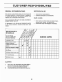
CUSTOMER RESPONSIBILITIES
GENERAL RECOMMENDATIONS
BEFORE EACH USE
The warranty on this Vehicle does not cover items that
have been subjected to operator abuse or negligence.
To receive full value from the warranty, operator must
maintain unit as instructed in this manual.
•
•
ONCE A YEAR
Some adjustments will need to be made periodically to
properly maintain your unit.
•
All adjustments in the Service and Adjustments section
of this manual should be checked at least once each
season.
MAINTENANCE
SCHEDULE
FILL IN DATES
AS YOU COMPLETE
REGULAR SERVICE
<f
J
~
~
~
0
.:t
~ ~w:
~ ~~
0 OJ'
.:t ~~ ~
q9
IV~ ~
:2'
cr
~~ rf: <F8" ~
~ ~ ~ ~
Qj
ii:
'?
q; q;
~
~~
Lubrication Chart
Check V-belt condition,
replace if required
Check and Adjust Chain
tension
./
~
~
Check and Adjust LIft Height
~
Skid Shoes
V'
Discharge Chute Drive Tube
~
Lift Assist Springs
V"
Discharge Chute
•
V'"
CLEANING
•
•
•
Once a year you should chck and replace if worn,
V-belts, Chain, Scraper and Skid Shoes.
Check Snow Auger and straighten if necessary.
~
!iJ
~
Check unit for loose fasteners.
Lubricate Discharge Chute with WD-40.
Wash off any salt deposit which may have dried on
the Snow Thrower with standard garden hose.
Paint any exposed metal with spray bomb.
Protect painted surfaces with automotive type wax..
21
SERVICE DATES
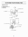
CUSTOMER RESPONSIBILITIES
(
LUBRICATION CHART
CD
®
@
@
General purpose grease
White grease Lubri-plate #GR 132
90 Wt gear lube
WD-40 or equal
®
CD
DISCHARGE CHUTE
BEARINGS
~'+.-I!----+--- CD
®
BLOWER FAN
DRIVE CHAIN
@ ALL PIVOT POINTS
®
@ PULLEY GEARBOX
22
FRONT LIFT PIN
(
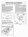
SERVICE AND ADJUSTMENTS
LIFT HEIGHT ADJUSTMENT
•
•
•
•
Lower snow thrower to ground.
Loosen outside nut at end of lift rod. (See Fig 25)
Adjust inside nut of lift rod until channel box hits
front lift assembly when snow thrower is raised.
Retighten outside nut against inside nut to lock nuts
together.
SKID SHOE
2 X 4 BLOCK
SIDE TO SIDE LEVELING ADJUSTMENT
•
•
•
•
•
•
•
Raise snow thrower to up position.
Measure from ground to bottom edge of header at
each side.
If adjustment is required remove control rod anchor
of lift link from one side of front lift assembly.
Adjust control rod anchor and reinstall to front lift
assembly.
Lower header to ground and raise again.
Measure from ground to bottom edge of header to
see if adjustment is l.:orrect..
If unit is still not level repeat procedure.
FIG. 26
TO ADJUST SKID SHOES FOR USE ON
GRAVEL DRIVEWAYS OR
UNEVEN
SURFACES
•
•
•
•
FRONT LIFT
ASSEMBLY
INSIDE NUT
OUTSIDE NUT
•
•
•
Place Snow Thrower in raised posi~ion.
Place 2 X 4 blocks under both ends of the scraper.
Lower Snow Thrower Scraper onto 2 X 4 blocks.
Loosen six Nuts on the outside of the Auger Housing
which secure the Skid Shoes.
Allow Skid Shoes to drop to the ground.
Retighten six Nuts securing Skid Shoes.
Lower Snow Thrower to ground level.
NOTE: Make sure both Skid Shoes are adjusted to keep
Scraper level even with scraping surface.
TO ADJUST SKID SHOES FOR USE ON
CONCRETE OR EVEN SURFACES
•
•
•
•
CHANNEL BOX
Place Snow Thrower in raised position.
Loosen six Nuts on the outside of Auger Housing
which secure the Skid Shoes.
Lower Snow Thrower to ground level.
Retighten six Nuts to secure Skid Shoes.
SCRAPER AND SKID SHOES
FIG. 25
Both the Scraper and Skid Shoes are subject to wear
and are designed for easy replacement. Replace before
wear is excessive to prevent damage to the Auger
Housing or Snow Auger.
SKID SHOE ADJUSTMENT
The Skid Shoe mounted on each side of the Header
Housing adjusts the distance scraping is raised above the
surface. When removing snow from an uneven surface or
a gravel driveway, it is advisable raising scraper as high
above the surface as possible to prevent possible damage
to the Snow Auger and to help prevent stones from being
thrown with snow. On blacktop or concrete, keep the
scraper as close to the scraping surface as possible.
NOTE: New Scraper may be purchased when original
equipment is worn. This repair Scraper is bolted to the
Header Housing replacing the worn Scraper.
23
SERVICE AND ADJUSTMENTS
----------------------------(
DISCHARGE
ADJUSTMENT
CHUTE
DRIVE
LIFT ASSIST SPRINGS
TUBE
•
• If Discharge Chute will not hold its position and tends
to rotate, adjust Lock Nut on end of Discharge Chute
Tube Eye Bolt. Tighten Lock Nut 1/8 turn and check
rotation of Discharge Chute Drive Tube by turning
Chute Control Rod. A small amount of resistance
should be encountered. Do not over tighten. Tighten
until Discharge Chute holds its position. (See Fig. 28)
• The Snow Thrower has a discharge radius of 240 and
is controlled by the Chute Control Rod. The
Discharge Chute Stop Bolt will prohibit rotation
beyond this point. (See Fig. 27)
•
•
The Lift Springs (Fig. 29), assist in carrying the weight
of the Snow Thrower. For extra scraping ability in
packed or hardened snow, reduce tension of Lift
Assist Springs.
With Snow Thrower in the raised position pull up on
Chain & Toggle and remove Hair Cotter Pin. Allow
several links of chain to pass down through hole in
the Mounting Anchor and replace Hair Cotter Pin just
above Mounting Anchor. To decrease scraping action
when Snow Thrower is used on rough surfaces•
increase tension on Lift Assist Spring by removing
Hair Cotter Pin and Pulling several links up through
hole in Mounting Anchor and replacing Hair Cotter
Pin.
Chain & Toggles should be adjusted evenly.
LIFT ASSIST
SPRINGS
(
FIG. 27
CHUTE CONTROL CABLE HOOK-UP
• Chute Control Cable is wound around Discharge
Chute Drive Tube 2-1/2 turns each way; both ends of
equal length. This will allow equal angle of Discharge
Chute in both directions.
FIG. 29
DISCHARGE CHUTE
TUBE, EYE BOLT
FIG. 28
24
STORAGE
REMOVING THE SNOW THROWER
NOTE: The following items can be left assembled to
the Tractor and will not interfere with the Rotary Mower,
but may need to be removed for other attachments.
Left Rear Hanger
Right Rear Hanger
Control Rod Support Anchor
(2) Mounting Anchors
This Snow Thrower has been designed so that some parts
which are difficult to assemble and remove may be left on
the Tractor with mower operation
•
•
•
•
•
•
•
•
•
•
•
•
•
•
•
•
•
•
•
•
Place Tractor on level ground.
Shut off Tractor and remove ignition key.
Remove spark plug wire(s) from spark plug(s).
Put attachment Clutch Switch in the "disengaged"
position.
Set parking brake.
Place Mower Lift Handle in "raised" position.
Pull backward on Chute Control Rod removing it
from the Chute Control Rod Support.
Unhook Chute Control Rod Extension from
Discharge Tube Eyebolt..
Loosen Chute Control Rod Support Bolt And lift
Chute Control Support off Chute Control Rod
Support B r a c k e t . ·
Place Snow Thrower in "raised" position
Pull Large Hair Cotter Pins from Chain & Toggle
Assemblies.
Disconnect Chain & Toggle Assemblies from Lift
Assist Springs and remove.
Place Snow Thrower in the "lowered" position.
Disconnect Idler Locator Rod from tractor frame.
Remove V-Belt from around Tractor Engine Pulley.
Remove Front Mounting Pin from Front Lift
Assembly.
Remove Clevis Pin from both rear Hangers.
Allow Snow Thrower to drop to ground.
Install ramp to Lift Bar and roll right front tire by
hand rearward over Lift Bar.
Collect all loose hardware anf place in a plastic bag
which should be tied to your Snow Thrower for
storage.
STORING SNOW THROWER
NOTE: At the end of the snow season the following steps
are recommended:
•
•
•
•
•
•
BEFORE USING YOUR ROTARY
DEWINTERIZE
YOUR
MOWER
TRACTOR
•
Change Tractor oil to summer grada.
Only use high quality detergent oil rated with API service
classification SG. Select the oil's SAE viscosity grade
according to your expected operating temperature.
OF -20·
°C -29·
CAUTION
A
Remove Snow Thrower Assembly from Tractor.
Wash off any salt deposit which may have dried on
the Snow Thrower and Auger Housing.
Paint exposed metal.
Lubricate the Snow Thrower following the Lubrication
Chart
The Snow Auger Chain must be oiled thoroughly to
stop rust from forming.
Store Snow ThroWer In a dry place.
BEFORE REMOVING THE LOCATING PIN
FROM THE LEFT FRONT HANGER,
REMOVE ANY TOOLS AND KEEP HANDS
AND FEET OUT FROM UNDER SNOW
THROWER. AFTER THE LOCATING PIN
IS REMOVED FROM LEFT FRONT
HANGER THE SNOW THROWER WILl..
DROP TO THE GROUND AND MAY
CAUSE INJURY IF ANYTHING OR
ANYONE IS UNDER IT.
NOTE: Although multi-viscosity oils (5W30, 10W30, etc.)
Improve starting in cold weather, these multi-viscosity oils
will result in increased oil consumption when used above
32 F. Check your engine oil l.eveJ more frequently to
avoid possible engine damage from funning low on 011.
•
25
Wash off any salt deposit which may have dried on
the Tractor.
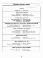
TROUBLESHOOTING
(
PROBLEM:
Probable Cause -
Possible Remedy
AUGER HOUSING VIBRATION
Failed Bearing No lubrication on Drive Chain Damaged Discharge Fan -
Bring to Sears Service Center
Oil Drive Chain
Balance or Replace Discharge Fan
CLOGGED DISCHARGE CHUTE
Tractor ground speed too fast Tractor Throttle too low Snow too deep -
Use lower Tractor Gear
Use full Tractor Throttle
Raise Snow Thrower
DISCHARGE CHUTE IS DIFFICULT TO ROTATE OR WILL NOT HOLD POSITION
Discharge Chute Drive Tube Nut too loose Chute Control Cable too loose Discharge Chute and Stack Ring are dry -
Tighten Tube Lock Nut
Adjust Chute Control Cable Assembly
Grease all the way around
SNOW THROWER DOES NOT OPERATE
V-Belt too loose
V-Belt not in Pulley Groove
Drive Chain rolled or failed
Shear Pin Broken
-
(
Replace V-Beft
Check V-Belt and place back in Groove
Reposition and adjust or Replace Chain
Replace Shear Pin
BURNED RUBBER SMELL
V-Belt loose or worn V-Belt not in Pulley Grooves Object jammed in Snow Auger -
Replace V-Belt
Chuck Pulley And place back into groove
Shut Off Tractor, Free Auger
SNOW THROWER WILL NOT LIFT
Adjusting Nuts Loosened Object jammed between Mounting Frame and Tractor
Adjust And Tighten Nuts
Clear Obstruction
SNOW THROWER KILLS TRACTOR ENGINE
'--
Object jammed in Snow Auger Very hard or heavy snow Very wet snow -
Clear Snow Auger
Slow Tractor ground speed
Increase Tractor Throttle
26
-J (
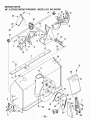
REPAIR PARTS
46" 2 STAGE SNOW THROWER - MODEL NO. 842.242560
Ref.
No. Part No.
Description
1.
23201
Gearbox Case R. H.
2.
23202
Gearbox Case L. H..............................................
3.
23213
Input Shaft...........................................................
4.
23212
Key, Hi Pro #606..................................................
5.
23217
Quad Ring............................................................
6.
23216
Flange Bearing....................................................
7.
23214
Washer, .752 x 1.24,x .093..................................
8.
23215
Thrust Bearing
9.
23210
Worm Gear
10.
23211
Sleeve Bearing....................................................
11.
23206
Output Shaft
12.
23207
Key, #91 Woodruff...............................................
13.
23204
Oil Seal.................................................................
14.
23203
Gearbox Bearing.................................................
15.
23205
Washer, 1" x 1.64 x .093......................................
16.
23208
Worm Wheel Gear...............................................
17.
23209
Gear Case Gasket...............................................
18.
23218
Pipe Plug 1/4-18 NPTF
19. GM181608* Bolt, 5116-24 x 1" Hex Hd....................................
20. GM181614* Bolt, 5/16-24 x 1-1/2 Hex Hd
21. GM9415152* Lock Nut, 5/16-24 Hex Flange
*Standard Hardware - Purchased Locally
27
Qty.
1
1
1
1
1
1
2
1
1
1
1
1
2
2
2
1
1
1
6
2
8
REPAIR PARTS
46" 2 STAGE SNOW THROWER - MODEL NO. 842.242560
'-~3
21~ 11}0
i;lA·~
,-
12
13
9
~~12
11
I
I
I
I
I
I
8
10
I
,-
I
I
,;-
;-
I
3')
I
I
I
,;-
/
/
;-
I
/
;-
;
I
~3
1
c>
,- ;
I
/'"
I
I
I
I
I
(:)
I
I
I
I
I
I
I
;-
,-
I
I
I
I
I
I
I
I
I
,,-
/
/
/
/0
l ....
5
43
-28-
/
36
REPAIR PARTS
46" 2 STAGE SNOW THROWER - MODEL NO. 842.242560
Ref.
No.
Part No.
1.
2.
3.
4.
5.
6.
7.
8.
9.
10.
11.
12.
13.
14.
15.
16.
17.
18.
19.
20.
21.
22.
23.
24.
25.
26.
23498
22680
STD533107*
GM271184*
22668
STD533110*
GM446363*
23177
23176
4001
5714
5074
GM446188*
GM454668*
23167
23172
5473
STD551131*
STD541031*
23200
23113
STD523707*
STD541437*
23114
STD541431*
GM941152*
28.
29.
30.
31.
32.
33.
34.
35.
36.
37.
38.
39.
40.
41.
42.
43.
STD580103*
GM142671*
STD522520*
STD541425*
- )316§' _
23117
23118
21363
23119
15683
STD523710*
STD523107*
23555
23569
22794
8456
ill:.. - J311~,
Description
Header Housing
Scraper Blade
Bolt, 5/16-18 Carriage
Nut & Lockwasher Assy 5/16-18
Skid Shoe
Bolt, 5/16-18 x 1" Carriage
Washer, 3/8 x 7/8 x .083 Flat..
Auger Assembly Left Hand
Auger Assembly Right Hand
Shear Pin
Spring Clip
Grease Fitting
Washer, 17/32 x 5/8 x .049
Roll Pin 3/16 x 1-1/4
Thrower Fan
Bearing
Flangette
Lockwasher 5/16 Medium
Nut, 5/16-18 Hex
Worm Drive Gearbox Assembly
Bronze Bearing Assembly
Bolt, 3/8-16 x 3/4 Hex Hd
Lock Nut, 3/8-16 Hex
Gearbox Support Bracket
Lock Nut, 5/16-18 Hex
Lock Nut, 5/16-24 Hex Flange
~
Sprocket & Hub Assembly
2:~~.D..L.:
Key, 3/16 Square x 7/8
Setscrew, 5/16-18 x 1/2 Sq. Hd. Cup pt
Bolt, 1/4-20 x 2 Hex Hd
Lock Nut, 1/4-20 Hex
Drive Chain with Connecting Link "
Header/Channel Support Left Hand
Header/Channel Support Right Hand
Nylock Nut, 5/16-18
Chain Drive Cover
Self Tapping Screw 1/4-14
Bolt, 3/8-16 x 1" Hex Hd
Bolt, 5/16-18 x 3/4 Hex Hd
Danger Decal
Caution Decal
Stack anchor
Chain Repair Connecting Link
aty.
.
.
.
.
.
.
.
..
.
.
..
..
..
.
.
.
.
.
.
.
.
.
..
.
..
.
'
..
.
.
.
.
.
.
.
.
.
.
.
.
..
..
..
1
1
21
15
2
6
22
1
1
3
3
3
3
1
1
1
2
3
3
1
2
8
11
1
6
2
1 3. (g ~~,
1
1
1
1
1..1
1
7
1
6
3
4
2
1
3
1
*Standard Hardware - Purchased Locally
29
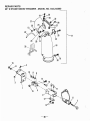
REPAIR PARTS
46" 2 STAGE SNOW THROWER - MODEL NO. 842.242560
(
17
(
1
4
I ........
I
I
~
12~
13~
-30-
REPAIR PARTS
46" 2 STAGE SNOW THROWER - MODEL NO. 842.242560
Ref.
No. Part No.
Description
I.
23120
Stack Drive Support Bracket.............................
2. STD533107* Bolt, 5/16-18 x 3/4 Carriage................................
3. GM273802* Lock Nut, S/16-18 Hex Flange
4.
9030
Stack Drive Shroud
S.
9032
Bracket & Tube Assembly.................................
6.
8346
Cable, Tube & Sleeve Assembly.......................
7.
3966
Eye Bolt
8. GM120388* Washer, 7/16 x 1" X .083.....................................
9.
4772
Spring Washer
10. STD641437* Lock Nut, 3/8-16 Hex...........................................
11.
8236
Level Wind "un Bolt
12.
8299
Friction Strap
13. STD54142S* Lock Nut, 1/4-20 Hex
14. STD533707* Bolt, 3/8-16 x 3/4 Carriage..................................
1S. GM271190* NutiLockwasher Assy 3/8-16 Hex......................
16. STD533710* Bolt, 3/8-16 X 1" Carriage...................................
17.
23121
Denector & Elbow Assy, (Complete)
18.
23123
Elbow.................................................................
19. STDS22S0S*· Bolt, 1/4-20 x 1/2 Hex Hd
20.
3903
Washer, 9/32 x 1" x 1/16.....................................
21.
19449
Denector & Decal Assembly..............................
22.
19417
Seal Trim..............................................................
23. STD522507* Bolt, 1/4-20 X 3/4 Hex Hd
24.
4506
Washer, 13/32 x 1-1/2 x .051................................
25.
19691
Denector Lock Spring
26. STD522517* Bolt, 1/4-20 x 1-3/4 Hex Hd
27.
19482
Denector Lock Strap...........................................
28.
19483
Rubber Handle Grip............................................
29.
19484
Rubber Grommet
30.
19718
Washer, Flat
31. STD523106* Bolt, 5/16-18 x 5/8 Hex Hd
32. STD541431* Lock Nut, 51'16-18 Hex........................................
33.
22509
Chute Guard
Qty.
1
3
3
1
1
1
1
2
1
1
1
1
S
1
2
1
1
1
2
S
1
1
2
2
1
1
1
1
1
1
1
1
1
*Standard Hardware - Purchased Locally
31
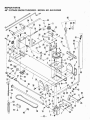
REPAIR PARTS
46" 2 STAGE SNOW THROWER - MODEL NO. 842.242560
(
66
67
o
68 69
--i~
61-1
60
I
62
64
"-
36
7
~1
55
63
73~
~
74~I
48
50
3
-32-
/
REPAIR PARTS
46" 2 STAGE SNOW THROWER - MODEL NO. 842.242560
Ref,
No.
Part No.
Description
1.
23125
Mounting Channel............................................
2.
23129
Gearbox Mounting Bracket
3.
23179
Gearbox
4. STD523712* Bolt, 3/8-16 x 1-1/4 Hex Hd
5. STD54143T" Nut, 3f8-16 Hex Lock
6.
23130
Pulley..................................................................
7.
19968
Key, #6 Woodruff................................................
8. STD623710* Bolt, 3/8-24 x 1" Hex Hd......................................
9. STD55113T" Lockwasher, 3/8 Medium
10. GM142671* Screw, 516-18 x 1/2 Sq. Hd. Cup Pt.
11. STD52310T" Bolt, 5/16-18 x 3/4 Hex Hd
12.
23132
Belt Guide Bracket..............................................
13. STD523110*BoIt, 5/16-18 x 1" Hex Hd....................................
14. STD541431*Nut, 5/16-18 Hex Lock.........................................
15.
23133
Drive Coupling
23134
Drive Shaft
16.
17.
23172
Bearing.................................................................
18. STD522517* Bolt, 1/4-20 x 1-3/4 Hex Hd
19. STD541525*Nut, 1/4-20 Hex Lock...........................................
20
23137
Bearing Housing. Complete
21.
23506
Idler Mounting BrackeL.....................................
22.
3166
Idler Sprocket......................................................
23140
Hub Insert
23.
24. STD523715* Bolt, 3/8-16 x 1-1/2...............................................
25. GM446363* Washer, 3/8 x 7/8 x .083......................................
26. STD533712* Bolt, 3/8-16 x 1-1/4 Carriage
27. GM120388* Washer, 7/16 x 1" x .083.....................................
28.
21362
Nylock Nut, 3/8-16 Hex Lock
29.
23141
Idler Mounting
30.
23143
Idler Arm..............................................................
31.
15015
Idler Pulley..........................................................
32. STD523717* Bolt, 3/8-16 x 1-1/4 Hex Hd
33.
20186
Idler Spring..........................................................
34. STD551050*Washer, 17/32 x 1-1/16 x .095.............................
35. GM120123* Cotter Pin, 1/8 x 1-1/4.........................................
36. STD523707*BoIt, 3/8-16 x 3/4 Hex Hd
23146· Idler Locating Rod
37.
38.
23141
Rear Hanger Bracket
39.
23148
Lift Bar
40. STD511810*RolI Pin.................................................................
41. STD551075*Washer, 13/16 x 1-1/2 x .134...............................
42.
6179
Spacer
43.
23151
Lift Bar Mounting Strap
44.
23156
Front Lift Assembly............................................
45.
23159
Lift Link Rod........................................................
46.
9492
Control Rod Anchor
41. STD624005* Hair Cotter Pin.....................................................
48.
13180
Mounting Frame Anchor
49. STD523110* Bolt, 3/8-16 x 1" Hex Hd......................................
50.
11483
V-Belt....................................................................
L. H. Rear Mounting Bracket
51.
23152
R. H. Rear Mounting Bracket
52.
23153
53.
3433
Clevis Pin.............................................................
54.
23158
Pi.n
55. STD624010* Hair Cotter Pin.....................................................
56.
23160
Lift Rod
57.
19649
Adjustment Anchor
58. STD541150* Nut, 112-20 Hex
59.
11154
Lift Handle Assembly.........................................
60.
21631
Lift Handle
61.
3339
Handle Grip
62.
1213
Raise & Lower Decal..........................................
Lift Spring............................................................
63.
4198
54.
5131
Chain & Toggle Assembly.................................
65.
18158
Control Rod Support Anchor
66.
18759
Control Rod Support (complete)......................
Qty.
1
1
1
4
17
1
1
1
7
2
2
1
2
4
1
1
1
2
2
1
1
1
1
1
6
2
1
2
1
1
1
1
1
3
4
13
1
2
1
1
2
1
2
1
2
2
9
4
3
1
1
1
2
1
4
1
1
2
1
1
1
1
2
2
1
1
*Standard Hardware - Purchased Locally
33
Ref.
No.
Part No.
61.
68.
69.
10.
11.
12.
73.
14.
15.
16.
11.
78.
19
80.
18162
16124
11112
21191
15431
8206
21111
14004
S·211
14405
23503
23501
4112
23163
Description
Qty.
Control Rod Support
Control Rod Guide Bushing...............................
Chute Control Decal............................................
Thumb Screw.......................................................
Control Rod
Control Rod Extension
Ramp Anchor Bracket
Lag Screw, Hex Head
Key, #9 Woodruff
Idler Spring
Idler Arm...............................................................
Idler Spring Rod
Washer, Belleville................................................
Instruction Manual..............................................
1
1
1
1
1
1
1
2
2
1
1
1
1
1
\
SERVICE NOTES.
-------------------------(
,/ ?
-l.... ..•. ~'"
-""
/
~
c"'---
r
.e~._ .:.-\:~ ~~,~--=
.) (._ ..:..,.,,_
r,
,
f
......
/(
t "-',_ t.:.. ......... ~:-.. .. -'-
..-2....
Jq
'"
,-: ...
(".
II
(
34
SERVICE NOTES
35
\
(
S~AIR/S
OWNER'S
MANUAL
MODEL NO.
,842.242560
I:RAFTSMAN@
46" FRONT MOUNTED
2 STAGE SNOW THROWER
ATTACHMENT
The Model Number will be found on a plate on the left side, attached to
the Auger Housing. Always mention the Model Number when requesting
service on repair parts for your Snow Thrower.
All parts listed herein may be ordered from any SEARS, ROEBUCK AND
CO., service center and most retail stores.
WHEN ORDERING REPAIR PARTS, ALWAYS GIVE THE FOLLOWING
INFORMATION:
HOW TO ORDER
REPAIR PARTS.
•
PRODUCT - 46" 2 STAGE SNOW THROWER
•
MODEL NUMBER - 842.242560
•
PART NUMBER
•
PART DESCRIPTION
Your Sears merchandise has added valuE;! when you consider Sears has
service units nationwide staffed with Sears trained
technicians... professional technicians specifically trained to insure that we
meet our pledge to you, we service what we sell.
t
...
Sears, Roebuck and Co., Hoffman Estates, II 60179 U.S.A.
/
-------------------------------------/
23163 (8.15.96)
PRINTED IN U.S.A.