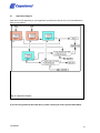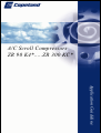
1
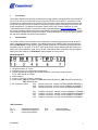
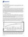
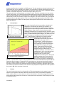
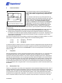
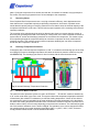
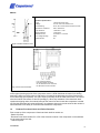
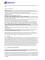
A/C Scroll Compressors ZR 90 K4*.....ZR 300 KC* Application Guideline Index Page Page 1 Introduction 3 22 Shell Temperature 11 2 Nomenclature 3 23 Brief Power Interruptions 11 3 Qualified Refrigerants 4 24 Electrical Installation 11 4 Compressor Handling 4 25 Electrical Connections 12 5 Lubrication and Oil Removal 4 26 Cable Connectors 12 6 Accumulators 5 27 Compressor Functional Check 13 7 Screens 5 28 Excessive Liquid Floodback Tests 13 8 Crankcase Heaters 6 29 High Potential Testing 14 9 Pumpdown 6 30 Compressor Mounting 15 10 Minimum Run Time 6 31 Installation and Service Brazing Procedure 15 11 Reversing Valves 7 32 Installation System Charging Procedure 16 12 Discharge Temperature Protection 7 33 Suction and Discharge Fittings 16 13 Electronic Motor Protection 7 34 Shut-off Valves and Adaptors 17 14 Protector Functional Test 8 35 Unbrazing System Components 18 15 Mufflers 9 36 Compressor Replacement 18 16 Suction Line Noise and Vibration 9 37 Start-up of a New or Replacement Compressor 18 17 Low Ambient Cut-Out 10 38 Rotation Direction 18 18 Pressure Safety Controls 10 39 R 407 C Characteristics 18 19 Shut-off Sound 11 40 Application Envelopes 20 20 Starting 11 41 Application Diagram 21 21 11 Deep Vacuum Operation C6.2.2/0701/E 2 1 Introduction This bulletin describes the operating characteristics, design features, and application requirements for 7.5 to 25 HP A/C Scroll Compressors in the range from ZR 90 K3 to ZR 300 KC. This family of scroll compressors is characterized by the pilot duty motor protection system that uses internal sensors and an external electronic module to protect the compressor against motor overheating and excessive discharge temperature. For additional information, please refer to the “Product Catalogue“ or to the “Copeland Selection Software” accessible from the Copeland website at www.ecopeland.com. There are several operating characteristics and design features described below that are different from those of the smaller Copeland Scroll compressor models. These guidelines are not meant to replace the system expertise available from system manufacturers. 2 Nomenclature The model numbers of the Copeland Scroll compressors include the approximate nominal 60 Hz capacity at standard operating conditions. An example would be the ZR90K3-TWD, which has approximately 90,000 Btu/hr cooling capacity at the ARI high temperature air conditioning rating point when th operated on 60 Hz. The letter “K” in the 5 place of the model number indicates that the number preceding it is to be multiplied by 1000, “M” by 10,000. Note that the same compressor will have approximately 5/6 of this capacity or 75000 Btu/hr when operated on 50 Hz current. Model Designation 1 - compressor family: Z = Scroll 2 - application range: R = high/medium temperature 3 - nominal capacity [BTU/h] @ 60 Hz and ARI conditions (*see below) using multipliers "K" for 1000 and "M" for 10 000 4 - model variation 5 - oil type: E=POE oil, no value = mineral oil 6 - motor version: TWC (230V/3/60 Hz), TWD (400V/460V/3/50/60 Hz), TWE (500V/575V/3/50/60 Hz) TW7 (380V/3/60 Hz) 7 - bill of material number: 522: Brazing connection, 120/240 V module (ZR90K3*/ZR300KC*) 568: Brazing connection, 24 V AC module (ZR90K3* to ZR19M3*) 524: Brazing connection, 24 V AC module (ZR250KC*/ZR300KC*) 551: 523: 561: 525: Rotalock connection, 120/240 V module (ZR90K3* to ZR19M3*) Rotalock connection, 120/240 V module (ZR250KC*/ZR300KC*) Rotalock connection, 24 V AC module (ZR90K3* to ZR19M3*) Rotalock connection, 24 V AC module (ZR250KC*/ZR300KC*) *ARI-Conditions: 7,2 °C 54,4 °C 11 K C6.2.2/0701/E evaporating temperature condensing temperature suction gas superheat 8,3 K 35 °C liquid subcooling ambient temperature 3 3 Qualified Refrigerants R407C has been qualified as a replacement for R22 for the compressor models ZR 90 K3E ... ZR300 KCE. R134a is qualified for the models ZR 90 K3E…ZR 19 M3E. The application envelopes of each refrigerant are shown in Section 40. 4 Compressor Handling It is recommended that the plugs in the compressor line connections be left in place until the compressor is set into the unit. This reduces the chance of contaminants and moisture getting into the compressor especially if the compressor is charged with the more hygroscopic POE oil. If the compressor has two lifting tabs, both must be used for lifting. The discharge connection plug should be removed first before pulling the suction connection plug to allow the dry air pressure inside the compressor to escape. Pulling the plugs in this sequence prevents oil mist from coating the suction tube making brazing difficult. The copper-coated steel suction tube should be cleaned before brazing (see Fig. 13). No object (e.g. a swaging tool) should be inserted deeper than 50 mm into the suction tube or it might damage the suction screen. 5 Lubrication and Oil Removal The compressor is supplied with an initial oil charge. The standard oil charge for use with refrigerants R407C and R134a is a polyolester (POE) lubricant Copeland 3MA (32 cSt). In the field the oil level could be topped up with ICI Emkarate RL 32 CF or Mobil EAL Arctic 22 CC, if 3MA is not available. In R22 applications Suniso 3GS is used. Suniso 3GS is compatible with Texaco WF 32 and Fuchs KM. These oils may be used if an addition is required in the field. When a compressor is exchanged in the field it is possible that a major portion of the oil from the replaced compressor may still be in the system. While this may not affect the reliability of the replacement compressor, the extra oil will add to rotor drag and increase power usage. To remove this excess oil an access valve has been added to the lower shell of the compressor. The compressor should be run for 1 1 10 minutes, shut down and the access valve opened until oil is somewhere between /4 to /3 of the sight glass. This operation should be repeated at least twice to make sure the proper oil level has been achieved. Fig. 1: Absorption of moisture in ester oil in comparison to mineral oil in [ppm] by weight at 25°C and 50% relative humidity. h = hours. One disadvantage of POE is that it is far more hygroscopic than mineral oil (Fig.1). Only brief exposure to ambient air is needed for POE to absorb sufficient moisture to make it unacceptable for use in a refrigeration system. Since POE holds moisture more readily than mineral oil it is more difficult to remove it through the use of vacuum. Compressors supplied by Copeland contain oil with a low moisture content, and this may rise during the system assembling process. Therefore it is recommended that a C6.2.2/0701/E 4 properly sized filter-drier is installed in all POE systems. This will maintain the moisture level in the oil to less than 50 ppm. If oil is charged into a system it is recommended to charge systems with POE containing no more than 50 ppm moisture content. If the moisture content of the oil in a refrigeration system reaches unacceptable high levels, corrosion and copper plating may occur. The system should be evacuated down to 0.3 mbar or lower. If there is uncertainty, as to the moisture content in the system, an oil sample should be taken and tested for moisture. Sight glass/moisture indicators currently available can be used with the HFC refrigerants and lubricants; however, the moisture indicator will just show the moisture contents of the refrigerant. The actual moisture level of POE would be higher than the sight glass specifies. This is a result of the high hygroscopicity of the POE oil. Oil samples would have to be taken from the system and analyzed to determine the actual moisture content of the lubricant. 6 Accumulators Due to the Copeland Scroll’s inherent ability to handle liquid refrigerant in flooded start and defrost cycle operation, an accumulator is not be required for durability in most systems, especially those systems designed with thermostatic expansion valves. However, large volumes of liquid refrigerant which repeatedly flood back to the compressor during normal off cycles or excessive liquid refrigerant floodback during defrost or varying loads, no matter what the system charge is, can dilute the oil. As a result, bearings are inadequately lubricated and wear may Fig. 2: Suction Accumulator occur. To test for these conditions see the section entitled Excessive Liquid Floodback Tests at Section 28. If an accumulator must be used, an oil return 2 orifice size in the range 2 mm is recommended. A large-area protective screen no finer than 30 x 30 mesh (0.6 2 mm openings) is required to protect this small orifice from plugging with system debris. Tests have shown that a small screen with a fine mesh can easily become plugged causing oil starvation to the compressor bearings. Accumulators are a standard item in air to air heat pumps and are used even when a thermostatic expansion valve is used to meter refrigerant in the heating mode. During low ambient conditions the oil returning from Fig. 3: Bottom Shell Temperature the outdoor coil will be very viscous and difficult to return through the accumulator if the expansion valve is working properly by maintaining superheat. To prevent slow oil return it may be possible to remove the accumulator from systems that use expansion valves in heating. To determine if the accumulator can be removed a defrost test must be done at an outdoor ambient of around 0 °C in a high humidity environment to ensure that excessive liquid does not flood back to the compressor during reversing valve operation, especially when coming out of defrost. Excessive flood back occurs when the sump temperature drops below the safe operation line shown in Fig. 3 for more than 10 seconds. 7 Screens 2 The use of screens finer than 30 x 30 mesh (0,6 mm openings) anywhere in the system is not recommended. Field experience has shown that finer mesh screens used to protect thermal expansion valves, capillary tubes, or accumulators can become temporarily or permanently plugged with normal system debris and block the flow of either oil or refrigerant to the compressor. Such blockage can result in compressor failure. C6.2.2/0701/E 5 8 Crankcase Heaters The crankcase heater must be mounted below the oil removal valve located on the bottom shell. The crankcase heater must remain energized during compressor off cycles. The initial start in the field is a very critical period for any compressor because all load bearing surfaces are new and require a short break-in period to carry high loads under adverse conditions. The crankcase heater must be turned on a minimum of 12 hours prior to starting the compressor. This will prevent oil dilution and bearing Fig. 4: Crankcase Heater Location stress on initial start up. If it is not feasible to turn on the crankcase heater 12 hours in advance of starting the compressor, then use one of the techniques listed below to prevent possible flooded-start damage to the compressor: 1) Direct a 500 watt heat lamp or other safe heat source (do not use torch) at the lower shell of the compressor for approximately 30 minutes to boil off any liquid refrigerant prior to starting; or 2) Bump start the compressor by manually energizing the compressor contactor for about one second. Wait five seconds and again manually energize compressor for one second. Repeat this cycle several times until the liquid in the shell has been boiled off and the compressor can be safely started and run continuously. Due to the Compliant Scroll’s inherent ability to handle liquid refrigerant in flooded conditions, no crankcase heater is required when the system charge does not exceed following values: · · · 7,7 kg 11,3 kg 13,6 kg for for for ZR 90 K3* ... ZR 19 M3* ZR 250 KC* ZR 300 KC* A crankcase heater is needed to drive out excessive amounts of refrigerant that have migrated into the shell during standstill periods and no accumulator is piped to provide free liquid drainage during the off cycle as shown in Fig. 2. Please also see Section 28. For correct mounting location of such a heater please see Fig. 4. 9 Pumpdown Recycling pumpdown for control of refrigerant migration may be used instead of, or in conjunction with, a crankcase heater when the compressor is located so that cold air blowing over the compressor makes the crankcase heater ineffective. The Scroll compressor discharge check valve is designed for low leak back and will allow the use of recycling pump down without the addition of an external check valve. The low pressure control cut-in and cut-out settings have to be reviewed since a relatively large volume of gas will re-expand from the high side of the compressor into the low side on shut down. A one time pump down at the end of a run cycle is not recommended since refrigerant can still migrate into the compressor after a long shut down. If a one time pump down is used a crankcase heater must be installed. 10 Minimum Run Time There is no set answer to how often scroll compressors can be started and stopped in an hour, since it is highly dependent on system configuration. There is no minimum off time, because the scrolls start unloaded, even if the system has unbalanced pressures. The most critical consideration is the minimum run time required to return oil to the compressor after startup. This is easily determined since these compressors are equipped with a sight glass. The minimum on time becomes the time required for oil lost on compressor startup to return to the compressor sump and restore a normal level in the sight C6.2.2/0701/E 6 glass. Cycling the compressor for a shorter time than this, for instance to maintain very tight temperature control can result in progressive loss of oil and damage to the compressor. 11 Reversing Valves Since Copeland Scroll compressors have a very high volumetric efficiency, their displacements are lower than those of comparable capacity reciprocating compressors. As a result, Copeland recommends that the capacity rating on reversing valves be no more than 2 times the nominal capacity of the compressor with which it will be used. This will ensure proper operation of the reversing valve under all operating conditions. The reversing valve solenoid should be wired so that the valve does not reverse when the system is shut off by the operating thermostat in the heating or cooling mode. If the valve is allowed to reverse at system shut-off, suction and discharge pressures are reversed to the compressor. This results in pressures equalizing through the compressor which can cause the compressor to slowly rotate until the pressures equalize. This condition does not affect compressor durability but can cause unexpected sound after the compressor is turned off. 12 Discharge Temperature Protection A thermistor with a nominal response temperature of 140 °C is located in the discharge port of the fixed scroll (Fig. 5). Excessive discharge temperature will cause the electronic protector module to trip (see also Section 13). The discharge gas sensor is wired in series with the motor thermistor chain. Fig. 5: Internal Discharge Temperature Protection 13 Electronic Motor Protection The electronic motor protection system as used in all ZR 90 K3* ... ZR 300 KC* models is identified by a “W” as the center letter in the motor code. This system utilizes the temperature dependent resistance of thermistors (also called PTC-resistances) to read the winding temperature. A chain of four thermistors connected in series is embedded in the motor windings so that the temperature of the thermistors can follow the winding temperature with little inertia. An electronic module is required to process the resistance values and trip a control relay depending on the thermistor resistance. The characteristic gradient of a thermistor resistance curve is shown in Fig. 6. The resistance curve can be designed for different operating points, the nominal response temperature (NAT), e.g. 80°C, 100°C, 140°C, and must comply with the tolerances laid out in the standard DIN 44081. C6.2.2/0701/E 7 Module Protector Specifications : Type: Voltage: Control Rating: Normal PTC resistance: Trip resistance: Reset resistance: Module time out: Low Voltage Sensing: Phase Monitor: Kriwan INT 69 SC/ Carel 24 V AC; 230 V AC,120/240 V AC 60 VA, 25 A Inrush 300/375 VA 25/15 A Inrush 250 to 1000 Ohms >4500 Ohm +/- 20% <2750 Ohms 30 minutes +/- 5 minutes None No Fig. 6: Thermistor Resistance Curve Fig. 7: Motor Protection Module Fig. 8: Carel Module L1/T1 neutral connection L2/T2 line voltage connection S1, S2 thermistor chain connection M1, M2 control circuit connection For protection in case of blocked rotor one thermistor for each phase is embedded in the winding heads on the upper (suction gas) side of the compressor motor. A fourth thermistor is located in a winding head at the lower end of the motor. A fifth sensor is located in the discharge port of the fixed scroll to control discharge gas superheat. The entire chain is internally led to the fusite from where it is connected to the module connections S1 and S2 (see Fig. 7). When any resistance of the thermistor chain reaches the tripping value, the module interrupts the control line and causes the compressor to switch off. After the thermistor has cooled sufficiently, its resistance drops to the reset value but the module itself resets after a time delay of 30 minutes and restarts the compressor. 14 Protector Functional Check and Failure Detection Prior to start-up of the compressor a functional check shall be carried out: - Switch off power! - Disconnect one terminal either S1 or S2 of the electronic module. If the compressor is now switched on, the motor should not start. - Switch off power. C6.2.2/0701/E 8 - Reconnect the disconnected thermistor line. If the compressor is now switched on the motor must start. Protector Fault Diagnosis: If the motor does not start-up during the functional check, this indicates a disturbance in operation: - Switch off power. - Check the connection of the thermistor leads in the terminal box and at the protection module for possible loose connections and check the connection cable for possible breakage. - The resistance of the thermistor chain shall be measured in a cold condition, i.e. after the motor has sufficiently cooled down. Caution: Use maximum measuring voltage of 3 V! In doing so, the thermistor leads at terminals S1 and S2 of the module shall be disconnected and measured between the leads. Resistance must be between 150 and 1250 ohms. If the thermistor chain has a higher resistance (2750 ohms or greater) the motor temperature is still too high and it has to be allowed to cool. If the resistor is 0 ohms, the compressor has to be exchanged due to shorted sensor circuit. ∞ ohms indicates an open sensor circuit and the compressor has to be replaced. If no defect is located in the thermistor chain or there is no loose contact or conductor breakage, the module shall be checked. Then the control connections at M1 and M2 have to be removed (Caution! Switch off voltage supply first!) and check the switching conditions by an ohmmeter or signal buzzer: - short-cut the already disconnected thermistor contactors S1 and S2 and switch on the voltage supply; the relay must switch; connection established between contactors M1 and M2 -remove the jumper between S1 and S2, the relay must switch off; no connection between contactors M1 and M2 - shortcut the contactors S1 and S2 again, the relay remains switched off; no connection between contactors M1 and M2 - switch off the voltage supply for approximately 4 sec and switch it on again, the relay must switch on now; connection between contactors M1 and M2 If one of the above conditions is not met, the module is defective and has to be exchanged. Note: The power should be switched off between the tests, in order to avoid short circuits and accidental touching of contacts. The function of the module should be tested each time the fuse in the control circuit breaks the power supply. This makes sure that the contacts did not stick. 15 Mufflers Flow through Copeland Scroll Compressors is semi-continuous with relatively low pulsation. External mufflers, which used to be applied to piston compressors, may not be required for Copeland Scroll. Because of variability between systems, however, individual system tests should be performed to verify acceptability of sound performance. When no testing is performed, mufflers are recommended in heat pumps. A hollow shell muffler will work quite well. The muffler should be located a minimum of 15 cm to a maximum of 45 cm from the compressor for most effective operation. The further the muffler is placed from the compressor within these ranges, the more effective it may be. If adequate attenuation is not achieved, use a muffler with a larger cross-sectional area to inlet-area ratio. The ratio should be a minimum of 20:1 with a 30:1 ratio recommended. The muffler should be from four to 10-15 cm long. 16 Suction Line Noise and Vibration Copeland Scroll compressors inherently have low sound and vibration characteristics. However, the sound and vibration characteristics differ in some respects from those of reciprocating compressors. In rare instances, these could result in unexpected sound complaints. One vibration characteristic of the scroll compressor may result in a low level “beat” frequency that may be detected as noise coming along the suction line into the building under some conditions. Elimination of the “beat” can be achieved by attenuating the contributing frequency. The most important frequency to avoid is the power supply line frequency for three phase compressors. The scroll compressor makes C6.2.2/0701/E 9 Fig. 8: Suction Tube Design both a rocking and torsional motion, and enough flexibility must be provided in the suction line to prevent vibration transmission into any lines attached to the unit. In a split system the most important goal is to ensure minimal vibration in all directions at the service valve to avoid transmitting vibrations to the structure to which the lines are fastened. A second difference of the Copeland Scroll is that under some conditions the normal rotational starting motion of the compressor can transmit an “impact” noise along the suction line. This may be particularly pronounced in three phase models due to their inherently higher starting torque. This phenomenon, like the one described previously, also results from the lack of internal suspension, and can be easily avoided by using standard suction line isolation techniques. The sound phenomena described above are not usually associated with heat pump systems because of the isolation and attenuation provided by the reversing valve and tubing bends. 17 Low Ambient Cut-Out Low ambient cutouts are not required to limit heat pump operation. However, the discharge temperature must be limited to 135°C or below otherwise the motor protection may trip. 18 Pressure Safety Controls High Pressure Control: Because these compressors do not have an internal pressure relief valve, a high pressure control with a maximum cut out setting of 28,8 bar must be used in the system. The high pressure control should have a manual reset feature for the highest level of system protection. Low Pressure Control: A low-pressure control is highly recommended for loss of charge protection. A cutout setting no lower than 2 bar for air conditioning and 0.5 bar for heat pumps is recommended. Even though these compressors have an internal discharge temperature sensor, loss of system charge etc. will result in overheating and recycling of the motor protector. Prolonged operation in this manner could result in oil pump out and eventual bearing failure. Operation near 0,5 bar (-32°C saturated suction temperature) is clearly outside the approved operating envelope of the compressor shown in Fig. 16. However, heat pumps in some geographical areas have to operate in this range because of the low ambient temperatures. This is acceptable as long as the condensing temperature is not above 32°C and the resulting discharge temperature is below 135°C. Some liquid floodback to the compressor under these conditions can help keep the discharge temperature under control. Certain conditions may cause even the 0.5 bar low-pressure control to cause nuisance trips. These could be temporary suction blockage during reversing valve operation; or lack of liquid pressure available to the metering device upon startup in heating. For this reason the lowpressure control can be moved to the liquid line where it won’t be subjected to momentary low suction pressures that can cause nuisance trips. An alternative is to keep the low-pressure control in the suction line and provide a 60-second (maximum) low-pressure time delay that ignores a signal from the low-pressure control and allows the compressor to continue operating. The low-pressure cutout, if installed in the suction line to the compressor, can provide additional protection against a TXV failed in the closed position, outdoor fan failure in heating, a closed liquid line or suction line service valve, or a blocked liquid line screen, filter, orifice, or TXV. All of these may starve the compressor for refrigerant and may result in compressor failure. The low-pressure cut out should have a manual reset feature for the highest level of system protection. C6.2.2/0701/E 10 19 Shut-off Sound Since Copeland Scroll compressors are also excellent gas expanders, they may run backward for a brief period at shutoff as the internal pressures equalize. A low mass, disc-type check valve in the discharge tube of the compressor prevents high pressure gas entering the compressor after shut down. Additionally there is a disk-type valve mounted on the fixed Scroll that effectively eliminates reverse rotation and allows pressure equalization within the compressor via a small bleed hole. Momentary reversal of direction of the scrolls has no effect on compressor durability and is entirely normal. Development testing should include a review of the shut-off sound for acceptability in a particular system. 20 Starting During the very brief start-up, a short metallic sound is audible, resulting from initial contacting of the spirals and is normal. Due to the design of the Compliant Scroll, the internal compression components always start unloaded even if system pressures are not balanced. In addition, since internal compressor pressures are always balanced at startup, low-voltage starting characteristics are excellent for Compliant Scroll compressors. 21 Deep Vacuum Operation Copeland Scroll compressors (as with any refrigerant compressor) should never be used to evacuate a refrigeration or air conditioning system. The scroll compressor can be used to pump down refrigerant in a unit as long as the pressures remain within the operating envelope shown in Fig. 16. Low suction pressures will result in overheating of the scrolls and permanent damage to the compressor drive bearing. An internal protection device unloads and stops the compressor pumping when the pressure ratio exceeds approximately 10. 22 Shell Temperature Certain types of system failures, such as condenser or evaporator fan blockage or loss of charge, may cause the top shell and discharge line to briefly but repeatedly reach temperatures above 177ºC as the compressor cycles on its internal protection devices. Care must be taken to ensure that wiring or other materials, which could be damaged by these temperatures, do not come in contact with these potentially hot areas. 23 Brief Power Interruptions No time delay is required on three phase models to prevent reverse rotation due to power interruptions. The torque of the motor is strong enough to assure proper rotation under all starting circumstances. 24 Electrical Installation Independently from the internal motor protection, fuses have to be installed before the compressor. Selection of fuses has to be carried out according to VDE 0635 or DIN 57635 or IEC 269-1 or EN 60-2691. Motor insulation material class is “H” for models ZR 90 K3 ... ZR 300 KC according to IEC 34-18-1, EN 0530, VDE 0530 or DIN 57530. The Fusite connections are marked as in Fig. 9. Recommended wiring diagram is shown in Fig. 10. C6.2.2/0701/E 11 25 Electrical Connections The orientation of the electrical connections on the Copeland Scroll compressors is shown in Fig. 9 and is also shown on the wiring diagram inside the terminal box cover. The screw terminals used on this compressor should be fastened with a torque of 2.5 to 2.6 Nm. Fig. 9: Motor Terminal Connections A1 B1 F1 F3 F4 K1 R2 S1 Y1 motor protection module room thermostat fuse high-pressure switch low-pressure switch contactor crankcase heater auxiliary switch liquid line solenoid valve Fig. 10: Control Circuit 26 Cable Connectors Model ZR 90 ZR 11 ZR 12 ZR 16 ZR 19 ZR 250 ZR 300 A Flag receptacle TW* B/C B/C B/C B/C B/C B/C B/C B Ring Tongue Module A A A A A A A C Spade Fig. 11: Cable Connectors C6.2.2/0701/E 12 The previous table lists recommended types of cable connectors to be used for the various electric terminals of the compressors and the motor protection module. “A” and “B” must fit 1/4" or 6.3 mm tab sizes. “C” is to be selected for #10 studs. Cable sizes are to be selected according to DIN ISO 0100, IEC 364 or national regulations. 27 Compressor Functional Check A functional compressor test with the suction service valve closed to check how low the compressor will pull suction pressure is not a good indication of how well a compressor is performing. Such a test will damage a scroll compressor. The following diagnostic procedure should be used to evaluate whether a Copeland Scroll compressor is working properly. 1. Proper voltage to the unit should be verified. 2. The normal checks of motor winding continuity and short to ground should be made to determine if an internal motor short or ground fault has developed. If the protector has opened, the compressor must be allowed to cool sufficiently to allow it to reset. 3. Proper indoor and outdoor blower/fan operation should be verified. 4. With service gauges connected to suction and discharge pressure fittings, turn on the compressor. If suction pressure falls below normal levels, the system is either low on charge or there is a flow blockage in the system. 5. If suction pressure does not drop and discharge pressure does not rise to normal levels, reverse any two of the compressor power leads and reapply power to make sure compressor was not wired to run in reverse direction. If pressures still do not move to normal values, either the reversing valve (if so equipped) or the compressor is faulty. Reconnect the compressor leads as originally configured and use normal diagnostic procedures to check operation of the reversing valve. 6. To test if the compressor is pumping properly, the compressor current draw must be compared to published compressor performance curves using the operating pressures and voltage of the system. If the average measured current deviates more than ±15% from published values, a faulty compressor may be indicated. A current imbalance exceeding 15% of the average on the three phases may indicate a voltage imbalance and should be investigated further. 7. Before replacing or returning a compressor: Be certain that the compressor is actually defective. As a minimum, recheck a compressor returned from the field in the shop or depot for winding resistance and ability to start before returning. More than one-third of compressors returned to Copeland for warranty analysis are determined to have nothing found wrong. They were misdiagnosed in the field as being defective. Replacing working compressors unnecessarily costs everyone. 28 Excessive Liquid Floodback Tests The following tests are for those system configurations and charge levels identified in Section 8 that need special testing to verify exemption from need of an accumulator. Fig. 3 applies only during floodback, not when the suction gas is superheated, and must be used to determine the effectiveness of an accumulator. The compressor sump temperature during any unit test where flood back occurs must remain within the "safe zone" shown in Fig. 3. To test for excessive continuous liquid refrigerant floodback, it is necessary to operate the system in a test room at conditions where steady state floodback may occur (low ambient heating operation). Thermocouples should be attached with glue or solder to the center of the bottom shell and to the suction and discharge lines approximately 15 cm from the shell. These thermocouples should be insulated from the ambient air with Permagum or other thermal insulation to be able to record true shell and line temperatures. If the system is designed to be field charged, it should be overcharged by 15% in this test to simulate overcharging commonly found in field installations. C6.2.2/0701/E 13 The system should be operated at an indoor temperature of 21°C and outdoor temperature extremes (18°C or lower in heating) to produce floodback conditions. The compressor suction and discharge pressures and temperatures as well as the sump temperature should be recorded. The system should be allowed to frost up for several hours (disabling the defrost control and spraying water on the outdoor coil may be necessary) to cause the saturated suction temperature to fall to below minus 23°C. The compressor sump temperature must remain above the sump temperature shown in Fig. 3 or design changes must be made to reduce the amount of floodback. If an accumulator is used, an oil return orifice size of 1.8 – 2.3 mm is recommended. Increasing indoor coil volume, increasing outdoor air flow, reducing refrigerant charge, decreasing capillary or orifice diameter, and adding a charge compensator can also be used to reduce excessive continuous liquid refrigerant floodback. To test for repeated excessive liquid floodback during normal system off-cycles perform the “Field Application Test’’. Obtain a sample compressor with a side sight tube to measure liquid level in the compressor. Set the system up in a configuration with the indoor unit elevated several feet above the outdoor unit with 8 m of connecting tubing and no traps between the indoor and outdoor units. If the system is designed to be field charged, the system should be overcharged by 15% in this test to simulate overcharging commonly found in field installations. Operate the system in the cooling mode at the outdoor ambients, on/off cycle times, and number of cycles specified in the table below. Record the height of the liquid in the compressor at the start of each on cycle, any protector trips, or any compressor stalls during each test. Review the results with Copeland Application Engineering to determine if an accumulator is required for the application. The criteria for pass/fail is whether the liquid level is above the compressor suction connection. Liquid levels higher than these allow any compressor oil floating on top of the refrigerant to be ingested by the scrolls and pumped out of the compressor on startup, a hazardous situation. Field Application Test: Outdoor ambient (°C): System on-time (minutes): System off-time (minutes): Number of on/off cycles: 29 7 13 5 35 14 8 5 40 54 6 4 To prevent flooded start damage on three phase Scroll compressors due to off cycle migration, the accumulator may be configured on some systems to allow free drainage from the compressor to the accumulator during the off cycle (please see Fig. 2). When this configuration is not possible, a crankcase heater is required. 29 High Potential Testing Copeland subjects all Scroll compressors to a high voltage test after final assembly. This is carried out according to EN 0530 or VDE 0530 part 1. Since high voltage tests lead to premature aging of the winding insulation we do not recommend additional tests of that nature. If it has to be done for any reason disconnect all electronic devices (e.g. motor protection module, fan speed control, etc.) prior to testing. The test voltage of 1000 V plus twice the nominal voltage is applied for 1 - 4 seconds between motor winding (each one of the phases) and the compressor shell: The maximum leak current limit is approximately 10 mA. Repeated tests have to be performed at lower voltages. Caution: Do not carry out high voltage or insulation tests if the compressor housing is under vacuum. Compliant Scroll compressors are configured with the motor down and the pumping components at the top of the shell. As a result, the motor can be immersed in refrigerant to a greater extent than hermetic reciprocating compressors when liquid refrigerant is present in the shell. In this respect, the scroll is more like semi-hermetics (which have horizontal motors partially submerged in oil and refrigerant). When Compliant Scroll compressors are high potential tested with liquid refrigerant in the shell they can show higher levels of leakage current than compressors with the motor on top because of the higher electrical conductivity of liquid refrigerant than refrigerant vapour and oil. However, this phenomenon C6.2.2/0701/E 14 can occur with any compressor when the motor is immersed in refrigerant. The levels of current leakage do not present any safety issue. To lower the current leakage reading the system should be operated for a brief period of time to redistribute the refrigerant to a more normal configuration and the system high potential tested again. 30 Installation Four vibration absorber grommets are supplied with each compressor (see Fig.12). They dampen the start-up surge of the compressor and prevent sounds and vibrations from being transmitted to the compressor base during operation to a large extent. The metal sleeve inside is intended as a guide to hold the grommet in place. It is not designed as a load-bearing member, and excessive torquing can crush the sleeve. Its inner diameter is approximately 8.5 mm to fit e.g. an M8 screw. The mounting torque should be 13 ± 1 Nm. It is critically important that the grommet is not compressed. A clearance space of approximately 2-mm between the bottom of the washer and the top of the grommet spacer is recommended (see Fig. 12). If the compressors are mounted on a Tandem or used in parallel, then the hard mountings (bolt M 9 5/16”) as described on Fig.12 are recommended. The mounting torque should be 27 ± 1 Nm. It is possible to deliver these hard mounting parts as a kit, or on request to deliver the compressor with these parts instead of the rubber grommets. Rubber Mounts Fig. 12: Mounting Parts 31 Installation and Service Brazing Procedure Compliant Scroll compressors have copper plated steel suction and discharge tubes. These tubes are far more robust and less prone to leaks than copper tubes used on other compressors. Due to the different thermal properties of steel and copper, brazing procedures may have to be changed from those commonly used. For brazing of the tubes see Fig. 13 and the following procedures. Since the discharge spud contains a check valve, care must be taken not to overheat it as well as to prevent brazing material to flow into it. Fig. 13: Suction Tube Brazing • Fig. 13 shows the proper procedures for brazing the suction and discharge lines to a scroll compressor. It is important to flow nitrogen through the system while brazing all joints during the system assembly process. Nitrogen displaces the air and prevents the formation of copper oxides in the system. If allowed to form, the copper oxide flakes can later be swept through the system and block screens such as those protecting capillary tubes, thermal expansion valves, and accumulator oil return holes. The blockage – whether it be of oil or refrigerant – is capable of doing damage resulting in compressor failure. The copper-coated steel tubes on scroll compressors can be brazed in approximately the same manner as any copper tube. C6.2.2/0701/E 15 • • • • • • Recommended brazing materials: Any silfos material is recommended, preferably with a minimum of 5% silver. However, 0% silver is acceptable. Be sure tube fitting inner diameter and tube outer diameter are clean prior to assembly. Using a double-tipped torch apply heat in area 1. As the tube approaches brazing temperature, move the torch flame to area 2. Heat area 2 until braze temperature is attained, moving the torch up and down and rotating around the tube as necessary to heat the tube evenly. Add braze material to the joint while moving the torch around the joint to flow braze material around the circumference. After the braze material flows around the joint, move the torch to heat area 3. This will draw the braze material down into the joint. The time spent heating area 3 should be minimal. As with any brazed joint, overheating may be detrimental to the final result. To disconnect: • Heat joint areas 2 and 3 slowly and uniformly until the braze material softens and the tube can be pulled out of the fitting. To reconnect: • Recommended brazing materials: Silfos with minimum 5% silver or silver braze used on other compressors. Due to the different thermal properties of steel and copper, brazing procedures may have to be changed from those commonly used. For brazing of the tubes see Fig. 13 and the following procedures. Since the discharge stub contains a check valve, care must be taken not to overheat it as well as to prevent brazing material to flow into it. 32 Installation System Charging Procedure Because scrolls have discharge check valves, systems should be charged on both the high and low side simultaneously to assure refrigerant pressure is present in the compressor before it is tested or operated. The majority of the charge should be placed in the high side of the system to prevent bearing washout during first-time start on the assembly line. It is best to charge only vapor into the low side of the system. Do not operate compressor without enough system charge to maintain at least 0.5 bar suction pressure. Do not operate with a restricted suction. Do not operate with the low pressure cut-out jumpered. Allowing pressure to drop below 0.5 bar for more than a few seconds may overheat scrolls and cause early drive bearing damage. Do not use compressor to test opening setpoint of high pressure cutout. Bearings are susceptible to damage before they have had several hours of normal running for proper break in. 33 Suction and Discharge Fittings Rotalock 3/4"-16UNF Rotalock 1"1/4-12UNF Rotalock 1"3/4-12UNF Rotalock 2"1/4-12UNF Flange w. M16 bolts Sight Glass Mounting Bolts 5/16", M 9 C6.2.2/0701/E Torque [Nm] 40 - 50 100-110 170-180 190-200 102 - 113 25 - 25.5 27 max. The Scroll compressors are available with stub tube or a combination Rotalock connections and flanged connections. The stub tube version has copper plated steel suction and discharge fittings. These fittings are far more rugged than copper fittings used on other compressors. Due to the different thermal properties of steel and copper, brazing procedures may have to be changed from those commonly used. See Fig. 13 for assembly line and field brazing procedures. The table below contains torque values for those compressors with valve connections. 16 34 Shut-off Valves and Adaptors (1) - pressure control connection (2) - gauge connection A B C Fig. 14: Shut-off Valves and Adaptors The Scroll compressors can be delivered with brazing connections (BOM 522) or in Rotalock connection (BOM 551). Rotalock type shut-off valves can fit compressors with Rotalock connections or brazed connection (by the mean of Rotalock adaptors “C”). Rotalock-shut-off valves are available for the suction as well as the discharge side (see Spare Parts List “ZR”). Using adaptor “A” and “B” in either straight or angled form provides a way to convert a Rotalock into a brazing connection (see Spare Parts List “ZR”). For proper torque’s, which have to be applied see table in Section 33. 35 Unbrazing System Components Caution! Before opening a system it is important to remove all refrigerant from both the high and low side. If the refrigerant charge is removed from a scroll-equipped unit by bleeding the high side only, it is possible for the scrolls to seal, preventing pressure equalization through the compressor. This may leave the low side shell and suction line tubing pressurized. If a brazing torch is then applied to the low side while the low side shell and suction line contains pressure, the pressurized refrigerant and oil mixture could ignite when it escapes and contacts the brazing flame. To prevent this occurrence, it is important to check both the high and low side with manifold gauges before unbrazing. Instructions should be provided in appropriate product literature and assembly (line repair) areas. If compressor removal is required, the compressor should be cut out of system rather than unbrazed. See Fig. 13 for proper compressor removal procedure. 36 Compressor Replacement In the case of a motor burn, the majority of contaminated oil will be removed with the compressor. The rest of the oil is cleaned through use of suction and liquid line filter dryers. A 100% activated alumina suction filter drier is recommended but must be removed after 72 hours. It is highly recommended that the suction accumulator be replaced if the system contains one. This is because the accuC6.2.2/0701/E 17 mulator oil return orifice or screen may be plugged with debris or may become plugged shortly after a compressor failure. This will result in starvation of oil to the replacement compressor and a second failure. When a single compressor or tandem is exchanged in the field it is possible that a major portion of the oil may still be in the system. While this may not affect the reliability of the replacement compressor, the extra oil will add to rotor drag and increase power usage. See Section 5 on Lubrication and Oil Removal. See Section 33 for Rotalock valve, flange fittings, sight glass, and mounting bolt torque values. 37 Start-up of a New or Replacement Compressor It is good service practice, when charging a system, to charge liquid refrigerant into the high side only and charge the low side of the system with vapor only. It is not good for any compressor to have liquid refrigerant dumped from a refrigerant cylinder into the crankcase of the compressor. Do not start the compressor while the system is in a deep vacuum. Internal arcing may occur when a scroll compressor is started in a vacuum. Do not operate compressor without enough system charge to maintain at least 0.5 bar suction pressure. Do not operate with a restricted suction. Do not operate with the low-pressure cutout jumpered. A minimum suction pressure of 1.75 bar must be maintained during charging. Allowing pressure to drop below 0.5 bar for more than a few seconds may overheat scrolls and cause early drive bearing damage. Never install a system in the field and leave it unattended when it has no charge, a holding charge, or with the service valves closed without securely locking out the system. This will prevent unauthorized personnel from accidentally operating the system and potentially ruining the compressor by operating with no refrigerant flow. 38 Rotation Direction Scroll compressors, like several other types of compressors, will only compress in one rotational direction. Direction of rotation is not an issue with single phase compressors since they will always start and run in the proper direction. Three phase compressors will rotate in either direction depending upon phasing of the power. Since there is a 50-50 chance of connecting power in such a way as to cause rotation in the reverse direction, it is important to include notices and instructions in appropriate locations on the equipment to ensure proper rotation direction when the system is installed and operated. Observing that suction pressure drops and discharge pressure rises when the compressor is energized makes verification of proper rotation direction. There is no negative impact on durability caused by operating three phase Copeland Scroll compressors in the reversed direction for a short period of time (under one hour) but oil may be lost. Oil loss can be prevented during reverse rotation if the tubing is routed at least 15 cm above the compressor. After several minutes of operation in reverse, the compressor's protection system will trip due to high motor temperature. The systems operator will notice a lack of cooling. However, if allowed to repeatedly restart and run in reverse without correcting the situation, the compressor will be permanently damaged. All three phase scroll compressors are identically wired internally. Therefore, once the correct phasing is determined for a specific system or installation, connecting properly phased power leads to the identified compressor terminals will insure proper rotation direction. 39 R 407C Characteristics Compressors designed for operation with HFC refrigerants are factory supplied with one of the approved oils and are suitably identified. They also can be used with HCFC R22. An “E” is added to the version figure, e.g. ZR 19 M3 becomes ZR 19 M3E. Different from single component, azeotropic and near azeotropic refrigerants, the zeotropic R 407* blends are characterized by its relatively large temC6.2.2/0701/E 18 perature glide. Therefore, certain influences on system design, service and maintenance need to be considered. The composition of liquid and vapour of a zeotropic blend is different when both liquid and vapour are present. Therefore it is important that charging is carried out in the liquid phase only. Please also see the refrigerant manufacturer’s instructions. If a leak occurs there could be a change in compo- Fig. 15: Temperature Glide tc1 tc2 t02 t01 pv1 dew point } condensing at boiling point } pv2 = constant dew point } evaporating at boiling point } pv2 = constant evaporating pressure tex tcm t0m pv2 tv1 temperature after expansion valve mean condensing temperature mean evaporating temperature condensing pressure suction gas temperature at pv1=constant sition of the refrigerant remaining in the system. Large changes in composition can result in decreasing superheat at the expansion valve leading to liquid returning to the compressor. Another characteristic of significant composition change can be the appearance of sudden “hunting” of the expansion valve. Tests by R 407C manufacturers have shown that recharging with the original refrigerant can typically restore satisfactory system operation simply. If it does not result in satisfactory system operation, it is recommended to analyse the refrigerant composition in the system prior to replacing the entire system charge. Working with zeotropic blends requires an understanding of the effect of temperature glide shown in Fig. 15. Evaporation at constant pressure takes place with the temperature of the refrigerant increasing from tex to to2 and condensation takes place with a falling temperature from tc1 to tc2. Thus the terms “evaporating temperature” and “condensing temperature” must be redefined. High glide causes considerable temperature differences within the heat exchangers. Similarly, clear definitions for “superheating” and “subcooling” are needed. Such new definitions are also necessary in order to ensure accurate comparisons of performance against other azeotropic or near azeotropic refrigerants. Evaporating temperature is defined as the mean temperature (tom) between the dew-point temperature (to2) resulting from constant suction pressure (pv1) and the temperature at which the refrigerant enters the evaporator (tex). Condensing temperature is defined as the mean temperature (tcm) between the dew-point temperature (tc1) resulting from constant discharge pressure (pv2) and the boiling-point temperature (tc2) of the refrigerant. The superheating of the suction gas is then calculated as the difference in temperature at the compressor inlet (tv1) and the dew-point temperature (to2) of the refrigerant at suction pressure (pv1). It is essential that these definitions be followed when adjusting the superheat setting of expansion valves. Liquid subcooling is calculated as the difference between actual liquid temperature and the bubble point temperature (tc2) of the refrigerant at discharge pressure (pv2). The definitions presented here are based on those specified by the Air- Conditioning and Refrigeration Institute (ARI) as part of their Alternative Refrigerants Evaluation Program (AREP). These definitions C6.2.2/0701/E 19 are used to provide performance comparison with R 22. System designers normally use data based on the dew point temperatures as specified in EN 12900. With the Copeland Selection Software version 4 and above performance data sheets for both mid point and dew point definitions are available. It is essential that the glide of R 407 refrigerant blends are given careful consideration when adjusting pressure controls. Furthermore, it is crucial to consider the effect of pressure losses on glide when sizing heat exchangers. Pressure losses effectively increase glide significantly in the system. Failure to consider this in heat energy balance calculations will likely result in undersizing heat exchangers and other system components. These effects are especially apparent when operating a system near the limits of its application range. 40 Application Envelopes 10 K Suction Superheat Fig. 16: Operating Envelopes C6.2.2/0701/E 25 °C Suction Return Gas Temperature 20 41 Application Diagram Start at A/C or H/P depending on your application and follow the chart to see if you need additions or tests on your system. Fig. 17: Application Diagram If you have any questions about the above, please contact your local Copeland Sales Office. C6.2.2/0701/E 21