1
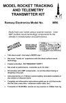
QUICK TONE CTCSS
SUB - AUDIBLE TONE
ENCODER DECODER
Ramsey Electronics Model No.
QT1
Caught in the maze of low frequency tones?
Looking for an easy way to update your rig with sub-audible
frequency tones? Let the Ramsey Quick Tone do the job for you
with digital accuracy!
•
Sharing a channel using (C)ontinuous (T)one (C)ontrolled (S)ubaudible (S)quelch or PL ? This is the complete circuit solution for
you!
•
Mini size quality circuit board designed to fit inside many
transceivers.
•
Add tone capability to access your favorite repeater with this easy
to assemble kit.
•
Encodes / decodes any of the 39 standard CTCSS tones with quartz
accuracy - no “tweaking” required!
•
Setup includes compete digital filtering of TX audio to eliminate
“talk off” interference from normal speech audio components.
•
Operates with any 5-15 VDC source - even includes an on-board
voltage regulator for noise free operation.
•
COMPLETE with hookup instructions and documentation to guide
you to a finished project that works first time - every time!
•
Easily bypassed for no-tone operation.
QT1 • 1
PARTIAL LIST OF AVAILABLE KITS:
RAMSEY TRANSMITTER KITS
• FM10A, FM25B FM Stereo Transmitters
• AM1, AM25 Transmitter
RAMSEY RECEIVER KITS
• FR1 FM Broadcast Receiver
• AR1 Aircraft Band Receiver
• SR2 Shortwave Receiver
• AA7 Active Antenna
• SC1 Shortwave Converter
RAMSEY HOBBY KITS
• SG7 Personal Speed Radar
• SS70A Speech Scrambler/Descrambler
• TT1 Telephone Recorder
• SP1 Speakerphone
• MD3 Microwave Motion Detector
• WEB1 Walking Electronic Bug
• ECG1 Heart Monitor
• PG13 Plasma Generator
• TFM3 Tri-Field Meter
RAMSEY AMATEUR RADIO KITS
• HR Series HF All Mode Receivers
• DDF1 Doppler Direction Finder Kit
• QRP Series HF CW Transmitters
• CW7 CW Keyer
• QRP Power Amplifiers
RAMSEY MINI-KITS
Many other kits are available for hobby, school, scouts and just plain FUN. New
kits are always under development. Write or call for our free Ramsey catalog.
QUICK TONE CTCSS ENCODER / DECODER INSTRUCTION MANUAL
Ramsey Electronics publication No. QT1 Revision 1.0
First printing: 1994
COPYRIGHT 1994 by Ramsey Electronics, Inc. 590 Fishers Station Drive, Victor, New York
14564. All rights reserved. No portion of this publication may be copied or duplicated without the
written permission of Ramsey Electronics, Inc. Printed in the United States of America.
QT1 • 2
Ramsey Publication No. MQT1
Price $5.00
KIT ASSEMBLY
AND INSTRUCTION MANUAL FOR
QUICK TONE CTCSS
SUB - AUDIBLE TONE
ENCODER DECODER
TABLE OF CONTENTS
Introduction to the QT1 ................. 4
How it Works ................................. 4
Schematic Diagram..................... 10
Parts list ........................................ 6
QT1 Assembly Instructions ........... 7
Parts Layout Diagram ................. 11
Hook-up Configurations ............... 12
Troubleshooting ........................... 16
Ramsey Kit Warranty ................... 19
RAMSEY ELECTRONICS, INC.
590 Fishers Station Drive
Victor, New York 14564
Phone (585) 924-4560
Fax (585) 924-4555
www.ramseykits.com
QT1 • 3
INTRODUCTION
With todays’ ever shrinking radio frequency spectrum, it has become
common place to “share” radio frequencies using a tone squelch
arrangement.
By transmitting a low frequency audio tone (sub-audible to the radio and
most of us) we can enable our transmitter to connect with receivers
specifically listening for the particular tone one happens to use. This will
eliminate much of the background “chatter” that may also be taking place on
a desired frequency.
This “tone squelch” arrangement is commonly used on many repeaters to
make them exclusive to the repeater club members only.
The problem is that many of the more reasonably priced rigs do not include
tone capabilities and that older equipment had no provision for this “modern”
squelching arrangement.
Their has been various ways to “update” older rigs for tone operations for
years, but these solutions were primitive, usually encoding or decoding a
single tone per unit and requiring extensive test equipment to align.
Enter MX-COM and one of their latest innovations in CTCSS technology.A
single 24 pin Integrated Circuit capable of encoding or decoding any of the
39 standard tone frequences available. That’s the heart of the Quick Tone
unit with some external setup and control parts.
QT1 THEORY OF OPERATION
You’ve probably already noticed that the QT1 kit doesn’t contain a whole lot
of components. The majority of the circuitry is contained inside the integrated
circuit with only a few external components that actually do the “brute force”
control of your transceiver.
The MX-COM IC is itself a testament to todays ever evolving digital circuitry
(including modern day compact disc players and the like) so without getting
too involved let’s take a look at what is being accomplished inside the IC.
Have a look at the schematic diagram (on page 10 of the instruction manual)
and follow along.
In the received audio path the radio’s audio is routed to the tone decoder
input of the chip. Depending on the sub-audible tone frequency selected
(using the programming inputs), as well as if that particular tone frequency is
present in the audio input, the RX decode output (pin 15) will go to a logic
level one for a valid tone decode. This output is then re-routed to the IC,
inverted, and used to drive an open collector muting circuit that “grounds” the
QT1 • 4
received audio until the sub-audible tone is detected. When that occurs,
transistor Q1 is turned off and the audio signal is free to drive a speaker or
headset output.
Another receive audio path is directly through the MX-COM. IC. The received
audio is routed through an internal high pass filter which digitally filters out any
low frequency CTCSS component in the received audio. Another advantage to
this internal audio route is that the tone squelch function can be easily
overridden by simply switching the Push-To-Listen (abbreviated PTL) pin of
the IC to a logic 1 condition. In this way it is easy to check the radio receivers
frequency for traffic that is not using your tone squelch setup.
The tone generation function is straightforward. When the Push-To-Talk line
(abbreviated PTT) is grounded, the IC generates the programmed sub-audible
tone. This audio signal is fed out pin 16, where a level adjustment
potentiometer is located. This low frequency audio component is available to
be added to the modulation input to the transmitter.
The TX audio path through the IC also makes use of the high pass filter to
remove any stray low frequency components of the audio to eliminate any
intermodulation product which could cause a “talk off” condition when
transmitting.
This previously mentioned “programming” is easily accomplished using jumper
blocks and we’ll discuss them in more detail when we’re actually ready to
select our tone frequencies. The same goes for the TX/RX audio inputs and
outputs, so lets get the “feel” of the circuit by building it before we discuss
actual hook ups and adding unnecessary confusion.
QT1 • 5
QT1 PARTS LIST
Please check the boxes after the components have been identified, and it is
also handy at this time to “sort” the like components into groups or bins (an
egg carton does nicely) to avoid using the wrong component during
assembly.
RESISTORS
3
1
1
1
1
10K ohm resistors [brown-black-orange] (R1,5,6)
470K ohm resistor [yellow-violet-yellow] (R2)
820K ohm resistor [grey-red-yellow] (R3)
1Meg ohm resistor [brown-black-green] (R4)
5K ohm trimmer potentiometer [black color marked 502] (R7)
CAPACITORS
1
1
1
1
8
33pF disc capacitor [marked 33] (C10)
68 pF disc capacitor {marked 68} (C8)
.01 uF disc capacitor [marked .01 or 103 or 10nF] (C11)
.1 uF disc capacitor [marked .1 or 104] (C9)
1 uF electrolytic capacitors (C1,2,3,4,5,6,7,12)
SEMICONDUCTORS AND INTEGRATED CIRCUITS
1
1
1
1
1
1N4148 diode [glass case with black band] (D2)
1N4002 diode [epoxy case marked 1N4002] (D1)
NPN small signal transistor [marked 2N3904] (Q1)
78L05 voltage regulator [marked 78L05] (VR1)
MX-COM MX165CP 24 pin IC (U1)
MISCELLANEOUS PARTS
1
1
6
1
1
Mini 1 MHz crystal [marked 1000J] (Y1)
12 pin jumper block
Pre formed jumper blocks (P0 - P5)
12” length of black, red, and white hookup wire
24 pin IC socket
QT1 • 6
RAMSEY Learn-As-You-Build KIT ASSEMBLY
There are numerous solder connections on the QT1 printed circuit board.
Therefore, PLEASE take us seriously when we say that good soldering is
essential to the proper operation of your kit!
•
•
•
•
Use a 25-watt soldering pencil with a clean, sharp tip.
Use only rosin-core solder intended for electronics use.
Use bright lighting; a magnifying lamp or bench-style magnifier may
be helpful.
Do your work in stages, taking breaks to check your work. Carefully
brush away wire cuttings so they don't lodge between solder
connections.
It is also important at this time to be honest about your kit building ability.
Even though we have made every attempt to make this kit and manual as
straight forward as possible, this kit may be too complex in a couple of ways.
•
•
In our attempt to make this unit small enough to fit inside many types
of transceivers, component spacing was “squeezed” considerably,
making this kit more difficult to assemble than many of our other hobby
kits.
This unit, when completed, needs to be interfaced with another piece of
electronic equipment. We at Ramsey cannot be held accountable for the
literally hundreds of individual radios and hookups necessary for proper
interface to them.
We will, of course, provide you with the best ideas for general hookups, but
the rest will be up to you. We regret that we cannot offer exact hook-up info
for the rig of your choice.
We have a two-fold "strategy" for the order of the following kit assembly
steps. First, we install parts in physical relationship to each other, so there's
minimal chance of inserting wires into wrong holes. Second, whenever
possible, we install in an order that fits our "Learn-As-You Build" Kit building
philosophy. This entails describing the circuit that you are building, instead of
just blindly installing components. We hope that this will not only make
assembly of our kits easier, but also help you to understand the circuit you’re
constructing.
For each part, our word "Install" always means these steps:
1. Pick the correct part value to start with.
QT1 • 7
2. Insert it into the correct PC board location.
3. Orient it correctly and follow the PC board drawing and the written
directions for all parts - especially when there's a right way
and a wrong way to solder it in. (Diode bands, electrolytic
capacitor polarity, transistor shapes, dotted or notched ends
of ICs, and so forth.)
4. Solder all connections unless directed otherwise. Use enough
heat and solder flow for clean, shiny, completed connections.
Now, let's get building!
Since you may appreciate some “warm-up” soldering practice as well as a
chance to put some “landmarks” on the PC board, we’ll first install some less
crowded components. This will also help us to get acquainted with the up down, left - right orientation of the circuit board. Remember that the
components will be mounted on the “component” side of the circuit board
and soldered on the “solder” side of the circuit board, the side with the
printed circuit traces.
1. Install C7, 1 uF electrolytic capacitor. Electrolytic capacitors are
polarized with a (+) and a (-) lead and must be installed in the correct
orientation. Ordinarily, only the negative side is marked on the capacitor
body with a dark band and the (-) sign clearly shown, while PC boards
will usually show the (+) hole location. Use care to ensure proper
polarity. See the parts diagram for proper placement. The capacitor
should fit snugly down to the PC board.
2. In the same manner, install electrolytic capacitors C2, 5 and 6, all 1 uF
in value. Watch the polarity of each! Notice how all the caps are facing in
the same direction to avoid confusion while installing. These components
act as “DC blocks”; that is, they allow the audio signal through them, but
will not allow any DC voltage to reach the MX165CP IC.
3. Now the fun part! Install the 24 pin IC socket in the U1 position. Notice
that one end of the socket is marked with a notch; orient it as shown in
the parts layout as to help when installing the IC. Solder one pin at a
time and take extra caution as not to “bridge” solder between two or
more pins. Now, identify the 24 pin IC (labeled MX165CP). Notice that
one end of the chip is also marked with a dot, notch, or band. Be sure to
orient this end as shown in the parts diagram. Gently insert this IC into
the socket. Be careful not to bend any of the leads underneath the
socket while installing this part.
4. Identify and install disc capacitor C11, a .01 uF disc (marked .01 or
103 or 10nF). Be sure to push this part snug to the PC board.
QT1 • 8
5. Identify R2, 470K ohm (yellow-violet-yellow). Notice how this
component will be mounted “standing up”.
To mount this component properly, you’ll
need to form the leads as shown. Then
slip the leads though the circuit board, and
solder.
6. Install R3, 820K ohm (grey-red-yellow).
Notice that this component is also
mounted “standing”. By mounting the components this way they occupy
less room on the PC board, making our finished project as small as
possible.
7. Install D2, a 1N4148 type diode. Notice that one end of this
component is marked with a band. Diodes are “polarized”; that is, like a
battery, they have a positive (+) and negative (-) side. Be sure to follow
the parts diagram carefully and orient the banded end as shown. Use
caution when forming the leads of the component as not to fracture the
glass component.
8. Install C9, .1uF disc (marked .1 or 104). Remember to push the
component as close as mechanically possible before soldering.
9. Install R5, 10K ohm (brown-black-orange).
10. Install R7, the 5K ohm trimmer potentiometer (black color, marked
502M). Gently rock it into place on the PC board and solder securely.
11. Install C12, 1uF electrolytic capacitor. Watch that polarity! See the
parts diagram for correct placement.
12. Install R6, 10K ohm (brown-black-orange). Notice that this
component is mounted “standing up”.
13. Identify Q1, a 2N3904 NPN transistor (marked 3904). When installing
Q1, observe correct placement of the flat side. Press the transistor
snugly into the PC board so that only a minimum amount of wire lead is
exposed above the board. In soldering, do not be afraid of using enough
heat to make a good solid connection.
Hang in there, only a few parts to go. Check your solder connections up to
now and repair any “less than perfect” connections.
14. Install the jumper pin block, P0-P5. This will be used as the
“programming” input to your MX165CP IC. Carefully solder each
connection and watch out for solder bridges.
15. Install C10, 33pF disc capacitor (marked 33 or 33K).
16. Form and install R4, a “stand up” 1 Meg ohm (brown-black-green).
17. Identify the crystal in the rectangular blue case marked 1000J. Install
in the Y1 position. You don’t have to worry about polarity; this component
will work either way.
QT1 • 9
18. Install C8, 68pF disc capacitor (marked 68 or 68K).
19. Install C1, 1uF electrolytic capacitor. Ensure proper polarity.
20. Identify and install diode D1, 1N4002 (epoxy bodied component with
stripe, marked 4002). Be sure to face the band as shown in the parts
diagram. Mount it “standing up”, using care to ensure proper polarity.
QT1 • 10
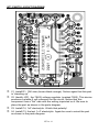
QT1 PARTS LAYOUT DIAGRAM
21. Install R1, 10K ohm (brown-black-orange). Notice again that this part
is “standing up”.
22. Identify VR1, the 78L05 voltage regulator (marked 7805). This device
produces a stable 5 volt reference for the circuit. Notice that this
component has a “flat” side with the writing imprinted on it. Be sure to
place the part as shown in the parts diagram.
23. Install C4, 1uF electrolytic. Watch that polarity!
24. Install C3, the last 1 uF electrolytic. Again be sure to orient the part
as shown in the parts diagram.
QT1 • 11
25. Install a short length of red hookup wire to the +V connection.
26. Install a short length of black hookup wire to the -V connection.
CONGRATULATIONS
You have just completed your QT1 Sub Audible Tone Encoder/Decoder.
Take a well deserved break now. Give your eyes a rest. When you return, be
sure to check over your work on the entire circuit board. Energizing the
circuit board with solder “bridges” or misplaced components can damage
your kit. A few well spent minutes now can save hours of troubleshooting
and dollars in replacements for burned out parts.
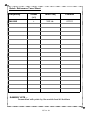
INITIAL HOOK UP AND TESTING
While we know that you’re probably anxious to “fire up” your kit, first we’ll
have to program a tone frequency for the unit to generate and decode. We’ll
also need to connect our circuit to the “outside world” to test.
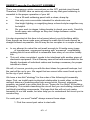
Hopefully, the following board description will help in deciphering the
abbreviations that were used on the circuit board.
(+)Voltage
Input
( - ) Voltage
Input (GND)
Open to Listen (Tone
Squelch Override)
Receive and
Transmit Audio
Inputs
P0-P5
Programming
Inputs
(See Chart)
M u t e
Receive
Receive and
Transmit Audio
Outputs
=
Mute
PTT = Push To Talk
0 = Transmit
Out = CTCSS
Tone Output
Tone Level Adjust
QT1 • 12
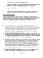
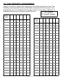
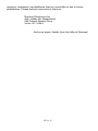
QT1 TONE FREQUENCY PROGRAMMING
Finally, it’s time to set the tone frequency on the Ramsey Quick Tone. The
following chart describes the combinations of jumpers for the various tone
frequencies. An ‘0’ indicates that a jumper block is not present, while an ‘X’
indicates that there is a jumper across the pins.
0 = No Jumper
X = Install Jumper
TONE
FREQ
(Hz)
P5
P4
P3
P2
P1
P0
67.0
0
0
0
0
0
0
69.3
0
0
0
X
X
0
71.9
X
0
0
0
0
0
74.4
0
0
0
0
0
X
77.0
X
X
0
0
0
0
79.7
0
0
0
0
X
0
82.5
X
0
0
0
0
85.4
0
0
0
0
88.5
X
X
0
91.5
0
0
94.8
X
97.4
TONE
FREQ
(Hz)
P5
P4
P3
P2
P1
P0
141.3
X
X
0
X
X
X
146.2
X
0
X
0
0
0
151.4
X
X
X
0
0
0
156.7
X
0
X
0
0
X
159.8
0
0
X
X
X
0
X
162.2
X
X
X
0
0
X
X
X
167.9
X
0
X
0
X
0
0
0
X
173.8
X
X
X
0
X
0
0
X
0
0
179.9
X
0
X
0
X
X
0
0
0
X
0
183.5
0
0
X
X
0
X
0
0
0
X
0
X
186.2
X
X
X
0
X
X
100.0
X
X
0
0
X
0
189.9
0
0
X
X
0
0
103.5
X
0
0
0
X
X
192.8
X
0
X
X
0
0
107.2
X
X
0
0
X
X
196.6
0
0
X
0
X
X
110.9
X
0
0
X
0
0
203.5
X
X
X
X
0
0
114.8
X
X
0
X
0
0
210.7
X
0
X
X
0
X
118.8
X
0
0
X
0
X
218.1
X
X
X
X
0
X
123.0
X
X
0
X
0
X
225.7
X
0
X
X
X
0
127.3
X
0
0
X
X
0
233.6
X
X
X
X
X
0
131.8
X
X
0
X
X
0
241.8
X
0
X
X
X
X
136.5
X
0
0
X
X
X
250.3
X
X
X
X
X
X
QT1 • 13
Select and program the desired tone frequency (e.g. 100.0 Hz = 01101 =
Jumper installed in P5, P4, and P1).
Connect the unit to a suitable power source (5 - 15VDC).
Connect the PTT line to circuit ground while observing the the “OUT”
connection. You should be able to detect the tone output (using an
oscilloscope) and vary its amplitude using R7.
Disconnect the PTT line; ground the ‘OTL’ (Open To Listen) pin, and
connect an audio signal generator (or equivalent) to the ‘RX IN’ audio
input pin. While observing the decode output pin (pin 13 of the MX-COM
165CP) with a DC voltmeter you should see the output go low as the
desired frequency is met. Note, however, that the chip’s filter is
extremely sharp (probably more precise than your signal generator’s
dial), so patiently swing the audio oscillator control near the desired
frequency until you see it decode.
TYPICAL HOOKUP INSTRUCTIONS
A word of caution to begin with: Now that your QT1 kit has been tested,
you’re moving into maybe the most challenging part of the assembly, the
interface of the tone detector with the radio. As a general rule we suggest
that you have a copy of the schematic for the transceiver that you wish to
interface with. If you’re not sure, call the radio’s manufacturer and request
one. Please do not risk damage to your transceiver by haphazardly making
connections to your radio. Be sure to unplug all power from the rig and
double check each connection before applying power to either the radio or
the QT1.
Here are some general hook-up block diagrams for most any rig. Don’t let
this big chip scare you - remember, all we have to do is generate or detect
the presence of a tone!
Hook-up #1: Transmit Tone Encode Only
This is the easiest way to get into your favorite repeater. After configuring
your QT1 for the proper tone frequency, simply connect the CTCSS tone
output to the modulation input of the transceiver.
The PTT line of the QT1 should be connected to ground (for continuous tone
generation) or to the radio’s PTT line (for tone generation only on transmit). If
you are connecting to the PTT line, please note that it must go low, or switch
to ground, when in transmit mode.
QT1 • 14
(or tie to ground)
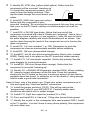
Hook-up #2: Tone Encode and Receive Decode
This hook-up allows muting of the receive audio until the proper tone is being
received. The open collector “RX MUTE” is tied to the high side of the
volume control pot. Following are a few “pro’s and con’s” concerning this
type of configuration.
1. This interconnection requires no disabling of the original audio path
inside the receiver to function. You can even hook-up the unit with ‘clip’
leads to check its functioning.
2. Be sure to ‘pick-off’ the audio just after the receiver detector - before the
audio is limited to exclude low frequency signals.
3. The major disadvantage of this configuration is that the “OTL” line will
not control the RX MUTE output. The only way to disable the tone
squelch is to remove power from the entire circuit board.
QT1 • 15
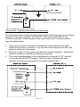
The next diagram shows a more involved way of interfacing your kit. This
configuration more fully utilizes the MX-COM. IC and its more advanced
features.
1. This connection used the “built in” audio filtering provided by the MXCOM. chip for superior audio quality, both on receive and transmit.
2. In this configuration you may also trip the mic hanger in transmit mode to
eliminate any unwanted “squelch tail” that is present.
3. The bad news is that you have to physically break the audio path at
some point inside the transceiver. Although this is probably not too
difficult, use extreme caution as with in any modification. Similarly, The
TX audio should be routed to the TX IN connection. The TX OUT
connection should then be connected to the modulation adjustment
potentiometer inside the transmitter.
TROUBLESHOOTING INSTRUCTIONS
While we had hoped that it wouldn’t come to this, if you are having trouble
with your tone board, here are a few suggestions.
Use a methodical, logical troubleshooting technique. Most problems can be
solved using common sense. A volt-ohm meter and a clear head are usually
all that are needed to correct any problem.
With the majority of the circuit being controlled by a single chip, rest assured
that it was double checked for quality here at the factory.
Here are some common voltage measurements to test for proper operation.
The interconnections between various rigs and the tone board may cause
some strange results to occur. Try to isolate the problem one stage at a
time. Does the board encode and decode? Does the PTT line go to 0V on
xmit? Usually a big problem boils down to one or two smaller, easier solved
glitches.
Please understand that it is nearly impossible for us to “trouble-shoot” over
the phone, especially with interfacing problems to the hundreds of rigs out
there. We will give it our best shot, if you mail us a schematic and block
diagram of your rig. Usually these type of problems can be solved bouncing
around suggestions on your repeater with the local radio “guru”, so you may
want to give that a try first.
CONCLUSION
We sincerely hope that you have enjoyed the construction and use of this
Ramsey Kit. As always, we have tried to compose our manual in the easiest,
most “user friendly” format that is possible. As our customers, we value your
QT1 • 16
opinions, comments, and additions that you would like to see in future
publications. Please submit comments or ideas to:
Ramsey Electronics Inc.
Attn. Hobby Kit Department
590 Fishers Station Drive
Victor, NY 14564
And once again, thanks from the folks at Ramsey!
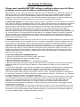
QT1 • 17
Quick Reference Tone Sheet
Frequency
146.880
Offset
(+/-)
Tone Freq
Preload
+
100 Hz
01101
RAMSEY KITS ...
Assembled with pride by the worlds best kit builders
QT1 • 18
The Ramsey Kit Warranty
Please read carefully BEFORE calling or writing in about your kit. Most
problems can be solved without contacting the factory.
Notice that this is not a "fine print" warranty. We want you to understand your rights and ours too! All
Ramsey kits will work if assembled properly. The very fact that your kit includes this new manual is
your assurance that a team of knowledgeable people have field-tested several "copies" of this kit
straight from the Ramsey Inventory. If you need help, please read through your manual carefully, all
information required to properly build and test your kit is contained within the pages!
1. DEFECTIVE PARTS: It's always easy to blame a part for a problem in your kit, Before you conclude
that a part may be bad, thoroughly check your work. Today's semiconductors and passive components
have reached incredibly high reliability levels, and its sad to say that our human construction skills
have not! But on rare occasion a sour component can slip through. All our kit parts carry the Ramsey
Electronics Warranty that they are free from defects for a full ninety (90) days from the date of
purchase. Defective parts will be replaced promptly at our expense. If you suspect any part to be
defective, please mail it to our factory for testing and replacement. Please send only the defective part
(s), not the entire kit. The part(s) MUST be returned to us in suitable condition for testing. Please be
aware that testing can usually determine if the part was truly defective or damaged by assembly or
usage. Don't be afraid of telling us that you 'blew-it', we're all human and in most cases, replacement
parts are very reasonably priced.
2. MISSING PARTS: Before assuming a part value is incorrect, check the parts listing carefully to see
if it is a critical value such as a specific coil or IC, or whether a RANGE of values is suitable (such as
"100 to 500 uF"). Often times, common sense will solve a mysterious missing part problem. If you're
missing five 10K ohm resistors and received five extra 1K resistors, you can pretty much be assured
that the '1K ohm' resistors are actually the 'missing' 10 K parts ("Hum-m-m, I guess the 'red' band
really does look orange!") Ramsey Electronics project kits are packed with pride in the USA. If you
believe we packed an incorrect part or omitted a part clearly indicated in your assembly manual as
supplied with the basic kit by Ramsey, please write or call us with information on the part you need
and proof of kit purchase.
3. FACTORY REPAIR OF ASSEMBLED KITS:
To qualify for Ramsey Electronics factory repair, kits MUST:
1. NOT be assembled with acid core solder or flux.
2. NOT be modified in any manner.
3. BE returned in fully-assembled form, not partially assembled.
4. BE accompanied by the proper repair fee. No repair will be undertaken until we have received the
MINIMUM repair fee (1/2 hour labor) of $25.00, or authorization to charge it to your credit card
account.
5. INCLUDE a description of the problem and legible return address. DO NOT send a separate letter;
include all correspondence with the unit. Please do not include your own hardware such as nonRamsey cabinets, knobs, cables, external battery packs and the like. Ramsey Electronics, Inc.,
reserves the right to refuse repair on ANY item in which we find excessive problems or damage due
to construction methods. To assist customers in such situations, Ramsey Electronics, Inc., reserves
the right to solve their needs on a case-by-case basis.
The repair is $50.00 per hour, regardless of the cost of the kit. Please understand that our technicians
are not volunteers and that set-up, testing, diagnosis, repair and repacking and paperwork can take
nearly an hour of paid employee time on even a simple kit. Of course, if we find that a part was
defective in manufacture, there will be no charge to repair your kit (But please realize that our
technicians know the difference between a defective part and parts burned out or damaged through
improper use or assembly).
4. REFUNDS: You are given ten (10) days to examine our products. If you are not satisfied, you may
return your unassembled kit with all the parts and instructions and proof of purchase to the factory for
a full refund. The return package should be packed securely. Insurance is recommended. Please do
not cause needless delays, read all information carefully.
QT1 • 19
Ramsey Quick Tone CTCSS TONE
ENCODER DECODER
Quick Reference Page Guide
Introduction to the QT1 ............................. 4
How it works .............................................. 4
Schematic diagram ................................. 10
Parts list .................................................... 6
QT1 Assembly instructions ....................... 7
Parts Layout diagram .............................. 11
Hook-up configurations ............................12
Troubleshooting .......................................16
Ramsey kit warranty ................................19
REQUIRED TOOLS
• Soldering Iron Ramsey WLC100
• Thin Rosin Core Solder Ramsey RTS12
• Needle Nose Pliers Ramsey MPP4 or
RTS05
• Small Diagonal Cutters Ramsey RTS04
<OR> Technician’s Tool Kit TK405
TOTAL SOLDER POINTS
100
ESTIMATED ASSEMBLY
TIME
Beginner............... 2.0 hrs
Intermediate ......... 1.5 hrs
Advanced ............. 1.0 hrs
ADDITIONAL SUGGESTED ITEMS
• Holder for PC Board/Parts Ramsey HH3
• Desoldering Braid Ramsey RTS08
• Digital Multimeter Ramsey M133
Price: $5.00
Ramsey Publication No. MQT1
Assembly and Instruction manual for:
Quick Tone CTCSS Encoder / Decoder
RAMSEY MODEL NO. QT1
RAMSEY ELECTRONICS, INC.
590 Fishers Station Drive
Victor, New York 14564
Phone
(585) 924-4560
Fax
(585) 924-4555
www.ramseykits.com
QT1 • 20
This Quality Electronics
Kit was designed and
packed in the USA