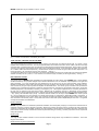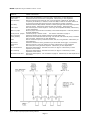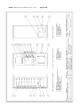
1
MUSTANG COMMUNICATIONS MACRO SYSTEM AMPLIFICATION EQUIPMENT INSTALLATION, COMMISSIONING & MAINTENANCE HANDBOOK Issue No.8 SCOPE OF THIS ISSUE: Black fascia models: M8/MD M1008/D M2508/D M100/SD M250/SD Input modules Standard options M1008 M2508 M100/S M250/S Mustang Communications Ltd Eastfield Industrial Estate Scarborough England YO11 3UT Telephone U.K. 01723 582 555 Telephone International 44 1723 582 555 Fax U.K. Fax international Email Web 01723 581 673 44 1723 581 673 [email protected] www.mustang.co.uk MACRO amplification range installation manual. Issue 8 Page 2 MACRO amplification range installation manual. Issue 8 Author: M. R. Tetley M. Inst. S. C. E. ___________________________________________________________________ INDEX ............................................................................................................................... PAGE Introduction ....................................................... ....................................................... 5 - The Company and its quality statement ......................................... 5 - The MACRO system concept and applications ............................. 5 General specifications ............................................. ................................................. 6 Front panel controls and indicators ................................ .......................................... 6 Tone control & Master gain adjustment ............................. ..................................... 7 Input module system ............................................... ................................................ 7 - module installation .......................................................................... 7 - module range .................................................................................. 7 - module features, general specifications and DIL switch settings . 7 - input connections ............................................................................ 10 - module adjustments ........................................................................ 10 Priority input facilities .......................................... ..................................................... 10 - priority/passive setting of modules ................................................. 12 - priority memory ............................................................................... 12 Pre-announcement chimes ............................................ .......................................... 12 Mixer facility connections - 0dB signal access point .............. ................................. 12 - 0dB signal in/out access for mixers & mixer amplifiers ................. 12 - input connections for slave amplifiers ............................................ 12 - tape recording ................................................................................. 13 - tape playback .................................................................................. 14 - interconnection of several amplifiers ............................................. 14 Power amplifier module ............................................ ............................................... 14 Loudspeaker output ................................................. ................................................ 15 - typical loudspeaker load arrangements ......................................... 15 Auxiliary output connections ...................................... ............................................. 16 - Priority controlled DC current sinks ................................................ 16 - Chime duration monitor sinks (CDM) ............................................. 17 - 100V line output .............................................................................. 17 - 24V DC supply ................................................................................ 17 Combining the loudspeaker outputs of two or more amplifiers .................................. 17 Power supply ...................................................... ..................................................... 17 - AC mains power input ..................................................................... 17 - DC power input ................................................................................ 17 - Systems powered by both AC and DC supplies ............................ 19 - Main ON-OFF front panel switch .................................................... 19 - POWER indicator LED .................................................................... 19 - OUTPUT ERROR indicator LED .................................................... 19 - SUPPLY STATUS indicator LED .................................................... 19 - Power supply failure monitoring ..................................................... 19 - Power supply change-over ............................................................. 19 - Battery charger circuit ..................................................................... 19 Earthing & hum loops .............................................. ................................................ 20 Factory fitted options ............................................ ................................................... 21 - Automatic level control ................................................................... 21 - Balanced line input for M/100 and M/250 slave amplifiers ............ 21 - Line surveillance ............................................................................. 22 Installation ...................................................... ......................................................... 22 - selection of signal input cables ...................................................... 22 - selection of loudspeaker cable ....................................................... 22 - fitting Locking DIN connectors ....................................................... 22 - siting ................................................................................................ 23 - rack mounting .................................................................................. 23 - heatsink temperature ...................................................................... 23 - ventilation ........................................................................................ 23 - interference ..................................................................................... 23 - removal of control knobs ................................................................ 23 - checklist .......................................................................................... 23 Fuses .......................................................... ............................................................ 24 Repairs and maintenance ........................................... ............................................ 24 - top cover removal ........................................................................... 24 - removal of main pre-amplifier circuit board ................................... 24 Warranty .......................................................... ....................................................... 24 Faults - symptoms and check-list ................................. .......................................... 25 Electromagnetic compatibility (EMC) directive 89/336/EEC and amendment directive 92/31/EEC This equipment has been designed and manufactured to the highest standards. If connected and operated as set out in this manual, there should be no Electromagnetic Compatibility problems. If any aspect of operation gives rise to concern, then please contact the manufacturer for advice. Page 3 MACRO amplification range installation manual. Issue 8 PAGE Table 1 Table 2 The current range of input modules Module adjustments and settings 8 11 Fig. Fig. Fig. Fig. Fig. Fig. Fig. Fig. Fig. Fig. Fig. Fig. Location of Treble, Bass, and Master gain controls Input connector pin identification Location of priority sequence setting switches Mixer facility connections for standard locking DIN connector Mixer facility connector pin identification Tape record and playback connections Interconnection of several amplifiers Power amplifier module fixings and adjustments Typical applications of the Current Sink feature Priority connections for multiple amplifier systems AC & DC supply connections and monitoring Balanced line input connections 7 10 11 13 12 13 14 15 16 18 20 20 1 2 3 4 5 6 7 8 9 10 11 12 General Block schematic diagram Typical priority control and page-only arrangements Typical loudspeaker circuits Chassis layout & main component identification Locations of module adjustments and fuses Page 4 APPENDIX A APPENDIX B APPENDIX C APPENDIX D APPENDIX E MACRO amplification range installation manual. Issue 8 INTRODUCTION Thank you for purchasing this unit. We are confident that you have made a wise decision, and that you will have many years of trouble-free operation. Considerable care has been taken during the design and manufacturing processes to ensure your entire satisfaction and naturally, we would hope that the unit will perform to our design expectations, though this will be possible only if the installation is in line with professionally accepted standards and techniques. This manual is intended, therefore, to ensure that both the installer and operator have all the necessary information to enable them to install, commission, and operate the unit in the most effective manner. We hope you will find the manual helpful, and easy to read. The Company and its quality statement Mustang Communications, is the manufacturing mark of equipment manufactured by Mustang Communications Limited, of Scarborough, England. The company is independent, wholly British, and dedicated to the manufacture and distribution of highreliability, high performance public address and associated control equipment. Mustang Communications was first registered in 1966, in England. The Company undertakes to manufacture equipment to the highest standards of workmanship and performance. Our Quality Assurance scheme operates to, or exceeds, the standards set out in British Standard BS.5750, Part 2. 1987 or European standard ISO.9002. If you have cause to doubt at any time that the manufacture, or distribution does not comply, then you are invited to write to us with your comments, which will be most welcome. Please address your correspondence to The Engineering Director. The MACRO system concept and applications MACRO System is a comprehensive range of AC mains and AC mains/24V DC amplification, controls and surveillance units and associated peripherals, designed for use by emergency services and high integrity communication and alarm systems, manufactured to the highest standards of electronic and mechanical performance and with Quality Assurance to British Standard BS.5750 AC/ DC equipment is designed to operate normally from 220/240V AC mains, with the capability to operate indefinitely, and without loss of any facilities, from a standby DC power source (battery system) in the event of mains failure. Full compatibility within the MACRO range is assured, thus easing system design and enabling fully integrated systems to be specified using standard MACRO components and options. The current manufacturing programme features a variety of 8 input mixers, 100 Watt and 250 Watt 8 input mixer amplifiers and corresponding slave amplifiers, all offered in AC mains only or AC/DC format. AC/DC units provide full AC and DC power integrity monitoring and indication, and all except mixers feature a trickle-charge circuit as standard. Mixer input versions accommodate up to 8 modules, selected from the comprehensive range of microphone, line input and alarm tone generator modules. These are plugged into an internal mother board system which generates 8 levels of ladder priority, equal access priority or any combination of both. Priorities may be set up easily at system commissioning stage. The module circuits feature various aspects of memory trigger, priority sinking for use with MACRO zone controllers, remote relays, system busy indicators etc., and such functions are taken to a rear D connector. Each module is associated with a front panel gain control whose knob and spindle may be removed at commissioning stage and replaced by a discreet blanking plug to discourage unauthorised tampering. Line driver and stabilised low voltage PSU facilities are also on plug in modules. Treble and bass tone, and master gain adjustments are internal and presettable. The amplifier power output stage is in the form of a self contained bolt-on pluggable module for ease of maintenance, and pre-set adjustment for sensitivity, overload threshold, and bias are featured. Output devices are very robust FETs and errors on the module are notified by a front panel LED. Other front indicators are a segmented bargraph output VU, AC (and DC where appropriate) supply input status monitoring LED, and a power LED. A soft-start DC switch on circuit is employed. The transformers employed in MACRO amplifiers are in-house designed and manufactured to the highest standards of tolerance and quality to maximise the efficiency of the electronics. Mechanically, MACRO amplifiers utilise a robust ventilated steel casing, powder coat painted, and screen printed, with nut and bolt fastenings throughout. Connectors are tough locking DIN as standard for signals, D connector for auxiliary control functions, IEC mains, and military specification 97 series DC input. By use of the optional extra BRK-30 rack mount kit, the front fascia is converted tol fit a standard 3U 19" panel space. By appropriate choice of input modules, the MACRO range of equipment will perform with outstanding results in a multitude of applications, and a few only are listed under:Factory paging, time signals and alarm amplification Retail stores paging and background music Theatre show relay and prompt calls etc. Multi-zone exclusive paging using one amplifier Shopping centre automatic spot announcements and security paging etc. Zoned fire alarm systems In use the amplifiers will give trouble free and accurate performance, and failure or partial failure is likely to be a result of external problems with loudspeaker or input cabling etc. The following pages will provide a guide to setting up, operation and maintenance of the amplifier, but in case of difficulty it would be advisable to consult a qualified dealer or the manufacturer. Page 5 MACRO amplification range installation manual. Issue 8 GENERAL SPECIFICATIONS MIXER AMPLIFIERS Input channels Input channel level & response Treble & Bass adjustment Power output (Watts RMS contin.) Current sinks Auxiliary DC output Mixer facility level Power amplifier input Power amplifier power freq. resp. Loudspeaker matching AC mains voltage requirement AC mains load 24V DC supply input (22-28V) DC quiescent consumption (approx) Trickle charger output SLAVE AMPLIFIERS Power output (Watts RMS contin.) Audio input level Power amplifier power freq. resp. M1008 M1008/D M2508 M2508/D M100/S M100/SD M250/S M250/SD 8 8 dependent upon input modules fitted ± 12dB @ 100Hz & 10kHz ref.1kHz 100 250 250mA maximum, each channel module nominally +24V. 1A fused, +35V unloaded. 775mV nominal. 0dBV 775mV , 0dBV @ 10k ohms -3dB @ 20Hz & 20kHz ref. 1kHz, low imp -3dB @ 20Hz & 15kHz ref. 1kHz, 100V 100V/50V line balanced Nominally 220-240V 50-60Hz +5% -15% 300VA 600VA 6 Amp 18 Amp 350mA 350mA 27.6V @ 1.5A maximum, pulsed 0.5 sec Loudspeaker matching AC mains voltage requirement AC mains load 24V DC supply input (22-28V) DC Quiescent consumption (approx) Trickle charger output 100 250 775mV, 0dBV @ 10k ohms -3dB @ 20Hz & 20kHz ref. 1kHz, low imp -3dB @ 20Hz & 15kHz ref. 1kHz, 100V 100V/50V line balanced Nominally 220-240V 50-60Hz +5% -15% 300VA 600VA 6 Amp 18 Amp 250mA 250mA 27.6V @ 1.5A maximum, pulsed 0.5 sec Input channels Input level & response Treble & Bass adjustment Current sinks Auxiliary DC output Audio output level AC mains input 24V DC supply input (22-28V) DC quiescent consumption (approx) 8 dependent upon input modules fitted ± 12dB @ 100Hz & 10kHz ref.1kHz 250mA maximum, each channel module nominally +24V , fused 1A, +35V unloaded 775mV nominal. 0dBV 220-240V 50-60Hz +5% -15% Approx 10-15VA 250mA (module dependent) 150mA MIXERS M8/MD FRONT PANEL CONTROLS & INDICATORS By design, user accessible controls are kept to a minimum to avoid inadvertent maladjustment which could render the system ineffective. Each input channel of a MACRO mixer or mixer-amplifier may be adjusted for gain by using the front panel controls. Should the commissioning engineer deem it prudent, he may remove any of the complete control knob/spindle assemblies, after adjustment is complete, simply by pulling the knob. The resulting holes may then be blanked off using the blanking plugs supplied. The controls may be refitted at any time subsequently. Slave amplifiers to standard specification are not fitted with a front gain control. An rocker power switch controls AC power input (and if applicable, DC power input simultaneously). A series of LED indicators provides a simple means of assuring the user of correct amplifier operation. A 10 segment ladder gives an indication of output level expressed in decibels - i.e. dB relative to maximum output amplitude. Under normal programme conditions this will fluctuate between the extreme left and extreme right segments in accordance with the amplitude of the programme at any particular instant. No segment is illuminated when the amplifier output is zero. If the illuminated segment is predominantly to the extreme right (maximum) then it is likely that the amplifier is being over-driven and that the resulting sound will be distorted on peaks. Reduce the corresponding front input gain control accordingly. A fast attack/slow decay circuit is used to drive the display so that amplitude peaks are recognised. Three further LEDs indicate the status of the AC and/or DC power supply in use, the ERROR status of the power amplifier module where appropriate, and confirmation that the unit is switced on. For further details see page 19. Page 6 MACRO amplification range installation manual. Issue 8 Fig. 1 Location of Treble, Bass, and Master gain controls TONE CONTROL & MASTER GAIN ADJUSTMENT Tone control facilities are provided on the line driver module, type TB.6 which is located at second right, on a mixer or mixer amplifier when viewed from the front. Two trimmer potentiometers are located at the bottom of the module, just above the edge connection tabs. Viewed from the front, the nearest is the bass adjustment and the furthest is the treble. Each controls a cut & lift correction circuit with the central position of the rotator giving nominally flat response. At the extremities of rotation, the corrections are ± 12dB at 100Hz and 10kHz respectively. Rotate controls clockwise to increase the gain at bass or treble frequencies. On leaving the factory, the controls will be set for level response. See Fig. 1 A conventional master level control is featured on the mother PCB between the line driver module (TB.6 etc) and the pre-amplifier stabiliser module (PS.9 etc.) next to it. This control is set to maximum (fully clockwise) on leaving the factory. See Fig. 1 INPUT MODULE SYSTEM The general accent of MACRO system amplification is towards flexibility of system design. Each MACRO mixer or mixer amplifier will accommodate up to 8 purpose designed input modules selected from over 30 variations of pre-amplifiers, tone signal and alarm generators. Any of the modules from the published list may be used in any of the 8 input channels of the amplifiers. Modules are available to accept audio input signals for low-level processing from all known audio sources. Depending on type, each module may be given a priority within the amplifier as described below. The chosen group of modules is set up within the amplifier by the commissioning engineer to exhibit the required sequence of priorities for the specific sound system, and further individually adjusted on the module for sensitivity, tone frequency, etc. These system adjustments are not directly accessible to the user, who is confined to the front panel controls. Modules may be changed, removed, or adjusted at any time without disturbance to the general operation of the system. Where priority sinking is featured, two alternative sinks are offered simultaneously - Any priority, and Individual input priority. Therefore, external circuits such as relays, lamps, MACRO zone control systems etc., may be triggered by any input channel or a specific input channel (or channels) by appropriate auxiliary connections. A Chime Duration Monitor circuit, where fitted, gives clearance-to-speak information for paging systems via the CDM current sink connection of the auxiliary output. Priority sinks and CDM current sinks operate independently of each other. The general concepts are illustrated in APPENDIX B Module installation MACRO range amplification is intended for permanent installation, and consequently the plug-in concept of the modules does not anticipate continuous or regular changing of modules. Whilst this is possible, the edge connector contacts may wear prematurely and become intermittent and unreliable. Modules are located between vertical supports immediately behind the respective front panel volume control, and only moderate force will be required when fitting or removing. DO NOT put pressure on the components during this operation. Module range The range of input modules extends to cover all common functions though others may be added to suit demand. The current range is shown below. Module features & general specifications Page 7 MACRO amplification range installation manual. Issue 8 MICROPHONE & LINE INPUT MODULES M240 M260 M280 L240 L270 L300 L330 L340 Universal low impedance microphone input, transformer balanced, and phantom supply. Low impedance transformer balanced microphone input with chimes and phantom supply. Low impedance transformer balanced microphone input, audio operated priority, and phantom supply Universal line input, transformer balanced, 50mV - 100V Universal line input, transformer balanced, 50mV - 100V, chimes. Universal line input, transformer balanced, 50mv - 100V, audio activated priority. Auxiliary unbalanced line input, 75mV- 2.0V, priority/passive Auxiliary unbalanced line input, 75mV - 2.0V, priority, chimes (no CDM) E260 RIAA equalised 5mV @ 50K for magnetic phono cartridge Flat response, 80mV to 1V for ceramic phone cartridge NON-PRIORITY MODULES TONE GENERATOR MODULES T260 T270 T300 T320 Repeating gongs with timer, priority hold & memory Multi function alarm tone generator. Provides dee-dah, whoop, warble, time pips, dashes, and continuous. Momentary triggering or with timer, priority hold & trigger memory. Trimphone telephone simulator, momentary triggering Triple chimes with timer, priority hold, & memory Table 1 The current range of input modules Module features, general specifications & DIL switch settings MICROPHONE INPUT MODULES Transformer or Electronic balanced Priority only or priority/passive option Priority controlled current sink Chimes & Chime Duration Monitor sink Phantom DC supply Audio activated priority (VOX) Bass cut facility M240 T PP 4 M260 M280 4 4 4 4 T PO 4 4 4 4 4 T PO 4 GENERAL SPECIFICATIONS - MICROPHONE INPUT MODULES Input mode Sensitivity range Input impedance Frequency response -3dB points ref 1kHz Bass cut response Signal to noise ratio Input overload capability Sink capability (mA max. continuous) Phantom supply VOX delay Transformer balanced, centre tap by-passed to Audio 0V 100uV to 100mV Suitable for 200 ohm microphones 60Hz - 20kHz -3dB @ 300Hz -6dB @ 200Hz 66dB minimum 40dB minimum 250mA nominally +20V via 1k0 3 seconds maximum DIL switch 1 DIL switch settings for Microphone input modules M240/260/280 100uV - 1mV sensitivity 1mV - 10mV sensitivity 10mV - 100mV sensitivity Phantom supply enable (all sensitivities) on LINE INPUT MODULES L240 Transformer input or unbalanced Priority only or Priority/passive switchable Sensitivity 50mV - 100V Sensitivity 75mV - 2.0V Priority controlled sink Chimes Chime Duration Sink Audio activated priority (VOX) T PP 4 4 Page 8 2 3 on on on L270 T PO 4 4 4 4 4 5 on on on L300 T PO 4 4 4 L330 U PP 4 4 6 on L340 U PP 4 4 4 MACRO amplification range installation manual. Issue 8 GENERAL SPECIFICATIONS - LINE INPUT MODULES Input mode Sensitivity range and impedance L240/270/300 Sensitivity range and impedance L330/340 Frequency response -3dB points ref 1kHz Signal to noise ratio Input overload capability Sink capability (mA max. continuous) VOX delay Transformer balanced, fully floating 50mV-650mV @ 10k; 600mV-8V @ 10k; 8V-100V @ 100k 50mV-775mV @ 4k7 nominally 40Hz - 20kHz 70dB minimum 26dB minimum 250mA 3 seconds maximum DIL switch settings for Line input modules L240/270/300 DIL switch 50mV - 650mV sensitivity @ 10k load 600mV - 8V sensitivity @ 10k load 8V - 100V sensitivity @ 100k load 600 ohm line termination resistor enabled 1 2 on on 3 4 on on *** on 5 on on on 6 on on *** Note: To avoid damage, ensure that this switch position is off TONE GENERATORS Momentary or timed triggering Adjustable tone frequency Priority hold forfull tone sequence Priority memory Adjustable duration timer Adjustable rate of character Character selectable by DILswitch T260 T270 T 4 4 4 4 4 T300 M/T 4 4 4 4 4 4 M 4 T320 T 4 4 4 4 4 GENERAL SPECIFICATIONS - TONE GENERATOR MODULES Trigger switch requirements Duration timer Trigger memory capacity Sink capability (max. continuous) Generated frequency range (T270) Rate of character 1.5mA maximum @ +15V DC 2 - 30 seconds approx Indefinite 250mA 250Hz to 1200Hz, but depends on character Depends on character DIL switch 1 DIL switch settings for tone generator modules T270 Dee-dah, variable rate Dee-dah, slow, fixed rate Dashes, variable rate Dashes, slow, fixed rate Slow whoop (bomb alert) Warble, variable rate Warble, slow, fixed rate Time pips, variable rate Pips, slow, fixed rate Continuous tone only MISCELLANEOUS MODULES 2 on on on on on on on on 3 on on on on on on on on on Function Magnetic phono pre-amp Equalisation RIAA Sensitivity 5mV@50k Page 9 4 on on on on on E260 5 on on on on on on 6 7 on on on on Ceramic phono pre-amp 80mV-1V @ 1M Flat 8 on on on MACRO amplification range installation manual. Issue 8 Input connections Standard amplifiers are fitted with Locking 5 pin DIN input connectors on a 180 degree spacing pattern. See Fig. 2 below to identify the pin numbers. The input connections will vary depending upon which module is being used in the corresponding module position, as follows: Balanced microphone & line input modules i.e. M240 to M280 and L240 to L300 inc. Standard Locking 5 pin DIN Pin 1 Pin 3 Pin 2 Pin 4 Pin 5 Balanced input Signal earth (cable audio shield) Priority control (except audio activated modules) 5 PIN DIN STANDARD CONNECTOR Auxiliary inputs and music modules i.e. L330, L340, E260, Standard Locking 5 pin DIN Pin 1 Pin 2 Pin 3 Pin 4 Pin 5 Signal input Signal earth (cable audio shield) Signal input Priority control (except E260) Fig. 2 Input connector pin identification Tone generator modules i.e. T260 to T320 inclusive Standard Locking 5 pin DIN Pin 1 Pin 2 Pin 3 Pin 4 Pin 5 SOLDER CUPS VIEWED FROM INSIDE THE PLUG BODY No connection No connection No connection Priority control & tone trigger Locking 5 pin DIN connector plugs are not furnished automatically with the unit, and must be ordered as a separate item. Module adjustments Various adjustments are available on each module, dependent on type and function, etc and are shown in table 2. locations are shown in APPENDIX E. PRIORITY INPUT FACILITIES The general Each MACRO amplifier (with input module facilities) can be programmed to provide up to 8 levels of signal priority which may be arranged in a descending order access (sometimes referred to as ladder priority), or an equal access first-come-first-served priority, or any combination of both. The modules available may be categorised into priority and passive modules, and it is the priority modules which generate the ladder sequence. Thus if a MACRO amplifier were fitted with say five priority modules, then obviously only a maximum of five levels of priority could be available. However, the amplifier containing the five modules may be set up to exhibit ladder priority, for example, on inputs 1 and 2 whilst inputs 3-4-5 may be given equal access. This set-up could now be referred to as exhibiting just 3 levels of priority. Equal access is a form of priority whereby the first to access the priority chain locks out one (or more) other inputs for the duration. As supplied from the factory, the amplifier will exhibit a ladder sequence downwards from input No.1 as first priority. Equal access between any modules must be between physically adjacent modules, and is instigated by depressing the small blue PCB switch button which is located between the module input sockets on the main mother PCB. See Fig. 3. Later units utilise a DIL or Molex type switch, which should be set to ON. There are 7 such switches, and any number may be depressed at any time to give the required priority arrangement. MACRO systems may be designed to include music or other non-priority facilities, and the appropriate modules will have been specified. All such modules are passive modules and as such should occupy module sockets at the lowest end of the priority chain. i.e. towards input No.8. Passive modules will be overridden by any priority modules in the chain, but have no facilities to instigate any priority functions (such as current sinking) of their own. In all cases, the priority functions of priority modules are triggered by bridging pins 4 and 5 of the DIN channel input socket. The Page 10 MACRO amplification range installation manual. Issue 8 FACILITY USAGE or FUNCTION Audio sensitivity Chime level VOX sensitivity Sets the level of amplification of incoming signal. Influenced by no other adjustment Determines the level of chime tone to be injected. Influenced by no other adjustment Sets level of audio input at which the VOX circuit is triggered. Influenced by Audio gain. Temporarily set sensitivity to maximum, and set Vox delay to maximum to enable Audio level to be set using typical input signal, then reset VOX sensitivity and then VOX delay. Determines the time delay between cessation of audio input signal and release of priority and/or muting of channel. Influenced by Audio gain and VOX sensitivity. Adjust those first. Sets collective pitch of chime sequence. Tones may not be adjusted individually. Influenced by no other adjustments. Move this jumper link to introduce a sensitivity roll-off at bass frequencies. Particularly effective for paging applications. Control the priority or Passive modes. See relevant information on page 12 Determines whether priority operation influences the ANY SINK output Sets period of on-board timer within the range 2-30 seconds, after which the priority is released and tone ceases. Influenced by no other adjustments. Sets the character frequency of Dee-Dah, warble, dash, etc, tone generation. Influenced by no other adjustment. Determines whether the tone is generated only for the duration of the trigger, or via the timer. Sets level of audio or tone tone output from module. Influenced by no other adjustment. Sets audio pitch of tone generation sequence. Influenced by no other adjustments. See Factory Fitted Options - Automatic level control, on page 21. Influenced by no other adjustmen on this module. See Factory Fitted Options - Automatic level control, on page 21. Influenced by no other adjustment on this module. See Factory Fitted Options - Line surveillance on page 22. Influenced by no other adjustment on this module. VOX delay Chime pitch Bass cut jumper Priority/Access jumpers Any sink jumper Timer (duration) Rate Mom/Timed Output level Pitch ALC threshold level ALC sensitivity Surveillance tone level Table 2 Module adjustments and settings Fig. 3 Location of priority sequence setting switches Page 11 MACRO amplification range installation manual. Issue 8 switching current is in the order of 2mA @ 15V. On successful access to the signal priority chain, the module circuitry will perform certain functions: a) b) c) d) e) f) Modules of equal or lower priority will be inhibited, whether of priority or passive format. The audio signal path of the accessed module will be enabled The channel current sink (250mA max) will be enabled The any channel current sink will be enabled (250mA max) The modules in immediately higher priority will be inhibited if the equal access PCB switches have been set The tone sequence of a tone generator module will be started either via the module timer circuit, or momentarily for the duration of the trigger The chime sequence of a chime-microphone module will be triggered and consequently enable a CDM (chime duration monitor) current sink to be energised (250mA max). g) Should a module which is currently in an accessed mode be inhibited by the triggering of a higher priority module, all the above functions (a) to g) where appropriate) will be lost immediately, for the duration. However the timer function will still be operative and may re-enable the original module, if timing permits, when the higher priority is released. Voice operated modules attempt to gain access by triggering on amplitude peaks and the resulting functions are consistent with a) to e) above. The audio paths of lower priority passive modules will be inhibited for the duration. Priority/passive setting of modules Certain modules contain features enabling the commissioning engineer to set them to operate as normal priority modules, or as passive modules. Referring to APPENDIX E, this is accomplished on the M240 microphone input module for example by transposing the position of a jumper link on the module, from lower middle (position B) to lower left (position A) for the change to passive (nonpriority) mode. In this mode, the module audio signal path is permanently enabled, though it will be inhibited by access of any higher priority module and is itself rendered unable to inhibit any other module. The jumper link may be changed at any time, and is a simple push fit. Priority memory If, whilst a priority module is being accessed, an attempt is made to trigger a tone generator module which is installed in a lower priority level, and which features a priority memory, then no apparent action will result until the higher priority is released, at which time the memory circuit will automatically and immediately trigger the timer circuit of the module, causing it to operate in the normal manner for its pre-set duration. PRE-ANNOUNCEMENT CHIMES - all units except slave amplifiers The customary ding-dong chime signals which can often be heard to precede announcements in public buildings, are generated in MACRO range equipment by certain standard microphone or line input, and tone generator modules. It is possible therefore to install two or more such modules, and adjust them so as to be readily distinguishable. The chime is triggered only on successful access to the priority chain. See APPENDIX E for location of adjustments. MIXER FACILITY CONNECTIONS - 0dB SIGNAL ACCESS POINT This connection may be used to gain access to the output of the pre-amplifier section, or the input of the power amplifier section, at 0dBV level. Standard connection is by Locking 5 pin DIN panel socket with 180 degree pin spacing pattern. Connections are as follows: 0dB signal in/out access for mixers & mixer amplifiers The standard Locking DIN pin connections are as follows:Pin 1 Pin 2 Pin 3 Pre master gain control direct from TB.6 module Signal earth (cable audio shield) Post master gain control (via 10k source) With the master control at position 0 the loading effect exhibited by pin 3 is approximately 6k8 ohms. For further clarification of this arrangement see the block schematic diagram - APPENDIX A Input connections for slave amplifier The standard input circuit is suitable for unbalanced line operation, and the locking DIN signal input connections are:Pin 1 Pin 2 Pin 3 No connection signal earth (cable braiding) .775v @ 10k ohms power amplifier input 5 PIN DIN STANDARD CONNECTOR SOLDER CUPS VIEWED FROM INSIDE THE PLUG BODY Fig. 5 Mixer facility connector pin identification Signal arrangements and DIN cable connections are shown in Fig. 4 As a factory fitted option, a line input transformer may be fitted. See page 21 for further details. Slave amplifiers have a fixed sensitivity and no input control is provided on standard models. The input impedance is approximately 10k ohms. Immediate technical advice for specific problems is available from the Technical Services Department, Mustang Communications Ltd. Please also see the section of this manual which covers earthing and earth/hum loops, on page 20. Page 12 MACRO amplification range installation manual. Issue 8 Fig. 4 Mixer facility connections for standard locking DIN connector Tape recording The mixer facility socket of mixers and mixer amplifier units will provide suitable signals for tape recording, though it will normally be necessary to make up a suitable recording and/or playback lead. This socket is associated with the master gain control, so either pin 1 or pin 3 of the standard Locking DIN connector may be taken as the signal connection dependent on whether the recorded signal is to be influenced by it:Pin 1 Pin 2 Pin3 signal non-dependent on master gain control signal earth (cable braiding) signal via master control For recording on a stereo recorder connect both left and right channel signal input connections together to pins 1 or 3 as required. The manufacturers handbook should be consulted to ensure that the recorder will accept signal levels of approximately 0.75V without distortion and that the recorder does not short out the signal recording connections when in the playback mode. In either case, insert a resistor of suitably high value in series with the recording lead. An experimental starting value would be 22k ohms. See Fig. 6 Certain tape decks send a signal from the tape playback output during a recording session. If, in this case, the recording and playback leads are connected simultaneously to an input channel of the amplifier, a closed-loop feedback path to the amplifier will result and cause problems unless the loop is broken. This in its simplest form would necessitate disconnecting the tape playback lead whilst recording, or alternatively, reducing to zero the amplifier input gain control associated with playback. Fig. 6 Tape record and playback connections Page 13 MACRO amplification range installation manual. Issue 8 Fig. 7 Interconnection of several amplifiers Tape playback A playback signal would preferably be routed through a standard line input module (L240-L270-L300 etc) which accommodate a wide variety of signal levels. These modules may be located in any module position and feature a floating input circuit, which would be most useful where hum loops are likely to be a problem - such as in complex sound installations. See the module details for connection data. The module will need to be set to the passive mode of operation - see page 12. Interconnection of several amplifiers Larger scale amplification systems may necessitate the interconnection of several amplifiers. The most usual situation would be the attachment of extra slave amplifiers to a mixer amplifier in order to increase the available power output whilst delivering the same program. This is made possible by linking the appropriate mixer facility socket pin (pre or post master gain where available) of the mixer amplifier to the input pin of the slave amplifier(s). The cable should be single conductor screened, and the braid/shield connections should also be made between the appropriate pins. See Fig. 7 for clarification. NOTE: This is the only means of interconnection that is permitted. It is most inadvisable to attempt to combine the loudspeaker outputs of several amplifiers into one loudspeaker feed line. At the very least, severe problems, and most likely serious damage will result. The loudspeaker system should always be planned such that it is divided up into sections, each of which will be powered by just one amplifier output section. POWER AMPLIFIER MODULE The power output stage of the amplifier including all low level drive circuitry, and output devices are contained in a module which is bolted to the rear panel by four screws. The module is connected into circuit by push-on tab connectors facilitating easy change of a suspect module. The module may be unbolted and swung out on the cableform to enable circuitry to be inspected. This is a substantial module which should give fault-free service for many years under the most demanding conditions. However if a fault does occur, then we recommend exchange rather than repair. Output devices are carefully selected and matched during manufacture at the factory, and therefore should always be replaced as a complete set to avoid degraded performance and reliability. If the plug-in fuse on the circuit board has blown (the front error LED will be showing permanently) then, unless the fuse was weak or faulty, this indicates that a profound failure has occurred. The fuse may be replaced using one of equal value, without risking further damage. Never use a higher rated fuse as this will jeopardise the power supply components and risk destroying the module circuit board. Page 14 MACRO amplification range installation manual. Issue 8 Adjustments Whilst there are three adjustments on the power module, identified in Fig.8, these have been factory set for optimum performance and we do not recommend any adjustment without seeking specific advice from the manufacturers. The front panel error LED is energised for a minimum period of 1.5 sec. when an output overload condition is detected. During this time, the signal drive to the output stage is suppressed. The detection circuit and LED will remain energised for the entire duration of any such overload, and the amplifier will return to normal operation 1.5 second after removal of the overload. Note therefore that this circuit will not register an overload until a suitable signal is present. Fig. 8 Power amplifier module fixings and adjustments LOUDSPEAKER OUTPUT The amplifier is designed to work primarily with 100V line loudspeaker systems. Facilities are also provided for 50V line and low impedance loads. IT IS ESSENTIAL to provide the correct loudspeaker load for safe and distortion-free reproduction. When connecting a MACRO mixer amplifier or slave amplifier onto an existing loudspeaker network, the load should be ascertained by measuring the load by a proprietary impedance bridge The cover provided on the output terminal block is a safety cover and should be retained. By temporarily removing one screw, the cover may be swung round to access the terminal screws. 100V output The general concept of a 100V line loudspeaker system is that a quantity of 100V line loudspeakers are connected in parallel across the amplifier output terminals. The loudspeakers may be arranged in any order, any combination and if necessary, using any number of feeds from the amplifier. They may be grouped onto sub-circuits which may then be controlled by switching or group volume controls, etc., as required to suit the operational requirements of the system. Sub circuits may be dedicated to Page-only operation and switched in by means of relays powered by the comprehensive MACRO current sinks. See APPENDIX C for typical arrangements. The 100V line loudspeaker output terminals will deliver conventional full program content, i.e. all music and all paging/priority signals. For 100V line loads connect between the two terminals indicated and for 50V line systems connect between the top two terminals. For clarification, see APPENDIX C. All three 100V line output terminals fully floating, earth-free, and centre-tapped. This latter is useful in certain critical installations where careful balancing of the loudspeaker network may be necessary. The terminal marked CT may be earthed to chassis if required. Low impedance output Power output to the loudspeaker load may be taken at low impedance (low Z) as an alternative to a 100V concept. The terminals marked A-O-B present a very low impedance output across A-B and which is centre-tapped at O. These terminals are not specifically rated, but as a guide, the output impedance across the A-B terminals is in the order of 2 ohms. The centre-tap is a direct connection to 0V level (chassis, signal earth, and -24V). Typical loudspeaker load arrangements The following are acceptable examples of loudspeaker loading arrangements: A 400 x 1/2 Watt 100 Volt line speakers = 200 Watts total load to the amplifier. Use a 250 Watt amplifier B 200 x 1 Watt 100 Volt line speakers = 200 Watts total load to the amplifier. Use a 250 Watt amplifier D 12x 5 Watt 100 Volt line speakers = 60 Watts total load to the amplifier, and therefore 40 Watts spare capacity for future expansion if using a 100 Watt amplifier C E F 2 x 50 Watt 100 Volt line speakers = 100 Watts total load to the amplifier: Use either a 100 Watt amplifier (or a 250 Watt amplifier to allow for 150 Watts future development). 10 x 5 Watt, and 6 x 2 Watt 100 Volt line speakers = 50 + 12 Watts = 62 Watts total load to the amplifier. Use a 100 Watt amplifier. 4 x 60 Watt units each tapped at 30 Watts, and 20 x 4 Watt units tapped as follows: 5 @ 4 Watt, 5 @ 2 Watt and 20 @ 0.5 Watt 100 Volt line speakers = 160 Watts total load and therefore 90 Watts spare capacity for future expansion or for final adjustments. Use a 250 Watt amplifier See APPENDIX C for typical loudspeaker arrangements. Page 15 MACRO amplification range installation manual. Issue 8 AUXILIARY OUTPUT CONNECTION A standard 25 way D connector on the amplifier rear provides all the auxiliary connections associated with current sinking, alarms, auxiliary DC and signal outputs, etc., where applicable. The standard connections are as follows: 1 2 3 4 5 6 7 8 9 10 11 12 13 14 15 16 17 18 19 20 nc 21 nc 22 nc 23 24 25 250mA current sink activated by input module No.1 during priority access 250mA current sink activated by input module No.2 during priority access 250mA current sink activated by input module No.3 during priority access 250mA current sink activated by input module No.4 during priority access 250mA current sink activated by input module No.5 during priority access 250mA current sink activated by input module No.6 during priority access 250mA current sink activated by input module No.7 during priority access 250mA current sink activated by input module No.8 during priority access 250mA current sink bus activated by any module gaining priority access 250 mA CDM current sink bus activated by any module with this feature 0Vforgeneral purpose Nominal +24V Aux DC output, for use with current sinks Mains power input failure alarm contacts - normally open Notes: a) The current sink connections originate on DC power input failure individual modules. These current sinks are unfused alarm contacts - normally open and can carry a maximum of 250mA from a positive (+ve) source. Each module features a surge limiting resistor. process/equaliser control b) The pin 12 connection originates from the for future use. PMB.10 or PMB.11 PCB of amplifiers, or from the PMB.12 PCB of mixers. A F1A fuse is located at each supply - see APPENDIX D c) The fail alarm connections are open when 50V duplication of the unit is de-energised, and closed during normal 0 100V loudspeaker powered operation. 50V output terminals Priority controlled DC current sinks This unusually comprehensive feature is rarely found on general purpose amplifiers but is useful in microphone paging or alarm systems where a number of operations may be required co-incident with the use of the priority facilities, e.g. a) b) c) d) e) f) The introduction of page only 100 Volt loudspeaker circuits by using relays to switch them on only during paging. The restoration to full volume of a remote 100 Volt loudspeaker group volume control, such as the Mustang MVC series. The powering of lamps at a microphone position, to indicate that the amplifier priority system is already in use (by an alarm tone generator for example) The interruption by means of a relay of the sound output of another amplification system. The sending of a low-level paging signal by means of a relay, to another remote amplification system Control of a designated loudspeaker zone control unit from the Mustang ZC or MC ranges. The principle of operation is that when the signal priority circuit of any of the input modules is activated, the associated DC current sink is operated and the associated terminal of the Auxiliary output connector - becomes a 0 Volt point. This is used to complete a simple external circuit comprising relays or lamps etc., connected to the +24V DC terminal. Terminals 1-8 are individual sinks controlled individually, whilst terminal 9 is activated whenever ANY of the individual sinks is operated. Fig.9 Typical applications of the Current Sink feature Page 16 MACRO amplification range installation manual. Issue 8 The current sinks are polarity protected for use in positive (+ve) applications up to 40V. DO NOT ATTEMPT to pass more than 250mA. NEVER connect the +24V and current sink connections directly together - serious damage to the module will result. In the off state there is effectively no connection. See APPENDIX B for typical applications of the Auxiliary Output connections, and Fig.9 for details of Current Sink application. Chime duration monitor sinks - (CDM) This facility is provided on those modules which feature a chime generator. The sink output lasts for the duration of the chime tones (which are triggered on priority access) and the the individual sinks are connected to a sink bus so that a lamp may be energised on a paging microphone to indicate at which point to commence speaking. This connection is unfused, and is limited to 250mA from a positive (+ve) source. See APPENDIX B for typical application, and Fig.9. 100V line output This is an extension of the rear 100V loudspeaker output barrier terminals to facilitate all connections to be pluggable if required. 24V DC supply The 24V+ terminal of the Auxiliary output connector provides an unstabilised DC supply, which is limited to 1 amp by an internal fuse on the PMB - Power Management Board (see APPENDIX D) and the return is via the 0V terminal. This feature would normally be used with the DC current sink. Note that this voltage surges to about +35V off load when the unit is AC powered. COMBINING THE INPUT/OUTPUT FACILITIES OF TWO OR MORE UNITS This may be considered where one single amplifier cannot provide enough input facilities or output power for a particular application. Mixers may be combined with mixer amplifiers, and with slave amplifiers in any combination via their respective mixer facility sockets. Example M2508 and M250 to provide 8 inputs and 500 Watt output to two loudspeaker zones. Interconnect using pins 3 of each mixer facility socket. Example M2508 and two M100 to provide 8 inputs and 450 Watt output. Interconnect using pins 3 of each mixer facility socket. Example M8/M and M1008 to provide 15 priority inputs and 100 Watts output capability. Fit an L.25 module in input 1 of the M1008 and drive it from the mixer facility output of the M8/M. Connect the ANY sink of the M8/M to pin 5 of the input No.1 M1008 such that any priority operation of the M8/M seeks access to input No.1 M1008 as though a normal input. All individual sinks on either unit will still be relevant. The mixer facility of M1008 may be used to drive slave amplifiers in the same system if required. See Fig. 10 for clarification. NOTE The loudspeaker system should always be planned such that it is divided up into sections, each of which will be powered by just one amplifier output section. It is most inadvisable to attempt to combine the loudspeaker outputs of several amplifiers into one loudspeaker feed line. At the very least, severe problems, and most likely serious damage will result. Whilst it is technically feasible, the risks faced will render it an impractical option. For clarification, consult the System design department of Mustang Communications Ltd. POWER SUPPLY AC Mains power input A standard IEC 3 core cableset is supplied with each MACRO amplifier. It is essential that the safety Earth connection is made properly, as the chassis of the amplifier is earthed via this facility. The mains power required is 220V to 240V AC at 50-60Hz. If a slightly lower voltage is used, then the battery charging facility (if fitted) may be impaired. The power requirement for the amplifier, even when used at full power, is minimal. Where the unit is to be powered from a two-wire AC supply, the rear screw earth terminal must be permanently connected to a suitable safety earth point. This terminal is indicated by the symbol DO NOT operate the amplifier under any circumstances without an electrical earth connected. DC power input (if applicable) Certain models in the MACRO range are designed to operate from 24V DC during periods of mains supply failure. It is permissible for this voltage to vary between 20V and 28V without undue problem, though the battery charging capability will vary accordingly. A MIL 97 style connector is supplied with each amplifier, and the corresponding connections are printed alongside the panel connector, as follows; ! Pin A Pin B Pin C +24V (battery positive) (Chassis) 0V (battery negative) Important: If either positive or negative terminals must unavoidably be earthed outside the unit then it must be the NEGATIVE. Note that the DC connections are not free of earth, as the signal earth and DC (-) of the amplification are unavoidably connected to chassis by a wire link as part of the signal earth system. Any conflict of DC earthing with a battery connected will almost certainly result in severe and immediate damage to various fixed PCB tracks, and to the module printed circuit tracks if incoming circuitry is earthed too. Page 17 MACRO amplification range installation manual. Issue 8 Fig. 10 Priority connections for multiple amplifier systems Page 18 MACRO amplification range installation manual. Issue 8 Systems powered by both AC and DC supplies Systems utilising several MACRO amplifiers to be powered from both AC and emergency DC supplies should be connected such that the AC is supplied by the routine mains supply - for normal operation, and upon failure of this, the DC is supplied from an emergency DC battery system with integral charging circuitry. The internal MACRO battery charger circuit should be disabled (see below). For clarification see Fig. 11 Main ON-OFF front panel switch AC and DC switching is accomplished on the Power Management PCB, controlled by the front panel Power switch. AC Mains-only powered units are switched in both the Neutral and Live connections. AC/DC units are switched in both the Neutral and Live connections and in the +ve DC input connection simultaneously. To limit the inrush current of an AC mains/DC powered MACRO amplifier, a time lapse circuit and holding solenoid are employed. If a loaded slave amplifier is subject to an input signal during the switch-on sequence using only the DC input, the resulting drain on the time lapse circuit may prevent the holding solenoid from operating properly. POWER indicator LED This LED confirms that a suitable AC or DC supply is powering the amplifier and that the internal PSU circuitry is functioning correctly. OUTPUT ERROR indicator LED Illumination of this LED is as a consequence of the overload protection circuit in the power output module being triggered. This could be as a result of the following: a) b) c) d) A severe overload on the loudspeaker line Transitory saturation of 100V line loudspeaker transformers connected to the 100V line terminals. An electronic fault in the power output module drive circuit. Fuse failure on the output module Illumination resulting from a) or b) will occur only whilst an audio drive signal is present. During periods of illumination the amplifier output will be muted and minimal current will be drawn from the power supply. This condition can be maintained indefinitely without further risk to the amplifier. If b) occurs during speech peaks, during paging announcements for example, and the microphone signal is being routed through M240-M260-M280 modules then operate the BASS-CUT facility on the module. This action will also tend to enhance speech clarity. Alternatively, reduce the system bass response - see page 7. If d) occurs then there may be a major problem on the output module. See POWER AMPLIFIER MODULE on page 14 for further information. SUPPLY STATUS indicator LED A three colour LED is used to indicate the integrity of AC and DC power supplies: Green Red Orange AC supply connected DC supply connected AC and DC supplies connected Power supply failure monitoring The Auxiliary output D connector provides the facility to monitor the integrity of both the AC mains and DC standby supplies. Each supply energises a relay with light duty normally open contacts which are taken to pins 13/14 and 15/16. The relays are located on the Power Management Board and will drop out as a result of :DC: DC supply fuse failure AC: AC supply failure DC supply disconnection (even with charger operational) AC fuse failure DC standby supply failure AC supply disconnection Amplifier switched off Amplifier switched off Rectifier circuit failure These relay contacts may be used to trigger remote alarms within the system to draw attention to a possible problem. Power supply change-over This function is carried out automatically and instantaneously upon failure of the regular AC mains supply. There is no break in service and all facilities are retained (except battery charging), for the duration of the condition. Upon reinstatement of the AC supply, the amplifier automatically reverts to AC operation and battery charging re-commences. The change-over process may be monitored by making use of the power supply failure monitoring relay contact mentioned above. See Fig. 11 overleaf for clarification. Battery charger circuit Units except mixers provide trickle charge facilities for use with standby batteries connected to an AC mains/DC amplifier. Output is in the form of a 0.5 second pulse at 1 second intervals and is controlled from the Power Management Board, (PMB.10, etc.). Very low AC mains input supplies will tend to effect the charge rate. Whilst charging is in progress, a small green confirmation LED on the PMB.10 will blink. If, however, the charging facility is not required - perhaps because the battery system provides its own dedicated charger - then it should be disabled by operation of the CHARGE ON-OFF Molex style jumper in the centre of the PMB.10 PCB. The LED will be extinguished. See APPENDIX D for identification of the ON-OFF jumper. Page 19 MACRO amplification range installation manual. Issue 8 Fig. 11 AC & DC supply connections and monitoring Fig. 12 Balanced line input connections EARTHING AND HUM LOOPS In all systems it is possible to inadvertently set up a hum loop. Each manufacturer has different methods of earthing his equipment and so lack of familiarity with them may result in problems. A loop will manifest itself as a low level soft hum at either 100Hz or 50Hz which is not generally effected in tonal or amplitude content by any user or adjustment controls. There are many potential Page 20 MACRO amplification range installation manual. Issue 8 earth loop paths in any system, but the larger the system, the more they are compounded, and resolving the problem can be extremely exasperating unless a disciplined and logical approach is used. Each system must be considered separately although rules of thumb do apply. Generally an audio loop will be set up wherever two points in an audio system are interconnected by two earth paths. The resulting circuit will act as a turn in a transformer, with any stray magnetic fields setting up resultant electrical currents in it. These currents are superimposed on whatever currents are intentionally there, and these may be very low level audio signal currents. However, the electronic circuitry within the chassis is earthed to chassis independently of the electrical safety earth by means of a wire link adjacent to the mixer facility socket. This provides earthing to prevent self-oscillation whilst avoiding any tendency to cause earth loop problems. (See also the preceding sections covering the Mains power input and DC power input requirements). In designing the MACRO system, we have borne in mind that the applications for the equipment will generally be in large scale installations where there may be many conflicting requirements. Therefore MACRO amplifier chassis are always earthed via the power input connections or the rear panel safety Earth stud identified by the symbol ********* THIS IS A SAFETY EARTH AND MUST NEVER BE DISREGARDED. *********** Particular care should be taken when terminating the Locking DIN input plugs, as the cable clamp will connect with the plug body on assembly and thence with the amplifier rear panel on insertion. Thus, if the signal cables audio screen is connected both to the clamp and to pin 2, a loop will result. Similarly with the mixer facility connector. Aim to earth each amplifier fully in one place only, with interconnection of amplifiers or ancillary equipment via input modules featuring transformer input circuitry, - for example L240 -L270- L300. These may be wired in a fully floating mode thus providing full isolation. Connect the audio screen of a signal cable to a signal earth at one end only. Bear in mind, also that with DC powered systems, the signal earth of each amplifier will be connected to the -ve terminal of the DC supply. If that is already unavoidably earthed, it dictates that it must be the central earthing point of the system. FACTORY FITTED OPTIONS TB/ALC TB/S MAC/LT Automatic audio level control (ALC) Loudspeaker line surveillance facility Balanced line input for slave amplifiers Automatic level control - all units except slave amplifiers. Mustang product code TB/ALC The standard module fitted to a mixer or mixer-amplifier to provide line driver facilities is a TB.6 and is located second from the right when viewed from the front. This is replaced with a TB.6A to provide the Automatic level control facility (ALC) and it will enable the system to be set up such that a pre-settable amplitude cannot be exceeded. All signals that would normally pass through the amplifier circuitry are subject to automatic level control operation. The module operates to produce a fast attack so that limiting to a pre-determined level takes place almost instantly, and a slow decay whereby the sensitivity - or gain - is allowed to increase progressively over several seconds or until another limit is triggered. To set the module to give the required performance: Firstly, referring to APPENDIX E, identify the GAIN pre-set control which is adjacent to the integrated circuit at the left of the board approximately half way up. Then identify the THRESHOLD pre-set control which is a little below it. Set the Master Level control on the mother PCB to maximum (see Fig.1 on page 7). Set the GAIN preset fully anti-clockwise to give approximately unity gain. Now, whilst running the amplifier at full volume using a test signal, adjust the THRESHOLD to the desired maximum output level indicated by the output meter. Clockwise adjustment increases the threshold level. The threshold is adjustable from -24 dBM to +8dBM. The module will now be operating as a limiter. To enable the Automatic Level Control aspect, the GAIN control should now be adjusted clockwise until sufficient gain is available to enable the lowest level input signal to attain the THRESHOLD. The ALC facility will have been specified where a) The amplifier output is required to be limited to prevent clipping distortion; b) The average sound level is to be limited to a specific audible level; c) Inductive loop systems which may be unattended though still need to operate to the requirements of the current legislation. As supplied by the factory, GAIN is set to 0dB (unity) and the THRESHOLD control is set to maximum, and therefore no effect will initially be apparent. See APPENDIX D to locate the module, and APPENDIX E for identification of the adjustments. Balanced line input for M/100 and M/250 slave amplifiers. Mustang product code MAC/LT This option would normally be fitted where difficulty may otherwise be experienced with hum/earth loops. The input signal circuit has no earth connection, and is referred to as being fully floating. The Locking DIN pin connections are:Pin 1 Pin 2 Pin 3 No connection out of phase audio in phase audio .775V RMS @ 10k ohms balanced (floating) It would normally be appropriate to interconnect two pieces of equipment using twin-screened cable. The braiding should be Page 21 MACRO amplification range installation manual. Issue 8 earthed to one unit only. If the decision is made to use the Mustang power amplifier for earthing, then the cable clamp of the DIN plug may be used for the purpose, without the likelihood of a hum loop. As this is a fully floating input facility, either single or twin core screened cable may be used. This will depend upon the specification of the equipment supplying the input signal. The input impedance of balanced input slave amplifiers is 10k ohms. See Fig. 12 for further clarification. Line surveillance. Mustang product code - TB/S The standard module fitted to a mixer or mixer-amplifier to provide line driver facilities is a TB.6 and is located second from the right when viewed from the front. This is replaced with a TB.6S to provide the Line surveillance facility, which, in the MACRO system is carried out by injection of an encoded supersonic tone into the audio signal path at the line driver stage. The presence of the current which this signal induces into the loudspeaker line is subsequently monitored externally for deviation from a pre-set level. The amplitude of the injected signal is adjusted using the pre-set potentiometer at the top right hand corner of the TB.6S (viewed from component side - see APPENDIX E). Turning the control clockwise will increase the level of injection. The correct factory setting is such that 2V is the amplitude of the signal appearing across the fully loaded loudspeaker output terminals at the amplifier rear. Useful re-adjustment of this control can be accomplished only with the aid of an oscilloscope of suitable bandwidth. The same level applies in the case of MACRO systems incorporating mixers and slave amplification. See APPENDIX D to locate the module, and APPENDIX E for identification of the adjustments. Adjustment of the modules treble or bass controls will not effect the surveillance injection. Do not attempt to alter the ferrite cored inductor of the injection circuit. The loudspeaker current monitoring function as mentioned above would be facilitated by using a MACRO SL/10 unit. INSTALLATION Selection of signal input cables It is essential that input connections are made carefully, using appropriate screened cable, soldered to DIN connector plugs, and using the appropriate terminal numbers indicated in the section describing the input modules in this manual. Unscreened telephone type cables are NOT suitable. Either twin conductor, or single conductor types may be used depending upon the application. For long fixed cable runs, a cable with a conventionally braided outer shield is preferable to a lap-screened type. A conductive plastic shield type is ideal for cables which will be subject to constant flexing such as those connected directly to microphones. Failure to meet these requirements will result in inferior performance, and at worst, damage to the amplifier. It is not possible in this manual to be specific about the exact types of input cable for use in any particular amplification system, as many practical factors will need to be taken into account. However, as a guide, we would recommend the following: Balanced lines should be wired in twin, twisted core, screened cable with a conductor size of at least 0.22sq.mm., and preferably 0.5sq.mm. This is equally valid for dynamic or phantom-powered microphones, and line inputs. Paging microphone lines will need an extra two conductors to operate the priority circuit of the amplifier. These need not be screened. For short runs, (up to 2 Metres), paging microphones may be connected using 4-core overall screened cable, and for longer runs, (up to 10 Mtrs), 4-core individually screened cable. If it is necessary to run a cable over say 10 Mtrs, then there may be some performance advantage in using a separate twin-twisted screened cable for the audio, and a separate twin unscreened cable for the priority operate cores. Line level cables, such as those between a tape recorder and the amplifier, which may be up to a few metres in length are less critical and may be run using lap-screened, single or twin cable with conductors of 7/0.1mm or 7./0.2mm. Selection of loudspeaker cables Use of an appropriate cable for the connection of loudspeakers to the amplifier will ensure that a minimum amount of audio power is lost during transmission to the loudspeaker network. The loss will depend upon several factors - loudspeaker loadings, size of cable conductor, length of cable, etc. As a general rule, for any particular loudspeaker system, the longer and the thinner the cable, the greater will be the loss. We therefore recommend, that the system is planned such that the amplifier is as near as possible to the loudspeakers, and that the cable used is as large as practicable. Mineral insulated cables may be used without problem. Either solid or flexible conductor cables may be used, or a combination of both. It would be appropriate for a heavy duty cable to be used between the amplifier location and the general loudspeaker location - carrying the full load, and for the subsequent loudspeakers of the network to be interconnected with thinner cable. Fitting Locking DIN connectors Signal input connections are made via a locking DIN 5-pin plug (Mustang Code 5-180). To insert:- rotate the plug until the pins line up with the corresponding socket contacts, and push fully in. Rotate the locking ring clockwise to secure. Similar plugs used for domestic Hi-Fi systems may be used though they are generally of inferior quality, and have a weaker cable clamp with no locking facility. When connecting the input cables to the locking DIN plugs, it is most important to observe the following:A. B. C. DO NOT allow the cable braiding/shield to contact the cable clamp, plug body or fixing screw. An earth/hum loop will result. This topic is fully covered on page 20. Application of silicon grease to the cable outer sleeve will facilitate easy insertion into the grommet. Be careful when soldering. Avoid bridging adjacent pins of the locking DIN connectors with solder. If pins 4 and 5 are not to be used, break them off to provide extra space for soldering. Page 22 MACRO amplification range installation manual. Issue 8 Siting The position chosen for installation of the amplifier will depend upon many individual factors outside the scope of this manual. However, the amplifier should be positioned as close as possible to the loudspeaker network, to minimise losses. Ideally, loudspeaker cables should be routed separately from sensitive microphone cables to avoid the possibility of spurious coupling and resultant oscillation. Please also refer to the following paragraph on ventilation. Choose a position where there is little likelihood of any liquid being spilled on the amplifier. Rack mounting This is accomplished by the use of the optional extra rack mount kit - Mustang part No. BRK-30 which provides heavy duty mounting ears and contoured pull handles which screw to the sides of the unit and form an extension to the front panel. It is also necessary to remove the self-adhesive feet to avoid fouling the unit below. The units occupy 3U of standard 19 panel space. If individual units are each supported by chassis runners - Mustang part No. CR.LNP then they may be stacked contiguously, though read the issues regarding ventilation, below. Never rack mount a unit without using runners or some other horizontal support. Select a rack cubicle design which does not cover the ventilation slots in either side of the chassis. Heatsink temperature Individual mixers and amplifiers in the MACRO range develop very little heat when switched on and not in use and M8/M and M8/ MD units develop virtually no heat. Mixer amplifiers and slave amplifiers develop moderate amounts of heat dependent upon the amount of sound power delivered to the loudspeaker loads, and the rear heatsink of hard-working amplifiers can quickly reach temperatures of 100°C or more which can be alarming though technically perfectly normal. The human threshold of pain is aprroximately 45-55°C which is readily acheived by amplifiers working continuously at even low levels. Ventilation The thermal design of the power section of these amplifiers uses convection cooling through the employment of a substantial rear heatsink. However, in order for this to be effective the amplifiers need sufficient ventilation space at least at the rear and sides. PSU internal components benefit from side vents in the chassis and these must be kept unobstructed, too. If several amplifiers, are mounted in a rack, and used in a demanding application e.g. alarm tone generation, continuous full power music, etc., then it is likely that the heatsink temperature will develop to 85-115°C centigrade at which temperatures certain components may start to become thermally stressed. This can be inconvenient (or unwise in an alarm generation system) and consideration should be given to spacing the amplifiers. Ideally, a 1U space should be provided between every second amplifier, and for systems over 400 Watts, forced ventilation should be considered a pre-requisite. Mustang FP.2S or FP.2B fan panels and corresponding ventilation panels may be specified. The amplifiers naturally long operational life may be realised by a cool operating environment. To summarise, if MACRO amplifiers are to be used at high power levels DO NOT:A) B) C) D) install in small enclosed spaces stack in rack cabinets without adequate cooling, spacing, or ventilation install above radiators or near heaters block-in side and/or bottom surfaces a) b) c) d) e) f) g) h) faulty or insufficiently suppressed lighting dimmer incorrectly shielded or earthed lighting dimmer lighting dimmer lines close to signal input lines strong radio/TV transmission immediately adjacent faulty fluorescent tubes or tube fittings unsuppressed heavy electrical contacts stray magnetic fields from other mains equipment adjacent computer, calculator, or related equipment adjacent Interference In accordance with EMC regulations, steps have been taken in the designs of the range to minimise interference from external sources. The main possibilities would be - The source of interference should be established by elimination and logic, and equipment repaired or modified accordingly, rather than attempting modifications to the amplification equipment. Removal of control knobs Mixer and mixer-amplifier units are fitted with removable control knobs and spindles to deter tampering. Remove simply by pulling firmly away from the front panel. Do not use a twisting motion. The knobs will detach easily but the spindles have a spline feature within the potentiometer body and are a tight fit. Ideally, twist a small screwdriver blade between the shoulder of the spindle and the potentiometer body inside the unit. The panel holes may be plugged using the blanking plugs supplied. They are a push-clip fit and cannot be removed from outside the amplifier. The knobs and spindles may be replaced at any time. Checklist During the commissioning of the amplifiers in the MACRO range, various options are available to the engineer to enable him to meet various technical requirements and the operating requirements of the user: Use of priority or passive operation for input channels Priority control out to remote relays, lamps, etc. Individual input module sensitivity adjustment Bass cut on microphone input module Page 23 Timer setting of tone generator modules Pre-announcement chime level Optional auto level control adjustment (ALC) Control knobs to be removed MACRO amplification range installation manual. Issue 8 FUSES Fuses for the protection of both the AC and DC supplies are located on the rear panel and identified. The AC supply input fuse is part of the IEC inlet and is accessed by firstly removing the cable plug from the unit and then, by using a small screwdriver to unclip the fuse carrierfrom the fixed part of the connector. As shipped from the factory, a spare fuse is supplied within this carrier. Certain other fuses are contained within the chassis of MACRO equipment rather than on accessible front/rear panels: (A) (B) (C) F1A Pre-amplifier module supply fuse on the pre-amplifier stabiliser module (mixers and mixer amplifiers only) F1A Auxiliary DC output fuse on the Power Management Board Special high current fuse on the power output module See APPENDIX D and APPENDIX E for identification. Failure of fuse (a) could indicate a problem in the stabiliser module or within the subsequent mixer circuitry. Fuse (b) protects the Auxiliary +24V DC output (pin 12 of the D connector). The failure of fuse (c) would indicate that the power output module has been seriously damaged. Output FETs and associated driver circuitry may have failed, so simple fuse replacement is therefore unlikely to be fruitful. If a fuse blows repeatedly, a fault is indicated. Do not attempt to force the amplifier by fitting larger fuses. All standard fuses should be replaced as a matter of routine every year if in regular use in critical installations. When replacing fuses, disconnect the AC and DC supplies and allow a few minutes for the PSU capacitors to discharge. REPAIRS AND MAINTENANCE Should components be required for replacement purposes, these may be obtained without delay from the address on the cover of this manual. It would be preferable to use original specification components rather than improvise or modify the amplifier. The MACRO range of amplification has been planned so that servicing and maintenance is extremely uncomplicated. All main potential sources of failure are either pluggable or accessible from the top of the main circuit board. It is unlikely that the main board will ever need to be removed except for the removal of spilled liquid, or broken mechanical parts. The following information is a procedural guide for the most likely problems. Top cover removal Disconnect the power source(s). Remove the countersunk screws and lift the cover clear. It is connected to the chassis by a clipon safety earth which MUST be re-connected when refitting the lid. Always re-fit the cover and do not over-tighten the screws. Removal of main pre-amplification circuit board Remove the top cover as above. Remove the gain control knobs and associated spindles by pulling firmly. Remove all the modules. Spring in the 8 plastic support pillars, spaced along the board. By lifting the rear edge of the board it will now be possible to push it backwards and upwards giving access to the underside. De-solder the signal cableform if complete access is required. Output module Remove the top cover as above. Using 3mmAF hexagon key, remove the four fixing bolts located inside the heatsink fins, keep the nuts and washers from being lost in the wiring looms. Swing the module on its wiring loom, out from the rear panel. Disconnect the loom connectors using a little leverage from a screwdriver or fine pliers. The cableform is laced in order to maintain the connection sequence for when re-fitting. NB. The power output module used by the black fascia MACRO amplifiers is mechanically and electrically incompatible with earlier silver fronted units. Repacement modules and spares for the earlier amplifiers will continue to be available for the foreseeable future. WARRANTY This amplifier should operate successfully for many years if installed correctly. However, should a fault occur within 24 months of installation, whilst the unit has been operated within its specification, the manufacturer undertakes to replace parts, or the whole unit, at their discretion, free of all labour or parts charges. However, should investigation of such a fault indicate operation of the unit outside its specification, then the manufacturer reserves the right to levy an appropriate repair charge. Should a fault be suspected, your dealer should be notified in the first instance. All returns should be made via your dealer, forward carriage paid, and be accompanied by details of: a the reported symptoms b brief details of the installation. c details of the circumstances of failure Following the routine warranty period, Mustang amplifiers may be returned via your dealer, to the manufacturer for any necessary repairs or refurbishing. Details of the work required/reported fault must accompany the unit, and nominal charges will be levied. Page 24 MACRO amplification range installation manual. Issue 8 FAULTS - SYMPTOMS AND CHECKLIST The following list of fault symptoms and check points cannot be considered as comprehensive, but as a guide to the most likely faults and causes. We assume that the input sources and loudspeakers are properly connected and in good working order. Be sure to check these carefully first before investigating the amplifier. FAULT SYMPTOM CHECKLIST 1 Sound off, POWER LED off AC mains fuse, mains lead, mains power, mains switch. DC supply, fuse, or leads. 2 Sound off, POWER LED on 3 Sound faint Internal AC/DC power fuses, output transistors, input connections, module edge connectots, output transformer continuity, pre-amplifier stabiliser module, line driver module, priority channel not being triggered, input module not being set by dedicated jumper pins, input module being muted by operation of higher priority. 4 Sound loud but distorted 5 Sound distorted on bass peaks 6 Sound distorted and low 7 Case gets very hot 8 Parasitic/supersonic oscillation 9 Soft hum - volume controls down 10 Hum 11 Hiss 12 Fizz 13 Loud harsh hum 14 Intermittent loud cracking 15 Howling or ringing and booming 16 DC fuses blowing Failed output transistors and/or driver board 17 Mains line fuse blowing 18 Input channel off Mains switch suppressor shorted, main rectifier failed, mains transformer failed, output transistors failed 19 Incorrect signal priority 20 Intermittent sound 21 Mixer AC supply fuse blowing 22 POWER LED unlit AC (and/or DC) power missing, POWER LED, supply power fuses. 23 OUTPUT ERROR lamp flashing infrequently Signal bass peaks triggering protection infrequentlycircuitry 24 OUTPUT ERROR lamp flashing frequently Loudspeaker load excessive, or faulty threshold frequently setting. 25 OUTPUT ERROR lamp on permanently, no audio output Faulty power section module. 26 Rhythmic clicking Module sensitivity adjustment, incorrect output connections, overload on mixer facility socket, incorrect input pin selection, incorrect choice of input module. Incorrect choice of input module, incorrect module sensitivity setting or pin selection, incorrect loudspeaker load, volume control too far advanced, system requires amplifier of greater power or more efficient loudspeakers, master control set too low. Bass controls too high, poor quality 100V line loudspeaker transformers. See also No.4 above. Incorrect choice of input module, incorrect module sensitivity setting or pin selection, incorrect loudspeaker load, partial loudspeaker line short, output transformer short circuit, master control set too low. Incorrect (excess) loudspeaker loadings, see page 18, parasitic oscillation (usually accompanied by soft hum and mild distortion and unexpected bargraph reading and appears/ disappears at a certain treble control setting) see 8 below, insufficient ventilation, see page 31 Insufficient screening on high sensitivity input signal cables, insufficient earthing, loudspeaker/input leads adjacent or parallel for some length, unloaded input line, incoming parasitic on signal line from ancillary equipment, braiding on input cable disconnected or intermittently faulty. Earth/hum loop - see page 25, power supply capacitor failing, induced magnetic field from nearby mains equipment. Incoming hum from ancillary equipment, induced hum on sensitive input cables, incorrect earthing to amplifier or ancillary equipment, earth/hum loop, see page 25 Excess treble, signal noise incoming from ancillary equipment, unloaded input signal line, noisy input module. Interference from lighting dimmers, dimmer lines, faulty fluorescent lights, earth/hum loop, see page 25 Disconnected signal input braiding, or buzz earth/hum loop, see page 25 Strained input module edge connectors, dirty edge connectors, intermittent input lead connections, dirty mains plug pins, loose mains fuse, radiated interference from thermostat etc. see also No.5 above. Acoustic feedback between microphone and loudspeakers Incorrect priority triggering, module edge connector, module muted by higher priority, input signal fault, module not set to passive mode Incorrect setting of PCB priority switches or of priority/passive jumpers Strained input module or driver board edge connector, fractured input cable, worn volume control track. Regulator module Incompatibility of internal charging system and earthing in multi-amplifier installation, charge circuit not disabled Page 25 MACRO amplification range installation manual. Issue 8 Page 26 Appendix A MACRO amplification range installation manual. Issue 8 Appendix B Page 27 MACRO amplification range installation manual. Issue 8 Appendix C Page 28 MACRO amplification range installation manual. Issue 8 Appendix D Page 29 MACRO amplification range installation manual. Issue 8 Page 30 Appendix E