1
DC-200/300
Counting Scale
Counting Scale
Version 1.37
Service Manual
77159
Contents
1.0 Overview ............................................................................................................................................2
1.1 DC-200/300 Specifications ................................................................................................................. 2
1.2 Keyboard and Display ......................................................................................................................... 3
1.2.1 Annunicators .............................................................................................................................................. 4
1.2.2 Key Functions............................................................................................................................................. 4
1.3 Interface Ports .................................................................................................................................... 7
1.4 Capacities and Resolutions................................................................................................................. 7
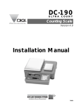
2.0 Installation ......................................................................................................................................... 8
2.1 Unpacking .......................................................................................................................................... 8
2.2 Repacking .......................................................................................................................................... 9
2.3 Setting Up .......................................................................................................................................... 9
2.4 Powering Up the DC-200/300 ............................................................................................................ 9
2.5 Initialize Scale Specifications ............................................................................................................. 10
2.6 Start-Up Screens .............................................................................................................................. 11
2.7 Calibration (Span Adjustment) ........................................................................................................... 12
2.8 Setting Time and Date ...................................................................................................................... 15
2.9 Configuration Settings ....................................................................................................................... 15
2.9.1 Configuring Specification 141 and 142 Settings from the Scale Keyboard ................................................ 15
2.9.2 Configuring Spec 141 and 142 Settings Using the Spec Upload Utility ..................................................... 27
2.10 Modes of Operation ........................................................................................................................ 36
3.0 Maintenance ....................................................................................................................................37
3.1 Hardware Testing ............................................................................................................................. 37
3.1.1 RAM and Communications Port Testing ................................................................................................... 37
3.1.2 Internal Test Count ................................................................................................................................... 41
3.1.3 Span Switch Status Test........................................................................................................................... 41
3.1.4 Voltage Checkpoints ................................................................................................................................. 41
3.2 Internal Printer Tests and Adjustments (DC-300 only)........................................................................ 42
3.2.1 Checking or Rezeroing the Thermal Head Usage Counter ........................................................................ 42
3.2.2 Adjusting the Printer Label Gap Sensor ..................................................................................................... 43
3.2.3 Adjusting the Printing Position................................................................................................................... 45
3.3 Clearing the Scale Memory ............................................................................................................... 45
3.4 Technical Drawings ........................................................................................................................... 47
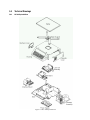
3.4.1 DC-300 Exploded View ............................................................................................................................ 47
3.4.2 DC-300 Block Diagram ............................................................................................................................. 48
3.4.3 DC-200 Block Diagram ............................................................................................................................. 49
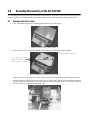
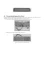
4.0 Assembly/Disassembly of the DC-200/300...................................................................................... 50
4.1 Removing the Main Cover ................................................................................................................. 50
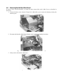
4.2 Disconnecting the Display Board ...................................................................................................... 51
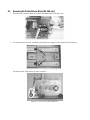
4.3 Disconnecting the Keyboard Circuit Board........................................................................................ 52
4.4 Removing the Interface Main Board .................................................................................................. 53
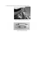
4.5 Removing the Printer Drawer Block (DC-300 only) ............................................................................ 54
4.6 Removing the Thermal Print Head (DC-300 only) .............................................................................. 55
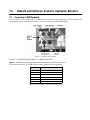
5.0 Network and Interfaces: External Printers ......................................................................................57
5.1 Connecting an External Printer to the Scale ....................................................................................... 57
5.1.1 Spec Settings for External Printers............................................................................................................ 57
5.1.2 Connecting the Printer to the RS-232C Port ............................................................................................. 58
5.2 Eltron Printers ................................................................................................................................... 59
5.2.1 Set the Computer Serial Port .................................................................................................................... 59
5.2.2 Designing a Label ..................................................................................................................................... 60
5.2.3 Saving the Label Format You Have Made ................................................................................................. 64
5.2.4 Downloading the Label Format From the Computer to the Eltron Printer .................................................. 67
5.2.5 Predesigned Label Formats for Eltron Printers .......................................................................................... 68
5.2.6 Testing to See What Label Format or Graphic is in the Eltron Printer’s Memory ........................................ 73
5.2.7 Printing to the Eltron Printer from the DC-200/300 Scale.......................................................................... 75
5.3 Epson Printers ................................................................................................................................... 76
6.0 Network and Interfaces: Connection to a PC ..................................................................................77
6.1 Ethernet Connection ......................................................................................................................... 77
6.1.1 Checking the Scale’s IP Address.............................................................................................................. 77
6.1.2 Machine Setup Utility................................................................................................................................ 77
6.1.3 Changing the IP Address Directly on the Scale ......................................................................................... 78
6.1.4 Ethernet Cable Connection Between the Scale and the Computer ........................................................... 79
6.1.5 Setting the Computer’s Network Communication ..................................................................................... 79
6.1.6 Entering the Data Transfer Mode on the Scale.......................................................................................... 81
6.1.7 Exiting The Data Transfer Mode on the Scale ........................................................................................... 82
6.1.8 Pinging the Scale to Test the Ethernet Connection ................................................................................... 83
6.2 RS-232 Connection .......................................................................................................................... 84
6.2.1 Spec Settings for RS-232C Connection to a PC ....................................................................................... 84
6.2.2 Connecting the PC to the RS-232C Port .................................................................................................. 85
6.2.3 Configuring Communication Between the Scale and the Computer .......................................................... 86
6.2.4 Setting HyperTerminal to Capture Data Coming From the Scale................................................................ 86
6.2.5 Sending Data from the Scale to HyperTerminal ........................................................................................ 87
6.2.6 Scale Data Header Codes ........................................................................................................................ 87
6.2.7 Requesting Data From the Scale Using HyperTerminal ............................................................................. 88
7.0 Network and Interfaces: Scanners, Keyboards, Balances.............................................................. 89
7.1 Connecting an IBM Keyboard ........................................................................................................... 89
7.2 Connecting a Barcode Scanner ........................................................................................................ 90
7.2.1 Header Codes.......................................................................................................................................... 90
7.2.2 Z Commands via Barcodes ...................................................................................................................... 91
7.2.3 Configuring the RS-232C Port for a Scanner ............................................................................................ 91
7.2.4 Connecting the Scanner to the RS-232C Port .......................................................................................... 92
7.2.5 Configuring the Keyboard Port for a Scanner ........................................................................................... 92
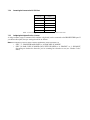
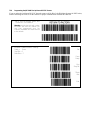
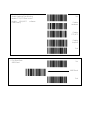
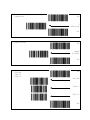
7.2.6 Programming the QSC-6000 Plus Quickscan RS-232C Scanner ............................................................. 93
7.2.7 Programming the QuickScan Keyboard Wedge Scanner.......................................................................... 98
7.3 Connecting a Force Balance ............................................................................................................. 99
7.3.1 Spec Settings for Force Balance .............................................................................................................. 99
7.3.2 Connecting the Force Balance to the RS-232C Port .............................................................................. 100
8.0 Firmware Upgrade .........................................................................................................................101
8.1 Determining Your Current Firmware Version Number ...................................................................... 101
8.2 Installing the WinDload Software ..................................................................................................... 101
8.3 Setting Up the WinDload Software .................................................................................................. 104
8.4 Connecting the DC-200/300 Scale to the Computer ....................................................................... 108
8.5 Downloading Firmware to the Scale ................................................................................................ 109
9.0 Appendix ........................................................................................................................................112
9.1 DC-200/300 Error Message List ...................................................................................................... 112
9.2 Appendix - Rezero Functions .......................................................................................................... 114
9.3 Character Code Tables ................................................................................................................... 116
9.3.1 ASCII Code ............................................................................................................................................ 116
9.3.2 Teraoka Codes ....................................................................................................................................... 118
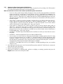
About This Manual
This manual contains technical instructions and procedures for servicing the DC-200/300 counting scale. It is for
the use of DIGI scale dealers and authorized technicians. The manual does not attempt to cover again all of the
operating procedures covered in the DC-200/300 operation manual nor does it cover every possible service
situation. If you have questions regarding this manual or a service-related situation not covered by this manual,
please contact the Service Department by calling 715-234-9171. This manual applies to Version 1.37 of the
DC-200/300 counting scale.
Caution
Some procedures described in this manual require work inside the scale base. These
procedures are to be performed by qualified service personnel only.
Authorized distributors and their employees can view or download this manual from the
DIGI distributor site at www.DigiScales.com.
1.0
1.1
Overview
DC-200/300 Specifications
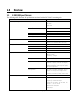
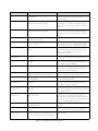
The following table illustrates all specifications associated with the DC-200/300 counting scale.
General Operating Specifications
Weight Display Resolution
1/2,500
1/5,000
1/10,000
Counting (internal) Resolution
1/1,000.000
Power Source and Frequency
AC 100-120V, 50/60 Hz
Battery (DC-200 only) 12V, 3.2 Ah/20hr
Power Consumption
Dimensions
Analog Specifications
Digital Specifications
Mechanical Specifications
50W
Operating Temperature
-10 C to 40 C (14 F to 104 F)
Operating Humidity
15 to 85% RH Maximum
Platter Size
360 x 275 mm / 14.17 x 10.83 in
Dimensions
410 mm (L) x 378 mm (W) x 140 mm(H)
16.14 in (L) x 14.88 in (W) x 5.52 in (H)
Load Cell Excitation
12 VDC
Number of Load Cells
four 350 ohm load cells maximum
Scale Channels
Up to 3 scales including the built-in scale
Input Sensitivity
0.4 - 2.0mV/V
Display
LCD with backlight (136 x 16 dots w/ icon)
Weight: 5 digits
Unit Weight: 5 digits
Quantity: 7 digits
Memory
2 Mb standard (up to 5000 items)
Programmable Data per Item
ID code (32 digits), Unit weight (5 digits), Part
number (32 digits), Part name (32 digits),
Location (32 digits), Inventory (8 digits),
Threshold (8 digits), Tare weight (5 digits),
Set point target data
Printing Items
ID code, Lot number, Net weight, Gross
weight, Unit weight, Tare weight, Parts
name, Parts number, Quantity, Task
contents, Barcodes (code 39, code 128)
Keyboard Keys
Mechanical switch
Number of Preset Keys
32 preset keys
Printer Type (DC-300 only)
Drawer type
Paper types: label and receipt
Paper width: for label - max. 60 mm, for
receipt - 40, 50, or 60 mm
Resolution: 8 dots/mm
Speed: For label - 80 mm/sec, for receipt 100 mm/sec
Table 1-1. DC-200/300 Specifications
Interfaces and Ports
Electronic Components
Amphenol
one 14-pin interface to scale
RS-232C
three RS-232C data ports (8-pin DIN) to PC,
printer, force balance or scanner
Ethernet
one Ethernet port to PC, hub, or router
IBM Keyboard
one IBM keyboard port
Main CPU
Hitachi HD6413003RF16 (H8/3003)
Flash Memory
MBM29F160BE-70
SRAM
Hyundai HY628400ALLG-55 (Normal pin)
Mitsubishi MEM5408ART-55LL (Reverse pin)
Display Device
IDW RD747SG-LG
Printing Head (DC-300)
Kyocera KYT-56-8MPP1-TRS
DC Stepping Motor (DC-300)
Minebea 17PM-K448-G5V
A/D Converter
Teraoka TWB-09130 (AD Main Board)
Power Supply (DC-300)
NEMIC Lambda ZD75-0524
Table 1-1. DC-200/300 Specifications
1.2
Keyboard and Display
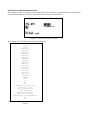
Figure 1-1 shows the DC-200/300 console with annunciators, the alphanumeric keyboard and the numeric
keypad. Annunciators are described in Section 1.2.1. Section 1.2.2 describes the DC-200/300 keyboard and
keypad.
Figure 1-1. DC-200/300 Display
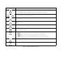
1.2.1
Annunicators
Table 1-2 shows a list of the annunciators that the DC-200/300 uses to provide additional information about the
value being displayed. The annunciators are illuminated when the specific function is being performed.
Annunciator
Annunciator Meaning
→0←
Gross weight is zero
NET
Display shows net weight (when tare weight is entered or recalled)
RECOM
Unit weight is recomputing is possible
INSUFF
Net weight is below specified percentage of scale capacity
∑
Memory indicator showing quantity accumulation is being done
IN
Inventory IN (for counting mode)
OUT
Inventory OUT (for counting mode)
PE
Paper end.
R
Scale is in Registration Mode, also referred to as Operation Mode. (see Section 2.10 for description
of modes)
S
Scale is in Programming Mode. (see Section 2.10 for description of modes)
X
Scale is in Report Mode. (see Section 2.10 for description of modes)
Z
Scale is in Service Mode. (see Section 2.10 for description of modes)
Table 1-2. DC-200/300 Annunciators and Function
1.2.2
Key Functions
The DC-200/300 features a full alphanumeric keyboard with many functions for managing inventory information
and scale operation. Table 1-3 lists the keys and key functions of the DC-200/300 keyboard and keypad (see
Figure 1-1 on the previous page).
Note: Some keys have different functions depending on what mode you are in, so be sure to check which mode is
selected before using them.
.
Description
Key
Turns the scale display on or off
to
Used to enter numeric values. When using the scale, first enter a numeric value, then press the
appropriate function key.
Allows cycling between the different modes:
• Operation Mode – weighing and counting operations
• Report Mode – print item, inventory, and shelf location reports
• Program Mode – entering item data, factory name
• Password Mode – password protecting certain operations
• Service Mode -setup and troubleshooting by an authorized dealer or technician
• Operation Mode – set and clear tare weights
• Program Mode – do an item test print
• Other Modes – used to select “No”
• Operation Mode – clear keyed-in data from the display starting with the last digit entered
• Other Modes – used to select “Yes”
Used to reset the scale to zero. Also used in conjunction with other keys to enter the maintenance
mode. The REZERO key does not function when the scale is in motion.
• Operation Mode - compute unit weight by sampling. Press the PIECES key after placing a
10-piece sample on the platform, or after using the numeric keypad to enter the sample size. On
multi-channel units, ensure that the correct scale is selected.
• Other Modes - escape the programming screen without saving data
Used to enter a known unit weight using the numeric keypad
• Operation Mode – accumulate the total quantity
• Program Mode – select an item to be programmed such as item code, factory name, or cycle
through set-point modes
• Report Mode – select the type of report to print
• SPEC Setting – move between SPEC numbers (low to high)
•
•
•
•
Program Mode –- select programming item such as item code, factory name
Report Mode – select report type
Other Modes – enter the delete function
SPEC Setting – move between SPEC numbers (high to low)
• Operation Mode – call up stored item code information and switch between item code inventory
IN and OUT modes
• Program Mode – store the programmed data
Enter numeric values containing a decimal point
Note: A numeric value must be entered before the decimal point. For example, .250 would be
entered as 0.250.
Feed label or receipt paper (DC-300 only)
Cycle between Scales A through D when using the DC-200/300 as a multi-scale system.
Table 1-3. DC-200/300 Key Functions
Key
Description
• Operation Mode – print a label or report
• Report Mode – print out a report
• Program Mode – enter information about an item into temporary memory
to
• Operation Mode – view item code data stored in memory
• Program Mode – enter alphabetic data
Move the cursor. Change the entry to the right. Also used to cycle forward between choices in SPEC
setting mode.
Move the cursor. Change the entry to the left. Also used to cycle backward between choices in
SPEC setting mode.
Select the top function or character of a desired character key
Select the bottom function or character of a desired character key, generally to quickly view the
values in different registers
Shift between code type for keyboard entry. Options are:
• P:KEY - enter the letter or number corresponding to the key pressed
• A:KEY ASCII code - select by entering the hex code for the character
• T:KEY Teraoka code - select by entering the numeric value for the character
Section 9.3 on page 116 - Character Code Tables
Delete data
Insert data
Table 1-3. DC-200/300 Key Functions
1.3
Interface Ports
The DC-200/300 is equipped with a number of interface ports enabling it to be connected with other devices.
There are RS-232C ports that allow connection to bar code readers, printers or force balances. An IBM keyboard
interface permits connection to an external keyboard or wedge scanner. The Ethernet connection makes the
DC-200/300 a networkable workstation and allows you to use the Utility Transfer and Label Design programs.
Figure 1-2. DC-200/300 Interface Ports
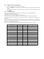
1.4
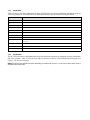
Capacities and Resolutions
Table 1-4 lists the scale capacities and resolutions for all models of the DC-200/300 counting scales. The system
weighing accuracy is 0.02 percent.
Counting scales specify two types of resolution:
• Weight (or external) resolution
• Counting (or internal) resolution
Weight resolution is displayed in divisions of the full scale capacity which is divided into weight increments. For
example, a 5-lb scale divided into 10,000 display divisions would display weight with 0.0005 lb divisions
(10,000 divisions x 0.0005 lb = 5.0 lb).
Counting resolution is based on the internal resolution of the scale. The weight and counting resolutions for the
DC-200/300 capacities are shown below and apply to all models of DC-300 counting scales.
DC-200/300 Single Scale
Note: Units are selectable from lb to kg and can be programmed to weigh in other primary units: lb, kg, g.
Capacity
Mounting Internal/External
Weight Resolution
Counting Resolution
Platform Dimension
1.0 lb
Both
0.0001
0.000001
6" x 8"
2.5 lb
Both
0.0002
0.000002
7" x 10"
5.0 lb
Both
0.0005
0.000005
12" x 14"
10.0 lb
Both
0.001
0.00001
12" x 14"
25.0 lb
Both
0.002
0.00002
12" x 14"
50.0 lb
Both
0.005
0.00005
12" x 14"
Table 1-4. DC-200/300 Single Scale Capacities
The external scale platform connector allows the DC-200/300 to connect with another larger capacity platform. A
third scale can be added by using the optional Y cable to connect to the external scale connector. with the ability
to add a force balance, barcode scanner, external printer and/or keyboard, your DC-200/300 becomes the hub of
a sophisticated weighing system with huge capacities for expandability and flexibility.
2.0
Installation
This section describes the procedure for the installation and setup of the DC-200/300 counting scale.
2.1
Unpacking
Caution
Do not turn scale upside down. Always work with scale on its side! Damage to the load cell
can occur if the scale is turned upside down.
Immediately after unpacking, visually inspect the DC-200/300 counting scale to ensure all components are
included and undamaged. If any were damaged in shipment, notify Rice Lake Weighing Systems and the shipper
immediately.
The DC-200/300 counting scale is packed in custom-fitted foam. After opening the box, remove all the
components. Check the insides of the box carefully to make sure you have all of the pieces. The package should
include the following:
• DC-200/300 counting scale
• Stainless steel platter
• AC power cord
• DC200/DC300 set-up tools CD-ROM
• Thermal head cleaning kit (DC-300 only)
• Thermal printer take-up reel (DC-300 only)
• DIGI certificate of quality
• Spare keysheet label
Figure 2-1. DC-200/300 Unpacked
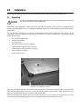
Remove the bag protecting the scale and the dessicant bag. Next remove the protective film covering the front
panel and the foam spacers between the scale case and the platform spider. Finally, place the stainless steel
platter on top of the scale and seat it securely on the rubber stops.
After insuring that all the parts are present, store the original box in a safe location for possible future use. You
will want the original packaging if you ever need to transport the scale or send it for servicing.
2.2
Repacking
If the DC-200/300 counting scale must be returned for modification, calibration or repair, it must be properly
packed with sufficient cushioning materials. Whenever possible, use the original carton when shipping the
DC-200/300. Damage caused by improper packaging is not covered by the warranty.
2.3
Setting Up
Place the scale on a solid, level surface away from fans, breezes, and sources of electrical interference.
Level the scale by turning the four adjustable legs located on the bottom of the scale while referencing the bubble
level located on the front of the scale (see Figure 2-2).
Note:To ensure a higher degree of scale stability, turn in all four adjustable legs before leveling. Turn out adjustable
legs to level as needed.
Figure 2-2. Leveling Feet and Bubble
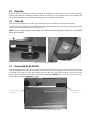
2.4
Powering Up the DC-200/300
After plugging the power cord into the socket on the bottom of the scale (Figure 2-3) turn the power switch on
the back of the bottom of the scale to the ON position. Generally when starting up the scale, if the power switch
is currently OFF, turning it to the ON position powers up the scale. If the power switch is already in the ON
position but the display has been powered down by pressing the ON/OFF key on the front, the scale can be
reactivated by pressing the ON/OFF key again.
Power cord
location
Power switch
location
Figure 2-3. Power Switch and Power Cord Location
2.5
Initialize Scale Specifications
When first setting up the DC-200/300 scale, the specifications can all be set to their default values in one
procedure. The scale has three possible sets of default values: Japan, U.S.A., and Standard. If the scale will be
used in the United States, the best initial combination of settings will be the U.S.A. Remember that you can
customize many functions of the scale to fit your customer’s application by modifying these specification
settings. For more information on the default settings of each specification and their optional settings, see Section
3.0 of the DC-200/300 Operation Manual.
Note: This procedure clears the scale’s SDRAM before initializing the specification settings to their default values.
This means that all item code information, customized specification settings and custom free label formats will be
erased by performing this procedure.
1. Turn on the Span Switch and then power on the scale.
2. Press and hold and REZERO key while entering 124 from the numeric keypad to enter the Select
Country Spec mode.
3. Use the << or >> key to scroll through the Country code options. (The options are 0-AA (Japan), 1- US
(USA), and 3-STD (Standard). When the display shows 1-US, press the REPRINT key to select it.
4. The scale will next move to the Select Scale Type mode. Use the << or >> keys to select either 0 DC300
or 1 DC200.
Press the REPRINT key to confirm your selection.
5. The scale will indicate that it is reading the default country specs for the country setting you selected in
Step 2 above.
6. The scale will next ask you if you want to clear all the SDRAM memory in the scale and intialize all the
files and specifications. Press the CLEAR key to clear the memory and intialize the specifications or the
TARE key to exit without reinitializing.
Caution
Pressing the Clear key will also erase any item code files, inventory records, and custom label
formats you have programmed into the scale previously.
If you press the CLEAR key to reinitialize, the scale will display a message saying PLEASE WAIT..., while
the procedure is taking place.
7. Once the settings are reinitialized, the scale will go through its normal start-up segment check and then
return to the Span Switch On Mode.
2.6
Start-Up Screens
The instructions below assume that you are using the scale as a stand-alone unit, with or without remote
platforms. For information on using the DC-200/300 as a network workstation, see Section 6.0.
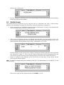
1. As the scale powers up it will display the current version of the firmware it is using. It also shows that the
scale is currently being operated as a stand-alone unit.
2. After a test of the different elements of the display, the scale takes you to the stand-by screen in the
Operation Mode. At the stand-by screen the WEIGHT, UNIT WEIGHT and QUANTITY displays show zeroes
and the annuciator for the platform you are using is illuminated (A, B, C or D).
From this stand-by screen all of the basic weighing, counting and inventory operations can be performed
(See Section 6.0 on page 77). Also, if any job sequence instructions have been programmed into the
scale, the first operator instruction will be displayed on the second line of the display (Section 8.0).
3. If there is anything on the platform(s) and it exceeds the scale start range, a beep sounds, and the
following error message appears.
Note: The Initial Start Range settings are controlled by SPEC 631. The default setting is 0: +UNLIMITED TO 10%
OF FULL SCALE.
Remove the weight from the platform and press the CLEAR key to exit.
2.7
Calibration (Span Adjustment)
The DC-200/300 counting scale is a high-precision instrument. Although the scale needs very little maintenance,
you may want to check the calibration after every month or so of normal usage. To do this you will need to have
a test weight of approximately the total capacity of the scale (i.e. a 10 lb weight if you have a 10 lb capacity
scale). After the scale is initially installed, put the weight on the platform and record the weight displayed. Then
every month or so put the same weight on the scale and verify that it still reads the same.
Many facilities have a technician come in and check their units with certified test weights four times a year. If
you are ISO certified, you will want to check to see if your certification specifies more stringent requirements to
stay in compliance. Your DIGI scale dealer has the calibrated test weights, expertise and experience to perform
this task for you as well as to check other operating parameters of your scale and help you effectively integrate
scales into your operations. If you do not know who your local DIGI dealer is, call us at 1-715-736-0002 and we
will help you find someone who can provide you with on-site support.
Follow the instructions below to calibrate your DC-200/300 scale to ensure its continued accuracy.
1. Make sure the scale is turned off. Then press the span switch to reset it. See Figure 2-4 for location of
Span switch).
Figure 2-4. Location of Span Switch
2. Turn the scale back on. the scale displays the message, CHANGE SPAN SWITCH.
3. While pressing the REZERO key, enter 8715 from the numeric keypad to enter the calibration mode.
4. The scale display confirms that you are in the Calibration Mode.
5. Next, press the REPRINT key to enter the zero setting mode.
6. Choose which scale platform you are calibrating. The scale defaults to platform A. To choose another
scale platform, press the SCALE key until the platform you want to calibrate is displayed.
7. Make sure that nothing is on the scale platform and press the CODE key to have the scale automatically
search for the zero point.
8. The scale displays the zero point in the quantity window. It should be a value between 9000 and 11000.
If the scale does not catch that range, you will need to call your local DIGI dealer or call us at
1-715-736-0002 for service assistance.
9. Press the REZERO key to clear the Internal Count shown in the weight window.
10. Press the REPRINT key to enter the weight calibration setting.
11. Put a calibrated weight on the platform equal to the total capacity of the scale (Example, for a 25 lb scale,
place a 25 lb weight on the scale). Alternatively, you can enter the weight from the numeric keypad. The
weight appears in quantity window. Press the REPRINT key to save the calibration data.
The display confirms that the span settings for calibration of the scale are being saved
Finally the screen returns to the initial CHANGE SPAN SWITCH.
12. Once the span switch is turned off, the scale automatically returns to operation mode. The scale should
now be powered off and restarted for the new settings to take effect.
2.8
Setting Time and Date
Once you set the internal clock for the correct day and time it will continue to keep them, even when the scale is
off, using the internal battery on the main board. The procedure below can also be used to adjust the time when
moving from Standard to Daylight Savings Time or when the scale is moved to a new facility in a different time
zone.
Note: SPEC 05 - DATE ORDER and SPEC 06 -TIME FORMAT allow you to set the format for date and time that
you prefer the scale to display. The defaults are Month/Date/Year for date and 12 hour for time. To change these
specifications, see Section 2.9.1.
1. Press the MODE key twice until the display shows ITEM CODE PROGRAMMING. The S annunciator,
indicating the Programming Mode, will illuminate.
2. Press the + (plus) or – (minus) keys to scroll through the programming options until you see the
PROGRAM DATE screen. Enter the current date using the numeric keypad. For months or days from 1 to
9, enter a leading zero. (Ex. In a MM-DD-YY format, May 8, 2003 would be entered as 050803.) Press
the REPRINT key to store the data in temporary memory and move to the time programming mode.
3. Enter the current time using the numeric keypad. For numbers from 1 to 9, enter a leading zero. (Ex. In a
12 hour format, 3:06 pm would be entered as 0306.) If SPEC 06 - TIME FORMAT is set to a 12 hour
format, you use the << and >> keys to toggle between AM and PM.
4. Press the CODE key to save the data or press the PIECES key followed by the CLEAR key to exit without
saving the data.
5. To return to the Stand-by Screen in the Operation Mode, press the MODE key three times.
2.9
Configuration Settings
This section presents the setup and configuration of the DC-200/300 counting scale to be used specifically by
distributors and service technicians. Configuring these specifications allow you to tailor the DC-200/300 to your
specific applications.
Setting the specifications allows you to modify the functionality of the DC-200/300. Use the tables in this section
to view the options you can modify. For example, if you want the function allowing you to print labels by
pressing the +/- keys as well as pressing the REPRINT key to work on the DC-200/300, refer to the DC-200/300
specification table and locate SPEC 34 - PRINT WHEN PRESS +/- KEY. The default for SPEC 34 is 0, which
means that the PRINT WHEN PRESS +/- KEY function is turned off or disabled. To turn it on or enable it, change
the SPEC setting to 1.
2.9.1
Configuring Specification 141 and 142 Settings from the Scale Keyboard
The following tables list the DC-200/300 specifications and their corresponding default values. The default
values are automatically set when the scale’s memory is set by the dealer for the country of operation.
SPEC 00 through SPEC 71 (Table 2-1) are customer specifications and use the 141 access code, while SPEC 600
through SPEC 646 (Table 2-2) are weight and measurement specifications, and use the 142 access code. In
programming specifications, the REPRINT and – (minus) keys allow you to move to the next or previous
specification without saving changes to the SPEC code you were just in.
Customer Specification (141 Settings)
1. To configure customer specifications, press and hold the REZERO key and enter 141 using the numeric
keypad. The first SPEC code, SPEC 0 is displayed, with SP0: AUTO POWER SAVING appearing in the
first line of the weight display and its current setting (ex. 00>0: Disable) appearing in the second line.
If this is the SPEC that you want to modify, press >> or << keys to scroll through the possible settings.
When the setting you want to store is displayed, press the + (plus) key to enter the change into temporary
memory and move to the next SPEC code.
2. If you want to modify a SPEC other than SPEC 00 and you know the number of that SPEC code, enter
the number of the SPEC code on the numeric keypad and press the REPRINT key. Otherwise, you can
use the + (plus) and – (minus) keys to scroll through the specifications until you find the one you want.
Then make your changes per the instructions in Step 1.
3. To change another SPEC code before exiting, repeat Steps 1 and 2.
4. To save all the changed SPEC settings currently in temporary memory and exit to the Operation Mode,
press the CODE key. You will hear a long beep to confirm that the scale is saving the change. The saving
of the configuration file takes about 10 seconds, after which the scale will return to the Stand-By mode.
To exit to the Operation Mode without saving the changes, press the TARE key.
Caution
If you power off the scale while the saving process is going on, you can clear the entire
memory of the scale. Wait until the scale has returned to the Stand-by screen before
performing any other functions.
5. Power down scale using the power switch on the back of the bottom of the scale, not the ON/OFF key on
the keyboard.
6. Power scale on to re-initialize the new specification settings.
SPEC
Description
00
Auto Power Saving When No Weight Change & No Key Press
0: Disable (DEFAULT)
1: 1 minute
2: 2 minutes
3: 3 minutes
4: 4 minutes
5: 5 minutes
6: 6 minutes
7: 7 minutes
8: 8 minutes
9: 9 minutes
10: 10 minutes
11: 11 minutes
12: 12 minutes
13: 13 minutes
14: 14 minutes
15: 15 minutes
01
Power Saving Type
When set to 0, the backlight turns off when the scale goes into power-saving mode. When set to 1,
the scale turns off entirely
0: Backlight Off (DEFAULT)
1: Power Off
02
Negative Counting
0: No
1: Yes (DEFAULT)
03
Extent of Insufficient Samples
Sets the percentage of the full scale capacity that the initial counting sample has to exceed, otherwise
the INSUFF lamp lights.
0: 0.1% (DEFAULT)
1: 0.2%
2: 0.0%
04
Set New Item Code During Registration (Operation) Mode
0: Yes (DEFAULT)
1: No
05
Date Order
0: Month/Day/Year (DEFAULT)
1: Day/Month/Year
2: Year/Month/Day
06
Time Format
0: 24 hour (DEFAULT)
1: 12 HOUR (am/pm)
07
Unit Weight Auto Recomputing
0: No (DEFAULT)
1: Yes
08
Sampling Times for Unit Weight Calculation
Higher number samples improve accuracy in environments of higher vibration or breeze but also
increase the time required to compute the unit weight.
0: 15 times (DEFAULT)
1: 20 times
09
Display Accuracy Unit Weight Calculation During Recomputing
0: No (DEFAULT)
1: Yes
SPEC
Description
10
Set Point Buzzer
0: Buzzer on (DEFAULT)
1: Buzzer off
11
Clear All Input Key in One Touch
0: Yes
1: No (DEFAULT)
12
Keep Lot Number in Registration (Operation) Mode
0: Allow (DEFAULT)
1: Inhibit
13
Job Sequence
0: Disable (DEFAULT)
1: Enable
14
Auto Exit From Add Mode
0: No
1: Yes (DEFAULT)
15
SIO Select Job
Defines what the primary or standard input/output port on the scale is connecting to.
0: No operation (DEFAULT)
1: Force Balance
2: PC
3: Printer
4: Bar Code Scanner
16
RS-232C Baud Rate (SIO - Standard Input/Output Port)
0: 1200 baud
1: 2400 baud
2: 4800 baud
3: 9600 baud (DEFAULT)
4: 19200 baud
5: 38400 baud
17
RS-232C Data Length (SIO - Standard Input/Output Port)
0: 7 bits
1: 8 bits (DEFAULT)
18
RS-232C Parity Bit (SIO - Standard Input/Output Port)
0: None (DEFAULT)
1: Odd
2: Even
19
RS-232C Stop Bit (SIO - Standard Input/Output Port)
0: 1 bit (DEFAULT)
1: 2 bits
20
RS-232 Option Card
0: Not connected (DEFAULT)
1: Printer/Force balance
2: Force balance/Printer
3: Printer/PC
4: PC/Printer
5: PC/Force balance
6: Force balance/PC
21
RS-232 Baud Rate for 8 Pin DIN 1 Connector
0: 4800
1: 9600 (DEFAULT)
2: 19200
3: 38400
SPEC
Description
22
RS-232 Data Length for 8 Pin DIN 1 Connector
0: 7 bits
1: 8 bits (DEFAULT)
23
RS-232 Stop Bit for 8 Pin DIN 1 Connector
0: 1 bit (DEFAULT)
1: 2 bits
24
RS-232 Parity Bit for 8 Pin DIN 1 Connector
0: None (DEFAULT)
1: Odd
2: Even
25
RS-232 Baud Rate for 8 Pin DIN 2 Connector
0: 4800
1: 9600 (DEFAULT)
2: 19200
3: 38400
26
RS-232 Data Length for 8 Pin DIN 2 Connector
0: 7 bits
1: 8 bits (DEFAULT)
27
RS-232 Stop Bit for 8 Pin DIN 2 Connector
0: 1 bit (DEFAULT)
1: 2 bits
28
RS-232 Parity Bit for 8 Pin DIN 2 Connector
0: None (DEFAULT)
1: Odd
2: Even
29
RS-232 Connection to Force Balance (FB)
0: Disable (DEFAULT)
1: Enable
30
Type of Force Balance
0: Export (DEFAULT) 2:S-HG200
1: HR-603:S-HG300
31
PC/PRN Output Data Method
0: No operation
1: Counting
2: By +/-/Print Key (PC/PRN) (DEFAULT)
3: For both classes 1 & 2
32
Select External Printer Type
0: Eltron LP2622/LP2722 or TVP1000 (DEFAULT)
1: SE520
2: DP122 (Japan)
3: Epson output
33
External Eltron/TVP Printer Download Label Format
0: Enable (DEFAULT)
1: Disable
34
Print When Press +/- Key
0: Disable (DEFAULT)
1: Enable
35
PC Data With Header
0: Yes (DEFAULT)
1: No
36
PC Data Header Type
0: Code 9 - numeric headers (DEFAULT)
1: Title - alphabetic headers
SPEC
Description
37
IBM Keyboard Port
0: IBM Keyboard
1: Scanner
38
Barcode Scanner (BCS) With Header
0: Yes (DEFAULT)
1: No
39
Track Nprint (TNP) Time Out
0: 2 seconds (DEFAULT)
1: 8 seconds
2: 32 seconds
40
Selection of Network Interface
0: No network (RS-232) (DEFAULT)
1: Twisted Cable (Ethernet)
41
Port Number (IP Address)
The port number can be set anywhere in a range from 1 to 255 (DEFAULT = 001 for DC-300)
(DEFAULT = 002 for DC-200)
42
Set Scale Number
The scale number can be set anywhere in a range from 0 to 999999 (DEFAULT = 00001)
43
Select Receipt or Label Paper Printing
0: Print paper receipt
1: Print label paper (DEFAULT)
44
Printing Speed For Receipt
0: Slow
1: Normal (DEFAULT)
2: High
45
Printing Speed for Label
0: Slow
1: Normal (DEFAULT)
2: High
46
Label Printing Density
0: Low
1: Medium
2: Medium High (DEFAULT)
3: High
47
Label Type
0: Gap (DEFAULT)
1: No Gap
48
Peel Sensor Function
The peel sensor determines whether labels are set to be printed with the backing left on (0: disable) or
with the backing peeled part way so that an individual label can be removed easily from the backing
for immediate use (1: enable).
0: Disable
1: Enable (DEFAULT)
49
Number of Reprint Labels
0: No Label
1:1 Label (DEFAULT)
2:2 Labels
50
Selection of Label and Receipt Printing Operation
0: All operation (in/out/non-add) (DEFAULT)
1: Out (shipping operations)
2: In (receiving operations)
3: In and out
4: No printing
SPEC
Description
51
Human Readable Barcode Printing Format
0: No print (DEFAULT)
1: Print
52
Item Data Printing Format (DC-300 only)
Sets the justification for printing the data associated with item codes in memory such as ID codes,
part name, part number, and lot number
0: Centering
1: Start printing from the left (DEFAULT)
53
Date Title Print (DC-300 only)
0: No
1: Yes (DEFAULT)
54
Weight Data and Quantity Title Print (DC-300 only)
0: No print
1: Print (DEFAULT)
55
Printing of Factory Name on Label (DC-300 only)
0: No print
1: Print (DEFAULT)
56
Default Printing Label Factory Number (DC-300 only)
Can choose a factory number in a range from 0 to 32. (DEFAULT = 01)
57
Printing of Factory Name Format (DC-300 only)
0: No centering
1: Centering (DEFAULT)
58
Selection of Label Logo Printing Status (DC-300 only)
0: No print (DEFAULT)
1: Logo 1
2: Logo 2
3: Logo 3
4: Logo 4
59
Selection of Barcode Type
0: Code 128A
1: Code 128B
2: EAN 128A
3: EAN 128B
4: CODE 39 (DEFAULT)
60
Auto Print Function
0: Between set point 1 and set point 2
1: Disable (DEFAULT)
61
Ethernet Function
0: No operation
1: Track N Print
2: Data Transfer Mode
62
RS232 - XON/XOFF
0: Disable
1: Enable
63
Sample Quantity
Determines the number of pieces the scale assumes are on the platter when you press the PIECES
key to calculate the Unit Weight.
0: 10 pieces (DEFAULT)
1: 25 pieces
2: 50 pieces
3: 100 pieces
SPEC
Description
64
Scale A <–> B
Sets whether the unit weight determined by sampling on Scale A is automatically transferred to Scale
B or not.
0: Manual (DEFAULT)
1: Auto
65
Unit of Pcs Weight
Sets whether the unit weights are displayed per 1000 pieces or per 1 piece. For a further discussion of
the benefits of each option, please see Section 5.4.
0: 1000 pieces (DEFAULT)
1: 1 piece
66
Not used
67
IMS
Determines whether or not the scale automatically queries the DIGI Inventory Management Software
(IMS) for all of the parameters associated with an Item Code when the CODE key is pressed. For
more information on this option, please see Section 6.3.1.
0: Disable (DEFAULT)
1: Enable
68
EPSON II
Changes the Epson label format from the default (all item information fields) to an abbreviated format
with only selected fields.
0: Disable (DEFAULT)
1: Enable
69
4 Lot No.
If disabled, allows a single lot number to be entered during weighing operations. If enabled, allows up
to 4 lot numbers to be entered. These lot numbers are not written to the item database.
0: Disable (DEFAULT)
1: Enable
70
Upload Lot and Part Number
If disabled, lot numbers and part numbers entered during weighing operations are not uploaded to the
item database. If enabled, lot numbers and part numbers entered during weighing operations
overwrite the information previously stored with the item code in the scale memory.
0: Disable (DEFAULT)
1: Enable
71
Text 11-16 TTL
Allows you to use text fields 11-16 on total labels rather than just item labels.
0: Disable (DEFAULT)
1: Enable
Table 2-1. DC-200/300 (141) Settings
Weight and Measurement Specification (142 Settings)
1. Press and hold the REZERO key and enter 142 using the numeric keypad. SP600 appears in weight
display and its current setting (ex. 2>2: LB) appearing in the second line. If this is the SPEC that you
want to modify, press the >> or << keys to scroll through the possible settings. When the setting you
want to store is displayed, press the + (plus) key to enter the change into temporary memory and move to
the next SPEC code.
2. If you want to modify a SPEC other than SPEC 600 and you know the number of that SPEC code, enter
the number of the SPEC code on the numeric keypad and press the REPRINT key. Otherwise, you can
use the + (plus) and – (minus) keys to scroll through the specifications until you find the one you want.
Then make your changes per the instructions in Step 1.
3. To change another SPEC code before exiting, repeat Steps 1 and 2.
4. To save all the changed SPEC settings currently in temporary memory and exit to the Operation Mode,
press the CODE key. To exit to the Operation Mode without saving the changes, press the TARE key.
5. Power down scale using the power switch on the back of the bottom of the scale, not the ON/OFF key on
the keyboard.
Power scale on to re-initialize the new specification settings.
Spec
Description
600
Scale Unit Specification
0: Gram
1: Kg
2: Lb (DEFAULT)
601
Display Resolution
0: 1/10000 (DEFAULT)
1: 1/5000
2: 1/2500)
602
Internal Count
0: 500,000
1: 1,000,000 (DEFAULT)
603
Minimum Display (Increment) for Scale A
0: 2 (DEFAULT)
1: 1
2: 5
3: 10
604
Weight Decimal Point Position for Scale A
0: 0
1: 0.0
2: 0.00
3: 0.000 (DEFAULT)
4: 0.0000
Spec
Description
605
Load Cell Sensitivity Selection in mV/V for Scale A
0: 4.00 mV/V
1: 3.76 mV/V
2: 3.52 mV/V
3: 3.28 mV/V
4: 3.04 mV/V
5: 2.80 mV/V
6: 2.56 mV/V
7: 2.32 mV/V
8: 2.08 mV/V
9: 1.84 mV/V
10: 1.60 mV/V
11: 1.36 mV/V
12: 1.12 mV/V (DEFAULT)
13: 0.88 mV/V
14: 0.64 mV/V
15: 0.40 mV/V
606
Load Cell Type for Scale A
0: Standard / Normal load cell (DEFAULT)
1: Abnormal load cell with large offset
607
A/D Board Type for Scale A
0: Normal (DEFAULT)
1: Prevent from small vibration / fast change in display
2: Prevent from medium vibration
3: Prevent from large vibration / slow change in display
608
External Scale B Connection
0: Disable (DEFAULT)
1: Enable
609
Minimum Display (Increment) for Scale B
0: 2 (DEFAULT)
1: 1
2: 5
3: 10
610
Weight Decimal Point Position for Scale B
0: 0
1: 0.0
2: 0.00
3: 0.000
4: 0.0000 (DEFAULT)
611
Load Cell Sensitivity Selection in mV/V for Scale B
0: 4.00 mV/V
1: 3.76 mV/V
2: 3.52 mV/V
3: 3.28 mV/V
4: 3.04 mV/V
5: 2.80 mV/V
6: 2.56 mV/V
7: 2.32 mV/V
8: 2.08 mV/V
9: 1.84 mV/V
10: 1.60 mV/V
11: 1.36 mV/V
12: 1.12 mV/V (DEFAULT)
13: 0.88 mV/V
14: 0.64 mV/V
15: 0.40 mV/V
Spec
Description
612
Load Cell Type for Scale B
0: Standard / Normal load cell (DEFAULT)
1: Abnormal load cell with large offset
613
A/D Board Type for Scale B
0: Normal (DEFAULT)
1: Prevent from small vibration / fast change in display
2: Prevent from medium vibration
3: Prevent from large vibration / slow change in display
614
External Scale C Connection
0: Disable (DEFAULT)
1: Enable
615
Minimum Display Increment for Scale C
0: 2
1: 1 (DEFAULT)
2: 5
3: 10
616
Weight Decimal Point Position for Scale C
0: 0 (DEFAULT)
1: 0.0
2: 0.00
3: 0.000
4: 0.0000
617
Load Cell Sensitivity Selection in mV/V for Scale C
0: 4.00 mV/V
1: 3.76 mV/V
2: 3.52 mV/V
3: 3.28 mV/V
4: 3.04 mV/V
5: 2.80 mV/V
6: 2.56 mV/V
7: 2.32 mV/V
8: 2.08 mV/V
9: 1.84 mV/V (DEFAULT)
10: 1.60 mV/V
11: 1.36 mV/V
12: 1.12 mV/V
13: 0.88 mV/V
14: 0.64 mV/V
15: 0.40 mV/V
618
Load Cell Type for Scale C
0: Standard / Normal load cell (DEFAULT)
1: Abnormal load cell with large offset
619
A/D Board Type for Scale C
0: Normal (DEFAULT)
1: Prevent from small vibration / fast change in display
2: Prevent from medium vibration
3: Prevent from large vibration / slow change in display
620
Tare Range Settings
0: 100% full scale (DEFAULT)
1: <50% full scale
2: <5% full scale
621
Digital Tare Setting
0: Disable
1: Enable (DEFAULT)
Spec
Description
622
Tare Accumulation
0: No (DEFAULT)
1: Yes
623
Digital Tare When Loaded
0: Allow (DEFAULT)
1: Inhibit
624
Tare Subtraction (for Load Tare Only)
0: Yes (DEFAULT)
1: No
625
Tare Addition (for Load Tare Only)
0: Yes
1: No (DEFAULT)
626
Tare Value Exchange (for Load Tare)
0: Yes (DEFAULT)
1: No
627
Zero Tracking When Tare
0: Yes (DEFAULT)
1: No
628
Tare When Scale Change
0: Old Tare (DEFAULT)
1: New Tare
629
Weight Reset When Tare
0: Yes (DEFAULT)
1: No
630
Auto Clear Tare When Rezero
0: No (DEFAULT)
1: Yes
631
Initial Start Range Settings
0: +Unlimited to 10% full scale (DEFAULT)
1: +/- 2% full scale
2: +/- 10% full scale
632
Zero Range Settings
0: +Unlimited to 10% full scale (DEFAULT)
1: +/- 2% full scale
2: +/- 10% full scale
633
Zero Lamp Lighting Method
0: Gross weight (DEFAULT)
1: Net weight
634
Rezero When Changing Scale
0: No rezero (DEFAULT)
1: Rezero
635
Stability Check When Changing Scale
0: Stability check (DEFAULT)
1: No stability check
636
Internal Count Resolution (IR) Protected by Span Switch
0: No (DEFAULT)
1: Span switch protect
637
Calibration/Default SPEC/SPEC 142 Mode Protected by Span Switch
0: Span switch protection
1: No protection (DELETE)
Spec
Description
638
Display at Minus Weight
0: Minus display (DEFAULT)
1: Masked display
639
Masked Display at Minus Weight
0: Gross weight (DEFAULT)
1: Net weight
640
Overweight Masked
0: At +1D (DEFAULT)
1: At + 9D
641
Selection of Scale Starting Method
0: Auto start (DEFAULT)
1: Manual start
642
Weight Unit Convert
0: Yes (DEFAULT)
1: No
643
Gross Mode Display
0: Yes (DEFAULT)
1: No
644
Selection of Decimal Point Type
Sets whether the decimal point is displayed as a period (U.S. usage) or a comma (European, Latin
American, Asian usage)
0: Period display (DEFAULT)
1: Comma display
645
Selection of Scale Type
0: DC-300 scale
1: DC-200 scale
646
Automatic Unit Weight Clear Conditions
0: Disable (DEFAULT)
1: Over net 5D & gross 21D & weight stable
2: >=net 1D & weight stable
3: >=net 1D & quantity > 0 & weight stable
Table 2-2. DC-200/300 (142) Settings
2.9.2
Configuring Spec 141 and 142 Settings Using the Spec Upload Utility
The DC-300 Utility Program includes a module called “Spec Upload”. This handy program allows you to more
easily do four useful things:
• change one or any number of spec settings from your computer screen and then upload them to a
DC-200/300 rather than change them from the scale’s keyboard.
• save the spec setting currently programmed in the DC-200/300 to a named file on your computer from
which they can be restored to the same DC-200/300 later or uploaded to other DC-200/300s so that their
spec settings match.
• save spec settings optimized for a particular task, department or facility to a named file on the computer.
This complete set of spec settings can then be uploaded to a DC-200/300 whenever the scale’s use or
location changes, rather than have to go through and manually change each spec. It can also be used to
save a backup of your spec settings if you should need to send your scale to be serviced.
Return all the scale’s spec settings to the default settings by uploading the defaults from the computer to the
scale.
Note: For information on how to install the DC-300 Utility Program on your computer, Section 8.2 on page 101 If
you have not already set up your computer and the scale to be able to communicate to each other using the
DC-200/300’s Ethernet connection, please see Section 6.1. If you are unsure of how to work with TCP/IP
connections or have difficulties, see your Network Administrator for help.
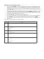
Change Spec Settings Using the Spec Upload Utility
1. With the scale turned on and at the Stand-by screen, press REZERO + SHIFT UP. The scale display will
indicate that it is changing to the data transfer mode.
2. The scale display will next indicate that it is ready for the data transfer mode after the scale is restarted.
Turn the scale off and then on again, using the on/off switch located on the bottom of the scale at the
back
3. After you restart the scale and it goes through its startup sequence, the scale will show that the data
transfer mode is ready.
4. On your computer, open the Spec Upload program.
Note: If you have not yet installed the DC-300 Utility Program, see Section 8.2.
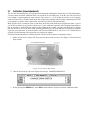
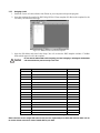
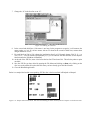
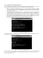
At the opening screen of the Spec Upload program, you have the option to Load the Default Setting file; load
from a named, saved file on your computer; or read the spec settings from the DC-200/300 scale connected to
your computer.
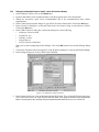
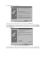
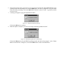
Select the radio button for Read From Scale. Also make sure that the Scale No. radio button for 192.168.0.1 (the
IP address of the DC-300) has been selected if you are using the DC-300 or 192.168.0.2 if you are using the
DC-200.
Figure 2-5. Read From Scale Screen
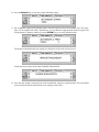
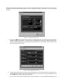
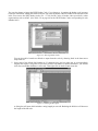
5. Click on the Next button at the bottom of the Spec Setting dialog box. The program will confirm Spec
reading in progress, please wait..., showing that it is uploading the current spec settings from the scale.
The Spec Upload program will next display the Spec Setting screen, showing the values of the first four
SPECs programmed in the scale.
Figure 2-6. User Specification Screen
6. To change the setting of one or more of the first four specs, use the pull down list box for that spec to
choose among the available settings for that specification. To move to the next four specifications, click
on the Next button at the bottom of the dialog box.
7. Once you have made all the needed changes to the specifications, you can upload the changed specs to
the scale and also save the new configuration to a named file on your computer for future updating of this
scale or matching the specifications on another DC-200/300.
To save the new configuration settings, click on the Save button at the bottom of the dialog box. You will
be prompted to give this configuration a file name. The next time you open the DC-300 Spec Upload
program, this file will show as one of the ones available to upload to any DC-200/300. After assigning a
file name, click on the Save button to save the file. You will be returned to the main Spec Upload Utility
screen.
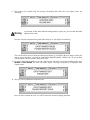
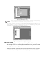
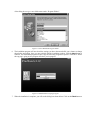
8. To upload the changed spec settings to the DC-200/300 currently connected to your computer, click on
the Upload button. The utility will ask you whether you want to update one specific spec or all the specs.
Figure 2-7. Upload Screen
To update only one spec, type its number into the box. To update all the specifications, select the radio
button for All Specifications. Click on the Upload button.
9. The program will confirm with the message Successfully Sent while the scale display shows the
following.
Warning
If you power off the scale while the saving process in going on, you can clear the entire
memory of the scale!
Once the scale has completed the upload of the change(s), it will display the following:
The scale should be powered down and then powered back up to initialize the new changes. When the
scale is powered back up, it will still be in the DATA TRANSFER MODE - READY state. To exit the Data
Transfer Mode, continue with the instructions below.
10. To exit the Data Transfer Mode on your DC-200/300 scale and return it to normal weighing mode, press
REZERO + SHIFT DOWN. The scale will briefly display a message saying that it is exiting the Data
Transfer mode.
11. Next you will be prompted to restart the scale.
Once you have restarted the scale, you will be returned to normal weighing operations.
Uploading Saved Spec Configurations to a DC-200/300
To download the spec settings from a DC-200/300 to the computer, see Section 2.9. If you already have a saved
configuration file of spec settings, use the instructions below to upload the settings to a DC-200/300. This could
be to change the settings of a DC-200/300 to fit a particular task, department or facility or it could be to take the
spec settings configuration from one DC-200/300 and upload it to other DC-200/300’s so that their settings
match.
1. With the scale turned on and at the Stand-by screen, press REZERO + SHIFT UP. The scale display will
indicate that it is changing to the data transfer mode.
2. The scale display will next indicate that it is ready for the data transfer mode after the scale is restarted.
Turn the scale off and then on again, using the on/off switch located on the bottom of the scale at the
back.
3. After you restart the scale and it goes through its startup sequence, the scale will show that the data
transfer mode is ready.
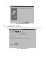
4. On your computer, open the Spec Upload program.
Note: If you have not yet installed the DC-300 Utility Programs, see “Installing the DC-300 Utility Program”.
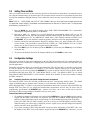
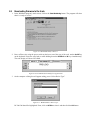
Figure 2-8. Load From File Screen
At the opening screen of the Spec Upload program, you have the option to Load the Default Setting file; load
from a named, saved file on your computer; or read the spec settings from the DC-200/300 scale connected to
your computer.
• to load the default specification settings to the scale, click the radio button next to Load Default Setting.
When you installed the DC-300 Utility Program a file named Default.ini was copied into the Digisoft
folder on your computer. To see what the default settings are for the scale specifications, see Section 2.5.
• to load a specification file you have previously saved to your computer, select the radio button for Load
From File. If the named file you want to upload to the scale appears in the File Name box, click on it to
select it. If the file you want does not appear in the File Name box, use the Drives and Folders explorer
windows to find the file you are looking for.
Once you have selected the spec configuration file to be uploaded and it appears under File Name, click
on the Next button at the bottom of the screen to continue.
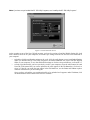
5. In the next screen you have the option to change any of the spec settings saved in this file before
uploading.
Figure 2-9. User Specification Screen
To upload to the scale without making any changes, click on the Upload button. To change the setting of
one or more of the first four specs, use the pull down list box for that spec to choose among the available
settings for that specification. To move to the next four specifications, press the Next button at the bottom
of the dialog box.
6. Once you have made all the needed changes to the specifications, you can upload the changed specs to
the scale and also save the new configuration to a named file on your computer for future updating of this
scale or matching the specifications on another DC-200/300.
To save the new configuration settings, click on the Save button at the bottom of the dialog box. You will
be prompted to give this configuration a file name. The next time you open the DC-300 Spec Upload
program, this file will show as one of the ones available to upload to any DC-200/300. After assigning a
file name, click on the Save button to save the file. You will be returned to the main Spec Upload Utility
screen.
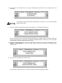
7. To upload the changed spec settings to the DC-200/300 currently connected to your computer, click on
the Upload button. The utility will ask you whether you want to update one specific spec or all the specs.
To update only one spec, type its number into the box. To update all the specifications, select the radio
button for all specifications. Click the Upload button.
Figure 2-10. Upload Spec Settings
8. The program will confirm with the message Successfully Sent while the scale display shows the
following.
Warning
If you power off the scale while the saving process in going on, you can clear the entire
memory of the scale!
9. Once the scale has completed the upload of the change(s), it will display the following:
The scale should be powered down and then powered back up to initialize the new changes. When the
scale is powered back up, it will still be in the DATA TRANSFER MODE - READY state. To exit the Data
Transfer Mode, continue with the instructions below.
10. To exit the Data Transfer Mode on your DC-200/300 scale and return it to normal weighing mode, press
REZERO + SHIFT DOWN. The scale will briefly display a message saying that it is exiting the Data
Transfer mode.
11. Next you will be prompted to restart the scale.
Once you have restarted the scale, you will be returned to normal weighing operations.
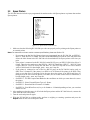
2.10 Modes of Operation
The DC-200/300 has four main modes of operation:
• Operation Mode – where all the basic weighing and counting operations are performed (also called the
Registration Mode).
• Report Mode – where item, inventory, and shelf location reports can be printed.
• Program Mode –where item data, factory name, and other data can be programmed into the memory of
the scale.
• Password Mode – where you can set passwords that will be required for a scale operator to use certain
functions of the scale.
A fifth mode of operation, Service Mode, is used by your DIGI Dealer or authorized service technician to
perform initial programming and troubleshooting operations.
Which mode you are in is displayed on the right-hand side of the display panel by the following codes:
Mode
Operation Mode
Annunciator
Default mode, no letter displayed
Report Mode
X
Program Mode
S
Password Mode
The code for the mode you are password protecting is displayed
Service Mode
Z
Table 2-3. DC-200/300 Modes of Operation
3.0
Maintenance
The following section describes basic maintenance involved with the DC-200/300 counting scale.
3.1
Hardware Testing
3.1.1
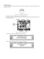
RAM and Communications Port Testing
In the Service Mode you can cycle through a set of hardware tests that will check reading/writing to RAM, the
RS-232 and Ethernet ports, and the ROM Checksum. If any of these tests fails, contact Rice Lake Weighing
Systems for help in determining the problem.
RAM Test
1. From the Stand-by Screen press the MODE key until the display shows SERVICE MODE. The Z
annunciator, indicating that you are in the service Mode will illuminate.While holding down the
REZERO key, press 001 to enter the hardware testing mode.
2. The first test is the RAM Read/Write Test. While the test is under way, the following is displayed.
If reading and writing to the scale’s RAM test successfully, the display reads:
If the read/write test is unsuccessful, the display will read:
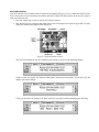
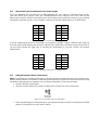
RS-232 Main Port Test
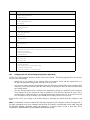
In order to perform the RS-232 port testing, you will need to have or make two test connectors with pins 4 and 5
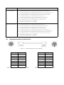
connected as follows:
Figure 3-1. Test Connector for RS-232 Ports
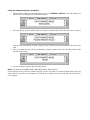
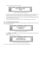
1. Press the + (plus) key. The display shows SIO LOOP BACK TEST.
2. Plug the test connector into the RS-232 port in the main interface board (the lower RS-232 port, next to
the IBM keyboard port.
Figure 3-2. DC-200/300 Interface Ports
If the port tests correctly, the following message is displayed.
If the loop back test of the port fails, you will see the following:
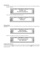
RS-232 Option Card Test
Your DC-200/300 comes standard with the option board installed that gives you two additional RS-232 ports.
You will need the two test connectors described in the RS-232 Main Test Port section on the previous page in
order to perform this test.
1. Press the + (plus) key to move to the RS-232 Option Card test.
2. Plug the RS-232 test connectors into both of the ports on the option card (the two upper RS-232 ports
next to the Ethernet port marked SIO1 and SIO2).
Figure 3-3. Option Board RS-232 Ports
The scale will perform the test. If it completes successfully, you will see the following display:
If the test fails, the display will indicate which port(s) did not test successfully. If both ports fail, the
display will read as follows:
If only one port fails, the message will show which one was unsuccessful by displaying the following:
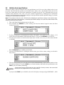
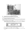
Ethernet Port Test
1. Press the + (plus) key to move to a test of the Ethernet port. If the port tests successfully, the following
message is displayed.
If the test fails, the scale displays the following screen:
ROM Checksum Test
Press the + (plus) key to move to the ROM Checksum test for the firmware. While the test is being performed,
you will see;
When the test completes successfully, the scale display will switch to:
Exiting the Hardware Test Mode
At this point you can press the + (plus) key again to repeat the cycle of hardware test beginning with the RAM
test, or you can press the TARE key to return to the Service Mode. Then press the MODE key twice to return to
the Stand-by screen.
3.1.2
Internal Test Count
This test allows you to see more detail on the scale’s internal resolution than you can see on the weight and
counting display. It may allow you to tell if there is a problem with the load cell being misaligned or if something
is rubbing against a load cell during weighing operations. If the scale constantly does not return to zero during
weighing, you can also rezero the internal counting using this procedure.
1. From the Stand-by screen, press the MODE key until the display shows SERVICE MODE. The Z
annunicator, indicating that you are in the Service Mode, illuminates.
2. While holding down the REZERO key, press 009 to start the Internal Count test. The scale display shows
the results of the test:
If the number on the left is not returning to zero, press the REZERO key. Place a weight on the scale
platform. If the scale does not respond quickly and repeatedly by increasing the counts when you place a
weight on the scale, you may want to check the load cells.
3. Press the TARE key to return to the SERVICE MODE. Then press the MODE key twice to return to the
Stand-by screen.
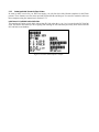
3.1.3
Span Switch Status Test
From the Stand-by screen, press the MODE key until the display shows SERVICE MODE. The Z annunicator,
indicates that you are in the Service Mode and illuminates.
1. While holding down the REZERO key, press 284 to display the Span Switch status. The scale display
shows the current status of the Span Switch.
2. Press the TARE key to return to the Service Mode. Then press the MODE key twice to return to the Standby screen.
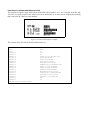
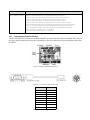
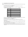
3.1.4
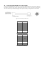
Voltage Checkpoints
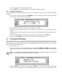
There are four voltage checkpoints on the main board. Below are listed the reference voltage levels commonly
used.
Voltage Point
Voltage
Purpose
Vcc
5.0 V
Provides voltage for most of the IC
V TH
24 V
Provides voltage primarily to the thermal print head
V BB (off state)
2.5 V
Provides backup voltage for the RAM IC when the power is off
V BB (on state)
4.5 V
Provides backup voltage for the RAM IC when the power is on
Table 3-1. Voltage Checkpoints
The tolerance of all the voltages shown is about ± 5%, except V TH which is +2% and -5%.
Figure 3-4. Voltage Checkpoints
3.2
Internal Printer Tests and Adjustments (DC-300 only)
The following sections describe internal printer tests and the appropriate adjustments.
3.2.1
Checking or Rezeroing the Thermal Head Usage Counter
The DC-300 maintains a usage counter for the thermal head of the built-in printer. It displays the usage in
thousands (incrementing 1 for every 1000 print operations). The counter can be rezeroed after the replacement of
the print head in order to track usage on the new one.
1. From the Stand-by screen, press the MODE key until the display shows SERVICE MODE. The Z
annunicator, indicating that you are in the Service Mode, lights. While holding down the REZERO key,
press 0823 to display the Thermal Head Usage Counter.
In the example shown above, the counter is indicating that 47,000 print operations have taken place.
2. To rezero the counter, press the CLEAR key followed by the CODE key.
3. Press the TARE key to return to the Service Mode. Then press the MODE key twice to return to the Standby screen.
3.2.2
Adjusting the Printer Label Gap Sensor
The built-in printer in the DC-300 has a label gap sensor designed to detect the gap between labels on a label roll.
This allows the printer to identify the starting position of each label so that only one label is issued at a time
during a print operation.
Figure 3-5. Label Gap Sensor
A resistor detects a variation in voltage between the label and the backing paper.
Figure 3-6. Label Gap Sensor Resistor Location
Depending on the material of the label and the backing material of the label roll, labels will have a gap sensor
voltage of between 2.5 V and 5.0 V while the backing material will have a gap sensor voltage of between 1.0 V
and 2.5 V. If the printer begins to misfeed labels, the voltage threshold can be reset as described below.
Threshold Voltage
The sensor needs a threshold voltage (also called a gap reference voltage) at which it can distinguish between a
label and a gap between labels. Any portion on the roll with a gap sensor voltage above the threshold voltage will
be considered by the printer to be a label, while portions of the roll below the threshold voltage will be
considered gaps between labels. The threshold voltage is computed according to the following formula:
Threshold Voltage = (highest detected value + lowest detected value) / 2
The threshold voltage is computed automatically by the scale whenever the FEED key is pressed. However, it the
printer is misaligning the labels because it does not accurately detect the gap, the threshold voltage can also be
set manually.
1. At the Stand-by screen, hold down the REZERO key while entering 516 to enter the Threshold Voltage
Setting mode. The following will appear on the display.
Figure 3-7. Gap Sensor Voltage Adjustment
2. You can test the voltage variation between the label and the backing by manually pulling labels past the
sensor. The voltage level of the label should be low while the voltage of the backing material in the gap is
high. Note the voltages on the display for the label stock you are using.
3. Use the << and >> keys to adjust the Threshold Voltage used by the printer. Set the threshold at the
midpoint between the readings you noted for the labels and the backing material on your label stock.
4. To exit the Threshold Voltage Setting mode and return to the Stand-by screen, press the TARE key.
Peel Sensor Voltage
When label stock is loaded into the DC-300’s built-in printer, you can choose to have the labels print out with the
label backing intact or to print with the label partially peeled off of the backing. (See the DC-300 Operation
Manual for information on how to load the labels for peel-off and the SPEC settings involved.) Similar to the
Gap Sensor’s Threshold Voltage (see Section 3.2.2), the Peel Sensor determines where the end of the label is so
that the backing is peeled off just to the right point.
Figure 3-8. Peel Sensor Adjustment Location
During normal operation, the Peel Sensor Voltage is set automatically by pressing the FEED key. Sometimes,
however, changes in temperature or humidity cause the sensor to misread the label position. If labels are not
peeling off completely or if the peel off position is going over into the next label, the Peel Sensor Voltage can be
adjusted by following the procedure below:
1. At the Stand-by screen, hold down the REZERO key while entering 515 to enter the Peel Voltage Setting
mode. The following will appear on the display.
2. At this point you’ve got three choices:
• Press the REPRINT key to have the scale automatically reset the voltage value and exit to the Stand-by
screen.
• Enter a numeric value for a new Peel Sensor Voltage using the numeric keys. Then press the CODE key
•
3.2.3
to save the change and exit to the Stand-by screen.
Press the TARE key to exit to the Stand-by screen without making any changes.
Adjusting the Printing Position
If the thermal print head gets misaligned vertically, the vertical position can be adjusted using the following
procedure.
1. At the Stand-by screen, hold down the REZERO key while entering 514 to enter the Adjust Printing
Position mode. The following message appears:
2. Print positions are measured in dots, where 1 vertical dot = 0.155mm.
• To adjust the print position upward, enter the number of dots you want to move from the numeric
keypad.
• To adjust the print position downward, enter the number of dots from the numeric keypad and press the (minus) key.
• To exit the Adjust Printing Position mode without making any changes, press the TARE key.
3. Finally, press the CODE key to store the new value and exit to the Stand-by screen.
3.3
Clearing the Scale Memory
This procedure allows you to clear the static RAM and all the Item, Inventory, and Label Format files. You may
want to use the DC-300 Utility Program to copy your scale specifications settings and item files to a PC and save
them so that they can transferred to another scale or re-downloaded to the scale whose memory you are clearing.
(See DC-200/300 Operation Manual).
1. Power off the scale.
2. Power the scale back on while simulatenously pressing both the REZERO and TARE keys. The display
will offer you the choice of clearing the memory or exiting without clearing the RAM and intializing the
scale.
Caution
This procedure will erase all Item, Inventory, and Label Formatting information in your scale. Be
sure that this is what you want to do before proceeding.
3. Press the CLEAR key to clear the memory or press the TARE key to exit without clearing the memory and
simply return to the Stand-by screen in Weighing Mode. If you choose to clear the memory, the scale
display will show the message, PLEASE WAIT... until the procedure is done.
Do not power off the scale while the memory clearing operation is in process.
4. Once the memory is cleared, the scale will go through its standard start-up segment check and then
return to the Stand-by screen in the Weighing Mode.
3.4
Technical Drawings
3.4.1
DC-300 Exploded View
Figure 3-9. DC-300 Exploded View
3.4.2
DC-300 Block Diagram
Figure 3-10. DC-300 Block Diagram
3.4.3
DC-200 Block Diagram
Figure 3-11. DC-200 Block Diagram
4.0
Assembly/Disassembly of the DC-200/300
The following instructions show the procedures for disassembling various parts of the scale to replace the display
board, keyboard circuit board, interface main board, printer drawer block, and internal printer thermal head.
4.1
Removing the Main Cover
1. First, remove the stainless steel weighing platter from on top of the spider.
Figure 4-1. Disassembly - Remove Platter
2. Next unscrew the four screws that hold the platter support, and remove the platter support.
Platter support screws x 4
Four corner screws
(two not visible) and
front panel screws
Figure 4-2. Remove Platter Support and Case Screws
Also unscrew the screws at the four corners and the two screws underneath the front of the display panel.
3. Pull the main cover gently up, but not all the way off of the scale. Reach in and unplug the keyboard
connector from the main board as well as the connectors from the display to the cover. Then you can lift
the cover all the way off the scale and set it aside.
Figure 4-3. Main Cover Removed
4.2
Disconnecting the Display Board
The display board is inside the main scale cover. Before following the steps listed below, you have to remove the
main cover assembly as described in Section 4.1.
1. Remove the screws circled in Figure 4-4 which hold the display assembly in place.
Figure 4-4. Display Assembly Screws
2. After removing the display assembly from the main cover, remove the four screws shown below to
separate the display board from the rest of the display assembly.
Figure 4-5. Display Board Screw Location
3. Gently separate the display board from the rest of the display assembly.
Figure 4-6. Display Board Back View and Display Board Front View
Figure 4-7. Display Board Front View
4.3
Disconnecting the Keyboard Circuit Board
In order to disconnect the Keyboard Circuit Board, you must first have removed the scale’s Main Cover (see
Section 4.1) and removed the Display Board Assembly (see Section 4.2 above).
1. Unscrew the six screws holding the keyboard circuit board to the scale cover.
Figure 4-8. Keyboard Circuit Board Screw Location
2. Gently remove the keyboard circuit board from the cover.
Figure 4-9. Keyboard Circuit Board Front View
4.4
Removing the Interface Main Board
In order to carry out this procedure, you must first have removed the scale’s Main Cover as described in
Section 4.1.
1. Unscrew the three screws shown in Figure 4-10 which allow you to remove the housing covering the
interface ports.
Figure 4-10. Remove Interface Port Cover
2. Disconnect the Interface Main Board from the scale’s main board attached to the base.
Figure 4-11. Separate the Interface Main Board from the Main Board
3. Gently remove the interface main board.
Figure 4-12. Removing the Interface Main Board
4.5
Removing the Printer Drawer Block (DC-300 only)
1. Disconnect the connector from the printer to the Main Board, as shown below.
Figure 4-13. Disconnect Printer From Main Board
2. To remove the drawer block, simultaneously push the two triggers on the printer drawer block tray.
Figure 4-14. Printer Drawer Block Tray Triggers
The printer block, when removed, looks as follows:
Figure 4-15. Printer Drawer Block Removed
4.6
Removing the Thermal Print Head (DC-300 only)
1. Open the printer drawer block.
2. Remove the screw holding the print head assembly in place.
Figure 4-16. Printer Head Assembly Screw
3. Turn the metal plate counter-clockwise. Then move the paper lead roller out of the way.
4. Disconnect the two cables going to the printer head.
Figure 4-17. Disconnect Printer Cables
5. Remove the two Allen screws holding the thermal print head in the printer head assembly.
Figure 4-18. Printer Head Allen Screw Location
6. Pull the thermal print head out vertically from the print head assembly.
Figure 4-19. Removing the Thermal Print Head
Figure 4-20. Thermal Print Head
5.0
Network and Interfaces: External Printers
5.1
Connecting an External Printer to the Scale
5.1.1
Spec Settings for External Printers
In order for the DC-200/300 scale to recognize an external printer properly and send data to it, there are customer
specifications which must be set properly. The settings depend on which of the RS-232C ports you are
connecting the printer to: the “main” RS-232C port or one of the “option ports” SIO1 or SIO2.
If the printer is connected to the main port (next to the keyboard port), the settings should be as follows:
Note: For instructions on how to set the customer specifications, please see Section 2.9.
• SPEC 15: SIO SELECT JOB to 3: PRINTER
• SPEC 16: BAUD RATES (SIO) to the proper baud rate for your application
• SPEC 17: DATA LENGTH (SIO) to the proper length for your application
• SPEC 18: PARITY BIT (SIO) to the proper setting for your application
• SPEC 19: STOP BIT (SIO) to the proper setting for your application
• SPEC 32: TYPE OF PRINTER to the type of external printer you are using
If the printer is connected to one of the option ports, the spec settings depend upon what else you have connected
to the other port. These two RS-232C ports are set in tandem using SPEC 20: RS232 OPTION CARD. Possible
combinations include the following:
Note: For instructions on how to set the customer specifications, please see Section 2.9.
If connecting to...
Set specs as follows...
a force balance on SIO1 SPEC 20: RS232 OPTION CARD to “1: PRN (DIN2) - FB (DIN1)
an external printer on SIO2 SPEC 21: BAUD RATE (DIN1) to the appropriate baud rate for the force balance
SPEC 22: DATA LENGTH (DIN1) to the appropriate number of bits for the force balance
SPEC 23: STOP BIT (DIN1) to the appropriate number of bits for the force balance
SPEC 24: PARITY BIT (DIN 1) to the appropriate odd or even for the force balance
SPEC 25: BAUD RATE (DIN2) to the appropriate baud rate for the printer
SPEC 26: DATA LENGTH (DIN2) to the appropriate number of bits for the printer
SPEC 27: STOP BIT (DIN2) to the appropriate number of bits for the printer
SPEC 28: PARITY BIT (DIN 1) to the appropriate odd or even for the printer
SPEC 29: RS232C CONNECT FB to “1: ENABLE”
SPEC 30: TYPE OF FORCE BAL to “0: EXPORT”
SPEC 32: TYPE OF PRINTER to the appropriate setting for the printer you are connecting
an external printer on SIO1 SPEC 20: RS232 OPTION CARD to “2: FB (DIN2) - PRN (DIN1)
a force balance on SIO2 SPEC 21: BAUD RATE (DIN1) to the appropriate baud rate for the printer
SPEC 22: DATA LENGTH (DIN1) to the appropriate number of bits for the printer
SPEC 23: STOP BIT (DIN1) to the appropriate number of bits for the printer
SPEC 24: PARITY BIT (DIN 1) to the appropriate odd or even for the printer
SPEC 25: BAUD RATE (DIN2) to the appropriate baud rate for the force balance
SPEC 26: DATA LENGTH (DIN2) to the appropriate number of bits for the force balance
SPEC 27: STOP BIT (DIN2) to the appropriate number of bits for the force balance
SPEC 28: PARITY BIT (DIN 1) to the appropriate odd or even for the force balance
SPEC 29: RS232C CONNECT FB to “1: ENABLE”
SPEC 30: TYPE OF FORCE BAL to “0: EXPORT”
SPEC 32: TYPE OF PRINTER to the appropriate setting for the printer you are connecting
If connecting to...
Set specs as follows...
a PC on SIO1
SPEC 20: RS232 OPTION CARD to “3: PRN (DIN2) - PC (DIN1)
an external printer on SIO2 SPEC 21: BAUD RATE (DIN1) to the appropriate baud rate for the PC
SPEC 22: DATA LENGTH (DIN1) to the appropriate number of bits for the PC
SPEC 23: STOP BIT (DIN1) to the appropriate number of bits for the PC
SPEC 24: PARITY BIT (DIN 1) to the appropriate odd or even for the PC
SPEC 25: BAUD RATE (DIN2) to the appropriate baud rate for the printer
SPEC 26: DATA LENGTH (DIN2) to the appropriate number of bits for the printer
SPEC 27: STOP BIT (DIN2) to the appropriate number of bits for the printer
SPEC 28: PARITY BIT (DIN 1) to the appropriate odd or even for the printer
SPEC 32: TYPE OF PRINTER to the appropriate setting for the printer you are connecting
an external printer on SIO1 SPEC 20: RS232 OPTION CARD to “4: PC (DIN2) - PRN (DIN1)
a PC on SIO2
SPEC 21: BAUD RATE (DIN1) to the appropriate baud rate for the printer
SPEC 22: DATA LENGTH (DIN1) to the appropriate number of bits for the printer
SPEC 23: STOP BIT (DIN1) to the appropriate number of bits for the printer
SPEC 24: PARITY BIT (DIN 1) to the appropriate odd or even for the printer
SPEC 25: BAUD RATE (DIN2) to the appropriate baud rate for the PC
SPEC 26: DATA LENGTH (DIN2) to the appropriate number of bits for the PC
SPEC 27: STOP BIT (DIN2) to the appropriate number of bits for the PC
SPEC 28: PARITY BIT (DIN 1) to the appropriate odd or even for the PC
SPEC 32: TYPE OF PRINTER to the appropriate setting for the printer you are connecting
Table 5-1. Spec Settings for RS232C Ports SIO1 and SIO2
5.1.2
Connecting the Printer to the RS-232C Port
The DC-200/300 can be connected to an external printer using one of the RS-232C ports on the scale, either the
main port next to the keyboard port or one of the option ports next to the Ethernet port (SIO1 and SIO2).
Figure 5-1. DC-200/300 Interface Ports
The DC-200/300 can be connected to an external printer using one of the RS-232C ports on the scale.
Figure 5-2. Connection from Scale to Printer
Pin Number
Description
1
2
RXD
3
TXD
4
5
GND
6
7
RTS
8
CTS
9
Table 5-2. Nine-Pin DIN Connector- External Printer
Pin Number
Description
1
2
GND
3
4
RXD
5
TXD
6
CTS
7
RTS
8
Table 5-3. Eight-Pin DIN Connector - DC-200/300
5.2
Eltron Printers
The instructions below will walk you through how to design a label using the Create-A-Label software that
comes with the Eltron printers using the DIGI template, download the template you have designed to the printer
and connect the printer to the DC-200/300. These instructions refer to version 3.04 of the Eltron Create-A-Label
software.
5.2.1
1.
2.
3.
4.
5.
6.
7.
Set the Computer Serial Port
In Windows, click on the Start button.
Go up to the Settings menu and select Control Panel.
Double-click on the System icon.
Select the tab for Device Manager.
Double-click on Ports (COM & LPT)
Double-click on Communications Port (COM 1)
Click on the Port Settings tab and set the following parameters:
• Bits per second: 9600
• Data bits:
8
• Parity:
None
• Stop bits:
1
• Flow control:
Hardware
8. Close the Communications Port (COM 1), Properties, and Device Manager dialog boxes by clicking on
the OK buttons.
5.2.2
Designing a Label
1. Install the Create-A-Label software from Eltron on your computer and open the program.
2. Open the template file supplied by DIGI (Digi DC300- Eltron template.lbl). Resize the template for the
size label you would like to design.
Figure 5-3. Hidden Fields on the Eltron Template
3. Open the Edit Menu and select Label Setup. You will see that the DIGI template includes 17 hidden
fields which appear in red in the template.
Caution
Do not alter the hidden fields while designing your label. Changing or deleting the hidden fields
will cause the label to print incorrectly or not at all.
V#
Variable Name
DIGI Header
V00
ID Code (32 Characters)
3
V01
Quantity
2
V02
Gross Weight
A
V03
Net Weight
0
V04
Tare Weight
4
V05
Sequence No.
none
V06
Date and Time
none
V07
Alternate Part No. (32 Characters)
M
V08
Part Name (32 Characters)
N
V09
Weight per 1000 pieces
1
V10
Number of Transactions
none
V11
Quantity in Accumulation
I
V12
Lb, Kg, or g
none
V13
Weight per 1000 pieces
1
V14
Tare Weight
4
V15
Pieces in Inventory
K
V16
Lot Number (32 Characters)
E
Table 5-4. Hidden Fields for the Eltron Label Program
Note: There are two tare weight fields (V04 and V14) and two weight/1000 pieces fields (V09 and V13). Either one can
be used to include a barcode or human readable field on your label.
4. To add items to your design, select the Draw menu and choose either text, bar code, line or box.
• Line or Box - you can use the drawing tools to put separator lines or boxes around elements on the
label.
• Text - text can either be fixed or linked.
• Fixed text is not linked to the data output from the scale. This can be used for titles, addresses and
other information where whatever you enter is what you want to appear on the label.
• Linked text fields will print the data output from the scale for that field.
• Barcodes- barcodes are always linked to data from the scale output.
• Pictures - pictures such as logos can be imported in PCX format and resized on the label screen.
Adding a Text Field
1. Select the Draw Menu and choose Text.
2. Set the font weight, height and width expansion, and rotation characteristics of the text field you want to
appear on your label.
3. To add fixed text to the label (text such as titles or addresses not linked to the data output from the scale,
select fixed from the drop-down list box labeled data source. Then in the text string box enter the fixed
text you want to appear on the label. To link the text field to output from the DC-200/300 scale, select
linked in the data source box, then select the field to link to from the linked fields drop-down list box.
Adding a Barcode Field
1. Select the Draw Menu and choose Barcode.
2. Set the Bar Code symbology in bar code type. Here you can also set whether or not you want a
human-readable (numeric) representation of the barcode to appear underneath it.
3. Next, set the rotation, bar-width ratio, and multiplier, of the new field.
4. Bar codes will usually be linked to output from the DC-200/300 scale so select linked in the data source
drop-down list. Then, in the linked fields parameter you can select the field from the scale output to link
to from its drop-down list. (Table 5-4 for the fields you can link to).
Figure 5-4. Choosing Fields to Link
You can also choose to insert the DIGI Header Code, if you choose to, by putting the header code in quotes
before the linked field. Adding the header code here will cause the header code to be added to the barcode on the
label. You can use the DIGI header codes (Ex. “3”V00 for ID Code) or header codes specified by other
organizations such us AIAG. (See Table 5-4 on page 60 for the DIGI Header Codes corresponding to each
linkable field.)
Figure 5-5. Entering Header Codes
You can also add a barcode not linked to output from the scale by choosing fixed in the data source
drop-down list.
5. Since some of the default field lengths are 32 characters long, the bar codes may be correspondingly
lengthy and require a long label. If you don’t need the full number of default characters, you can left
click once on a hidden field that is a bar code. Then right-click on the field and select edit.
Figure 5-6. Editing Field Lengths
A dialog box will open which includes a string length you can edit. Reducing the field size will decrease
the length of the bar code.
Figure 5-7. Reducing String Lengths
Caution
DO NOT change the default field size for the bar codes for Tare, Net Weight, or Unit Weight. Doing
so may cause them to be unreadable when scanning them into the scale.
6. You can place the new bar code field over top of the hidden fields on the label template. However, when
editing or changing any of your new fields, be sure not to select a hidden field. Deleting or changing the
hidden fields will cause the label to print incorrectly or not at all.
Figure 5-8. Placing Items Over the Top of the Hidden Fields
Adding a Picture or a Graphic
You may want to add a company logo or other picture to your label design. To do so, follow these steps:
1. Save the graphic or picture in the .PCX format (Microsoft Paintbrush) and copy or move the file into the
“PCX” folder of the Create-A-Label directory. If you chose the default directory when you installed the
software it will be at C:\CAL3.304\PCX.
2. Select the Draw Menu and choose Picture.
3. In the Pictures dialog box, set the rotation, and ratio for the graphic and picture. Set the data source to
fixed.
4. In the pictures field, use the drop-down list box to select the graphic or picture you want on the label.
If you have clicked on the preview check box, the graphic or picture will appear in the preview pane.
Figure 5-9. Inserting a Picture or a Graphic
5. After you click the OK button in the Pictures dialog box you will be returned to the main label design
screen. The cursor will change to be a box the size of the graphic or picture you are inserting on the label.
Move the box to the place on the label that you want it to appear and click to place it there. You can click
on and drag the graphic to another position on the label and you continue to work on your design.
Resizing it can be accomplished by dragging on the handles around the graphic.
6. Downloading a graphic to the Eltron printer requires an extra step (see Section 5.2.3, Step 2).
5.2.3
Saving the Label Format You Have Made
1. When you have completed the label design, open the File Menu and choose the Save As option. You will
want to rename the file to a name different from the default, both so that you don’t overwrite the basic
DIGI template and so that you can distinguish it from other designs you may format. After you have
renamed the label design, click on the Save button.
2. If your label format does not have any pictures or graphics, you can skip to Step 3 of this section. If your
label design contains a picture or graphic, open the File Menu and select Download to Printer. In the
dialog box, select the file name for the label you want to download. Click on the Download button to
send the file to the Eltron printer.
Note: This procedure downloads the picture or graphic to the printer. To download the text and barcode fields to
the printer in a form that will work with the DC-200/300 counting scale, you need to follow Steps 3-10 below.
3. After the label is saved under a new file name, open the File Menu again and select Generate EPL Source
File. A Print To dialog box will appear showing your label file name with a .BIN extension. Click the OK
button. Next another dialog box will appear showing your label file name with an .EJF extension. Click
the OK button.
Note: The .BIN and .EJF filenames can only be 8 characters long, excluding the .BIN or .EJF extensions.
4. Close the Create-A-Label application.
5. Open the Start Menu, select Programs, then select Accessories. Under Accessories, select either the
Wordpad or Notepad applications.
6. In Wordpad or Notepad, open the .EJF file you created in Step 2 above.
7. Change the “O” in the first line to an “N”.
Figure 5-10. Editing the .EJF File
8. In the second and third lines, if the name is too long for the program to recognize, it will truncate the
name, putting a x in it. If you have names with an x in them in the second or third lines, rename them
using 8 characters or less.
9. For each line from V00 to V16, change the justification from L to N. Example: change V00, 32, L, ““ to
V00, 32, N,””. You can edit the lines manually or, if you are familiar with the function, use the Replace
function under the Edit Menu in WordPad.
10. At the end of the .EJF file, insert a line before the last line FE and enter PA1. This tells the printer to print
one label.
11. Save the .EJF file you have edited by opening the File Menu and clicking on Save or by clicking on the
disc icon on the toolbar. Keep the same file name you have already given this label format.
12. Close the WordPad application.
Below is a sample label and the corresponding .EJF file after it has been edited in Wordpad or Notepad.
Figure 5-11. Sample Label Format From .EJF File Downloading the Label Format from the Computer to the Eltron Printer
N
FK”DIGIDC2"
FS”DIGIDC2"
V00, 32, N, ""
V01, 10, N, ""
V02, 6, N, ""
V03, 6, N, ""
V04, 6, N, ""
V05, 8, N, ""
V06, 32, N, ""
V07, 32, N, ""
V08, 32, N, ""
V09, 6, N, ""
V10, 4, N, ""
V11, 8, N, ""
V12, 4, N, ""
V13, 6, N, ""
V14, 6, N, ""
V15, 8, N, ""
V16, 32, N, ""
q816
Q1015, 24+0
S2
D8
ZT
TTh:m
TDy2.mn.dd
A39, 946, 3, 1, 4, 3, N, "ID CODE"
A39, 700, 3, 1, 4, 2, N, V00
B93, 950, 3, 3, 2, 4, 101, B, "3"V00
A256, 954, 3, 1, 4, 2, N, "QUANTITY"
A260, 721, 3, 1, 4, 2, N, V01
B254, 451, 3, 3, 2, 4, 101, B, V01
A404, 956, 3, 1, 4, 2, N, "TARE"
A414, 796, E, 1, 4, 2, N, V04
B398, 443, 3, 3, 2, 4, 101, B, "4"V04
A568, 956, 3, 1, 4, 2, N, "UNIT WEIGHT"
A568, 619, 3, 1, 4, 2, N, V12
B548, 436, 3, 3, 2, 4, 101, B, "1"V13
PA1
FE
Figure 5-12. Sample .EJF File in WordPad After Editing
5.2.4
Downloading the Label Format From the Computer to the Eltron Printer
1. Install the Eltrterm.exe download program supplied by DIGI and open it.
2. In the Eltrterm program open the CommPort Menu and select Properties.
3. In the CommPort Properties dialog box, set the serial protocol as follows:
• Port: Com1
• Printer: LP2742 (or other model as appropriate)
• Maximum Speed: 9600
• Echo: Off
• Data Bits: 8
• Parity: None
• Stop Bits: 1
• Flow Control: RTS
Once the serial protocol properties have been set, click on the OK button to save the changes.
4. Open the File Menu and select Open File to Send.
5. In the Open Communications Log File dialog box, select the directory path and .EJF file you previously
made in the Eltron Create-A-Label software. Then click on the Open button.
6. Use the pull-down menu on the Enter Download Label Name field to select the type of download you
want to send to the printer:
• Individual Label - the most commonly used. This will print a single label according to what you
specified in Create-A-Label.
• Total Label - this will print a label when totaling accumulations.
• NO ID Individual Label * + - will print an individual label without an ID Code when you press the *,
+ or - key (depending on how you have the DC-200/300 specs set.
• NO ID Total Label - same as Total Label but with no ID Code.
• NO WT Item Label - prints a label without weight data.
• NO ID NO WT Item Label - prints an Item label without ID Code or weight data.
Figure 5-13. Selecting Type of Download
7. Once you have selected the type of download, the label format will download to the printer.
8. Open the File Menu and select Exit to close the download program.
5.2.5
Predesigned Label Formats for Eltron Printers
In order to make it easier for you, DIGI can supply you with four basic label format templates for the Eltron
printers. These formats cover the most-used and requested fields and designs. You can also customize and reuse
these templates using the instructions in Section 5.2.2.
Label Format L1- Individual Label with ID Code
This template will print a single label with an Item ID Code when the *, + or - key is pressed on the DC-200/300
scale. It would be used when you are weighing and counting an item which has previously been entered into the
DC-200/300’s item database.
Figure 5-14. Eltron Label Template 1 Sample
The contents of the .EJF file for Eltron Label Format 1 are:
N
FK"L1"
FS"L1"
V00,32,N,"0"
V01,10,N,"1"
V02,10,N,"2"
V03,10,N,"3"
V04,10,N,"4"
V05,10,N,"5"
V06,30,N,"6"
V07,32,N,"7"
V08,32,N,"8"
V09,10,N,"9"
V10,10,N,"A"
V11,10,N,"B"
V12,10,N,"C"
V13,10,N,"D"
V14,10,N,"E"
V15,10,N,"F"
V16,32,N,"G"
Q808,0
R8,16
S2
D10
ZT
A118,0,1,4,1,1,N,"SEQ. NO: "V05
A90,0,1,4,1,1,N,V06
B430,0,1,3,2,7,57,N,"3"V00
A362,0,1,4,2,2,N,"ID.CODE:"V00
A62,0,1,4,1,1,N,"PART NO: "V07
A34,0,1,4,1,1,N,"LOT NO: "V16
A34,430,1,4,1,1,N,"PART NAME:"V08
A311,0,1,4,2,2,N,"QTY "
A311,120,1,4,2,2,R,V01
B311,430,1,3,2,7,57,N,V01
A248,430,1,4,1,1,N,"QUANTITY "V01
A244,0,1,2,2,3,N,"G "V02V12
A206,0,1,2,2,3,N,"N "V03V12
A168,0,1,2,2,3,N,"T "V04V12
B218,430,1,3,2,7,57,N,"1"V13
A155,430,1,4,1,1,N,"WT/1000 "V09
B125,430,1,3,2,7,57,N,"4"V14
A62,430,1,4,1,1,N,"TARE "V04
PA1
FE
Table 5-5. Sample .EJF File in WordPad After Editing
Label Format L2 - Individual Label Without an ID Code
This template will print a single label without an Item ID Code when the *, + or - key is pressed on the DC-200/
300 scale. It would be used in cases where you want an Item Label for an item you are weighing and counting
that is not in the DC-200/300’s item database.
Figure 5-15. Eltron Label Template 2 Sample
The contents of the .EJF file for Eltron Label Format 2 are:
N
FK"L2"
FS"L2"
V00,32,N,"0"
V01,10,N,"1"
V02,10,N,"2"
V03,10,N,"3"
V04,10,N,"4"
V05,10,N,"5"
V06,30,N,"6"
V07,32,N,"7"
V08,32,N,"8"
V09,10,N,"9"
V10,10,N,"A"
V11,10,N,"B"
V12,10,N,"C"
V13,10,N,"D"
V14,10,N,"E"
V15,10,N,"F"
V16,32,N,"G"
(continued at the top of the next column)
Q808,0
R8,16
S2
D10
ZT
A118,0,1,4,1,1,N,"SEQ. NO: "V05
A90,0,1,4,1,1,N,V06
A311,0,1,4,2,2,N,"QTY "
A311,120,1,4,2,2,R,V01
B311,430,1,3,2,7,57,N,V01
A248,430,1,4,1,1,N,"QUANTITY "V01
A244,0,1,2,2,3,N,"G "V02V12
A206,0,1,2,2,3,N,"N "V03V12
A168,0,1,2,2,3,N,"T "V04V12
B218,430,1,3,2,7,57,N,"1"V13
A155,430,1,4,1,1,N,"WT/1000 "V09
B125,430,1,3,2,7,57,N,"4"V14
A62,430,1,4,1,1,N,"TARE "V04
PA1
FE
Table 5-6. Sample Contents of .EJF File for Eltron Label Format 2
Label Format L3 - Total Label With an ID Code
This template will print a total label with an Item ID Code. It would be used when doing an accumulation on an
item which has previously been entered into the DC-200/300’s item database.
Figure 5-16. Eltron Label Template 3 Sample
The contents of the .EJF file for Eltron Label Format 3 are:
N
FK"L3"
FS"L3"
V00,32,N,"0"
V01,10,N,"1"
V02,10,N,"2"
V03,10,N,"3"
V04,10,N,"4"
V05,10,N,"5"
V06,30,N,"6"
V07,32,N,"7"
V08,32,N,"8"
V09,10,N,"9"
V10,10,N,"A"
V11,10,N,"B"
V12,10,N,"C"
V13,10,N,"D"
V14,10,N,"E"
V15,10,N,"F"
V16,32,N,"G"
(continued at top of the next column)
Q808,0
R8,16
S2
D10
ZT
A118,0,1,4,1,1,N,"SEQ. NO: "V05
A90,0,1,4,1,1,N,V06
B430,0,1,3,2,7,57,N,"3"V00
A362,0,1,4,2,2,N,"ID.CODE:"V00
A62,0,1,4,1,1,N,"PART NO: "V07
A34,0,1,4,1,1,N,"LOT NO: "V16
A34,430,1,4,1,1,N,"PART NAME:"V08
A311,0,1,4,2,2,N,"TTL QTY"
A255,2,1,4,2,2,R,V11
A200,0,1,4,1,1,N,"(X"V10")"
B311,430,1,3,2,7,57,N,V11
A248,430,1,4,1,1,N,"TTL QUANTITY "V11
PA1
FE
Table 5-7. Sample Contents of .EJF File for Eltron Label Format 3
Label Format L4 - Total Label Without an ID Code
This template will print a total label without an Item ID Code. It would be used when doing an accumulation on
an item which has not previously been entered into the DC-200/300’s item database.
Figure 5-17. Eltron Label Template 4 Sample
The contents of the .EJF file for Eltron Label Format 4 are:
N
FK"L4"
FS"L4"
V00,32,N,"0"
V01,10,N,"1"
V02,10,N,"2"
V03,10,N,"3"
V04,10,N,"4"
V05,10,N,"5"
V06,30,N,"6"
V07,32,N,"7"
V08,32,N,"8"
V09,10,N,"9"
V10,10,N,"A"
V11,10,N,"B"
V12,10,N,"C"
V13,10,N,"D"
V14,10,N,"E"
V15,10,N,"F"
V16,32,N,"G"
Q808,0
R8,16
S2
D10
ZT
A118,0,1,4,1,1,N,"SEQ. NO: "V05
A90,0,1,4,1,1,N,V06
A311,0,1,4,2,2,N,"TTL QTY"
A255,2,1,4,2,2,R,V11
A200,0,1,4,1,1,N,"(X"V10")"
B311,430,1,3,2,7,57,N,V11
A248,430,1,4,1,1,N,"TTL QUANTITY "V11
PA1
FE
Table 5-8. Sample Contents for .EJF File for Eltron Label
Format 4
5.2.6
Testing to See What Label Format or Graphic is in the Eltron Printer’s Memory
1. On the Windows Taskbar, click on the Start Button.
2. From the Start Menu select Programs and then, from the programs menu select Accessories.
3. Within the Accessories menu select Communications and in the communications menu choose
HyperTerminal.
4. In the Connection Description dialog box, type Eltron Test in the Names field. Click on the OK button.
5. In the Connect To dialog box, use the pull-down list box for Connect Using: to select Direct to COM1.
Click on the OK button.
6. In the COM1 Properties dialog box, on the Port Settings tab, set the following:
• set Bits per second: to 9600
• set Data bits: to 8
• set Parity: to None
• set Stop Bits to 1
• set Flow Control: to Hardware
When you are done configuring the Port Settings, click on the OK button to exit the Port Settings dialog
box.
7. Click on the File Menu and select Properties. In the Properties dialog box, select the tab labeled Settings.
8. In the Settings dialog box, choose VT100 as the Emulation.
Figure 5-18. Emulation in Hyperterminal
9. In the Settings dialog box, click on the button labeled ASCII Setup. Then, in the ASCII Setup dialog box,
click on the check boxes for Send line ends with line feeds, Echo typed characters locally, Append line
feeds to incoming line ends, and Wrap lines that exceed terminal width check boxes to select them.
Figure 5-19. ASCII Setup in HyperTerminal
10. Click on the OK button to close the ASCII Setup dialog box, then click on the OK button to close the
Properties dialog box. Hyperterminal is now ready for data transfer.
11. Press the Cap Locks key on your keyboard and type one of the following two commands in the terminal
window:
• Type UG to have the printer return what graphic is stored in the Eltron printer’s memory.
• Type UF to have the printer return what label format is stored in the printer.
12. The terminal window will now display the data returned by the printer.
Figure 5-20. Printer Memory Displayed in HyperTerminal
13. When finished, select the File Menu and Exit to close HyperTerminal. The program will ask you whether
you want to save the “Eltron Test” session or not. Click on the Yes button to save the settings for future
use. The next time you open the HyperTerminal accessory, “Eltron Test” will be one of the connection
choices.
5.2.7
Printing to the Eltron Printer from the DC-200/300 Scale
1. Make sure that the following DC-200/300 spec codes are properly set for printing to the Eltron printer
(or a printer that emulates the Eltron) as an external printer.
Note: For instructions on how to set the customer specifications, please see Section 2.9.
•
If you are using a label design format designed in Create-A-Label and downloaded to the Eltron
printer from your PC (see Section 5.2.2), set SPEC62 - RS-232 - XON/XOFF to 0: Disable. If you
want to use the Item or Total label for Eltron printers pre-programmed into the DC-200/300, set
SPEC62 - RS-232 - X0N/XOFF to 1: Enable. This turns on or off the handshaking between the scale
and printer that allows the label format in the DC-200/300 to be downloaded to the Eltron printer at
the time you print.
• If the printer is connected to the DC-200/300’s main RS-232 port, set SPEC15-SIO Select Job to 3:
Printer. Then check to make sure that SPEC16 - RS-232C Baud Rate, SPEC17 - RS-232C Data
Length, SPEC18 - RS-232C Parity Bit, and SPEC19 - RS-232C Stop Bit are set to their default
values of 9600 baud, 8 bit data length, parity - none, and 1 stop bit.
• If the printer is connected to one of the two RS-232 ports on the DC-200/300 option card, set
SPEC20 to 3: Printer/PC if the printer is on DIN1 or 4: PC/Printer if the printer is on DIN2. Then
check to see that Specs 21 through 24 (in the case where the printer is on DIN1) and Specs 25
through 28 (in the case where the printer is on DIN2) are set to their default values of 9600 baud, 8
bit data length, parity - none, and 1 stop bit.
• Set SPEC31 - PC/PRN Output Data Method to the conditions on which you want data to be sent to
the printer.
• Set SPEC32 - Select External Printer Type to 0: Eltron LP2622/LP2722.
• If you want to use a label format you previously downloaded to an Eltron printer from a PC using
Create-A-Label and eltrterm.exe, set SPEC33 - External Eltron/TVP Printer Download Label
Format to 1: Disable. If you want one of the two label formats for Eltron printer programmed into the
DC-200/300 to be sent from the scale to the printer when a print operation takes place, set SPEC33 External Eltron/TVP Printer Download Label Format to 0: Enable.
• Set SPEC34 - Print When Press +/- key to 0: Disable or 1: Enable depending on how you want that
feature to work.
2. After making sure that the power is off on both the Eltron printer and the DC-200/300 scale, connect the
cable from the scale to the printer.
3. Turn the scale and printer on again.
4. With the DC-200/300 in weighing mode, perform a weighing or counting operation and press the
Reprint button on the scale to test print a label.
5.3
Epson Printers
The DC-200/300 also includes a pre-programmed format that works with Epson printers or printers that emulate
Epson printers.
Figure 5-21. Epson Printer Label Format
1. Make sure that the following DC-200/300 spec codes are properly set for printing to the Epson printer as
an external printer.
Note: For instructions on how to set the customer specifications, please see Section 2.9.
•
If you want to use the label for Epson printers pre-programmed into the DC-200/300, set SPEC62 RS-232 - X0N/XOFF to 1: Enable. This turns on the handshaking between the scale and printer that
allows the label format in the DC-200/300 to be downloaded to the Epson printer at the time you
print.
• If the printer is connected to the DC-200/300’s main RS-232 port, set SPEC15-SIO Select Job to 3:
Printer. Then check to make sure that SPEC16 - RS-232C Baud Rate, SPEC17 - RS-232C Data
Length, SPEC18 - RS-232C Parity Bit, and SPEC19 - RS-232C Stop Bit are set to their default
values of 9600 baud, 8 bit data length, parity - none, and 1 stop bit.
• If the printer is connected to one of the two RS-232 ports on the DC-200/300 option card, set
SPEC20 to 3: Printer/PC if the printer is on DIN1 or 4: PC/Printer if the printer is on DIN2. Then
check to see that Specs 21 through 24 (in the case where the printer is on DIN1) and Specs 25
through 28 (in the case where the printer is on DIN2) are set to their default values of 9600 baud, 8
bit data length, parity - none, and 1 stop bit.
• Set SPEC31 - PC/PRN Output Data Method to the conditions on which you want data to be sent to
the printer.
• Set SPEC32 - Select External Printer Type to 3: Epson.
• Set SPEC33 - Download Label Format to 1: Disable.
• Set SPEC34 - Print When Press +/- key to 0: Disable or 1: Enable depending on how you want that
feature to work.
2. After making sure that the power is off on both the Epson printer and the DC-200/300 scale, connect the
cable from the scale to the printer.
3. Turn the scale and printer on again.
4. With the DC-200/300 in weighing mode, perform a weighing or counting operation and press the
Reprint button on the scale to test print a label.
6.0
Network and Interfaces: Connection to a PC
The DC-200/300 can be connected to an IBM-compatible personal computer either by using one of its RS-232
ports to connect to the computer’s COM1 or COM2 port or by connecting its Ethernet port to a network card on
the computer.
6.1
Ethernet Connection
If you use the scale’s default IP Address of 192.168.0.1 for the DC-300, or 192.168.0.2 for the DC-200, then you
do not need to use Section 6.1.2 - Machine Setup Utility or Section 6.1.3 - Changing the IP Address Directly on
the Scale. Go directly to Section 6.1.5 - Setting the Computer’s Network Communication.
If your computer network requires that the scale’s IP Address be changed, use the steps below to change it by
way of the Machine Setup Utility. Contact your Network Administrator if you need more information on how to
integrate the DC-200/300 as a workstation on your network.
Note: The instructions and screenshots below apply to computers running Microsoft Windows 98 as their operating
system. Windows 2000 and Windows XP installation is similar although the options may not appear in precisely the
same place. For help with Windows 2000 or Windows XP installations, see your Network Administrator or contact
your DIGI dealer.
6.1.1
Checking the Scale’s IP Address
You can check to see what the DC-200/300’s IP Address is set at by doing the following:
1. Press the MODE key three times. The scale will display SERVICE MODE. While holding down the
REZERO key, enter 0416. The display will show the Scale IP Address. Unless you have modified it as
explained in Section 6.1.2 and Section 6.1.3, it should show the default address which is 192168000001.
2. To exit the IP Address display, press the TARE key. Then press the MODE key twice to return to the
normal or weighing mode.
6.1.2
Machine Setup Utility
In most situations you will be able to simply use the DC-200/300’s default IP Address of 192.168.00.1. The
Machine Setup Utility is only necessary if you need to change the IP address of the scale to avoid conflicts on
your network. If you are not sure whether the IP address needs to be changed, please talk to your Network
Administrator.
The Machine Setup Utility installs automatically when you run the setup program for the DC-300 Utility
program that appears in the Service Tools folder on the DC-300 Setup Tools CD-ROM you received with your
scale. If you have not yet installed the DC-300 Utility programs.
1. On your computer, open the Machine Setup Utility program. If you used the defaults when you installed
the program, it will appear under the DC-300 Utility group under Programs.
2. To change the IP Address of the DC-200/300, press the Edit button. Enter the new address in the IP
Address field.
Figure 6-1. Machine Setup Utility
3. After entering the new address, press the SAVE button.
6.1.3
Changing the IP Address Directly on the Scale
To change the IP address of the DC-200/300 scale using the Machine Setup Utility program that is in the Service
Tools Folder on your DC-300 Setup Tools CD-ROM, see Section 6.1.2. The scale’s IP address can also be
changed direcly on the scale itself.
In most situations you will be able to simply use the DC-300’s default IP Address of 192.168.00.1. The Machine
Setup Utility is only necessary if you need to change the IP address of the scale to avoid conflicts on your
network. If you are not sure whether the IP address needs to be changed, please talk to your Network
Administrator.
To change the IP address of the DC-200/300 directly from the keyboard of the scale, follow the instructions
below:
1. Press the MODE key three times. The scale will display SERVICE MODE. While holding down the
REZERO key, enter 0416. The display will show the Scale IP Address. Unless you have modified it as
explained in Section 6.1.2, it should show the default address which is 192168001000 for the DC-300 or
192168000002 for the DC-200.
2. To change the IP address, enter a new one from the numeric keypad. Note that the digits you enter will
show up starting with the fourth character to the right. The last three digits represent the port number and
are set by setting SPEC 41 - PORT NUMBER (IP). See Section 2.9.1 for information on how to change the
scale’s SPEC settings.
3. To save the changes and exit the IP Address display, press the CODE key. To exit without saving your
changes, press the TARE key. Then press the MODE key twice to return to the normal or weighing mode.
6.1.4
Ethernet Cable Connection Between the Scale and the Computer
If you are connecting the scale directly to an IBM-compatible PC, use a category 5 Ethernet crossover cable.
(The cable MUST be a crossover cable, not a standard Ethernet cable.) Plug one end of the cable into the
Ethernet port on the DC-200/300 scale and the other end into the network card on the computer. If you need help
selecting the right cable or port on your computer, contact your Network Administrator or your DIGI dealer.
Pin
Signal
Pin
Signal
1
TX+
1
RX+
2
TX-
2
RX-
3
RX+
3
TX+
6
RX-
6
TX-
5, 7, 8
N.A.
5, 7, 8
N.A.
Table 6-1. Crossover Connection Pin Configuration
If you are connecting the scale to a network hub, use a regular or “straight” category 5 Ethernet cable. Plug one
end of the cable into the Ethernet port on the DC-200/300 scale and the other end into an open port on the hub. If
you need help selecting the right cable or checking the configuration of your hub, contact your Network
Administrator.
Pin
Signal
Pin
Signal
1
TX+
1
TX+
2
TX-
2
TX-
3
RX+
3
RX+
6
RX-
6
RX-
5, 7, 8
N.A.
5, 7, 8
N.A.
Table 6-2. Straight Connection Pin Configuration
6.1.5
Setting the Computer’s Network Communication
Note: The instructions and screenshots below apply to computers running Microsoft Windows 98 as their operating system.
Windows 2000 and Windows XP installation is similar although the options may not appear in precisely the same place. For help
with Windows 2000 or Windows XP installations, see your Network Administrator or contact your DIGI dealer.
1. Open the Windows control panel.
2. Open the network dialog box by double-clicking on the network icon in the control panel.
Figure 6-2. Network Selection in Control Panel
3. In the network dialog box, find the listing for your network interface card (NIC) in relation to the TCP/IP
protocol. (You may have to scroll down to find it.)
Figure 6-3. Select Network Interface Card
4. Once you have selected your NIC card for the TCP/IP protocol, click on the Properties button. This will
open the Properties dialog box.
At the IP Address tab, click the radio button for Specify an IP address. Then enter an IP address for your
computer that is different than the scale’s IP address. If it not already being used on your network you
can use 192.168.0.2. Enter a Subnet mask of 255.255.255.0. Then click the OK button.
Figure 6-4. Assign IP Address to Computer
5. You may be prompted to insert your Windows operating disc by a dialog box like the one below. If so,
put the disc in your CD drive and click the OK button.
Figure 6-5. Prompt for Windows Disc
6. After the necessary files have been updated on your computer, you will be asked to restart your computer
so that the changes can be registered. Click the Yes button.
Figure 6-6. Restart Computer Dialog Box
7. Once your computer has restarted, it is ready to communicate to the scale. Go to Section 6.1.6.
6.1.6
Entering the Data Transfer Mode on the Scale
On the DC-200/300, press REZERO + SHIFT UP. The scale will briefly display a message saying that the Data
Transfer Mode is initializing.
Figure 6-7. Data Transfer Mode Initializing
Next you will be prompted to restart the scale.
Figure 6-8. Restarting Scale Into Data Transfer Mode
8. Turn the scale off and on again. After the power-up sequence, the DC-200/300 will confirm that it is
ready for data transfer to and from the computer.
Figure 6-9. Data Transfer Ready Confirmation
9. You can now use the software tools you received on the disc that came with your DC-200/300 scale. For
instructions on how to use the various programs, please see the following sections of this manual.
• to upload and download specification settings for scale, use the Spec Upload program (see Section 2.9.2)
• to upload and download inventory items as well as text, address, logo and job sequence data, use the
DC-300 Utility program (see Section 8.2).
• to design and upload free label formats, use the DC-300 Label Editor program (see Section 5.2).
6.1.7
Exiting The Data Transfer Mode on the Scale
When you are done transferring data between the scale and a computer, use the following steps to return the scale
to normal weighing operations.
Figure 6-10. Exiting Data Transfer Mode
1. Press REZERO + SHIFT DOWN. The scale will briefly display a message saying that the Data Transfer
Mode is exiting.
Next you will be prompted to restart the scale.
Figure 6-11. Restart Scale to Exit Data Transfer Mode
Once you have restarted the scale, you will be returned to normal weighing operations.
6.1.8
Pinging the Scale to Test the Ethernet Connection
If you are having trouble establishing an Ethernet connection between the DC-200/300 scale and your computer,
you can test whether or not the connection is active by “pinging” the scale from the computer.
1. Make sure that SPEC 40 - Network Interface is set to 1: Twisted Cable (Eth). Set SPEC 61 - Ethernet
Function to 2: Data Transfer Mode. For instructions on how to set the scale’s customer specifications,
please see Section 2.9. When you press the CODE key to store the SPEC changes, the scale will come up
in the Data Transfer Mode.
2. On your computer, go to an MS DOS prompt or command prompt. A shortcut to an MS DOS or
command prompt can usually be found in the “Accessories” folder under Programs. If you have trouble
getting to an MS DOS or command prompt on your computer, talk to your IT or network administrator.
3. At the MS DOS or command prompt type “ping 192.168.0.1” and press the Enter key. If you have set
your scale’s IP address to something other than 192.168.0.1, put that IP address in place of that IP
address after the ping command. For DC-200’s the default IP address is 192.168.0.2.
4. If the Ethernet connection is working, the ping will get a response from the scale.
Figure 6-12. Active Reply from Pinging the Scale
If the Ethernet connection is not working properly, the ping command will attempt the communication four times
and each time it will time out without a response.
Figure 6-13. Inactive Reply from Pinging the Scale
If the connection is not working properly, recheck the scale specifications under Section 6.1.6 and make sure that
you have set the computer’s IP address to be something different than the scale’s as described in Section 6.1.5.
Then, try pinging the scale again.
6.2
RS-232 Connection
The DC-200/300 scale output can be sent to and captured by the HyperTerminal program in Microsoft Windows.
This connection can also be used to test whether the scale is outputting correctly. To use the following procedure,
you must connect one of the scale’s RS-232C port and one of the computer’s COM ports.
6.2.1
Spec Settings for RS-232C Connection to a PC
The customer specifications on the scale must be set to tell the DC-200/300 which of its three RS-232C ports
(main, SIO1 or SIO2) you want the output to the PC to be sent through.
If the printer is connected to the main port (next to the keyboard port), the settings should be as follows:
• SPEC 15: SIO SELECT JOB to “2: PC”
• SPEC 16: BAUD RATES (SIO) to the proper baud rate for your application
• SPEC 17: DATA LENGTH (SIO) to the proper length for your application
• SPEC 18: PARITY BIT (SIO) to the proper setting for your application
• SPEC 19: STOP BIT (SIO) to the proper setting for your application
If the PC is connected to one of the option ports, the spec settings depend upon what else you have connected to
the other port. These two RS-232C ports are set in tandem using SPEC 20: RS232 OPTION CARD. Possible
combinations include the following:
If connecting to
Set specs as follows
a PC on SIO1
an external printer on
SIO2
SPEC 20: RS232 OPTION CARD to “3: PRN (DIN2) - PC (DIN1)
SPEC 21: BAUD RATE (DIN1) to the appropriate baud rate for the PC
SPEC 22: DATA LENGTH (DIN1) to the appropriate number of bits for the PC
SPEC 23: STOP BIT (DIN1) to the appropriate number of bits for the PC
SPEC 24: PARITY BIT (DIN 1) to the appropriate odd or even for the PC
SPEC 25: BAUD RATE (DIN2) to the appropriate baud rate for the printer
SPEC 26: DATA LENGTH (DIN2) to the appropriate number of bits for the printer
SPEC 27: STOP BIT (DIN2) to the appropriate number of bits for the printer
SPEC 28: PARITY BIT (DIN 1) to the appropriate odd or even for the printer
SPEC 32: TYPE OF PRINTER to the appropriate setting for the printer you are connecting
an external printer on
SIO1
a PC on SIO2
SPEC 20: RS232 OPTION CARD to “4: PC (DIN2) - PRN (DIN1)
SPEC 21: BAUD RATE (DIN1) to the appropriate baud rate for the printer
SPEC 22: DATA LENGTH (DIN1) to the appropriate number of bits for the printer
SPEC 23: STOP BIT (DIN1) to the appropriate number of bits for the printer
SPEC 24: PARITY BIT (DIN 1) to the appropriate odd or even for the printer
SPEC 25: BAUD RATE (DIN2) to the appropriate baud rate for the PC
SPEC 26: DATA LENGTH (DIN2) to the appropriate number of bits for the PC
SPEC 27: STOP BIT (DIN2) to the appropriate number of bits for the PC
SPEC 28: PARITY BIT (DIN 1) to the appropriate odd or even for the PC
SPEC 32: TYPE OF PRINTER to the appropriate setting for the printer you are connecting
a force balance on SIO1
a PC on SIO2
SPEC 20: RS232 OPTION CARD to “5: PC (DIN2) - FB (DIN1)
SPEC 21: BAUD RATE (DIN1) to the appropriate baud rate for the force balance
SPEC 22: DATA LENGTH (DIN1) to the appropriate number of bits for the force balance
SPEC 23: STOP BIT (DIN1) to the appropriate number of bits for the force balance
SPEC 24: PARITY BIT (DIN 1) to the appropriate odd or even for the force balance
SPEC 25: BAUD RATE (DIN2) to the appropriate baud rate for the PC
SPEC 26: DATA LENGTH (DIN2) to the appropriate number of bits for the PC
SPEC 27: STOP BIT (DIN2) to the appropriate number of bits for the PC
SPEC 28: PARITY BIT (DIN 1) to the appropriate odd or even for the PC
SPEC 29: RS232C CONNECT FB to “1: ENABLE”
SPEC 30: TYPE OF FORCE BAL to “0: EXPORT”
Table 6-3. Spec Settings for RS232C Ports SIO1 and SIO2
If connecting to
a PC on SIO1
a force balance on SIO2
Set specs as follows
SPEC 20: RS232 OPTION CARD to “6: FB (DIN2) - PC (DIN1)
SPEC 21: BAUD RATE (DIN1) to the appropriate baud rate for the PC
SPEC 22: DATA LENGTH (DIN1) to the appropriate number of bits for the PC
SPEC 23: STOP BIT (DIN1) to the appropriate number of bits for the PC
SPEC 24: PARITY BIT (DIN 1) to the appropriate odd or even for the PC
SPEC 25: BAUD RATE (DIN2) to the appropriate baud rate for the force balance
SPEC 26: DATA LENGTH (DIN2) to the appropriate number of bits for the force balance
SPEC 27: STOP BIT (DIN2) to the appropriate number of bits for the force balance
SPEC 28: PARITY BIT (DIN 1) to the appropriate odd or even for the force balance
SPEC 29: RS232C CONNECT FB to “1: ENABLE”
SPEC 30: TYPE OF FORCE BAL to “0: EXPORT”
Table 6-3. Spec Settings for RS232C Ports SIO1 and SIO2
6.2.2
Connecting the PC to the RS-232C Port
The DC-200/300 can be connected to an IBM compatible personal computer using one of the RS-232C ports on
the scale, either the main port next to the keyboard port or one of the option ports next to the Ethernet port (SIO1
and SIO2).
Figure 6-14. DC-200/300 Interface Ports
Figure 6-15. Connection from Scale to PC
Pin Number
Signal
1
CD
2
RXD
3
TXD
4
5
GND
6
DSR
7
RTS
8
CTS
9
Table 6-4. Nine-Pin Plug Pin Description
Pin Number
Signal
1
CTS
2
GND
3
DSR
4
RXD
5
TXD
6
DTR
7
RTS
8
Vcc
Table 6-5. Eight-Pin DIN Plug Pin Description
6.2.3
Configuring Communication Between the Scale and the Computer
1. On the Windows Taskbar, click on the Start Button.
2. From the Start menu select Programs and then, from the Programs menu select Accessories.
3. Within the Accessories menu select Communications and in the Communications menu choose
HyperTerminal.
4. Once the HyperTerminal application is open, click on File in the Menu Bar to open the File Menu. From
the File Menu, select Properties.
5. In the Properties dialog box, select the tab labeled “Connect To”. In the “Connect Using” list box select
the computer’s com port you have connected the DC-200/300 scale to. Then click on the “Configure”
button beneath the list box.
6. In the Port Settings dialog box, set the following:
• set Bits per second: to 4800
• set Data bits: to 7
• set Parity: to Even
• set Stop Bits to 1
• set Flow Control: to Hardware
When you are done configuring the Port Settings, click on the OK button to exit the Port Settings dialog box.
7. In the Properties dialog box, select the tab labeled Settings.
8. In the Settings dialog box, click on the button labeled ASCII Setup. Then, in the ASCII Setup dialog box,
click on the Append line feeds to incoming line ends check box to select it. Click on the OK button to
close the ASCII Setup dialog box.
9. Click on the OK button to close the Properties dialog box.
6.2.4
Setting HyperTerminal to Capture Data Coming From the Scale
1. In the HyperTerminal window, select the Transfer menu from the menu bar.
2. From the Transfer menu, select Capture Text. When the Capture Text dialog box opens, type in the file
name you want HyperTerminal to save the incoming data to. You can use the Browse button to change
the location where the file will be saved from the default of C:\PROGRAM
FILES\ACCESSORIES\HYPERTERMINAL.
3. Click on the Start button to begin capturing data.
6.2.5
Sending Data from the Scale to HyperTerminal
1. Establish a unit weight and a count on the DC-200/300.
2. Press the * Reprint key to send the data. The output from the scale will appear in the HyperTerminal
window.
3. In the HyperTerminal window, select the Transfer menu from the menu bar. Then select Capture Text and
click on Stop.
6.2.6
Scale Data Header Codes
The data sent from the DC-200/300 to a computer via the RS-232C port is in the following format:
HEADERDATA1CRHEADERDATA2CRLF
Each datum consists of a string: “HEADER” “DATA” and “CR”.
CR (carriage return) represents the ASCII data H’0D which must appear at the end of each data string.
LF (line feed) represents the ASCII data H’0A which must appear as a termination code at the end of a
transmission.
SPEC 35 - PC DATA WITH HEADER controls whether headers are sent with the data or not. Set SPEC 35 to
“0: YES” to send headers with the data, to “1: NO” to omit the headers. If the data is sent without headers, the
data sent out is assumed to the item’s ID Code.
SPEC 36 - PC DATA HEADER TYPE controls whether the header is output as a code or as a title.
Header Title
Header Code
ASCII Code
Data
NET WEIGHT
0
30
Net Weight
UNIT WEIGHT
1
31
Unit Weight
QUANTITY
2
32
Quantity
ID CODE
3
33
ID Code
TARE
4
34
Tare Weight
GROSS WEIGHT
A
41
Gross Weight
STATUS
B
42
Status
DATE & TIME
C
43
Date & Time
SET P1(W)
F
46
Set Point 1 [W]
SET P1(Q)
G
47
Set Point 1 [Q]
SET P2
H
48
Set Point 2
TOTAL QUANTITY
I
49
Total Quantity
INVENTORY
K
4B
Inventory
PART NO
M
4D
Part Number
PART NAME
N
4E
Part Name
LOT NO
E
45
Lot Number
SCALE NO
V
56
Scale Platform Number
Table 6-6. Data Header Codes and Titles
6.2.7
Requesting Data From the Scale Using HyperTerminal
The Windows HyperTerminal application can also be used to send commands to the DC-200/300 scale to request
data.
1. On the Windows Taskbar, click on the Start Button.
2. From the Start Menu select Programs and then, from the Programs Menu select Accessories.
3. Within the Accessories Menu select WordPad.
4. In WordPad enter a Z command in capital letters, followed by the Enter key. (Example: Z1) The
following Z commands are available:
Z Command
Function
Z0
Rezero
Z1
Print
Z2
Unit Weight Clear
Z3
Plus
Z4
Minus
Z5
Tare
Z6
Clear
ZS1
Scale 1
ZS2
Scale 2
ZS3
Scale 3
Table 6-7. Z Commands Available
5. Name the file as a text file (Example: Z1.txt) and save it to the HyperTerminal folder in Windows
(generally at C:\PROGRAM FILES\ACCESSORIES\HYPERTERMINAL).
6. On the Windows Taskbar, click on the Start Button.
7. From the Start Menu select Programs and then, from the Programs Menu select Accessories.
8. Within the Accessories Menu select Communications and in the Communications Menu choose
HyperTerminal.
9. Once the HyperTerminal application is open, click on Transfer in the Menu Bar. From the Transfer
Menu, select Send Text File.
10. In the Send Text File dialog box select the file you have just saved in WordPad (Example: Z1.txt) or a
previously saved text file. Then click on the OK button.
11. The DC-200/300 scale will send the requested data back to HyperTerminal, where it will appear in the
HyperTerminal window. If you want to capture and save the data, set HyperTerminal up to capture as
discussed in.
7.0
7.1
Network and Interfaces: Scanners, Keyboards, Balances
Connecting an IBM Keyboard
The DC-200/300 can be connected to an IBM PC/AT keyboard to speed data entry in the Operation and
Programming modes. The keyboard connects to the scale at the port labeled IBM KEYBD.
Figure 7-1. Keyboard Port Location
Set SPEC 37: IBM KEYBOARD PORT to “0: IBM KEYBOARD”.
Note: For instructions on how to set the customer specifications, please see Section 2.9.
The connector must be a 5-pin DIN (female) with the following pin configuration:
Pin No.
Signal
1
Clock
2
Data
3
-
4
Ground (SD)
5
5VDC
-
Ground (FG)
Table 7-1. Keyboard DIN Connector Pin Configuration
In addition to using the alphabetic and numeric keys on the IBM PC/AT keyboard to enter information such as
Part Name, Part Number, Address, etc, the IBM PC/AT keyboard can also be used to control other scale
functions. The IBM PC/AT keyboard is mapped to the scale functions as follows:
DC-200/300 Function
IBM PC/AT Keyboard
alphabetic key
alphabetic key
numeric key
numeric key
SPACE BAR
SPACE
CODE
F3
PRINT SCREEN
*
/
/ (10 KEY)
+
+ (10 KEY)
-
- (10 KEY)
ENTER
* ENTER/PRINT
CLEAR
BACKSPACE
<<
¨
>>
Æ
INSERT
INSERT
DELETE
DELETE
Table 7-2. IBM Keyboard Function Mapping
7.2
Connecting a Barcode Scanner
The DC-200/300 will accept a barcode scanner connected either to the main RS-232C port (RS-232 scanner) or
to the IBM keyboard port (wedge scanner that emulates a keyboard). In order to use a scanner, you must set the
Customer Specifications of the DC-200/300 scale to recognize the scanner, connect the scanner to the
appropriate port and, in some cases, do the set-up on the scanner required by the scanner manufacturer.
7.2.1
Header Codes
Data can be input either with headers or without. The following header codes are the ones recognized by the
DC-200/300:
Header Code
ASCII Code
Data
1
31
Unit Weight
2
32
Quantity
3
33
ID Code
4
34
Tare Weight
A
41
Gross Weight
E
45
Lot Number
F
46
Set Point 1 (Weight0
G
47
Set Point 1 (Quantity)
H
48
Set Point 2
I
49
Total Quantity
K
4B
Inventory
M
4D
Part Number
N
4E
Part Name
Table 7-3. Barcode Header Codes
With headers, the bar code data is received as follows:
HEADER
CR (carriage return)
DATA
Without headers, the bar code data is received as follows:
DATA
CR (carriage return)
The DC-200/300 also supports the reading of three-line barcodes. The barcodes must have the headers shown in
Table 7-3 and be in following format:
Line 1: Space
HEADER
DATA1
CR (carriage return)
DATA2
CR (carriage return)
Line 2: Space
Line 3: Data3
CR (carriage return)
To configure the DC-200/300 to recognize barcodes with or without headers, set SPEC 37: BAR CODE
SCANNER (BCS) WITH HEADER to either “0: Enable” or “1: Disable”.
Note: For instructions on how to set the customer specifications, please see Section 2.9.
7.2.2
Z Commands via Barcodes
You can also scan barcode representations of the scale’s Z commands. This allows the scale operator to use the
scanner to initiate certain scanner functions:
Z Command
Function
Z0
Rezero
Z1
Print
Z2
Unit Weight Clear
Z3
Plus
Z4
Minus
Z5
Tare
Z6
Clear
ZS1
Scale 1
ZS2
Scale 2
ZS3
Scale 3
ZS4
Scale 4
Table 7-4. Z Command Functions
7.2.3
Configuring the RS-232C Port for a Scanner
An RS-232C scanner must be connected to the the main port (next to the keyboard port). The RS-232C ports on
the scale’s option card (next to the Ethernet port) are not configurable for a barcode scanner. The spec settings
should be as follows:
Note: For on how to set the customer specifications, please see Section 2.9.
•
•
•
•
•
•
SPEC 15: SIO SELECT JOB to “5: BARCODE SCANNER”
SPEC 16: BAUD RATES (SIO) to the proper baud rate for your scanner
SPEC 17: DATA LENGTH (SIO) to the proper length for your scanner
SPEC 18: PARITY BIT (SIO) to the proper setting for your scanner
SPEC 19: STOP BIT (SIO) to the proper setting for your scanner
SPEC 38: BAR CODE SCANNER (BCS) WITH HEADER to “0: ENABLE” or “1: DISABLE”
depending on whether the barcodes you are scanning have headers or not (see “Header Codes”
above)
7.2.4
Connecting the Scanner to the RS-232C Port
Pin #
Signal
2
GND
4
RXD
5
TXD
7
RTS
1
CTS
8
VCC
Table 7-5. Pin Configuration for Barcode Scanner RS-232C Connection
7.2.5
Configuring the Keyboard Port for a Scanner
A wedge scanner (a type of scanner which emulates a keyboard) can be connected to the IBM KEYBRD port. If
you choose this option, the spec settings should be as follows:
Note: For instructions on how to set the customer specifications, please see Section 2.9.
•
•
SPEC 37: IBM KEYBOARD PORT to “0: BARCODE SCANNER”
SPEC 38: BAR CODE SCANNER (BCS) WITH HEADER to “0: ENABLE” or “1: DISABLE”
depending on whether the barcodes you are scanning have headers or not (see “Header Codes”
above)
7.2.6
Programming the QSC-6000 Plus Quickscan RS-232C Scanner
If you are using the Quickscan RS-232C barcode scanner sold by Rice Lake Weighing Systems for DIGI scales,
scan the following bar codes to set the scanner for proper communication with the DC-200/300.
1. Set to RS-232 Default Values and
Enable RS-232 Interface
Warning: use this barcode with caution
because it will clear any features you
may have programmed since the
scanner’s installation and reset them all
to the defaults.
2. Program Communications Settings
Parity =
Even
Stop Bit = 1
Data Bits = 7
Set
Even
Parity
One
Stop Bit
7 Data
Bits
End
3. Set Handshaking Requirements
disable hardware handshaking
disable CTS/RTS flow control
disable
XON/XOFF
software
handshaking
Set
Disable
Hardware
Disable
CTS/RTS
Disable
Xon/Xoff
End
4. Set Baud Rate
4800 Baud
Set
4800 Baud
End
5. Set Intercharacter Delay
0 milliseconds
Set
0
milliseconds
End
6. Disable ACK/NAK
Set
Disable
ACK/NAK
End
7. Set Suffix
Set Suffix
Suffix = 0
Suffix = D
Set
Set Suffix
Suffix = 0
Suffix = D
End
8. Set Label ID
disable ID Control
Set
Disable ID
Control
End
9. Set Check Digit
don’t compute
check digit
don’t transmit
Set
Don’t
Compute
Don’t
Transmit
Enable Full
ASCII
End
10. Set Label Length
set minimum length
set length = 0
Set
Set
Minimum
Length
Set 0
Set 0
End
7.2.7
Programming the QuickScan Keyboard Wedge Scanner
If you are using the QuickScan keyboard wedge barcode scanner connected to the IBM keyboard port as
described in Section 7.2.5 , scan the following barcodes to set up your scanner to communicate with the DC-200/
300 scale.
1. Set to RS-232 Default Values
Warning: use this barcode with
caution because it will clear any
features you may have programmed
2. Set Keyboard Type to “E”
(AT, PS2 W/US Keyboard)
Set
E
End
3. Set Keyboard Attached and
Send Control Characters Enable
Set
Keyboard
Attached
Enable
4. Set Intercharacter Delay
(40 milliseconds)
End
Set
40 ms
End
7.3
Connecting a Force Balance
A force balance can serve as an external scale when connected to one of the DC-200/300’s RS-232C ports.
7.3.1
Spec Settings for Force Balance
In order for the DC-200/300 scale to recognize an force balance properly and receive data to it, there are
customer specifications which must be set properly. The settings depend on which of the RS-232C ports you are
connecting the balance to: the “main” RS-232C port or one of the “option ports” SIO1 or SIO2. (See
Figure 7-1).
If the printer is connected to the main port (next to the keyboard port), the settings should be as follows:
Note: For instructions on how to set the customer specifications, please see Section 2.9.
• SPEC 15: SIO SELECT JOB to “1: FORCE BALANCE”
• SPEC 16: BAUD RATES (SIO) to the proper baud rate for your balance
• SPEC 17: DATA LENGTH (SIO) to the proper length for your balance
• SPEC 18: PARITY BIT (SIO) to the proper setting for your balance
• SPEC 19: STOP BIT (SIO) to the proper setting for your balance
• SPEC 29: RS232C CONNECT FB to “1: ENABLE”
• SPEC 30: TYPE OF FORCE BALANCE to “0: EXPORT”
If the printer is connected to one of the option ports, the spec settings depend upon what else you have connected
to the other port. These two RS-232C ports are set in tandem using SPEC 20: RS232 OPTION CARD. Possible
combinations include the following:RS232 Option Card (SIO1 and SIO2)
Note: For instructions on how to set the customer specifications, please see Section 2.9.
If connecting to...
Set specs as follows...
a force balance on SIO1 SPEC 20: RS232 OPTION CARD to “1: PRN (DIN2) - FB (DIN1)
an external printer on SIO2 SPEC 21: BAUD RATE (DIN1) to the appropriate baud rate for the force balance
SPEC 22: DATA LENGTH (DIN1) to the appropriate number of bits for the force balance
SPEC 23: STOP BIT (DIN1) to the appropriate number of bits for the force balance
SPEC 24: PARITY BIT (DIN 1) to the appropriate odd or even for the force balance
SPEC 25: BAUD RATE (DIN2) to the appropriate baud rate for the printer
SPEC 26: DATA LENGTH (DIN2) to the appropriate number of bits for the printer
SPEC 27: STOP BIT (DIN2) to the appropriate number of bits for the printer
SPEC 28: PARITY BIT (DIN 1) to the appropriate odd or even for the printer
SPEC 29: RS232C CONNECT FB to “1: ENABLE”
SPEC 30: TYPE OF FORCE BAL to “0: EXPORT”
SPEC 32: TYPE OF PRINTER to the appropriate setting for the printer you are connecting
an external printer on SIO1 SPEC 20: RS232 OPTION CARD to “2: FB (DIN2) - PRN (DIN1)
a force balance on SIO2 SPEC 21: BAUD RATE (DIN1) to the appropriate baud rate for the printer
SPEC 22: DATA LENGTH (DIN1) to the appropriate number of bits for the printer
SPEC 23: STOP BIT (DIN1) to the appropriate number of bits for the printer
SPEC 24: PARITY BIT (DIN 1) to the appropriate odd or even for the printer
SPEC 25: BAUD RATE (DIN2) to the appropriate baud rate for the force balance
SPEC 26: DATA LENGTH (DIN2) to the appropriate number of bits for the force balance
SPEC 27: STOP BIT (DIN2) to the appropriate number of bits for the force balance
SPEC 28: PARITY BIT (DIN 1) to the appropriate odd or even for the force balance
SPEC 29: RS232C CONNECT FB to “1: ENABLE”
SPEC 30: TYPE OF FORCE BAL to “0: EXPORT”
SPEC 32: TYPE OF PRINTER to the appropriate setting for the printer you are connecting
Table 7-6. Spec Settings for RS232C Ports SIO1 and SIO2
If connecting to...
Set specs as follows...
a force balance on SIO1
a PC on SIO2
SPEC 20: RS232 OPTION CARD to “5: PC (DIN2) - FB (DIN1)
SPEC 21: BAUD RATE (DIN1) to the appropriate baud rate for the force balance
SPEC 22: DATA LENGTH (DIN1) to the appropriate number of bits for the force balance
SPEC 23: STOP BIT (DIN1) to the appropriate number of bits for the force balance
SPEC 24: PARITY BIT (DIN 1) to the appropriate odd or even for the force balance
SPEC 25: BAUD RATE (DIN2) to the appropriate baud rate for the PC
SPEC 26: DATA LENGTH (DIN2) to the appropriate number of bits for the PC
SPEC 27: STOP BIT (DIN2) to the appropriate number of bits for the PC
SPEC 28: PARITY BIT (DIN 1) to the appropriate odd or even for the PC
SPEC 29: RS232C CONNECT FB to “1: ENABLE”
SPEC 30: TYPE OF FORCE BAL to “0: EXPORT”
a PC on SIO1
a force balance on SIO2
SPEC 20: RS232 OPTION CARD to “6: FB (DIN2) - PC (DIN1)
SPEC 21: BAUD RATE (DIN1) to the appropriate baud rate for the PC
SPEC 22: DATA LENGTH (DIN1) to the appropriate number of bits for the PC
SPEC 23: STOP BIT (DIN1) to the appropriate number of bits for the PC
SPEC 24: PARITY BIT (DIN 1) to the appropriate odd or even for the PC
SPEC 25: BAUD RATE (DIN2) to the appropriate baud rate for the force balance
SPEC 26: DATA LENGTH (DIN2) to the appropriate number of bits for the force balance
SPEC 27: STOP BIT (DIN2) to the appropriate number of bits for the force balance
SPEC 28: PARITY BIT (DIN 1) to the appropriate odd or even for the force balance
SPEC 29: RS232C CONNECT FB to “1: ENABLE”
SPEC 30: TYPE OF FORCE BAL to “0: EXPORT”
Table 7-6. Spec Settings for RS232C Ports SIO1 and SIO2
7.3.2
Connecting the Force Balance to the RS-232C Port
Figure 7-2. Connection from Scale to Force Balance
Pin Number
Description
1
2
Pin Number
Description
1
GND
3
2
GND
3
4
RXD
4
RXD
5
TXD
5
TXD
6
CTS
6
CTS
7
RTS
7
RTS
8
Table 7-7. Eight-Pin DIN Connector - Force Balance
8
Table 7-8. Eight-Pin DIN Connector - DC-300
8.0
Firmware Upgrade
The DC-200/300 uses a flash ROM rather than an EPROM to store its programming. This allows a dealer or
authorized technician to upgrade the firmware on the scale without sending it in to Rice Lake Weighing Systems
for service. On your DC-300 Set-Up Tools CD-ROM you will find the WinDload program that allows you to set
up your PC to communicate with the scale and download updated firmware.
8.1
Determining Your Current Firmware Version Number
1. Turn the scale on. If the power switch on the back of the bottom of the scale is in the OFF position,
turning it to the ON position will power up the scale. If the power switch is in the ON position but the
display has been powered down by pressing the ON/OFF key on the front, the scale can be reactivated by
pressing the ON/OFF key again.
2. The scale will beep once, then display the version of the DC-200/300 firmware it is operating on.
Figure 8-1. DC-200/300 Firmware Version Number Display
3. After a test of the elements of the display, the scale will next indicate that it is resetting the weight to zero
as well as showing the firmware version number again.
Figure 8-2. DC-200/300 Weight Reset Screen
4. Finally, the scale will take you to the Stand-by Screen in the Operation Mode, ready for weighing and
counting operations.
8.2
Installing the WinDload Software
1. Place the DC-300 Set Up Tools CD-ROM in your computer’s CD-ROM drive. Go to the Windows Run
menu, click on the Browse button and select your computer’s CD-ROM drive.
2. Double-click on the folder labeled “WinDload”, then on the folder labeled “WinDloadvX_X”. Next,
double-click on the folder named “disk1”. Finally, double-click on the item labeled “Setup”. Click on the
OK button in the Run dialog box to launch the installation program.
3. The WinDload Setup screen will appear.
Figure 8-3. WinDload Installation Setup Screen
Please make sure that all other applications are closed, then click on the Next button.
4. The installation program will now ask you to confirm what directory you want to install the program to.
Click the Next button to accept the default directory (C:\DIGISOFT\WINDLOAD_SE) or click on the Browse
button to specify a different directory. Once you have chosen a directory in which to install the program,
click on the Next button.
Figure 8-4. Choose Directory to Install WinDload
5. Next, the program will ask you to select what Windows Program Folder you want the program icon to
appear in. The default is “winDload_SE”. You can choose from your existing folders in the bottom part
of the dialog box or type a new folder name under “Program Folders”.
Figure 8-5. Select WinDload Program Folder
6. The installation program will now check the settings you have chosen and offer you a chance to change
them before proceeding. Once you are satisfied with the installation settings, click the Next button to
continue. The installation program will now copy the necessary programs to your PC’s hard drive. While
the copying is going on, the program will show you its progress.
Figure 8-6. WinDload File Copying Progress
7. When the installation is complete, you will see the dialog box shown below. Click on the Finish button to
close the installation program and complete the process.
Figure 8-7. WinDload Installation Complete
8.3
Setting Up the WinDload Software
1. Start the WinDload software by double-clicking on the program icon, either on your Windows desktop or
in the Program Folder you selected to install it in. The WinDload main screen will come up.
Figure 8-8. WinDload Main Screen
The following options will be available from the toolbar:
Button
Select for:
Shortcut icon
Update bin file from zip file
Comm port setting
File (data) locations
Production setting with password lock
Reset the software
Help
Table 8-1. WinDload Toolbar
2. From the “Options” menu, click on “Software Settings”.
Figure 8-9. WinDload Software Settings
Make sure that the checkbox for “Set DC300
as default option for SM300/DC300
selection” is selected. If not, check this
checkbox by clicking on it. Then click the OK
button to save and exit “Software Settings”.
3. Enter “File Locations” by either clicking on
the file cabinet icon on the toolbar or by
selecting the “Options” menu and then “File
Locations”.
Figure 8-10. WinDload File Locations Selection
Use the drop-down “Select Series” list box to select “DC”. Then choose “DC200/DC300” from the
“Select Product” list box. The program will then assign and show the file locations for the files needed
for downloading the new firmware upgrade. Click on the OK button to close the “File Locations” dialog
box.
4. Select “Update BIN files from ZIP files”, either by clicking on the file folder icon on the tolbar or by
selecting the “Actions” menu and then “Update BIN files from ZIP files”.
5. In the “Update BIN files from ZIP files” dialog box, click on the “DC200/DC300” line under “Scale/
Printer”. The line will be highlighted.
Figure 8-11. WinDload Update BIN files from ZIP file
Click on the button labeled Update BIN files from ZIP files to initiate the update process.
6. The program will now allow you to browse your computer for the latest DC-200/300 BIN ZIP files. Once
you have located and selected the file, click the Open button. You will be prompted to verify the details
of the file before proceeding. Click on the OK button if the file is correct or click to go back to the file
selection screen.
7. A message will appear saying, this might take a moment....
Figure 8-12. WinDload Updating Message
Click on the OK button to continue.
8. When the update is complete, you will see a message confirming update successful.
Figure 8-13. WinDload Update Successful Message
Click on the OK button to close the BIN file updating window and return to the program. At the “Update
BIN files from ZIP files” dialog box, click on the Close button to rturn to the Main Menu.
8.4
Connecting the DC-200/300 Scale to the Computer
In order to download the firmware to the scale, you will need to connect the RS-232C port on the DC-200/300 to
the COM1 or COM2 port on the computer. The maximum cable length is 15 meters, with an 8 pin male DIN plug
at the scale end and a 9 pin female D-Sub plug at the computer end. The pin configurations are shown below
Figure 8-14. Connection from Scale to PC
Pin Number
Signal
1
CD
2
RXD
3
TXD
4
5
GND
6
DSR
7
RTS
8
CTS
9
Table 8-2. Nine-Pin Female D-Plug Pins
Pin Number
Signal
1
2
GND
3
DSR
4
RXD
5
TXD
6
CTS
7
RTS
8
Table 8-3. Eight-Pin Male DIN Plug Pins
8.5
Downloading Firmware to the Scale
1. In the WinDload program’s main screen, click on the Start Monitoring button. The program will show
that it is “ready to receive”.
Figure 8-15. WinDload Ready to Receive
2. Power off the scale, using the power switch on the lower rear of the case of the scale, not the On/Off key
on the keyboard. Power the scale back on while holding down the REZERO and D keys simultaneously.
The scale display will show PRG LOAD.
Figure 8-16. DC200/300 Scale Ready for Program Load
3. On the computer a dialog box will appear asking you to “Select Device Type”.
Figure 8-17. WinDload Select Device Type
DC-200/300 should be highlighted. If not, click on DC300 to select it and then click the OK button.
4. Next, the program will ask you to confirm that you really want to erase the scale’s flash memory. The
current DC-200/300 software version will be displayed along with the software update version you
selected during BIN file updating (See Section 8.1).
Figure 8-18. WinDload Erase Confirmation
To proceed with the flash memory erase, click on the OK button.
5. The program will show the status message “Flash memory erase”, indicating that the procedure is in
progress. After the erasure of the flash memory, a status bar will be displayed showing the progress of the
downloading of the new firmware.
Figure 8-19. WinDload Downloading Progress
The scale continues to display PRG LOAD.
6. When the downloading of the new firmware to the scale is completed, the program will flash a message
saying Download Complete.
Figure 8-20. WinDload Download Complete
Click anywhere on the “Download Complete” window to close it. The scale display will change stop
displaying PRG LOAD to displaying the new firmware version number and then going to the stand-by
screen.
7. To close the program, select the “Action” menu and then “Exit”.
9.0
9.1
Appendix
DC-200/300 Error Message List
The DC-200/300’s two-line alphanumeric display allows for detailed error messages. Use Table 9-1 to find the
error message, possible causes for the error and ways to correct the problem. If these suggestions fail to correct
the situation, please contact your DIGI dealer for assistance.
Error Message
Causes
Corrective Action
Paper End
(DC-300 only)
The label sensor does not sense a label or
there may be no more labels
Replace the label roll (see DC-200/300 Operation
Manual - label and paper roll setup)
Please press Feed key
(DC-300 only)
A label misfeed
Press the Feed key to re-align the labels
Please peel label
(DC-300 only)
The peel sensor has been activated
Peel off the current label to clear the sensor
Non print
(DC-300 only)
No manual printing available
Non label
(DC-300 only)
No free format has been programmed
Set a free format or choose one of the
pre-programmed standard label formats (see
Section 7.1.1, Available Label Types and Section
7.5.5, Programming a Free Format Label in the
DC-200/300 Operation Manual).
Insufficient space
(DC-300 only)
The print area is not large enough to fit data.
Change the size of the print area (see Section
7.5.5, Programming a Free Format Label) or
change the label size (see Section 7.1.1, Available
Label Types in the DC-200/300 Operation Manual)
Job sequence not exist
No job sequence has been programmed
Program the scale with a job sequence (see
Section 8.0, Job Sequence Programming in the
DC-200/300 Operation Manual)
Read file
Errors reading the file, memory errors
Clear the memory (contact your DIGI dealer)
Non factory name
No factory name has been programmed
Program a factory name (see Section 7.2.1, How
to Program a Factory Name in the DC-200/300
Operation Manual)
Printer head no close
The thermal print head on the built-in printer
has not been locked in place
Close the paper clamp on the print head (see
Section 7.1.4, Label and Paper Roll Setup in the
DC-200/300 Operation Manual)
Write file
Errors writing files, memory problems
Clear the memory (contact your DIGI dealer)
No memory
Not enough memory to carry out the
requested action
Add memory to the scale or delete unnecessary
data items.
Fle delete error
Error deleting files, memory problem
Clear the memory (contact your DIGI dealer)
Item code not exist
The requested item code does not exist in
the item database
Program an item code into the scale (see Section
6.1.2, Programming Item Code in the DC-200/300
Operation Manual)
Total quantity = 0
Cannot print when the total quantity is zero
Enter a quantity value
Weight overflow
The weight is over the maximum capacity of
the scale
Put a smaller number of pieces on the scale or
switch te weight to a higher-capacity platform.
Illegal operation
The operation that you are trying to perform
is incorrect
Check instructions for this operation and try again.
Quantity = 0
Cannot print when quantity is zero
Enter a quantity value
Table 9-1. DC-200/300 Error Message List
Error Message
Causes
Corrective Action
Key invalid
The key you have pressed is not valid during
this operation
Recheck the instructions for this operation to see
what the valid key functions are (see Section 1.2.2
Key Functions)
Number invalid
You have exceeded the maximum number of
characters allowed for this field
Abbreviate the text you are entering so that it fits.
See Section 7.1.3, in the DC-200/300 Operation
Manual for character lengths allowed for different
fields .
Exceed max limit
You have exceeded the maximum number of
characters allowed for this fields
Abbreviate the text you are entering so that it fits.
See Section 7.1.3, in the DC-200/300 Operation
Manual for character lengths allowed for different
fields .
Please press code key
Save the data and exit programming by
pressing the Code key
Date invalid
The date you have entered is not in the
necessary format
Enter date in correct format
Note: SPEC 05 sets date format. Default is MM:
DD: YY. See Section 2.9, Configuration Settings.
Time invalid
The time you entered is not in the necessary
format
Enter time in correct format
Note: SPEC 06 sets time format. Default is HH:
MM in 12-hour format. See Section 2.9,
Configuration Settings.
Logo not exist
(DC-300 only)
The requested logo is not programmed into
the scale
Program a logo into the scale (see Section 7.2.4,
Logo Files in the DC-200/300 Operation Manual)
Label invalid
The data requested to print on the label does
not exist
Check the item to see if this data has been entered
(see Section 6.3.7, View Item Information in the
DC-200/300 Operation Manual)
Data invalid
The data keyed in is not in a valid format
Recheck the acceptable format for the data item
(see Sectin 6.1.2, Programing Item Code in the
DC-200/300 Operation Manual)
Quantity overflow
The quantity data is over the limit for the
number of places that can be displayed
Work with a smaller quantity. The maximum
number of digits for the quantity display is 6.
Record chosen in use
The record you want to delete is in use by
another data file
Close the operation that is using the record and
restart the delete procedure.
Address not exist
(DC-300 only)
The address does not exist in the scale’s
database
Program an address into the scale (see Section
7.2.2, How to Program an Address File in the
DC-200/300 Operation Manual)
Text not exist
(DC-300 only)
The text field does not exist in the scale’s
database
Program a text field into the scale (see Section
7.2.3, How to Program a Text File in the DC-200/
300 Operation Manual)
No print area
(DC-300 only)
This label format does not include a print
area for this field
Change to a different pre-programmed label format
(see Section 7.1.2, Label Format Samples), or
program a free format label that includes the item
(see Section 7.5, Free Format Label Programming
in the DC-200/300 Operation Manual)
Print inhibited
A weigh item cannot be printed during a
counting operation
Exit the operation you are in, then re-try printing
the label.
Force balance error
There is no force balance connected to the
scale
Connect a force balance to the scale (see Section
7.3, Connection From Scale to Force Balance)
Scale A start up err press
clr key to exit
Unable to detect scale A because it is not
stable or the weight on the platform is out of
the scale start-up range. Press Clear key to
exit.
Bring the weight on the platform down to within the
start-up range.
Table 9-1. DC-200/300 Error Message List
Error Message
Causes
Corrective Action
Scale B start up err press
clr key to exit
Unable to detect scale B because it is not
stable or the weight on the platform is out of
the scale start-up range. Press Clear key to
exit.
Bring the weight on the platform down to within the
start-up range
Scale C start up err press
clr key to exit
Unable to detect scale C because it is not
stable or the weight on the platform is out of
the scale start-up range. Press Clear key to
exit.
Bring the weight on the platform down to within the
start-up range
Force balance error press
clr key to exit
Unable to detect a force balance during
start-up. Press the Clear key to exit
Check the connection between the scale and the
balance.
Table 9-1. DC-200/300 Error Message List
9.2
Appendix - Rezero Functions
The DC-200/300 uses the REZERO key in combination with other keys to provide shortcuts to certain functions
or to allow entry to certain service functions. Table 9-2 summarizes the Rezero Functions and shows where a
more detailed explanation of the function can be found in either the DC-200/300 Service Manual or the DC-200/
300 Operation Manual.
REZERO Combination
Function
Description
REZERO + L
Change Default Label Format Overrides all other label format programming during the current
weighing operation until the scale is turned off. (See Section 7.6 of the
DC-200/300 Operation Manual)
REZERO + * Reprint
Turn On/Off Internal Printer
Enables/disables the DC-300’s internal printer. (See Section 7.1.8 of
the DC-200/300 Operation Manual)
REZERO + Shift Down
Go Into Data Transfer Mode
Enables the scale’s Ethernet port in the receive mode in order to be
able to transfer item files, specifications and labels to and from a
computer and the scale using the DC-300 service tools programs.
(See Sections 3.2, 6.2, 7.3 and 11.6 of the DC-200/300 Operation
Manual)
REZERO + Shift Up
Exit Data Transfer Mode
Takes the scale out of the data transfer mode in which you are able to
transfer item files, specifications and labels to and from a computer and
the scale using the DC-300 service tools programs. (See Sections 3.2,
6.2, 7.3 and 11.6 of the DC-200/300 Operation Manual)
REZERO + 001
Hardware Diagnostic Checks
Puts the scale through a series of hardware diagnostics to test internal
functions and external ports. (See DC-200/300 Service Manual
Section 3.1)
REZERO + 009
Internal Count Check
REZERO + 124
Initialize Specifications
Enables you to restore the scale’s specifications to the default values.
(See DC-200/300 Operation Manual)
REZERO + 141
Customer Specifications
Allows you to view and change Specifications 00 to 62, designed to
permit the customer to tailor the scale to his specific application. (See
Section 3.1 of the DC-200/300 Operation Manual)
REZERO + 142
Weight and Measurement
Specifications
Allows you to view and change Specifications 600 to 646, designed to
permit the dealer or service technician to set the weighing parameters
for the scale. (See Section 3.2 of the DC-200/300 Operation Manual)
REZERO + 284
Span Switch Status
Shows whether the span switch is on or off . (See Section 4.0 of the
DC-200/300 Operation Manual)
REZERO + 514
Gap Adjust
If the thermal print head gets misaligned vertically, the vertical position
can be adjusted. (See DC-200/300 Service Manual Section 3.2)
Table 9-2. Rezero Functions
REZERO Combination
Function
Description
REZERO + 515
Peel Sensor Adjustment
When the printer is set to partially peel the backing off the label stock,
the Peel Sensor determines where the end of the label is so that the
backing is peeled off just to the right point. (See DC-200/300 Service
Manual Section 3.2)
REZERO + 516
Gap Sensor Adjustment
The label gap sensor is designed to detect the gap between labels on a
label roll so that the printer can identify the starting position of each
label and only one label is issued at a time during a print operation.
(See DC-200/300 Service Manual Section 3.2.2)
REZERO + 0717
IP Address Check
Allows you to verify the IP Address the scale is programmed for in order
to connect the scale to a network. (See Section 11.0 of the DC-200/
300 Operation Manual)
REZERO + 0823
Thermal Head Adjustment
Displays the usage counter for the printer thermal head and allows you
to rezero the counter if you are replacing the thermal head. (See
DC-200/300 Service Manual Section 3.2.1
REZERO + 8715
Enter Calibration Mode
Puts the scale in calibration mode. (See Section 4.0 of the DC-200/
300 Operation Manual Section)
Table 9-2. Rezero Functions
9.3
Character Code Tables
These tables can be used together with the SHIFT UP + V (CHAR TYPE) keys to enter characters not available
directly from the DC-200/300’s alphanumeric keyboard and numeric keypad.
9.3.1
ASCII Code
The DC-200/300 can send or receive any ASCII character value but due to limitations of the scale display, some
characters cannot be shown on the screen. To enter an ASCII character in a text field that will support it (ex. Part
Name) enter the Hex code corresponding to the ASCII character you want. Use the decimal values for ASCII
characters listed in Table below when specifying print format strings under the DC-200/300 blank menu. The
actual character printed depends on the character mapping used by the output device.
Control
ASCII
Dec
Hex
ASCII
Dec
Hex
ASCII
Dec
Hex
ASCII
Dec
Hex
Ctrl-@
NUL
00
00
space
32
20
@
64
40
`
96
60
Ctrl-A
SOH
01
01
!
33
21
A
65
41
a
97
61
Ctrl-B
STX
02
02
“
34
22
B
66
42
b
98
62
Ctrl-C
ETX
03
03
#
35
23
C
67
43
c
99
63
Ctrl-D
EOT
04
04
$
36
24
D
68
44
d
100
64
Ctrl-E
ENQ
05
05
%
37
25
E
69
45
e
101
65
Ctrl-F
ACK
06
06
&
38
26
F
70
46
f
102
66
Ctrl-G
BEL
07
07
’
39
27
G
71
47
g
103
67
Ctrl-H
BS
08
08
(
40
28
H
72
48
h
104
68
Ctrl-I
HT
09
09
)
41
29
I
73
49
i
105
69
Ctrl-J
LF
10
0A
*
42
2A
J
74
4A
j
106
6A
Ctrl-K
VT
11
0B
+
43
2B
K
75
4B
k
107
6B
Ctrl-L
FF
12
0C
,
44
2C
L
76
4C
l
108
6C
Ctrl-M
CR
13
0D
-
45
2D
M
77
4D
m
109
6D
Ctrl-N
SO
14
0E
.
46
2E
N
78
4E
n
110
6E
Ctrl-O
SI
15
0F
/
47
2F
O
79
4F
o
111
6F
Ctrl-P
DLE
16
10
0
48
30
P
80
50
p
112
70
Ctrl-Q
DC1
17
11
1
49
31
Q
81
51
q
113
71
Ctrl-R
DC2
18
12
2
50
32
R
82
52
r
114
72
Ctrl-S
DC3
19
13
3
51
33
S
83
53
s
115
73
Ctrl-T
DC4
20
14
4
52
34
T
84
54
t
116
74
Ctrl-U
NAK
21
15
5
53
35
U
85
55
u
117
75
Ctrl-V
SYN
22
16
6
54
36
V
86
56
v
118
76
Ctrl-W
ETB
23
17
7
55
37
W
87
57
w
119
77
Ctrl-X
CAN
24
18
8
56
38
X
88
58
x
120
78
Ctrl-Y
EM
25
19
9
57
39
Y
89
59
y
121
79
Ctrl-Z
SUB
26
1A
:
58
3A
Z
90
5A
z
122
7A
Ctrl-[
ESC
27
1B
;
59
3B
[
91
5B
{
123
7B
Ctrl-\
FS
28
1C
<
60
3C
\
92
5C
|
124
7C
Ctrl-]
GS
29
1D
=
61
3D
]
93
5D
}
125
7D
Ctrl-^
RS
30
1E
>
62
3E
^
94
5E
~
126
Ctrl-_
US
31
1F
?
63
3F
_
95
5F
DEL
127
Table 9-3. ASCII Character Chart (Part 1)
ASCII
Dec
Hex
ASCII
Dec
Hex
ASCII
Dec
Hex
ASCII
Dec
Hex
Ctrl-^
RS
30
1E
>
62
3E
^
94
5E
~
126
3F
Ctrl-_
US
31
1F
?
63
_
95
5F
DEL
127
Ç
128
80
á
160
A0
192
C0
α
224
E0
ü
129
81
í
161
A1
193
C1
β
225
E1
é
130
82
ó
162
A2
194
C2
Γ
226
E2
â
131
83
ú
163
A3
195
C3
π
227
E3
ä
132
84
ñ
164
A4
196
C4
Σ
228
E4
à
133
85
Ñ
165
A5
197
C5
σ
229
E5
å
134
86
ª
166
A6
198
C6
µ
230
E6
ç
135
87
º
167
A7
199
C7
τ
231
E7
ê
136
88
¿
168
A8
200
C8
Φ
232
E8
ë
137
89
169
A9
201
C9
Θ
233
E9
è
138
8A
¬
170
AA
202
CA
Ω
234
EA
ï
139
8B
1/2
171
AB
203
CB
δ
235
EB
î
140
8C
1/4
172
AC
204
CC
∞
236
EC
ì
141
8D
¡
173
AD
205
CD
φ
237
ED
Ä
142
8E
«
174
AE
206
CE
∈
238
EE
Å
143
8F
»
175
AF
207
CF
∩
239
EF
É
144
90
176
B0
208
D0
≡
240
F0
æ
145
91
177
B1
209
D1
±
241
F1
Æ
146
92
178
B2
210
D2
≥
242
F2
ô
147
93
179
B3
211
D3
≤
243
F3
ö
148
94
180
B4
212
D4
⌠
244
F4
ò
149
95
181
B5
213
D5
⌡
245
F5
û
150
96
182
B6
214
D6
÷
246
F6
ù
151
97
183
B7
215
D7
≈
247
F7
ÿ
152
98
184
B8
216
D8
°
248
F8
Ö
153
99
185
B9
217
D9
•
249
F9
Ü
154
9A
186
BA
218
DA
250
FA
¢
155
9B
187
BB
219
DB
251
FB
£
156
9C
188
BC
220
DC
252
FC
¥
157
9D
189
BD
221
DD
253
FD
Pts
158
9E
190
BE
222
DE
254
FE
ƒ
159
9F
191
BF
223
DF
255
FF
Table 9-4. ASCII Character Chart (Part 2)
2
9.3.2
Teraoka Codes
To enter an character from the Teraoka Code Table in a text field that will support it (ex. Part Name, Part Number,
Factory Name, Address, Text Field) enter the numeric value corresponding to the character you want.
SPACE
A
B
C
D
E
F
G
H
I
00
01
02
03
04
05
06
07
08
09
J
K
L
M
N
O
P
Q
R
S
10
11
12
13
14
15
16
17
18
19
T
U
V
W
X
Y
Z
,
.
-
20
21
22
23
24
25
26
27
28
29
0
1
2
3
4
5
6
7
8
9
30
31
32
33
34
35
36
37
38
39
@
!
“
#
$
%
&
/
(
)
40
41
42
42
44
45
46
47
48
49
‘
<
>
+
:
*
À
Â
È
Ê
50
58
59
69
72
73
77
78
79
80
←
98
É
Ô
Ç
?
→
81
82
83
96
97
Table 9-5. Teraoka Codes