1
OPERATORS MANUAL
WESTERBEKE
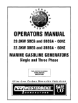
MARINE DIESEL GENERATORS
Single and Three Phase
20.0 KW BEDA 60 Hz 16.0 KW BEDA 50 Hz
25.0 KW BED 60 Hz 20.0 KW BED 50 Hz
32.0 KW BEDA 60 Hz 25.0 KW BEDA 50 Hz
PUBLICATION NO. 039685
4th Edition/August 1998
''CY WESI'ERBEKE
WESTERBEKE CORPORATION · AVON INDUSTRIAL PARK
AVON, MA 02322 • TEL (508) 588-7700 • FAX: (508) 559-9323
N AMIA M~m«r NalwlUll Mluine Manu/acwN!f"S As.rociation
SAFETY INSTRUCTIONS
INTRODUCTION
PREVENT BURNS - FIRE
Read this safety manual carefully. Most accidents are
caused by failure UJ follow fumiJJmenlill rules and precautions. Knaw when dangerous conditions exist and /O.ke the
necessary precautions UJ protect yourself, your per.;onne~
and your machinery.
The following safety instructions are in compliance wah
the American Boat and Yacht Council (ABYC) s/O.miJJrds.
I
•
A WARNING: Fire can cause injury
01 death!
Prevent flash fires. Do not smoke or permit flames or
sparks to occur near the carburetor, fuel line, filter, fuel
pump, or other potential sources of spilled fuel or fuel
V3JX>rs. Use a suitable container to catch all fuel when
removing the fuel line, carburetor, or fuel filters.
PREVENT ELECTRIC SHOCK
•
A WARNING: Do not touch AC electrical connections
while engine is running, or wilen connected to shore
POWel. Lethal roltage is present at these connections!
•
Do not operate wi th a Coast Guard Approved flame
arrester removed. Backfire can cause severe injury or
death.
•
Do not operate with the air cleaner/silencer removed.
Backfire can cause severe injury or death.
•
Do not smoke or pennit flames or sparks to
the fuel system. Keep the companment and
engine/generator clean and free of debris to
chances of fire. Wipe up all spilled fuel and
Do not operate this machinery without electrical
enclosures and covers in place.
•
Shut off electrical power before accessing electrical
equipment.
•
•
Use insulated mats whenever working on electrical
PREVENT BURNS - EXPLOSION
equipment.
•
Make sure your clothing and skin are dry, not damp
(panicularly shoes) when handling electrical equipment.
•
Remove wristwatch and all jewelry when working on
electrical equipment.
•
•
hatches closed when fueling. Open and ventilate cabin
circuits, except through a ship-Io-shore double throw
transfer switch. Damage to vessel 's AC generator may
after fueling. Check below for fumes/vapor before running the blower. Run the blower for four minutes before
starting your engine.
Electrical shock results from handling a c harged capacitor. Discharge capacitor by shoning terminals together.
•
All fuel vapors are highly explosive. Use extreme care
when handling and storing fuels. Store fuel in a well-ven-
tilated area away from spark-producing equipment and
out of the reach of children.
• Do not fill the fuel tank(s) while the engine is running.
• Shut off the fuel service valve at the engine when servicing the fuel system. Take care in catching any fuel that
might spill. DO NOT allow any smoking, open flames, or
other sources of fire near the fuel system or engine when
servicing. Ensure proper ventilation exists when servicing
the fuel system.
exhaust system components. A running engine gets
rery hot!
Always check the engine coolant level at the coolant
recovery tank.
• Do not alter or modify the fuel system.
A WARNING: Steam can cause injury 01 death!
• Be sure all fuel supplies have a positive shutoff valve.
•
•
Follow re-fueling safety instructions. Keep the vessel 's
Do not connect utility shore power to vessel's AC
A WARNING: 00 not touch hot engine parts or
I
diesel fuel will burn.
injury or death!
PREVENT BURNS - HOT ENGINE
•
minimize the
engine oil.
A WARNING: Explosions from fuel rapofS can cause
result if this procedure is not followed.
•
Be aware -
occur near
the
In case of an engine overheat, allow the engine to cool
before touching the engine or checking the coolant.
,.y-
Be certain fuel line fittings are adequately tightened and
free of leaks.
• Make sure a fire extinguisher is installed nearby and is
properly maintained. Be familiar with its proper use.
Extinguishers rated ABC by the NFPA are appropriate
for all applications encountered in this environment.
WES1ERBEKE
Engines & Generators
SAFETY INSTRUCTIONS
ACCIDENTAL STARTING
A
TOXIC EXHAUST GASES
WARNING: Accidemal starting can cause injury
A WARNING: carbon monoxide (CO) is a deadly gas!
or death!
•
Disconnect the battery cables before servicing the engine/
generator. Remove the negative lead first and reconnect
it last.
•
Make certain all personnel are clear of the engine before
starting.
•
Make certain all covers, guards, and hatches are reinstalled before starting the engine.
BATTERY EXPLOSION
A
WARNING: Battery explosion can cause injury
•
Ensure that the exhaust system is adequate to expel gases
discharged from the engine. Check the exhaust system
regularly for leaks and make sure the exhaust manifolds
are securely attached and no warping exists. Pay close
attention to the manifold, water injection elbow, and
exhaust pipe nipple.
•
Be sure the unit and its surroundings are well ventilated.
•
In addition to routine inspection of the exhaust system,
install a carbon monoxide detector. Consult your boat
builder or dealer for installation of approved detectors.
•
For additional information refer to ABYC T-22 (educational info rmation on Carbon Monoxide).
or death!
•
•
Do not smoke or allow an open flame near the battery
being serviced. Lead acid batteries emit hydrogen, a
highly explosive gas, which can be ignited by electrical
arcing or by lit tobacco prod ucts. Shut off all electrical
equipment in the vicinity to prevent electrical arcing during servicing.
A WARNING: carbon monoxide (CO) is an invisible
odorless gas. Inhalation produces flu-like symptoms,
nausea or death!
Never connect the negative (-) battery cable to the positive (+) connection tenninal of the starter solenoid. Do
not test the battery condition by shorting the tenninals
together. Sparks could ignite battery gases or fuel vapors.
Ventilate any compartment containi ng batteries to prevent
accu mulation of explosive gases. To avoid sparks, do not
disturb the battery charger connections while the battery
is being charged.
•
Avoid contacting the terminals with tools, etc., to prevent
bums or sparks that could cause an explosion . Remove
wristwatch, rings, and any other jewelry before handling
the battery.
•
Always tum the battery charger off before disconnecting
the battery connections. Remove the negative lead first
and reconnect it last when servicing the battery.
•
Do not use copper tubing in diesel exhaust systems.
Diesel fumes can rapidly destroy copper tubing in exhaust
systems. Exhaust sulfur causes rapid deterioration of copper tubing resulting in exhaust/water leakage.
•
Do not install exhaust outlet where exhaust can be drawn
through portholes, vents, or air conditioners. If the engine
exhaust discharge outlet is near the waterline, water could
enter the exhaust discharge outlet and close or restrict the
flow of exhaust. Avoid overloading the craft.
•
A1though diesel engine exhaust gases are not as toxic as
exhaust fumes from gasoline engines, carbon monoxide
gas is present in diesel exhaust fumes. Some of the symptoms or signs of carbon monoxide inhaJation or poisoning
are:
Vomiti ng
Dizzi ness
BATTERY ACID
Throbbi ng in temples
Muscular twitching
A WARNING: Sulfuric acid in batteries can cause
Intense headache
severe injury or death!
Weakness and sleepiness
AVOID MOVING PARTS
• Wben servicing the battery or checking the electrolyte
level, wear rubber gloves, a rubber apron , and eye protection. Batteries contain sulfuric acid which is destructive. If
it comes in contact with your skin, wash it off at once
with water. Acid may splash on the skin or into the eyes
inadvenently when removing electrolyte caps.
A WARNING: Rotating parts can cause injury
or death!
•
Do not service the engine while it is running. If a situation arises in which it is absolutely necessary to make
operating adj ustments, use extreme care to avoid touching moving parts and hot exhaust system components.
Engines & Generators
ii
SAFETY INSTRUCTIONS
•
•
•
•
ABYC, NFPA AND USCG PUBUCATIONS FOR
INSTAWNG DIESEL ENGINES
Do not wear loose clothing or jewelry when servicing
equipment; avoid wearing loose jackets, shirts, sleeves,
rings, necklaces or bracelets that could be caught in
moving parts.
Read the following ABYC, NFPA and USCG publications
for safety codes and standards. Follow their recommendations when installing your UNIVERSAL engine
Make sure all anaching hardware is properly tightened.
Keep protective shields and guards in their respective
places at all times.
ABYC (American Boat and Yacht Council)
"Safety Standards for Small Craft"
Do not check fluid levels or the drive belt's tension while
the engine is operating.
Order From:
ABYC
3069 Solomon's Island Rd.
Edgewater, MD 21037
Stay clear of the drive shaft and the transmission coupling when the engi ne is running; hair and clothing can
easily be caught in these rotating parts.
NFPA (National Fire Protection Association)
"Fire Protection Standard for Motor Craft"
HAZARDOUS NOISE
A
Order From:
WARNING: High noise levels can cause hearing
NFPA
1 Batterymarch Park
P.O. Box 9101
Quincy, MA 02269-9101
loss!
•
Never operate an engine without its muffler installed.
•
Do not run an engine with the air intake (silencer)
removed.
•
Do not run engines for long periods with their enclosures
open.
USCG (United States Coast Guard)
"USCG 33CFR183"
Order From:
U.S. Government Printing Office
Washington, D.C. 20404
A
WARNING: 00 not wortc on machinery wilen you are
mentally or physically incapacitated by fatigue!
OPERATORS MANUAL
Many of the preceding safety tips and warnings are repeated
in your Operators Manual along with other cautions and
notes to highlight critical information. Read your manual
carefully, maintain your equipment, and follow all safety
procedures.
ENGINE INSTALLATIONS
Preparations to install an engine should begin with a thorough examination of the American Boat and Yacht Council 's
(AByq standards. These standards are a combination of
sources including the USCG and the NFPA.
Sections of the ABYC standards of particular interest are:
H-2 Ventilation
P-l Exhaust systems
P-4 Inboard engines
E-9 DC Electrical systems
All installations must comply with the Federal Code of
Regulations (FCR).
I~IWESTERBEKE
r
Engines & Generators
iii
INSTALLATION
When installing WESTERBEKE engines and generators it is important that strict
anention be paid to the foHowing infonnation:
CODES AND REGULATIONS
Strict federal regulations, ABYC guidelines, and safety codes must be complied with
when installing engines and generators in a marine environment.
SIPHoN·BREAK
For installations where the exhaust manifold/water injected exhaust elbow is close lO
or below the vessel's waterline, provisions must be made to install a siphon-break in
the raw water supply hose to the exhaust elbow. This hose must be looped a minimum
of 18" above the vessel's waterline. Failure to use a siphon-break when the exhaust
manifold injection port is at or beww the load waterline will result in raw water
damage to the engine and possible flooding of the boat.
EXHAUST SYSTEM
The exhaust hose must be certified for marine use. The system must be designed to
prevent water from entering the exhaust under any sea conditions and at any angle
of the vessels hull.
A detailed 40 page Marine Installation Manual covering gasoline and
diesel, engines and generators, is available from your WESTERBEKE
dealer.
Engines & Generators
iv
OPERATORS MANUAL
WESTERBEKE
MARINE DIESEL GENERATORS
Single and Three Phase
20.0 KW BEDA 60 Hz 16.0 KW BEDA 50 Hz
25.0 KW BED 60 Hz 20.0 KW BED 50 Hz
32.0 KW BEDA 60 Hz 25.0 KW BEDA 50 Hz
PUBLICATION NO. 039685
4th Edition/August 1998
''''.7 WESJ'ERBEKE
WESTERBEKE CORPORATION· AVON INDUSTRIAL PARK
---
AVON, MA 02322 • TEL: (508) 588-7700 • FAX: (508) 559-9323
A:,.MMA Member Nalional Marine Manufacturers Association
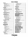
TABLE OF CONTENTS
Introduction .......................................................................2
Fuel Filters ................................................................. 17
Changing the Fuel Filters .................................... 17
Feed Pump Strainer (32 KW) .................................... 17
Bleeding the Fuel System ......................................... .18
Fuel Pressure Gauge ................................................... 18
Fuel Additives ............................................................ 18
Spares ......................................................................... 18
Engine Oil Change ..........................................................19
Engine Oil Change ..................................................... 19
Oil Pressure ................................................................ 19
Remote Oil Filter ............................................................20
Installation .................................................................. 20
DC Electrical System .....................................................21
Engine 12 Volt DC Control Circuit.. .......................... 21
Battery Specification .................................................. 21
Battery Care ............................................................... 21
Glow Plugs ................................................................. 21
DC Electrical System/Alternator ..................................22
Troubleshooting .......................................................... 22
Testing the Alternator ................................................. 22
DC Electrical System Wiring Diagram ........................24
DC Electrical System Wiring Schematic ....................25
Remote Start/Stop Panel ...............................................25
Electronic Governor .......................................................26
Troubleshooting the Electronic Governor ................. .27
Engine Adjustments .......................................................28
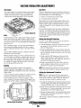
Valve Clearance Adjustment ..................................... .28
Drive Belt Adjustment ............................................... 28
Torquing Cylinder Head Bolts ................................... 29
Engine Compression .................................................. 29
Testing the Fuel Injectors ........................................... 29
Inspecting the Spray Pattern ...................................... 30
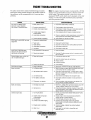
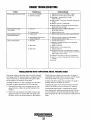
Engine Troubleshooting .................................................31
Troubleshooting Water Temp. and Oil Gauges ......... .32
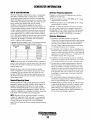
Generator Information ...................................................33
Use of Electric Motors .............................................. .33
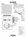
The BE Generator ...........................................................34
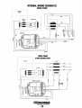
Internal Wiring Schematics ........................................ 35
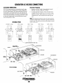
Generator AC Voltage Connections ........................... .36
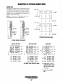
BE Three Phase (Six Wire) ........................................ 37
BE Three Phase (Twelve Wire) ................................. .37
Voltage Regulator Adjustments ...................................38
BE Troubleshooting ................................................... 39
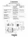
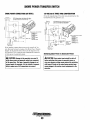
Shore Power Transfer Switch .......................................40
Lay-Up and Recommissioning ......................................41
Specifications 20 KW BEDA Generator ..................... .43
Specifications 25 KW BED Generator ........................ .45
Specifications 32 KW BEDA Generator ..................... .47
Warranty Procedures .................................................... 2
Customer Identification Card ...................................... .2
Product Software .......................................................... 2
Notes, Cautions and Warnings ..................................... 2
Serial Number Location ............................................... 3
Understanding the Diesel Engine ................................. 3
Ordering Parts .............................................................. 3
Spares and Accessories ................................................ 3
Control Panels ..................................................................4
Main Panel .................................................................. .4
Remote Panel .............................................................. .4
Diesel Fuel, Engine Oil and Engine Coolant ...............5
Diesel Fuel ...................................................................5
Care Of The Fuel Supply ............................................. 5
Engine Oil ....................................................................5
Oil Pressure .......................................................•..........5
Engine Coolant .............................................................5
Coolant Recovery Tank ................................................ 5
Preparations for Initial Start-Up ...................................6
Prestart Inspection ........................................................ 6
Generator Voltage .........................................................6
StartingtStopping Procedure ..........................................7
The Starting System ..................................................... 7
Remote Starting Procedure .......................................... 7
Starting Under Cold Conditions ................................... 8
Stopping Procedure ...................................................... 8
Remote Stopping Procedure ......................................... 8
Safety Shut down Switches .......................................... 8
High Exhaust Temperature Switch ....................... 8
High Water Temperature Switch ........................... 8
Low Oil Pressure Switch ...................................... 8
Engine Circuit Breaker ......................................... 8
Generator Break-In Procedure .......................................9
Description ................................................................... 9
After Start-up ............................................................... 9
Check List .................................................................... 9
Generator Adjustments ................................................. 9
The Daily Routine ...........................................................10
Check List .................................................................. 10
Start the Generator ..................................................... 10
Maintenance Schedule ..................................................11
Engine Cooling Circuit. ..................................................13
Description ................................................................. 13
Fresh Water Circuit .................................................... 14
Coolant Recovery Tank ....................................... 14
Changing Coolan!. ...................................................... 14
To Refill the Coolant... ........................................ 14
Thermostat .................................................................. 14
To Replace The Thermostat.. .............................. 14
Raw Water Cooling Circuit.. ...................................... 14
Raw Water Pump ................................................ 14
Changing the Raw Water Pump Impeller ........... 14
Heat Exchanger .......................................................... 14
Zinc Anode .......................................................... 14
Heat Exchanger Service ...................................... 14
Fuel System .....................................................................16
Diesel Fuel ................................................................. 16
Fuel Water Separator .................................................. 16
Fuel Lift Pumps .......................................................... 16
Fuel Injection Pump ................................................... 16
-.Y'
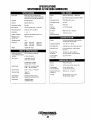
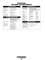
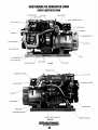
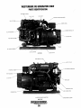
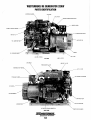
Photo Identification 20 KW ..........................................49
Photo Identification 25 KW ..........................................50
Photo Identification 32 KW ..........................................51
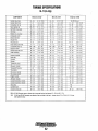
Torque Specifications .....................................................52
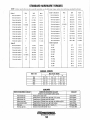
Standard Hardware Torques .........................................53
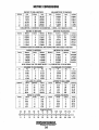
Metric Conversions ........................................................54
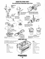
Suggested Spare Parts ..................................................55
WESTERBEKE
Engines & Generators
1
INTRODUCTION
This WESTERBEKE Diesel Generator is a product of
WESTERBEKE's long years of experience and advanced
technology. We take great pride in the superior durability and
dependable performance of our engines and generators.
Thank you for selecting WESTERBEKE.
In order to get the full use and benefit from your generator it
is important that you operate and maintain it correctly. This
manual is designed to help you do this. Please read this
manual carefully and observe all the safety precautions
throughout. Should your generator require servicing, contact
your nearest WESTERBEKE dealer for assistance.
This is your operators manual. A parts catalog is also
provided and a technical manual is available from your
WESTERBEKE dealer. If you are planning to install this
equipment contact your WESTERBEKE dealer for
WESTERBEKE'S installation manual.
PRODUCT SOFTWARE
Product software, (tech data, parts lists, manuals,
brochures and catalogs), provided from sources other than
WESTERBEKE are not within WESTERBEKE's control.
WESTERBEKE CANNOT BE RESPONSIBLE FOR THE
CONTENT OF SUCH SOFTWARE, MAKES NO WARRANTIES OR REPRESENTATIONS WITH RESPECT
THERETO, INCLUDING ACCURACY, TIMELINESS OR
COMPLETENESS THEREOF AND WILL IN NO EVENT
BE LIABLE FOR ANY TYPE OF DAMAGE OR INJURY
INCURRED IN CONNECTION WITH ORARISING OUT
OF THE FURNISHING OR USE OF SUCH SOFTWARE.
WESTERBEKE customers should also keep in mind the
time span between printings of WESTERBEKE product
software and the unavoidable existence of earlier
WESTERBEKE manuals. In summation, product software
provided with WESTERBEKE products, whether from
WESTERBEKE or other suppliers, must not and cannot
be relied upon exclusively as the definitive authority on
WARRANTY PROCEDURES
Your WESTERBEKE Warranty is included in a separate
folder. If, after 60 days of submitting the Warranty Registry
the respective product. ]t not only makes good sense
form you have not received a customer identification card
registering your warranty, please contact the factory in
writing with model iDfomation, including the unit's serial
number and commission date.
but is imperative that appropriate representatives of
WESTERBEKE or the supplier in question be consulted
to determine the accuracy and currentness of the
product software being consulted by the customer.
Customer Identification Card
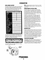
NOTES, CAUTIONS AND WARNINGS
As this manual takes you through the operating procedures,
maintenance schedules, and troubleshooting of your marine
engine, critical infonnation will be highlighted by NOTES,
CAUTIONS, and WARNINGS. An explanation follows:
I~I WESTERBEKE
1
Customer Identification
MR. GENERATOR OWNER
MAIN STREET
HOMETOWN, USA
Model 32 BEDA
Ser. #UOOOO-D702
Expires 4/4/98
NOTE: An operating procedure essential to note.
A CAUTION: Procedures, which if not strictly
observed, can result in the damage or destruction of
your engine.
A WARNING: Procedures, which if not properly fol·
The WESTERBEKE serial number is an alphanumeric
number that can assist in determining the date of manufacture of your WESTERBEKE engine or generator. The manu-
lowed, can result in personal injury or loss of life.
facturer's date code is placed at the end of the engine serial
number and consists of a character followed by three
numbers. The character indicates the decade. (A = 1960s,
B =1970s, C = 1980s, D = 1990s, the first number represents
the year in the decade and the second and third numbers the
month of manufacture.
, . . WESTERBEKE
Engines & Generators
2
INTRODUCTION
NOTE:A carbon monoxide warning decal has been provided
SERIAL NUMBER LOCATION
by WESTERBEKE. Affix this decal in a visible position in the
The engine and generator serial numbers and model numbers
are located on a decal on the generator housing. Take the
time to enter the information on the blank decal provided
below as this will provide a quick reference when seeking
technical information and/or ordering repair parts.
SPECIFICATION
MODEL _______ _
RPM __________ _
I
engine room
UNDERSTANDING THE DIESEL ENGINE
The diesel engine closely resembles the gasoline engine,
since the mechanism is essentially the same. The cylinders
are arranged above a closed crankcase; the crankshaft is of
the same general type as that of a gasoline engine; and the
diesel engine has the same types of valves, camshaft, pistons,
connecting rods and lubricating system.
60 HZ.
Therefore, to a great extent, a diesel engine requires the
same preventive maintenance as a gasoline engine. The
most important factors are proper ventilation and proper
maintenance of the fuel, lubricating and cooling systems.
Replacement of fuel and lubricating filter elements at the
time periods specified is a must, and frequent checking for
contamination (that is, water, sediment, etc.) in the fuel
system is also essential. Another important factor is the use
of the same brand of high detergent diesel lubrication oil
designed specifically for diesel engines.
KW ___________ _
KVA __________ _
VOLTS ________ _
AMPS ________ _
ENG. HP ______ _
ENG. SER. NO.
GEN. SER. NO.
PF/PHASE ___ _
WIRES________ _
RATING _______ _
The diesel engine does differ from the gasoline engine,
however, in its method of handling and firing of fuel. The
carburetor and ignition systems are done away with and in
their place is a single component - the fuel injection pump which performs the function of both.
ORDERING PARTS
INSUL CLASS __
TEMP. RISE ___ _
BAlTERY _____ _
C.I.D. _________ _
Whenever replacement parts are needed, always provide the
generator model number, engine serial number, and generator
serial number as they appear on the silver and black name
plate located on the generator end. You must provide us with
this information so we may properly identify your generator
set. In addition, include a complete part description and part
number for each part needed (see the separately furnished
Parts List). Also insist upon WESTERBEKE packaged parts
because will fit or generic parts are frequently not made to
the same specifications as original equipment.
The engine serial number can also be found stamped into the
engine block just above the injection pump. The generator
serial number is stamped into the generator housing on the
fiat surface on the left side of the generator.
SPARES AND ACCESSORIES
Certain spares will be needed to support and maintain your
WESTERBEKE generator. Your local WESTERBEKE
dealer will assist you in preparing an inventory of spare parts.
See the SPARE PARTS page in this manual. For Engine and
Generator Accessories, see the ACCESSORIES brochure.
An identification plate on the engine manifold also displays
the engine model and serial number.
ENGINE
SERIAL
NUMBER
Engines & Generators
3
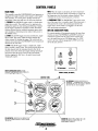
CONTROL PANELS
NOTE: When the engine is shut down, the water temperature
gauge and the oil pressure gauge will continue to register the
last temperature and oil pressure readings displayed. They
will return to zero once electrical power is restored.
MAIN PANEL
This manually-controlled WESTERBEKE diesel generator is
equipped with toggle switches on the engine's control panel
and, optionally. at a remote panel. All three switches arc
momentary contact type and serve the following functions:
4. EMERGENCY STOP: The EMERGENCY stop switch at the
rear of the control hox is normally closed. When depressed, it
will open the DC circuit to the control panel and shut the
engine down. As the switch is not toggled it can be used
when performing maintenance.
1. PREHEAT: The PREHEAT toggle switch is a double-pole,
single-throw switch. The switch serves two purposes: preheating the engine for easy starting and defeating or bypa<;sing the engine's protective oil pressure switch. The defeat
function activates the fuel solenoid, instrument power, alternator excitation, electronic governor and provides power to
the START switch.
REMOTE START/STOP PANEL
For remote operation of the generator system, the same three
switches are used. The PREHEAT and START switches arc
connected in parallel with the gauge panel's switches and
serve the same functions as in the gauge pane!. The STOP
switch is in series with the gauge panel's STOP switch and
serves the same function.
2. START: The START toggle switch is a douhle-pole, singlethrow switch. The switch, when activated, energizes the
starter solenoid for starting the engine. This switch will flot
operate electrically unless the PREH EAT switch is depressed
and held at the same time.
3. STOP: The STOP toggle switch is a single-pole, singlethrow, normally closed switch. This switch provides power to
the fuel solenoid, and the instrument cluster, after the oil
pressure switch has closed upon engine starting. Opening of
this switch opens the power circuit to the fuel solenoid,
thereby stopping the fuel flow to the injection pump and
stopping the engine.
,
0
STOP
~
@
RELEASE
STARTER
START
MUST~
~PRESS
PRESS
FIRST
•
C'W,IMI'
0
WATER TEMPERATURE GAUGE: ENGINE
COOLANT TEMPERATURE. SHOULD INDICATE
175' TO 195'F (80' TO 91 'C)
2ND
GENERATOR
0
REMOTE PANEL (OPTIONAL)
CONTROL PANEL
4
o
OIL PRESSURE: ENGINE LUBRICATION OIL
PRESSURE - THE NEEDLE WILL FLUCTUATE
DEPENDING ON LOAD. BUT SHOULD INDICATE
50 TO 57 PSI (35 TO 4.5 KG/CM)
o
DC VOLTMETER: INDICATES THE AMOUNT THE
BATIERY IS BEING CHARGED. SHOULD SHOW
13V TO 14V
HOURMETER: REGISTERS ELAPSED TIME. AND
SHOULD BE USED AS A GUIDE FOR THE
MAINTENANCE SCHEDULE.
-.,.yo
WESTERBEKE
Engines & Generators
4
DIESEL FUEL, ENGINE OIL AND ENGINE COOLANT
DIESEL FUEL
ENGINE COOLANT
Use fuel that meets the requirements or specification of Class
2-D (ASTM), and has a cetane rating of #45 or hetter.
WESTERBEKE recommends a mixture of 50% antifreeze
and 50% distilled water. Distilled water is free from the
chemicals that can corrode internal engine surfaces.
Care Of The Fuel Supply
The antifreeze performs double duty. It allows the engine to
run at proper temperatures by transferring heat away from
the engine to the coolant, and lubricates and protects the
cooling circuit from rust and corrosion. Look for a good
quality antifreeze that contains Supplemental Cooling
Additives (SeAs) that keep the antifreeze chemically balanced, crucial to long term protection.
Use only clean diesel fuel! The clearance of the components
in your fuel injection pump is very critical; invisible dirt particles which might pass through the filter can damage these
finely finished parts. It is important to buy clean fuel, and
keep it clean. The best fuel can be rendered unsatisfactory by
careless handling or improper storage facilities. To assure
that the fuel going into the tank for your engine's daily use is
clean and pure, the following practice is advisable:
The distilled water and antifreeze should be premixed before
being poured into the cooling circuit.
Purchase a well-known brand of fuel.
NOTE: Look for the new environmentally-friendly long lasting
Install and regularly service a good, visual-type filter/water
separator between the fuel tank and the engine. The Raycor
500 FG or 900 FG are good examples of sueh filters.
antifreeze that is now available.
Antifreeze mixtures will protect against an unexpected freeze
and they are beneficial to the engine's cooling system. They
retard rust and add to the life of the circulating pump seal.
ENGINE OIL
Use a heavy duty engine oil with an API classification of CF
or CG-4 or better. Change the engine oil after an initial 50
hours of break-in operation, and every 100 hours of operation
thereafter. For recommended oil viscosity, sec the following
chart·
Operating Temperature
Oil Viscosity
Above 68°F (20°C)
SAE 30. 1OW·30 or 15W-40
41°-68°F (5·20°C)
SAE 20. 1OW·30 or 15W-40
Below 4n (SoC)
SAE 1OW·30 or 15W·40
ANTIFREEZE PROTECTION
Antifreeze Concentration
Freezing Temperature
23%
30%
35%
50%
WF
(-WOC)
Coolant Recovery Tank
A coolant recovery tank kit is supplied with each
WESTERBEKE diesel engine. The purpose of this recovery
tank is to allow for engine coolant expansion and contraction
during engine operation, without the loss of coolant and
without introducing air into the cooling system. This kit is
provided and must be installed before operating the engine.
A
CAUTION: 00 not allow two or more brands of
engine oil to mix. Each brand contains its own additives;
additives of different brands could react in the mixture
to produce properties hannful to your engine.
NOTE: This tank, with its short run of plastic hose, must he
located at or above the engine:5 manifold and he easily
accessible for checking and adding fluid.
Oil Pressure
The engine's oil pressure, during operation, is indicated
by the oil pressure gauge on the instrument panel. During
normal operation, the oil pressure will range between 35 and
55 psi.
NOTE: A newly slarted, cold engine can have an oil pressure
reading upwards of 60 psi. A warmed engine can have an oil
pressure reading as low as 25 psi. These readings will vary
depending upon the temperature of the engine and the load
placed on the generator.
Engines & Generators
5
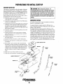
PREPARATIONS FOR INITIAL START-UP
PRESTART INSPECTION
A CAUTION: When starting the generator, it is
This section of the manual provides the operator with prepa~
ration, initial starting. break-in, starting (warm or cold) and
stopping procedures. Follow the procedures as presented for
the conditions indicated and your WESTERBEKE generator
set will give reliable performance and long service life.
recommended that all AC loads, especially large motors,
be switched OFF until the engine has come up to speed
and, in cold climates, starts to warm up. This precaution
will prevent damage caused by unanticipated operation
of the AC machinery and will prevent a cold engine from
stalling.
Before starting your generator set for the first time or after a
prolonged layoff, check the following items:
o
o
o
o
o
o
o
o
o
o
Check the engine oil level. Add oil to maintain the level
at the high mark on the dipstick.
GENERATOR VOLTAGE
Check the fuel supply and examine the fuel filter/separator bowls for contaminants.
The speed of the generator engine is adjusted at the factory,
however, it is advisable to verify.
Check the DC electrical system. Inspect wire connections
and battery cable connections. Make certain the (+) battery cable is connected to the starter solenoid and the
negative (-) cable is connected to the engine ground stud
(this location is tagged).
10 supply 60 hertz, the speed should be 1800 rpm at noload, and should not fall below 1800 rpm by more than .005
percent .3 Hz at full-load.
To supply 50 hertz, the speed should be 1500 rpm al fullload. Generator voltage should build to its rated value within
5 seconds after rated speed is attained. Record or observe the
voltage of the generator at no-load and at full-load (hot). The
voltages are easily adjusted to optimum values no-load and
full-load (refer to VOLTAGE ADJUSTMENT in this manual).
If possible, apply actual service load or test load of the same
power factor as the load to he used in service. If the voltage
cannot be adjusted to suitable values and a fault seems evident, contact your authorized WESTERBEKE service dealer.
Check the coolant level in both the plastic recovery tank
and at the manifold.
Visually examine the unit. Look for loose or missing
parts, disconnected wires, unattached hoses, and check
threaded connections.
Check load leads for correct connection as specified in
the wiring diagrams.
Examine air inlet and outlet for air flow obstructions.
Be sure no other generator or utility power is connected
to load lines.
""
Be sure that in power systems with a neutral line that
the neutral is properly grounded (or ungrounded) as thc
system requires, and that the generator neutral is properly
connected to the load neutral. In single phase and some
3-phase systems an incomplete or open neutral can supply the wrong line-to-neutral voltage on unbalanced
loads.
COOLANT RECOVERY TANK
DIPSTICK
20 KW
Make sure the mounting installation is secure.
D Make sure that the generator is properly grounded.
MANtFOLD PRESSURE CAP
DIPSTICK
32 KW
I
ENGINE OIL FILL
~j
iT;
StOE OIL FtLl ........
32KW
........
I
-..v WESTERBEKE
Engines & Generators
6
DtPSTtCK
25 KW
STARTING/STOPPING PROCEDURE
Should the engine not start when the START switch is
depressed for 10 to 20 seconds, release both switches and
wait 30 seconds; repeat the procedure above and preheat
longer. Never run the starter for more than 30 seconds.
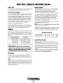
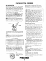
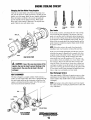
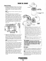
THE STARTING SYSTEM
Westerbeke diesel generators usc electric starters assisted by
glow plugs for both normal and cold weather starting. The
illustration below shows a cross-sectional view of one cylinder. The glow plug is located in the combustion chamber so
that its tip is in the injector nozzle's spray path. When the
glow plug is energized by the PREHEAT button, the plug
glows red at the tip and assists in igniting the fuel. The result
is a rapid start with less wear on the starter.
A
CAUTION: Prolonged cranking intervals without the
engine starting can result in the engine exhaust system
filling with raw water. This may happen because the
pump is pumping raw water through the raw water cooling system during cranking. This raw water can enter the
engine's cylinders by way of the exhaust manifold once
the exhaust system fills. Prevent this from happening by
closing the raw water supply through-hull shut·off,
draining the exhaust muffler, and correcting the cause
of the excessive engine cranking. Engine damage result·
ing from raw water entry is not a warrantable issue; the
owner/operator should keep this in mind.
This system is common to WESTERBEKE diesels. The start
circuitry is designed so that the PREHEAT button must be
depressed for the time specified in the preheat chart. Then,
while keeping the PREHEAT button engaged, the START
button is depressed to crank the engine.
NOTE: The START switch will not energize unless the PREHEAT switch is depressed. Depressing the PREHEAT switch
activates the glow plugs in the cylinder head so use the PREHEAT i11lermittentiy to avoid overheating the glow plugs.
Remote Starting Procedure
GLOW PLUG
The remote start pane! is the same as the engine-mounted
start panel except that it has a green LED light and no
gauges. When starting at a remote location, the green LED
lights when the generator is running at approximately nOO
rpm. This indicates when the START switch can he rcleased
since the starting of the generator may not bc audible.
A. When the PREHEAT switch is depressed at the remote
startfstop panel the LED light will illuminate. When the
START switch is depressed and the starter cranks the
engine this LED light will dim. When the engine starts
the LED light will brighten signaling to release the
START switch. Continue to hold the PREHEAT
depressed for a few seconds to allow oil pressure to build
up which closes the oil pressure safety switch that is in
the series path for 12V B+ to the fuel run solenoid. The
green LED will remain brightly illuminatcd while the
engine is running.
An air intake heater is used in place of glow plugs on the
32 KW generator. The preheat sequence described is the
same.
PREHEAT: Depress the PREHEAT switch. The voltmeter and
pane! lights, gauges and meters will be activated. The PREHEAT switch should he depressed in accordance with the
following chart:
Temperature/Preheat
Atmospheric Temperature
D
+41°F(+5 C)
or higher
+41°F(+5°C) to 23°F (-5°C)
B. After the generator is started and the START switch is
released, the generator's starter will not crank unless thc
PREHEAT switch is operated first because this switch
supplies voltage to the START switch.
Preheating Time
Approx. 10 seconds
Approx. 15 seconds
+23°F(-5°C) or lower
Approx. 20 seconds
Limit of continuous use
30 seconds before cranking
Once the engine starts, check the engine's instruments for
proper oil pressure and battery charging voltage. Apply a
light load to the generator and allow the engine's operating
temperature to come up to 140-150' (60-66" C) before
applying heavy loads.
START: While still depressing the PREHEAT switch, depress
the START switch. This will engage the starter solenoid.
Upon engine starting, release the START switch. Do not
release the PREHEAT switch until the oil pressure reaches
15 psi. Then as long as the high water temperature and low
oil pressure prOlective circuits do not activate, the engine will
remain energized and continue to run.
NOTE: Some unstable running may occur ill a cold ellgille.
Depressing the PREHEAT switch/or 10-J5 second intervals
will help stabilize the engine rpm until the operating
temperature reaches 140 - 150 F and a load is applied!O
the engine.
0
NOTE: When starting:
A voltage drop will occur
when the preheat switch
is depressed.
STARTING UNDER COLD CONDITIONS
Make sure the lubricating oil confonns with the ratings for
the prevailing temperature. Check the table in the ENGINE
OIL section in this manual.
-..v WESTERBEKE
Engines & Generators
7
STARTING/STOPPING PROCEDURE
STARTING UNDER COLD CONDITIONS
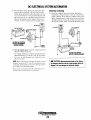
High Water Temperature Switch
Make sure the lubricating oil conforms with the ratings for
the prevailing temperature. Check the table in the ENGINE
OIL section in this manual.
A high water temperature switch is located on the thermostat
housing. Normally dosed, this switch, should the fresh water
coolant's operating temperature reach approximately 210 0 P
(99°C), will open and interrupt the DC voltage to the fuel
solenoid on the injection pump, thereby shutting off the
engine. This switch resets at 195°F (ImOC).
The battery should be fully charged to minimize voltage
drop.
Use a sufficient amount of preheat to aid in starting. Sec the
Temperature/Preheat chart on the previous page.
THERMOSTAT
STOPPING PROCEDURE
1. Remove the AC electrical load from the generator and
allow the generator to run for three to five minutes to sta~
bilize its operating temperatures.
2. Depress the STOP switch and hold it until the generator
is completely stopped.
3.
Now release the STOP switch.
Remote Stopping Procedure
To stop the generator, depress the STOP switch
which opens the normally closed \1+ path for
voltage to the engine's run circuit. The STOP
switch must be held open until the generator
HIGH WATER
TEMPERATURE SWITCH
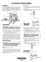
Low Oil Pressure Switch
comes to a complete stop.
TEMPERATURE
SWITCH
A low oil pressure shutdown switch is located off the
engine's oil gallery. Normally open in a static state, this
switch's sensor monitors the engine's oil pressure. Should the
engine's oil pressure fall to 5~ 10 psi, this switch will open
interrupting the DC voltage to the fuel solenoid Oil the injec~
tion pump, thereby shutting otf the engine.
HOTE: The generator is stopped when the electric
solelloid mounted Oil the injection pump is
de-energized shutting off the flow affuel (Models 20 KW
and 25 KW). The 32 KW Generator is
shutdown hy all electric fuel solenoid that is
auached 10 a lever 011 the fuel injection pump.
SAFETY SHUTDOWN SWITCHES
The engine is protected by three automatic shut~
down switches. Should shutdown occur, do not
Oil
PRESSURE
SWITCH - - , , " ' .
attempt to restart without finding and correcting
the cause. Refer to the heading "Engine Stops"
in the TROUBLESHOOTING section of/his
manual. The following is a description of these
Oil PRESSURE
SENDER
automatic shutdown switches:
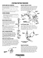
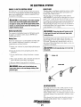
High Exhaust Temperature Switch
An exhaust temperature switch is located on the exhaust
elbow. Normally closed, this switch will open and interrupt
the DC voltage to the fuel solenoid on the injection pump
(shutting OFF the engine) should the switch's sensor indicate
an excessive exhaust temperature (an inadequate supply of
raw water causes high exhaust temperatures). This switch
opens at 260-270°F (127-132°C). This switch resets at
approximately 225°F (lOTC).
LOW OIL PRESSURE SWITCH
[20 KW SHOWN]
Engine Circuit Breaker
The generator's engine is protected by an engine mounted
manual reset circuit breaker (20 amps DC). Excessive current
draw or electrical overload anywhere in the instrument panel
wiring or engine wiring will cause the breaker to trip. In this
event most generators will shut down because the opened
breaker disconnects the fuel supply. If this should occur,
check and repair the source of the problem. After repairing
the fault, reset the breaker and restart the generator.
EXHAUST ELBOW
HIGH EXHAUST~>"'-~::.t
TEMPERATURE
SWITCH
"U. '.lV
"ti¥
WESTERBEKE
Engines & Generators
8
GENERATOR BREAK-IN PROCEDURE
DESCRIPTION
CHECK THE FOLLOWING
Although your engine has experienced a minimum of one
hour of tcst operations at the factory to make sure accurate
assembly procedures were followed and that the engine operated properly, a break-in time is required. The service life of
your engine is dependent upon how the engine is operated
and serviced during its initial hours of use.
D Monitor the control panel gauges.
o Check for leaks of fuel and engine oil.
D Check for abnormal noise such as knocking, friction,
vibration and blow-back sounds.
D Confirm exhaust smoke:
Breaking-in a new engine basically involves seating the piston fings to the cylinder walls. Excessive oil consumption
and smoky operation indicate that the cylinder walls arc
scored, which is caused by overloading the generator during
the break-in period.
When the engine is cold - White Smoke.
When the engine is warm - almost Smokeless.
When the engine is overloaded - some Black Smoke.
To protect against unintentional overloading of the generator,
the generator's output leads should be routed through a circuit breaker that is rated at the rated output of the generator.
Your new engine requires approximately 50 hours of initial
conditioning operation to break in each moving part in order
to maximize the performance and service life of the engine.
Perform this conditioning carefully, keeping in mind the
following:
NOTE: Be aware of motor starting loads and the high currelll
draw required for Slarling motors. This starting amperage
draw can be 3 to 5 limes normal running amperage. See
GENERATOR INFORMATION ill [his manual.
Start the engine according to the STARTING PROCEDURE
section. Run the engine while checking that all systems (raw
water pump, oil pressure, battery charging) are functioning.
GENERATOR ADJUSTMENTS
Once the generator has been placed in operation, there may
be adjustments required for engine speed (hertz) during the
engine's break-in period (first 50 hours) or after this period.
A no-load voltage adjustment may also be required in conjunction with the engine's speed adjustment. See
GENERATOR INFORMATION in this manual.
AFTER START-UP
Once the generator has been started, check for proper operation and then encourage a fast warm-up. Run the generator
hetween 20% and 60% of full-load for the first 10 hours.
A
CAUTION: Do not attempt to break-in your
generator by running without a load.
After the first 10 hours of the generator's operatIOn, the load
can be increased to the full-load rated output, then periodically vary the load.
Avoid overload at all times. An overload is signaled by
smoky exhaust with reduced output voltage and frequency.
Monitor the current being drawn from the generator and keep
it within the generator's rating. Since the generator operates
at 1800 rpm to produce 60 hertz (or at 1500 rpm to produce
50 Hertz), control of the generator's break-in is governed by
the current drawn from the generator.
...v WESTERBEKE
Engines & Generators
9
THE DAILY OPERATION
CHECK LIST
START THE GENERATOR
Follow this check list each day before starting your generator.
(See STARTING PROCEDURES nn previous pages).
Allow the engine to warm up for 5 to 1() minutes to reach an
operating temperature of 140" to 150"F (60"·66"C) before
applying AC loads. Apply loads systematically allowing the
generator to adjust to cach load before applying the next.
Check the gauges for proper oil pressure, operating temperature, and DC voltage.
o Record the hourmetcr reading in your log (engine hours
relate to the maintenance schedule.)
D Visually inspect the generator for fuel, oil, or water leaks.
o Check the oil level (dipstick).
o Check the coolant level in the coolant recovery tank.
o Check your diesel fuel supply.
NOTE: Some unstable rUllning may occur in a cold engine.
This conditioJl should lessen as normal operating temperature is reached and loads are applied.
D Look for clean fuel in the fuel/separator transparent bowl.
D Check for loose wires at the alternator.
A CAUTION: Do not operate the generator for long
o Check the starting batteries (weekly).
periods of time without a load being placed on the
D Check drive belts for wear and proper tension (weekly).
STOPPING THE GENERATOR
Remove the major AC loads from the generator one at a
time. Allow the generator to run for a few minutes to stabilize the operating temperature and depress the stop switch.
(Sec STOPPING PROCEDURES on previous pages.)
Engines & Generators
10
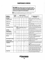
MAINTENANCE SCHEDULE
A WARNING: Never attempt to perform any service while the engine is
running. Wear the proper safety equipment such as goggles and gloves, and
use the correct tools for each job. Disconnect the battery terminals when
servicing any of the engine's DC electrical equipment.
NOTE: Many of the following maintenance jobs are simple but others are more
difficult and may require the expert know/edge of a service mechanic.
SCHEDULED
MAINTENANCE
CHECK
EACH
DAY
HOURS OF OPERATION
50
100
250
500
750 1000 1250
EXPLANATION OF SCHEDULED
MAINTENANCE
Diesel No.2 rating of 45 cetane or higher.
Fuel/Waler Separalor
0
0
Engine Oil Level
0
Oil level should indicate between MAX. and LOW on
dipstick.
Coolant Level
0
Check at recovery tank; if empty, check at manifold.
Add coolant if needed.
0
Inspect for proper tension (3/8" to 1/2" deflection)
and adjust if needed. Check belt edges for wear.
Fuel Supply
Drive Bells
Check for water and dirt in fuel (drain/replace filter
if necessary).
weekly
Visual Inspection 01 Engine
0
NOTE: Please keep engine surtace clean. Dirt
and oil will inhibit the engines ability to
remain GOO/.
Fuel Filter
Starting Balleries
(and House Balleries)
0
0
0
0
0
0
Check for fuel, oil and water leaks. Inspect wiring
and electrical connections. Keep bolts & nuts tight.
Check for loose belt tension.
Initial change at 50 hrs, then change every 250 hrs.
Every 50 operating hours check electrolyte levels
and make sure connections are very tight. Clean off
excessive corrosion.
0
weekly
Engine Oil (and filler)
0
0
0
0
0
0
0
Initial engine oil & filter change at 50 hrs., then
change both every 100 hours.
Generator
0
0
0
0
0
0
0
Check that AC connections are clean and secure
with no chafing. See GENERATOR SECTION
for additional information.
Heat Exchanger Zinc Anode
0
0
0
0
0
0
0
Inspect zinc anode, replace if needed, clear the heat
exchanger end of zinc anode debris.
0
0
0
0
0
0
0
Change every 200 hours.
Fuel/Waler Separator
Electronic Governor Control
(if applicable)
Exhaust System
Engine Hoses
0
0
0
0
0
Check and or adjust the no-load speed in the panel,
required (hertz) and the regulator board adjustment
as needed.
NOTE: These adjustment are not a warrantable
adjustment during or after the units break-in.
0
0
0
0
0
Initial check at 50 hrs., then every 250 hrs. Inspect
lor leaks. Check anti-Siphon valve operation. Check
the exhaust elbow for carbon and/or corrosion
buildup on inside passages; clean and replace as
necessary. Check that all connections are tight.
0
Hose should be hard & tight. Replace if soft or
spongy. Check and tighten all hose clamps.
Engines & Generators
11
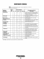
MAINTENANCE SCHEDULE
NOTE: Use the engine hour meter gauge to log your engine hours or record your
engine hours by running time.
SCHEDULED
MAINTENANCE
CHECK
EACH
DAY
HOURS OF OPERATION
50
Raw Water Pump
100
250
750 1000 1250
D
D
Coolant System
Electric Fuel lilt
Pump Filter (if applicable)
500
D
D
D
DC Alternator
D
Feed Pump Strainer
(if applicable)
D
D
D
D
D
D
D
D
D
Remove the pump cover and inspect the impeller,
gasket, cam and cover for wear. Check the bearings
and seals (the shaff can tum, but not wobble).
Lubricate when reassembling.
D
Drain, flush, and refill cooling system with appropriate antifreeze mix.
D
Initial filter change at 50 hours, then change
filter every 250 hours.
D
Check DC charge from alternator. Check mounting
bracket; tighten electrical connections.
D
Clean every 250 operating hours.
Check and adjust injection opening pressure and
spray condition (see ENGINE ADJUSTMENTS).
D
*Fuellnjectors
EXPLANATION OF SCHEDULED
MAINTENANCE
*Starter Motor
D
D
Check solenoid and motor for corrosion. Remove
and lubricate. Clean and lubricate the starter motor
pinion drive.
*Preheat Circuit
D
D
Check operation of preheat solenoid. Remove and
clean glow plugs; check resistance (4-6 ohms).
Reinstall with anti-seize compound on threads.
*Engine Cylinder
Compression
D
D
Check compression pressure and timing (see
ENGINE ADJUSTMENTS).
*Torque Cylinder Head
Hold-down bolts
D
D
D
At first 50 hours, then every 500 hours (see
ENGINE ADJUSTMENTS).
* Adjust the Valve Clearances
D
D
D
Adjust Valve Clearances (see ENGINE
ADJUSTMENTS).
D
Remove, have professionally cleaned and pressure
tested.
*Heat Exchanger
*WESTERBEKE recommends this service be performed by an authorized mechanic.
Engines & Generators
12
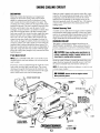
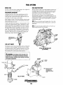
ENGINE COOLING CIRCUIT
DESCRIPTION
When the engine is started cold, external coolant flow is prevented by the closed thermostat (although some coolant flow
is bypassed around the thermostat to prevent the exhaust
manifold from overheating). As the engine warms up, the
thermostat gradually opens, allowing full flow of the engine's
coolant to now unrestricted to the external portion of the
cooling system.
Westerbcke marine diesel generators are designed and
equipped for fresh water cooling. Heat produced in the
engine by combustion and friction is transferred to fresh
water coolant which circulates throughout the engine. This
circulating fresh water coolant cools the engine block and its
internal moving parts. The heat is transferred externally from
the fresh water coolant to raw water by means of a heat
Coolant Recovery Tank
exchanger, similar in function to an automotive radiator. Raw
A coolant recovery tank allows for engine coolant expansion
and contraction during engine operation, without any significant loss of coolant and without introducing air into the cooling system. This tank should be located at or above the
engine manifold level and should he easily accessible.
water flows through the tubes of the heat exchanger while
fresh water coolant flows around the tubes; engine heat transferred to the fresh water coolant is conducted through the
tube walls to the raw water which is then pumped into the
exhaust system where finally it is discharged overboard. In
other words, the engine is cooled by fresh water coolant, this
coolant is cooled by raw water, and the raw water carries the
transferred heat overboard through the exhaust system. The
fresh water coolant and raw water circuits are independent of
each other. Using only fresh water coolant within the engine
allows the cooling water passages to stay dean and free from
harmfu I deposits.
CHANGING COOLANT
The engine's coolant must be changed according to the
MAINTENANCE SCHEDULE. If the coolant is allowed 10
become contaminated, it can lead to overheating problems.
A
CAUTION: Proper cooling system maintenance is
critical; a substantial number of engine failures can be
traced back to cooling system corrosion.
Fresh Water Circuit
NOTE: Refer to ENGINE COOLANT sectiollfor the recommended antifreeze and water mixture to be used as the fresh
Drain the engine coolant by loosening the drain plug on the
engine hlock and opening the manih)ld pressure cap. Flush
the system with fresh water, then start the refill process.
water coo/alll.
Fresh water coolant is pumped through the engine by a circulating pump, absorhing heal from the engine. The coolant
then passes through the themostat into the manifold, to the
heat exchanger where it is cooled and returned to the engine
block via the suction side of the circulating pump.
NOTE: The drain pluf{ 011 the heat exchanger
call
also be used
to drain engine coolant.
A
WARNING: Beware of the hot engine coolant.
Wear protective gloves.
COOLANT RECOVERY TANK
THERMOSTAT
HOUSING
ZINC
ANOOE---
DRAINS
RAW WATER
PUMP
32 KW
llllllliI
TYPICAL ENGINE
COOLING CIRCUIT
f
EXHAUST
RAW WATER
IN
~
WESTERBEKE
Engines & Generators
13
COOlANT
¢
RAW WATER . .
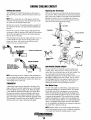
ENGINE COOLING CIRCUIT
Refilling the Coolant
Replacing the Thermostat
After replacing the manifold drain plug, run thc engine at
idle and slowly pour clean, premixed coolant into the manifold.
Remove the cap screws and disassemble the thermostat housing as shown. When installing the new thermostat and gasket
apply a thin coat of sealant on both sides of the gasket before
pressing it into place. Do not over-tighten the cap screws.
Run the engine and check for normal temperatures and that
there are no leaks at the thermostat housing.
NOTE: When a steady flow of coolant appears at the heat
exchanger drain plug opening, close the drain plug and fill
the system until the manifold remains full.
Monitor the coolant in the manifold and add as needed. Fill
the manifold to the filler neck and install the manifold pressure cap.
CAP SCREW
Remove the cap on the coolant recovery tank and fill with
coolant mix to halfway between LOW and MAX and replace
the cap. Run the engine and observe the coolant expansion
flow into the recovery tank.
/
After checking for leaks, stop the engine and allow it to cool.
Coolant should draw back into the cooling system as the
engine cools down. Add coolant to the "recovery tank if
needed. Clean up any spilled coolant.
FROM
AIR BLEED PETCOCK
V"'----COOlANT
TEMPERATURE
SWITCH
GASKET-
COOLANT RETRACTION
THERMOSTAT
TANK
j ) - - - - MANtFOlD PRESSURE CAP
TEMPERATUR
SENDER
TO COOLANT
RECOVERY
TANK
COOLANT EXPANSION
tNSPECT AND CLEAN
THE COOLANT RECOVERY
TANK AND tTS CONNECTING
HOSE EVERY 3 MONTHS
RAW WATER COOLING CIRCUIT
The raw water flow is created by a positive displacement
impeller pump. This pump draws water directly from the
ocean, lake, or river through a hose to the water strainer. The
raw water passes from the strainer through the heat
exchanger (through the heat exchanger tubes) where it cools
the engine circulating fresh water coolant. The raw water is
then discharged into the water injected exhaust elbow, mixing with and cooling the exhaust gasses. This mixture of
exhaust gas and raw water is discharged overboard.
NOTE: Periodically check the condition of the manifold pressure cap. Ensure that the upper and lower rubber seals are in
good condition and check that the vacuum valve opens alld
closes tightly. Carry a spare cap.
THERMOSTAT
Raw Water Pump
A thermostat, located near the manifold at the front of the
engine, controls the coolant temperature, as it continuously
flows through the closed cooling circuit. When the engine
is first started the closed thermostat prevents coolant from
flowing (some coolant is by-passed through a hole in the
thennostat to prevent the exhaust manifold from overheating); as the engine wanns up the thermostat gradually opens.
The thermostat is accessible and can be checked, cleaned, or
replaced easily. Carry a spare thennostat and gasket.
The raw water pump is a self-priming, rotary pump with a
non-ferrous housing and a neoprene impeller. The impeller
has flexible vanes which wipe against a curved cam plate
within the impeller housing, producing the pumping action.
On no account should this pump be run dry, as water acts as
a lubricant for the impeller. There should always be a spare
impeller and impeller cover gasket aboard (an impeller kit).
Raw water pump impeller failures occur when lubricant (raw
water) is not present during engine operation. Such failures
are not warrantable, and operators are cautioned to make sure
raw water flow is present at start-up.
NOTE: Should a failure occur with the pump s illlernal parts
(seals alld bearings) it may be more cost efficient to purchase
a new pump and rebuild the original pump as a spare.
-.yo
WESTERBEKE
Engines & Generators
14
ENGINE COOLING CIRCUIT
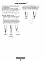
Changing the Raw Water Pump Impeller
Close the raw water intake valve. Remove the pump covcr
and, with the aid of two small screwdrivers, carefully pry the
impeller out of the pump. Install the new impeller and gasket.
Move the blades to conform to the curved cam plate and
push the impeller into the pump's housing. When a<>sern-
bling, apply a thin coating of lubricant to the impeller and
gasket. Open the raw water intake valve.
NEW
CLEAN AND
REPLACE
REPLACE
REUSE
Zinc Anode
A zinc anode, or pencil. is located in the raw water cooling
circuit within the heat exchanger. The purpose of the zinc
anode is to sacrifice itself to electrolysis action taking place
in the raw water cooling circuit. thereby reducing the effects
of electrolysis on other components of the system. The condition of the zinc anode should be checked monthly and the
anode cleaned or replaced as required. Spare anodes should
be carried on hoard.
GASKET
NOTE: Electrolysis acrion is the result of each particular
installalion and vessel location; not that of the generator.
If the zinc pencil needs replacement, hold the hex boss into
which the zinc pencil is threaded with a wrench while loosening the anode with another wrench. This prevents the hex
boss from possibly tearing off the exchanger shell. After
removing the zinc, note the condition of it. If the zinc is in
poor condition, there are probably a lot of zinc tlakes within
the exchanger. Remove the end of the heat exchanger and
clean the inside of all zinc debris. Always have a spare heat
exchanger end gasket in case the present one becomes damaged when removing the end cover. Replace the gasket (refer
to your engine model's heat exchanger end gasket part number), o-ring, cover, and install a new zinc anode.
RAW WATER PUMP
A
CAUTION: If any of the vanes have broken off the
impeller, they must be found to prevent blockage in the
cooling circuit. They can often be found in the heat
exchanger.
Heat Exchanger Service
HEAT EXCHANGER
After approximately 1000 hours of operation, remove, clean
and pressure test the engine's heat exchanger. (A local automotive radiator shop should be able to clean and test the heat
exchanger.)
The heat exchanger is a copper cylinder which encloses a
number of small copper tubes. Raw water is pumped through
the small copper tubes and the freshwater coolant from the
engine is circulated around the copper tubes. The raw water
removes heat from the freshwater coolant.
NOTE: Operating in silty and/or tropical walers may require
that a heat exchanger cleaning he performed more often than
every 1000 hours.
GASKET
OUT
DEBRIS
HEAT EXCHANGER
[32 KW SHOWN]
""'" WESTERBEKE
Engines & Generators
15
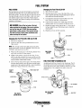
FUEL SYSTEM
DIESEL FUEL
FUEL INJECTION PUMP
Use No.2 diesel fucl with a cetane rating of 45 or higher. Do
not use kerosene or home heating fuel.
The fuel injection pump is the most important component of
the diesel engine and, therefore, calls for the utmost caution
in handling. The fuel injection pump has been thoroughly
bench-tested and should not be tampered with.
FUElJWATER SEPARATOR
A primary fuel filter of the water separating type must be
installed between the fuel tank and the engine to remove
water and other contaminants from the fuel before they can
be carried to the fuel system on the engine.
Speed (hertz) and timing arc the only adjustments the
servicing dealer can perform on the injection pump. Sec the
ENGINE ADJUSTMENT section in this manual. Other types
of adjustments or repairs must be performed by a qualified
injection service shop.
Most installers include a filter/water separator with the installation package as they are aware of the problems that contaminants in the fuel can cause.
NOTE: When servicing the injection pump, the service shop
must be advised that the pump is being used in a generator
applicatioll.
A typical fuel filter/water separator is illustrated below. This
is the Rayeor Model 500 MA. Keep in mind that if a water
separator type filter is not installed between the fuel supply
tank and engine-mounted fuel system, any water in the fuel
will affect the fuel pump, engine filter, and injection equipment. The owner/operator is responsible for making certain
the fuel reaching the engine's injection equipment is free of
impurities. This process is accomplished hy installing .and
maintaining a proper filtration/separation system.
NOTE: The injection pumps should only be serviced by an
authorized fuel injection service facility.
OWNER tNSTALLEO
FUEL WATER/SEPARATOR
FILTER
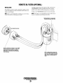
FUEL LIFT PUMPS
Periodically check the fuel connections to and out of the pump
and make sure that no leakage is present and that the fittings
are tight and secure. The DC ground connection at one of the
pump's mounting bolts should be clean and well secured by
the mounting bolt to ensure proper pump operation.
TYPICAL FUEL INJECTION PUMP
125 KW SHOWN]
A WARNING: Fuel leakage at the fuel pump or its
connections is a fire hazard and should be corrected.
Make sure proper ventilation exists whenever servicing
fuel system components.
",,1
TO WtRtNG
HARNESS
__ TO FUEL
FtLTER
TO FUEl FIlTER
'"
NOTE: THE FUELltFT PUMP
ON THE 32 KW tS
AN INTEGRAL PART
OF THE FUEL tNJECTION
PUMP.
FILTER ~"~!l"fr1l1
1:
FUEL LIFT PUMPS
'FUELtN
~GROUND
Engines & Generators
16
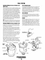
FUEL SYSTEM
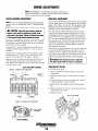
FUEL FILTERS
Changing the Fuel Filter/32.0 KW
1. Shut off the fuel supply.
The fuel injection pump and the fuel injectors arc precisely
manufactured and they must receive clean diesel fuel, free
from water and dirt. To ensure this flow of clean fuel, the fuel
must pass through at least two fuel filters, a fuel water separator and the engine's spin-on fuel filter. Visually inspect,
clean, and change these filters according to the maintenance
schedule in this manual.
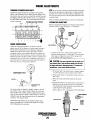
2. Open the bleed screw on top of the filter. Place a container under the fuel filter and open the drain on the bOItom of the bowl and drain the fuel.
3. Close the drain and unscrew the bolt that secures the
bowl. The bowl and filter will drop down.
4. Clean the base. Install a new sealing ring in the base
making certain that it lies squarely on the base recess.
A WARNING: Shut off the fuel valve at the tank
5. Replace the upper scaling ring and the "0" ring in the filter head. Install the new filter element and re-install the
retaining bolt.
when servicing the fuel system. Take care in catching
any fuel that may spill. DO NOT allow any smoking,
open flames or other sources of fire near the fuel sys.
tem when servicing. Ensure proper ventilation exists
when servicing the fuel system.
6. Bleed the air from the filter assembly.
Changing the Fuel Filter/20.0 KW and 25 KW
1. Shut the fuel supply off.
2. Loosen the fucl filter turning counterclockwise with a
filter wrench.
NOTE: The cartridge contains fuel. Take care not La spill it
during disassembly. Perj(Jrm the PRIMING THE FUEL S)SrEM after rep/acing the spin-Oil filler.
SEALING RING
FUEL FILTER
3. Wipe clean the sealing face on the housing bracket with a
rag, so the new filter will seat properly.
[32 KW]
4. Lightly oil the sealing o-ring on the new filter. To reinstall, tum the filter assemhly clockwise carefully until the
o-ring contacts the sealing surface of the housing bracket.
Tum 2/3 further with the filter wrench.
FUEL FEED PUMP STRAINER/32 KW
5. Tum on the fuel and start the engine. The normal preheat
function should quickly prime the system and the engine
should start. If the engine should fail to start immediately,
follow the Priminf!, instructions in this section.
PRESSURE
GAUGE
LOCATION
An additional fuel filter is located in the feed pump. This filter (strainer) is removed for cleaning by releasing the banjo
bolt at the bottom. This strainer should he cleaned every 250
operating hours. Use compressed air and/or clean with
kerosene.
PRIMER (HAND) PUMP
--fi:~2:L r1~~~~1l..
TO FUEl
FtLTER
tN
ta:ll-_-FUELSTRAtNER
--'~FUElIN
FUEL FEED PUMP
[32 KW]
FUEL FILTER
[20 AND 25 KW]
~
WES7ERBEKE
Engines & Generators
17
L__-BANJO BOLT
FUEL SYSTEM
BLEEDING (PRIMING) THE FUEL SYSTEM!20.0 KW
AND 25.0 KW
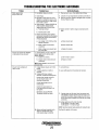
FUEL PRESSURE GAUGE
The 20 KW and 25.0 KW generators have a connector for an
in-line gauge at the secondary fuel filter .This gauge will
indicate the fuel inlet pressure. A positive fuel supply should
read 2.5 to 3.5 psi. Pressure below 1.5 psi will result in poor
engine performance. Low pressure indicates unclean fuel
from the fuel water separator filter. A fuel pressure gauge can
be purchased thru your local marine store.
There is one bleed point in the on-engine fuel system to open
for the removal of air. On the 20.0 KW and 25 KW this bleed
screw is located on the housing for the spin-on fuel filter
mounted on the engine. This screw should be opened one or
two turns to remove air from the upper housing area of the
fuel filter. Energizing the preheat switch for 10-20 seconds or
by using the palm of your hand to slowly depress and release
the primer pump on the top of the filter housing either
method will force air out through the bleed point. Once all
air is expelled, tighten the bleed screw. Depress the preheat
switch 10-20 seconds or slowly pumping the primer on the
fuel filter housing to force any air in the system between the
filter housing and the injection pump out of the system and
back to the fuel tank through the return.
FUEL ADDITIVES
If fungus or bacteria is causing fuel problems you should
have an authorized dealer correct these problems. Then use a
diesel fuel biocide to sterilize the fucl (follow the manufacturers instructions).
SPARES
While the likelihood of having to service the system at sea is
slim, the possibility does exist. Therefore, we recornmend
that banjo washers, injector seat washers, and a fuel filter be
carried on board at all times. Purchase needed spares from
your local WESTERBEKE dealer or distributor. If a leak
should develop at a banjo wa<ihcr that cannot be corrected hy
a simple tightening of the fitting, replace the sealing wa'iher
with a replacement found in the hardware kit for your model.
NOTE: When using the preheat junction to bleed air from the
filter assembly keep in mind that the preheat elements (glow
plugs) are being energized. Take care not to overheat them.
BLEEDING (PRIMING) THE FUEL SYSTEM/32.0 KW
To bleed the fuel system on the 32.0 KW Generators open
the bleed screw on top of the fuel filter and then locate the
fuel feed pump (see illustration).
Unscrew the knob on the fuel feed pump and the cylinder
will pop up. Slowly work this priming pump by pulling the
knob fully upward and pushing it down to achieve a full
pumping stroke. Pump until free of air bubbles from the open
bleed screw, then close the bleed screw.
Disconnect the fuel line return hose. Place towels under the
hose and slowly pump the fuel feed pump again. When clear
fuel, free of air, is discharging frorn the line-stop pumping.
HIGH PRESSURE LINE __
#t tNJECTOR (32 KW)
~
Reconnect the return line and work the purnp a few more
strokes. Then push the cylinder in and secure it.
Start the engine and check/correct any leaks.
PRtMER (HAND) PUMP
Should unstable running occur open the nut that secures the
high pressure line to the injector to expel air in the line.
Loosen 1/2 to a full turn place a cloth over the line and
wrench to catch the spurting fuel. When free of air retighten
the nut and proceed to the next injector line until the engine
runs smoothly. ~
FUEl IN -"" _ _PRESSURE---....
GAUGE
---....
lOCATION
......
FUEL
STRAINER
BLEED SCREW
TO FUEl.--"~-!~
PRIMER (HAND) PUMP
FILTER;;;;~;~~
8
BLEED SCREW
-FUEL IN
FtlTER
FUEL FEED PUMP
[32 KW)
TO FUEL FILTER
FUEL FILTER
(20 KW • 25 KW)
FUEL FILTER
(32 KW)
,..yo
WESTERBEKE
Engines & Generators
18
ENGINE OIL CHANGE
Engine Oil Change
1. Draining the Oil Sump. Discharge the used oil through
Oil COOLER
the sump drain hose (attached to the fronl of the eogine)
while the engine is warm. Drain thc used oil completely,
replace the hose in its bracket, and replace the end cap
securely.
OIL FILTER
(25 KW • 32 KW)
NOTE: Thread size for the luhe oil drain hose capped end
is 1/4 NPT.
_
Always observe the used oj I as it is removed. A
yellow/gray emulsion indicates the presence of water in
the oiL Although this condition is rare, it does require
prompt attention to prevent serious damage. Call a competent mechanic should water be prescnt in the oil. Raw
water present in the oil can be the result of a fault in the
exhaust system attached to the engine and/or a siphoning
of raw water through the raw water cooling circuit into
the exhaust, filling the engine. This problem is often
caused by the poor location, of or the lack of, an antisiphon valve.
I
NOTE: DO NOT OVER TIGHTEN
Oil FilTER
OIL FILTER
(20 KW)
OIL COOLER
3. Filling the Oil Sump. Add new oil through Ihe oil liller
cap on the top of the engine or through the side oil fill.
After refilling, run the generator for a few moments while
checking thc cngine's oil pressure. Make surc there is nn
leakage around the new oil filter or from the oil drain S~iS~
tern, and stop the generator. Then check the quantity of oil
with the lube oil dipstick. Fill to, but not over thc high mark
on the dipstick, should the engine require additional oil.
Immediately after an oil filter change and oil fill. run the
engine to make sure the oil pressure is nOlmal and that
there are no oil leaks around the new oil flltcr.
SUMP DRAIN HOSE
2.
Replacement of the Oil Filter. When removing the used
oil filter, you may find it helpful and cleaner to punch a
hole in the upper and lower portion of the old filter to
drain the oil from it into a container before removing it.
This helps to lessen spillage. A small automotive filter
wrench should be helpful in removing the old oil filter.
NOTE: Generic filters ore flot recommended. (IS the Ill(l/erial standards or diameters of irnportanf items Oil gell('I"i("
parts might be entirel\' different from genuine parts.
NOTE: Do not punch this hole without first loosening the
filter to make certain it can be removed!
A WARNING: Used engine oil contains harmful
contaminants. Avoid prolonged skin contact. Clean skin
and nails thoroughly using soap and water. Launder or
discard clothing or rags containing used oil. Discard
used oil properly.
Place some paper towels and a plastic bag around the filter when unscrewing it to catch any oil left in the filter.
(Oil or any other fluid on the engine reduces the engine's
cooling ability. Please keep your engine clean.) Inspect
the old oil filter as it is removed to make sure that the
ruhber sealing gasket comes off with the old oil filter. If
this rubber sealing gasket remains sealed against the
engine block, gently remove it.
Oil Pressure
The engine's oil pres..'mre, during opcratioI1, is indicated hy thc
oil pressure gauge on thc instrument panel. During normal
operation, the oil pressure will range between 50 and 60 psi.
When installing the new oil filter element, wipe the filter
gasket's sealing surface on the engine block free of oil
and apply a thin coat of clean engine oil to the rubber
gasket on the new oil filter. Screw the filter onto the
threaded oil filter nipple. and then tighten the filter firmly
by hand.
NOTE: A newly started, cold engine can have an oil pressure
reading upwards of 60 psi. A warmed engine can have an oil
pressure reading as low as 35 psi. These readings will vary
depending upon the temperature of the engine alld the load
placed on the generator.
WESTERBEKE
Engines & Generators
19
REMOTE OIL FILTER (OPTIONAL)
INSTALLATION
To install, simply remove the engine oil filter and thread on
WESTERBEKE's remote oil filter kit as shown. Always
install this kit with the oil filter facing down as illustrated.
This popular accessory is used to relocate the engine's oil fiIteT from the engine to a more convenient location such as an
engine room bulkhead.
Contact your WESTERBEKE dealer for more information.
NOTE: Westerheke is 1Iot responsible for engine jailure due to
incorrect installation oj the Remote Oil FillCl:
NOTE: Refer 10 [he ENGINE OIL CHANGE page in [his manual for instructions on removing the oil pIfer.
FASTEN SECURELY TO A BULKHEAD
(SCREWS ARE OWNER SUPPLIED)
20 KW CONNECTION SHOWN
A THIN COAT OF CLEAN OIL TO THE O-RING
WHEN INSTALLING THtS ADAPTER. THREAD THE
ADAPTER ON, THEN TIGHTEN (BY HAND) AN
ADDITIONAL 3/4 TURN AFTER THE O·RING CON·
TACTS THE BASE.
A THIN COAT OF CLEAN OIL TO
THE FILTER GASKET WHEN INSTALLING.
ONCE THE FILTER CONTACTS THE BASE,
THEN TIGHTEN IT AN ADDITIONAL 3/4
TURN.
Engines & Generators
20
DC ELECTRICAL SYSTEM
ENGINE 12-VOLT DC CONTROL CIRCUIT
GLOW PLUGS
The engine has a J 2 vall DC electrical control circuit that is
shown on the wiring diagrams that follow. Refer to these diagrams when troubleshooting or when servicing the DC electrical system on the engine.
The glow plug is a small heater installed in each pre-combustion chamber. They run off the engine starting battery and
become red hot when activated.
The glow plugs are wired through the preheat solenoid.
When PREHEAT is pressed at the control panel this solenoid
should "click" on and the glow plug should begin to get hot.
A CAUTION: To avoid damage to the battery charging
Glow plugs can be checked by unscrewing and holding them
against a good ground (engine block) and turning them on.
The tip should glow red hot You can also use an ammeter to
test the power drain (8 to 9 amps per plug), or an ohmmeter
to test resistance (1.1 to 1.2 ohms).
circuit, never shut off the engine battery switch while
the engine is running. Shut off the engine battery switch,
however, to avoid electrical shorts when working on the
engine's electrical circuit.
A
Battery Specification
WARNING: These glow plugs will become very hot
to the touch. Be careful not to burn your fingers when
testing the plugs.
The minimum recommended capacity of the battery used in
the engine's 12-volt DC conlrol circuit is 300-900 Cold
Cranking Amps CCCA).
Re-install the plugs in the engine and test them again. The
plugs should get very hot (at the tenninal end) within 20 to
25 seconds. If the plugs don't heat up quickly, check for a
short circuit. When reinstalling the glow plugs, use anti-sci/.c
compound on the threads.
Battery Care
Review the manufacturer's recommendations and then establish a systematic maintenance schedule for your engine's
starting batteries and house batteries.
D Monitor your voltmeter for proper charging during engine
A
operation.
CAUTION: 00 not keep glow plug on for more than
30 seconds.
o Check the electrolyte level and specific gravity with a
hydrometer.
D Use only distilled water to bring electrolytes to a proper
level.
----- TE~iMtN.Al END
D Make certain that battery cablc connections are clean and
tight to the battery posts (and to your engine).
o Keep your batteries clean and frec of corrosion.
GLOW PLUGS
A WARNING: Sulfuric acid in lead batteries can
cause severe burns on skin and damage clothing. Wear
protective gear.
AIR INTAKE HEATER
Glow plugs are not used on the 32 KW generator. The preheat solenoid activates a heater clement in the engine's air
intake that quickly heats the air a.s it is drawn into the combustion chamber. There is no maintenance required except an
occasional cleaning of the element and its electrical connectors.
If the element fails to heat up when the preheat sequence is
activated and the solenoid "clicks" on, replace the heater.
-..y"
WESTERBEKE
Engines & Generators
21
DC ELECTRICAL SYSTEM/ALTERNATOR
DESCRIPTION
I. Start the Engine
The charging system consists of an alternator with a voltage
regulator, an engine DC wiring harness, a mounted DC circuit breaker, and a battery with connecting cables_ Because
of the use of integrated circuits (Ie's) the electronic voltage
regulator is very compact and is mounted internally or on the
2. After a few minutes of running measure the starting battery voltage at the battery terminals using a multi-meter
set on DC volts.
The voltage should be
incrca~ing
back of the alternator.
lliID
'14 BROWN =~o=5':I:-:-:=:--
'14 PURPLE
toward 14 volts. If it is,
your altemator is working.
MULTIMETER
o
COM
===~i~~~~~
51 AMP DC
ALTERNATOR
\\~4~":~:@~i/I:.==
(GENERATOR CONNECTIONS) '\
110 RED
(8+ OUTPUT)
TESTING THE STARTING
BATTERY·ALTERNATOR
(ENGINE RUNNING)
TROUBLESHOOTING
GROUND
A
WARNING: A failed alternator can become very
3.
hot. 00 not touch until the alternator has cooled down.
This troubleshooting section is to determine if a problems
,''{isIs with the charging circuit or with the alternator. If it is
'!ermined that the alternator or voltage regulator is bad, it is
,,~t to have a qualified technician check it out.
A 10m ofl'the engine. Inspect all wiring and connections. Insure that the battery terminals and the engine
ground connections arc tight and clean.
l"he alternator charging circuit charges the starting battery and
the service battery. An isolator with a diode, a solenoid, or a
battery selector switch is usually mounted in the circuit to isolate the batteries, so the starting battery is not discharged
along with the service battery. If the alternator is charging the
starting battery but not the service battery, the problem is in
the service battery charging circuit and not with the alternator.
A CAUTION: To avoid damage to the battery
charging circuit, never shut off the engine battery
switch when the engine is running!
B. If a battery selector switch is in the charging circuit,
insure that it is on the correct setting.
Testing the Alternator
A
If the starting hattery voltage remains around 12 volts
after the engine is started and run for a few minutes, a
prohlem exists with the alternator or the charging circuit.
C. 10m on the ignition switch, but do not start the
engine.
D. Check the battery voltage. If your battery is in good
condition the reading should be 12 to 13 volts.
WARNING: Before starting theengine make cer-
tain that everyone is clear of moving parts! Keep away
from sheaves and belts during test procedures.
112.5 )
o
NOTE: Multimeters alld DC Circuits
COM
DC and AC circuits are often mixed together ill marine applications. Always discollnect shore power cords, isolate DC
and A C COflverters and shutdown generators before performing DC testing. No AC tests should be made without proper
knowledge of AC circuits.
MUlTiMETER
+
TESTING THE ALTERNATOR
VOLTAGE
(IGNITION ON - ENGINE OFF)
e
1STARTING BATIERY
~:::;::;
Engines & Generators
22
GROUND
DC ELECTRICAL SYSTEM!ALTERNATOR
E. Now check the voltage between the alternator output
Alternator is Working
terminal (B+) and ground. If the circuit is good. the
voltage at the alternator should be the same as the battery, or if an isolator is in the circuit the alternator voltage will be zero. If not, a problem exists in the circuit
between the alternator and the battery. Check all connections - look for an opening in the charging circuit.
4. Check the voltage of the service battery. This battery
should have a voltage between 13 and 14 volts when the
engine is running. If not, there is a problem in the service
battery charging circuit. Trouhle-shoot the service battery
charging circuit by checking the wiring and connections,
the solenoid, isolator, battery switch and the battery itself.
MUlTiMETER
STARTING BATTERY
@
ALTERNATOR
TESTING THE STARTING
BATIERY·ALTERNATOR
(ENGINE RUNNING)
BAnERY SWITCH /'> ~t
...1_"",,=--' ENGINE
GROUND
SERVICE
BATTERY
F. Start the engine again. Check the voltage between the
~:::::::::;::;;--- TESTING THE SERVICE
alternator output and ground.
The voltage reading for a properly operating alternator
should be between 13.5 and 14.5 volts. If your alternator is OVCf- or undercharging, have it repaired at a reli-
BATIERY (ENGINE RUNNING)
able service shop.
NOTE: Before removing rhe alternator for repair, usc your
it. CAUTION: When performing tests on the alterna·
voltmeter to ensure that 12 volts DC excitaIioll is preselIf
at the EXC terminal if the pn::l'ious test showed only hattery voltage at the B oUlput terminal.
tor charging circuit do not use a high voltage tester fie
Megger}. You can damage the alternator diodes.
If 12 volts is not presenl at the EXC lerrninallrace the
wiring, look for breaks alld poor connections.
"'loY'
WES7ERBEKE
Engines & Generators
23
DC ELECTRICAL SYSTEM
WIRING DIAGRAM #039422
-'00'"
llFTPUMP
~
G-
-
::JII
0D
1.1
o
GLOWPL:S " 0
p:b
I
NOTE 1: An on-off swilch
should be installed in this
circuit to disconnect the
starter from the battery in
an emergency and when
leaving the boat. Twelve
volt diesel engine starters
typically draw 200 10 300
amps when cranking. A
switch with a continuous
raling of 175 amps al 12
VDC will normally serve
this junction, but a switch
must never be used 10
"make" the slarter circuit.
'"
r ------~-~
I
i
I fJ!"
~
PREHEAT
~') ....,~ ~); ~: \I~~~ ::~::H
I
I
~
--1
II~
(6""'•< ~k.
• ~, - ; ~ ..
-VO"
,,"
0 !-'"
!J
SWITCH
STOP
SWITCH
I
STANDARD
j
I
I
I
L_______________ ~ ______ J
Engines & Generators
24
INSTRuMENT
PANEL
DC ELECTRICAL SYSTEM
WIRING SCHEMATIC #039422
~12VDC
, -,
~i
I
:
-
BATTERY
START
SOL
r-----'
: SWITCH
,
-'
,
,
c
SOL
M
,
,
PREHEAT
STARTER
,
,,
-
"
~U~lW~L~S
'-----,
,
,
,,, 'I' ,,
'- ____ J
ALTERNATOR
,.~ )i,ZOA
,I
,
-,
C.B~
)j
IOAI
,:C.8.
, -"
""G~
,;
T82-3
"
SPEED
,
ACTUATOR
START
-,
,---OJ
: r-! ~~6~GENCY
L _lSWITCH
L--
SWITCH
GO~£~NOR
,:;- "
Th
, -, PREHEAT
,,I
Ii
,, : STOP
, _j SWITCH
SPEgs
~R
I
: SWITCH
K
:101"f!L--a.p.
~
~MP
w,r.
E.T.
SW.
~
'-Y
dr/:~E
oe
$
FUEL SOL
'-Y
K
"
W.T.GAUGE
A
,0]
..
VOlTMETER
(1...eJ
WT$
SNDR
SNOR
-
REMOTE START/STOP PANEL
1 _____________________ • J1~ !~~>i'rE
I
r
I
I
I
I/~ED
,-------------- ------- -·-------------t- --- --.-. TO TB1-1
L
#14G~EEN
+
STOP
SWITCH
~AEEN
L--..\....fToTB1-GND
I
#22
I
BLACK I
I
I
I
I
~
, _________
•
I
i
.1A
#10 BLACK
l~E_D~H2.T~_ToTB2-1
I
I 4A PURPLE
!~~~:I~·--;~·~~;:B2-2
\
1
SWITCH
I
I
3A RUN
I
REO
------l-- -- -----.
#14 RED
II ______________________________________
1114 RED
__
L_~!lllE
1-:------------------1
i~~ ~¥~TE
REMOTE PANEL REAR VIEW
-...v WESTERBEKE
Engines & Generators
25
TO T81-2
I
TO T81-4
ELECTRONIC GOVERNOR
ELECTRONIC GOVERNING SYSTEM
•
•
The system is composed of three basic components:
1. Controller - Mounted inside the instrument panel box.
2. Sensor ~ Installed on the generator stator housing over the
flywheel ring gear.
3. Actuator - Mounted at the front of the engine and
attached with linkage to the throttle arm of the injection
SPEED",n
pump.
GAIN
Controller Adjustments
•
1. Speed. - This adjustment is used to raise or lower engine
speed to the desired hertz.
i\.J
CONTROLLER
2. Gain - This adjustment affects the reaction lime of the
actuator to the generator/engine load changes.
PN #303008
NOTE: A high Rajn adjustment can induce an oscillating of
the actuator producing a hunting mode. In such cases, lessen
the gait! adjustment.
, I L'
12 VDC SUPPLY
Calibration
SENSOR
1. With no power to the governor (engine not running)
adjust the GAIN potentiometer to 9:00 o'clock.
PV #039172
2. Start the engine and adjust the speed hy turning the
SPEED potentiometer clockwise to desired speed.
ELECTRONIC GOVERNOR TERMINAL
LINEAR
ACTUATOR
NOTE: COlIlrol/ers are fact01Y adjusled La minimum rpm.
Howeper, j()r safet}!, Olle should he capable ufdisahling the
£!ugill£! ifan (wer::.peed should exist.
3. At no load, turn the GAIN potentiometer clockwise until
the engine hegins to hunt. If the engine does not hunt,
physically upset the governor linkage.
KEEP ACTUATOR
LINKAGE WELL
LUBRICATED
4. Turn the gain potentiometer counterclockwise until the
G?'~~!!'-'"
engine runs stahle.
LINEAR ACTUATOR
(20 KW SHOWN)
TO ELECTRONIC
CONTROLLER
/'
/~ BACK PLATE
FLYWHEEL HOUSING
-..v WESTERBEKE
Engines & Generators
26
TROUBLESHOOTING THE ELECTRONIC GOVERNOR
Problem
System appears dead
{Engine runs at idle.}
Probable Cause
VerificaiionJRemedy
1. Low battery voltage at controller.
1. Check wiring for cause. Check battery state of charge.
2. Stuck linkage.
3. No signal or weak signal from sensor.
(Measure AC voltage from sensor while
engine is running at idle. Voltage should
be 2.5 volts or greater.
4. Check Actuator - depress PREHEAT and
check for battery voltage between
negative black lead at terminal block.
a. Purple lead to black.
2. Lubricate, free up linkage between controller and throttle arm.
3. Check for improperly installed or damaged sensor in flywheel
housing. Replace or adjust
4. Replace controller if battery voltage is not present at both
leads.
b. Second purple to black.
5. Perform the following check between
terminals at the actuator and the negative
DC lead at the controller terminal block,
(Preheat depressed).
a. Low voltage (1.20-2.0 VDC) at either
a. Broken actuator lead.
actuator connection.
h. Battery voltage at both actuator
connections.
b. Broken actuator lead.
c. Battery voltage at one actuator lead
c. Replace the actuator.
but not the other.
Actuator fully extends when PREHEAT
is depressed and stays extended,
1. Check controller. Lift one of the purple
actuator leads from the terminal block.
Depress PREHEAT
a. Actuator fully extends.
a. Short in lead to actuator.
h. Actuator does not fully extend and
connections.
b. Replace controller.
NOTE: Release PREHEAT and reconnect
the purple lead.
Actuator hunts (oscillates) and
engine running.
1. Linkage between actuator and throttle
binding.
2. Improper adjustment of GAIN on
controller.
3. Inadequate DC power supply to
controller, complete the following tests:
1. Lubricatelfree-up.
2. Lessen GAIN adjustment (Recalibrate the ControHer).
Connect a DC voltmeter across the
plus and negative leads at the
controller terminal block.
Lift both purple leads from the
terminal block.
Connect one purple lead to the
C plus terminal and the other to the
DC negative.
Momentarily depress PREHEAT.
The actuator should fully extend.
3. It actuator does not fully extend. check the actuator leads.
If the voltage is less than specified, check for loose or poor
connections, low battery voltage, voltage drop in DC circuit
due to remote panel installation and small wire sizes making
connections.
DC voltage registering on the meter should be:
12 VDC System - 9.6 VDC or higher
24 VDC System - t 9.2 VDC or higher
NOTE: Reconnect actuator leads properly after making this test.
3a. Sensor positioned marginally too tar
away from flywheel teeth giving
erratic signal voltage to controller.
~
33. Check the position of the sensor,
WESTERBEKE
Engines & Generators
27
ENGINE ADJUSTMENTS
NOTE: WESTERBEKE recommends that the following engine adjustments be performed by a competent engine mechanic. The information
below is provided to assist the mechanic.
VALVE CLEARANCE ADJUSTMENT
DRIVE BELT ADJUSTMENT
For your safety, Westerbeke generator models come equipped
with belt guards that cover over the belt(s) on the front of the
engine. ("Out of sight - oul of mind:' The belt guard is NOT
installed lelf that purpose.) Operators are advised that proper
inspection, service, and maintenance is required.
NOTE: Retorque the cylinder head bolts hefore adjusting the
engine:, valves. See TORQUING THE CYLINDER HEAD
BOLTS.
A
CAUTION: Adjust the valve clearance when the
engine is cold. Valves are adjusted by cylinder in the
firing order of the engine. Tighten the cylinder head bolts
to the specified torque before adjusting the valves.
Drive belts must be properly tensioned. Loose drive belts
will not provide proper alternator charging and will eventually damage the alternator. Drive belts that are too tight will
pull the alternator out of alignment and/or cause the alternator to wear out prematurely. Excessive drive belt tension can
also cause rapid wear of the belt and reduce the service life
of the fresh water pump's bearing. A slack belt or the presence of oil on the belt can cause belt slipping, resulting in
high operating temperatures.
Pull off the air breather pipe from the rocker cover, and take
off the rocker cover bolts and the rocker cover to expose the
rocker shaft and valve assembly.
Position the No.1 piston at Top Dead Center (TDC) on its
compression stroke and adjust the # 1, 2, 3 and 6 valves as
The drive belt is properly adjusted if the belt can he deflected
no less than 3/8 inch (IOmm) and no more than 1/2 inch
(12mm) as the belt is depressed with the thumb at the midpoint between the two pulleys on the longest span of the belt.
A spare belt or belts should always be carried on board.
illustrated.
Position the No.4 piston at IDe of its compression stroke
and adjust the # 4, 5, 7 and 8 valves. The valves are numbered 1 to 8 from the front of the engine to the back.
Adjust each valve's clearance by inserting a 0.012 inch (0.3
mm) fecler gauge between the rocker arm and the valve
stem. Make sure to adjust all valves to O'()12 inches (0.3 mm)
while the engine is cold.
A WARNING: Never attempt to check or adjust the
drive belt's tension while the engine is in operation.
Adjusting Belt Tension
VALVE ADJUSTMENT SEQUENCE
1. Remove the belt guard.
WHEN NO.4 CYLINDER IS AT TOP DEAD CENTER
• •
4
3
EXH~UST I
,
2. Loosen the alternator adjusting strap bolt and the base
mounting bolt.
3. With the belt loose, inspect for wear, cracks, and frayed
edges.
I 2 EX~AUST
4 INTAKE
3IN~AKE
4. Pivot the alternator on the base mounting bolt to the left
or right as required, to loosen or tighten.
S. Tighten the base mounting bolt and the adjusting strap
bolt.
6. Operate the generator for about 5 minutes then shut down
and recheck the belt tension.
7. Replace the guard.
2 INTAKE
3 EXHAUST
I
3
1 INTAKE
3/8" TO 1/2" DEFLECTION
11 EXH~UST I
,
,
WHEN NO.1 CYLINDER IS AT TOP DEAD CENTER
=,*=0.01'"' (0.3 MM)
COLO ENGINE
VALVE CLEARANCE
Engines & Generators
28
ENGINE ADJUSTMENTS
TORQUING CYLINDER HEAD BOLTS
NOTE: In case of severe vibrations and detonation noise, have
the injectors checked and overhauled by an authorized fuel
injection service celller. Poor fuel quality, cOlllaminates and
loss of positive fuel pressure to the injection pump will result
in injector faults.
Tighten the cylinder head bolts according to the sequence
shown in the illustration below. Make sure the engine is cold
when this is done, and loosen one head bolt one-half turn and
then righten it between 85 to 90 Ib-f!. (11.8 to 12.5 kg/m) for
the BED 20KW and 25KW. The 32 KW head bolts do NOT
require retorquing.
CYLINDER HEAD BOLT PATTERN
14
'i
2
3
When re-installing the glow plugs use anti-seize compound.
TESTING FUEL INJECTORS
'1
Remove and check fuel injectors. The injector spray pressure
should be 1920 ±71 psi (135 kg/cm' ± 10 kg/cm').
15
INJECTION
PRESSURE
TEST
-16
TESTER
5
4
ENGINE COMPRESSION
Check the compression pressure. To do this, warm the
engine, remove all fuel injectors, or glow plugs, disconnect
the fue! shut-off solenoid wire, and install a compression
adapter in the injector hole or glow plug hole. Connect a
compression tester on the adapter and crank the engine with
the starter motor until the pressure reaches a maximum value.
Repeat this process for each cylinder. Look for cylinders with
dramatically (at least 20%) lower compression than the aver~
age of the others. Compression pressure should not differ by
more than 42.7 psi (3.0 kg/cm2) at 200 rpm.
1. Using the nozzle tester, check the spray pattern and
injection starting pressure of nozzle and, if it exceeds the
limit, adjust or replace the nozzle. When using nozzle
tester, take the following precautions:
A
CAUTION: The spray injected from the nozzle is of
such velocity that it may penetrate deeply into the skin
of fingers and hands, destroying tissue. If it enters the
bloodstream, it may cause blood poisoning.
a. If the diesel fuel of the nozzle tester is stained, replace
it. At the same time, clean or replace the fuel filter.
COMPRESSION TESTER
h. Set the nozzle tester in a clean place where there is no
dust or dirt.
e. Mount the nozzle and nozzle holder on the nozzle
tester.
ADAPTER~ I","~~,.r((
_ t:t5iI["'
---------- Of
d. Operate the hand lever of nozzle tester several times to
bleed the air in the nozzle line, then move the hand
lever at intervals of one stroke per second while reading the injection starting pressure.
______ INJECTOR OR GLOW
i--
PLUG HOLE
If a weak cylinder is flanked by healthy cylinders, the problem is either valve-or piston related. Check the valve clearances for the weak cylinder, adjust as needed and test again.
If the cylinder is still low apply a small amount of oil into'the
cylinder to seal the rings and repeat the test. If compression
comes up - the rings arc faulty.
Start to injection: 135 - 140 kg/cm2 (1920-1990 Ib/in2)
ISHIM THICKNESS
ADJUSTING SHIM
Abnonnally high readings on all cylinders indicate heavy
carbon accumulations, a condition that might be accompanied by high pressures and noise.
~j
I
INJECTOR
"tIY'
WESTERBEKE
Engines & Generators
29
O.lmm
O.2mm
O.3mm
O.5mm
ENGINE ADJUSTMENTS
If the pressure is different from the standard value, adjust to
the specified pressure by increasing or decreasing the thickness of the adjusting shim.
2. Apply the pressure of 115 kg/cm' (1635 Ib/in') to nozzle
by operating the hand lever, and check the drips from the
nozzle tip. If it drips or ha<> a large accumulation of fuel
on the bottom, it is considered defective and should be
replaced. A very small amount of fuel may sometimes
remain on the tip of the nozzle; however, this does not
indicate a defect.
The shim has 10 different thicknesses for every 0.05 mm
(0.0020 in) [rom 1.0 mm (0.0393 in) to 1.95 mm (0.0768 in).
As 0.05 mm (0.0020 in) is increased, approx. 5.0 kg/em'
(7 J.1 Iblin 2) of injection pressure increases.
When replacing the shim, grip the retaining nut in a vise and
remove the body with a wrench. Tighten the retaining nut to
the specified torque.
INSPECTING THE SPRAY PATTERN
1. Operate the hand lever of the nozzle tester at intervals of
one stroke per second to check if the fuel is injected correctly in its axial direction. A nozzle is defective if it
injects fuel in an oblique direction or in several separate
strips. Also, a spray in the fonn of particles indicates a
defect. These defects may sometimes be caused by clogging with dust and, therefore, all parts should be carefully
cleaned before reassembly. (Care should be taken not to
expose one's skin to this spray as it may penetrate the
skin and cause infection.)
NORMAL
FAUlTY ANGLE
•
CORRECT
WRONG
AFTER DRIP TEST
FAULTY DIRECTION
CHATTERING TEST
Engines & Generators
30
ENGINE TROUBLESHOOTING
Note: The engine s electrical system is protected by a 20 amp
manual reset circuit breaker located on a bracket at the rear
of the engine. The preheat solenoid is close by, as is the
emergency STOP switch, which may be mounted on the same
bracket or on the back of the instrument panel, depending
upon [he generator model.
The tables which follow indicate troubleshooting procedures
based upon certain problem indicators, the probable causes of
the problems, and the recommendations to overcome these
problems.
Problem
Key switch on, PREHEAT switch
depressed: no panel indications:
fuel solenoid or electrical fuel pump
Probable Cause
Verification/Remedy
1. Battery Switch not on.
1. Check switch and/or battery connections.
2. Emergency stop sw"itch off.
2. 20-Amp circuit breaker tripped.
2. Check emergency stop SW'ltch posItion.
2. Reset breaker; if breaker trips again, check preheat solenoid
circuit and check circuit for shorts to ground.
3. Check voltage at and after breaker on preheat solenoid.
3. 1a-Amp breaker tripped on
preheat solenoid.
4. Loose battery connections.
START SWITCH DEPRESSED, no starter
engagement.
4. Check (+) connection to starter solenoid and (-) connection to
engine grouna stud. Check battery cable connections
,.
5. Preheat solenoid not operating.
Connection to solenoid faulty.
5. Check solenoid "S" terminal for voltage,
1. Check connection.
2. Faulty switch.
3. Faulty solenoid.
4. Loose battery connections.
2. Check switch with ohmmeter.
3. Check that 12 volts are present at the solenoid connection.
4. Check battery connections.
5. Low battery.
5. Check battery charge stale.
START switch is depressed: panel
indications OK; starter solenoid OK
fuel solenoid not functioning.
1. Poor connections to fuel solenOid.
1. Check connections.
2. Defective fuel solenoid.
Generator engine cranks, but does not
start, fuel solenoid energized.
1. Faulty fueling system.
2. Check thaI 12 volts are present at the (+) connection on the
fuel fun solenoid.
. Check that fuel valves are open,
,
1a. Switch 10 combme house and start batteries.
1b. Replace batteries.
2e. Check fuel lift pump.
Engine can't be stopped.
Battery funs down.
2. Preheat solenoid faulty.
2. Check solenoid.
1. Faulty DC alternator.
1. Oil Pressure switch.
1. Remove Exc. connection at alternator, repair alternator.
1. Observe if gauges and panel lights are activated when engme
2. High resistance leak to ground.
3. Low resistance leak.
Battery not charging
Generator eogme stops.
is not running. Test the 011 pressure switch.
2. Check wiring. Insert sensitive (0 - .25 amp) meter in battery
lines. (Do not start engine.) Remove connections and replace
after short is located.
3. Check all wires for temperature rise to locate the fault.
4. Poor battery connections.
4. Check cable connections at battery for loose connections,
corrosion.
5. DC alternator not charging ..
5. Check connections, check belt tension. test alternator. See
DC ELECTRICAL SYSTEM/ALTERNATOR
1. DC charge circuit faulty.
1. Perform D.C. voltage check of generator charging Clfcuit. See
2. Alternator drive.
Testing the Battery Charging Circuit in this manual.
2. Check drive belt tension. Alternator should turn freely. CheCk
for loose connections. Check output with voltmeter. Ensure 12
volts are present at the Exc. terminal.
1. Fuel lift pump failure.
1. Fuel lift pump should make a distinct ticking sound. Replace
2. Switches and/or wiring loose·
or disconnected.
3. Fuel starvation.
4. 20 Amp circuit breaker tripping.
5. Exhaust system is restricted.
6. Water in fuel.
pump with spare.
2. Inspect wiring for short circuits and loose connections.
Inspect switches for proper operation.
3. Check fuel supply, fuel valves. fuel lift pump.
4. Check for high DC amperage draw during operation.
Ensure breaker is not overly sensitive to heat which would
cause tripping.
5. Check for blockage, collapsed hose, carbon buildup at
exhaust elbow.
6. Pump water from fuel tank(s); change filters and
bleed fuel system.
, "¥I17,WESTERBEKE
I
Engines & Generators
31
ENGINE TROUBLESHOOTING
Problem
Probable Cause
Generator engine overheats/shuts down,
VerificationJRemedy
1. Raw water not circulating.
2. Coolant not circulating.
1. Raw water pump failure. Check impeller - replace.
2. Obstruction at raw water intake or raw water filter,
2a. Thermostat - remove and test in hot water.
Replace thermostat.
2b. Loss of coolant - check hoses, hose clamps, drain plug, etc.
for leaks.
2e. Broken or loose belts - tighten/replace.
Generator engine shuts down,
low oil pressure.
Generator engine shuts down,
High exhaust temperature.
2d. Air leak in system; fun engine and open the pressure cap to
bleed air. Add coolant as needed,
1. Check dipstick, look for oil leaks at oil filter and at
oil drain hose connection.
1. Loss of oiL
2. Oil pressure switch.
1. Exhaust too hot.
2. Replace oil pressure switch
1. Check raw water injection flow, look for exhaust obstruction.
2. High temperature switch opens at .
2. Check for satisfactory operation with switch bypassed,
check with ohmmeter, replace rt faulty.
1. Incorrect grade of engine oil.
too Iowa temperature.
Exhaust smoking problems
1. Blue smoke.
1a. Crankcase is overfilled with engine oil (oil is blowing out
through the exhaust).
2. Engine is running cold
2a. Faulty injector or incorrect injector timing.
3. Improper grade of fuel.
3a. Fuel burn incomplete due to high back pressure in exhaust or
insufficient air for proper combustion (Check for restrictions in
exhaust system: check air intake.).
2. White smoke.
3. Black smoke.
3b. Improperly timed injectors or valves or poor compression.
3c. Lack of air - check air intake and air filter. Check for proper
ventilation
3d. Overload.
TROUBLESHOOTING WATER TEMPERATURE AND OIL PRESSURE GAUGES
If both of the above gauge tests are positive, the gauge is
undoubtedly OK and the problem lies either with the conductor from the sender to the gauge or with the sender.
If the gauge reading is other than what is normally indicated
by the gauge when the instrument panel is energized, the first
step is to check for 12 volts DC between the ignition (B+)
and the Negative (B-) terminals of the gauge.
Assuming that there is 12 volts as required, leave the instrument panel energized and perform the following steps:
If either of the above gauge tests are negative, the gauge is
probably defective and should be replaced.
Assuming the gauge is OK check the conductor from the
sender to the sender terminal at the gauge for continuity.
1. Disconnect the sender wire at the gauge and see if the
gauge reads zero, which is the nonnal reading for this
situation.
2. Remove the wire attached to the sender terminal at the
gauge and connect it to ground. See if the gauge reads
full scale, which is the normal reading for this situation.
~
Check that the engine block is connected to the ground.
Some starters have isolated ground tenninals and if the battery is connected to the starter (both plus and minus terminals), the ground side will not necessarily be connected to the
block.
WESTERBEKE
Engines & Generators
32
GENERATOR INFORMATION
USE OF ELECTRIC MOTORS
Generator Frequency Adjustment
The power required to start an electric motor is considerably
more than is required to keep it running after it is started.
Some motors require much more current to start them than
others. Split-phase (AC) motors require more current to start,
under similar circumstances, than other types. They arc commonly used on easy-starting loads, such as washing
machines, or where loads are applied after the motor is
started, such as small power tools. Because they require 5 to
7 times a'i much current to start as to run, their use should be
avoided, whenever possible, if the electric motor is to be driven by a small generator. Capacitor and repulsion-induction
motors require from 2 to 4 times as much current to start a<;
to run. The current required to start any motor varies with the
load connected to it. An electric motor connected to an air
compressor, for example, will require more current than a
motor to which no load is connected.
Frequency is a direct result of engine/generator speed, as
indicated by the following:
o When the generator is run at 1800 RPM, the AC voltage
output frequency is 60 Hertz.
o When the generator is run at 1500 RPM, the AC voltage
output frequency is 50 Hertz.
Therefore, to change the generator's frequency, the generator's drive engine's speed must be changed. Along with a
reconfiguring of the AC output connections at the generator,
a regulator board voltage output adjustment must also be
made. Sec ELECTRONIC GOVERNOR in this manual.
Generator Maintenance
D Maintaining reasonable cleanliness is important.
Connections of terminal boards and rectifiers may become
corroded, and insulation surfaces may start conducting if
saits, dust, engine exhaust, carbon, etc. arc allowed to
build up. Clogged ventilation openings may cause excessive heating and reduced life of windings.
In geneml, the current required to start 115-Volt motors connected
,.
to medium starting loads will be approximately a~ follows·
MOTOR SIZE
(HP)
_.
---
1/6
1/4
1/3
1/2
3/4
1
AMPS FOR
RUNNING
. _ - - (AMPERESJ...___
.
-
3.2
4.6
5.2
--"'_. ._----7.2
10.2
13
AMPS FOR
STARTING
(AMPERES)
6.4 to 22.4'
9.2 to 32.2' _._10.4 to 72.8'
14.4 to 29.2'
20.4 to 40.8'
26to 52
o For unusually severe conditions, thin rust-inhibiting petroleum-hase coatings, should he sprayed or brushed over all
surfaces to reduce rusting and corrosion. Typical materials
suggested are Dauhert Chemical Co. ·'Non-Rust AC-410"
and Ashland "lectylc 506" or equivalent.
o In addition to periodic cleaning, the generator should be
.-
inspected for (a) tightness of all connections, (h) evidence
of overheated terminals and (c) loose or damaged wires.
*NOTE: III the above table the maximum Amps for Starting is
o The drive discs on single bearing generators should he
more Jar some small motors than for larger ones. The reason
for this is thaI the hardest starting types (split-phase) are not
made in larger sizes.
checked periodically if possihle for tightness of screws
and for any evidence of incipient cracking failure. Discs
should not he allowed to become rusty because rust may
accelerate cracking. The holts which fa~ten the drive disc
to the generator shatt must be hardened steel SAE grade
8, identified by 6 radial marks, one at each of the 6 corners of the head.
Because the heavy surge of current needed for starting
motors is required for only an instant, the generator will not
be damaged if it can bring the motor up to speed in a few
seconds. If difficulty is experienced in starting motors, turn
off all other electrical loads and, if possible, reduce the load
on the electric motor.
o The rear annaturc bearing is lubricated and sealed; no
maintenance is required. However, if the bearing becomes
noisy or rough-sounding) have it replaced.
Required Operating Speed
o Examine bearing at periodic intervals. No side movement
Run the generator first with no load applied, then at half the
generator's capacity, and finally loaded to its full capacity as
indicted on the generator's data plate. The output voltage
should be checked periodically to ensure proper operation of
the generating plant and the appliances it supplies. If an AC
voltmeter or ampmeter is not installed to monitor voltage and
load, check it with a portable meter and amp probe.
of shaft should be detected when force is applied. if side
motion is detectable, bearings are wearing or wear on
shaft of bearing socket outside bearing has occurred.
Repair must be made quickly or major components will
rub and cause major damage to generator.
NOTE: When the vessel in which the generator is installed
cOllfains AC equipment of] 20 volts ollly, it is recommended
that the generator:.. AC terminal block be configured to provide one 120 volt AC hOi leg for the vessel:.. distribution
panel. This will ensure good motor starting response from the
generator.
Engines & Generators
33
THE BE GENERATOR
SINGLE AND THREE PHASE
DESCRIPTION
CIRCUIT BREAKER
This generator is a four-pole, brush less, self-excited generator which requires only the driving force of the engine to produce AC output. The copper and laminated iron in the exciter
stator are responsible for the self-exciting feature of this generator. The magnetic field produced causes an AC voltage to
be induced into the related excitor rotor windings during
rotation. Diodes located in the exciter rotor rectify this voltage to DC;: and supply it to the windings of the rotating field.
This creates an electromagnetic field which rotates through
the windings of the main stator, inducing an AC voltage
which is supplied to a load. An AC voltage is produced in the
auxiliary windings of the main stator and is, in turn, supplied
to a voltage regulator. The regulator produces a DC voltage
to further excite the exciter stator windings, enabling the generator to produce a rated AC output. The voltage regulator
senses AC voltage output and adjusts DC excitation to the
exciter stator winding according to amperage load the generator is furnishing. To maintain a constant voltage output.
A circuit breaker is installed on all WESTERBEKE generators. This circuit breaker will automatically disconnect generator power in case of an electrical overload. The circuit
breaker can be manually shut off when servicing the generator to ensure that no power is coming into the boat.
INTERNAL WIRING SCHEMATIC
I
I
I
I
I
EXCITER
A
+
1
.---:L
r -
-
+ - - - - - - - ..,
-
t
I
~i, ~3
II
t
1
. r-----
E
UD
.::;
'~:
'"
I
t
I
I
I
-U
I
!
:
:
:
:
CIRCUIT
BREAKER
STATOR
I
2
:
3
,
!
6
t
:
:
:
:
:
:
:
:
:
./.
t
~
...J
•
---
,"
/
~[~~
I
I
2
+t _______ ..JI
IL _ _ _
~7':~
I
ROTOR
a'
I
I
B
t
t
REMOVE FOR 50 Hz
t
:
I
BLACK l1
r------,
C
t
3 PHASE TWELVE WIRE RECONNECTABLE
,--------,
NOTE: This circuit breaker is available as a WESTERBEKE
add-on kif for earlier model generators; contact your WESTERBEKE dealer.
,t
•
//
CIRCUIT BREAKER
PART NUMBERS
12
11
10
9
8
7 Ter~~naf
6 Block
o
5
4
3
2
1
20 KW - 60 Hz NO. 42101
]16 KW - 50 Hz NO. 427181
25 KW - 60 Hz NO. 42702
[20 KW - 50 Hz NO. 427111
32 KW - 60 Hz NO. 42703
(25 KW - 50 Hz NO. T 0 BI
FUSE
6.3AMP
1
I
..,.. nr 10
A. EXCITOR
1. Exciter Stator Windings
B.ROTOR
1. Auxiliary Windings a.h.c.
2. Diodes
3. Main Rotor Windings
4. POZ} Resistor
REGULATOR
C. MAIN STATOR
I. Auxiliary Windings
2. - 7 Main Stator Windings
3. Auxiliary Windings
(AC to Regulator)
D. ACTERMINALBOARD
E. REGULATOR
Engines & Generators
34
INTERNAL WIRING SCHEMATICS
r-
-
SINGLE PHASE
~----------..,
EXCITER
STATOR
I
RED
r-----~----------..,
I
I
I
I
I
I
I
I
I
I
EXCITER
ROTOR
iI
ROTOR FIELD
I
I
I
I
AUX
I
I
STATOR
I
I
I
I
I
I
L _____
_ _ _ _ _ ~----------
_________ J
L_
t-------l
~
i
I
I
L
HE"
REO
REO
I
J
®
I-
W2
REGULATOR
w
=>
~
~
"
. ,~
green
~
~D
UOO0-
~
yellow ......
--Hom
§
Am,
Slab
Voll
£
,
,
,,
,
•
i
~
I~
~
~
®
FUSE
Ul
REO
.... JY
Vl
Wl
BLACK
0
I
0
"'t
GREEN
REO
+
i~
BLUE
YELLOW
THREE PHASE
r------------.,
6 WIRE RECONNECTABLE
1------,
EXCITER
I
r -
-
-
-
~
-
-
-
-
-
-
-
-
-
-
-
I
I
I
I
i
I
L _____
L_f-
I
ct-{j
ROTOR
~
I---i--I,
f - . - I
_________
~ tJ2
r __________
I
STATOR
I
. . . !' 'o!lA'' ' '-H1• • •.;_-"'~lAC~'___ l"
GREEN
1
ciRITN---+11
• • •.;--"~---Vl
GREEN
V2 -
I
I
i \\2 TfRiijED,-----~i~::::·'l.--;1----...2R~ED~-/-7wl
I
I
_____
J
I
J
J
REGULATOR
FUSE
6.3 AMP
BLUE
YEllOW
~
WES7ERBEKE
Engines & Generators
35
GENERATOR AC VOLTAGE CONNECTIONS
AC VOLTAGE CONNECTIONS
Generator Frequency
NOTE: The frame ground wire (white/green) must be properly positioned when changing the AC output configuration
of the AC terminal block. For making connections to the AC
terminal block, use tenninal ends for 1/4 inch studs that will
accept multi strand copper wire sized for the amperage rating
from the hot lead connection. The frame ground wire is white
or white with a green strip. It connects between the neutral
stud and the generator frame.
1. Frequency is a direct result of engine/generator speed:
1800 rpm = 60 hertz; 1500 rmp = 50 hertz.
2. To change generator frequency, follow the steps below:
Configure the AC tenninal block for the desired voltage
frequency as shown. Ensure that the case ground wire is
connected to the correct tcmlinal block neutral ground
stud.
NOTE: The while/green ground wire may be removed in those
illSIallaLiOflS where the A C circuit has a separate neutral and
ground circuit. This will prevent the unit from being a ground
source in the vessel.
BE SINGLE PHASE
120/240V - 60 Hz
o
o
0
220V - 50 Hz
120V - 60 Hz
o
0
110V - 50 Hz
o
0
o
0
4
~
0
L1
N
L1
240V - 60 Hz
N
®
l1
N
u'----'
L2
-11,
-11
i,, 00 I,,
100
i,,
,,
,
1 . - - __ --1
,,
-11,
,
100
I,
,,
,
' - - __ --I
' - - __ ---.J
,,
-11,
100
I
,,
,,
' - - __ ---.J
A JUMPER IS REQUIRED FOR 120V - 60 Hz
BRASSJUMP~IE~R~::::::::::::::~::::~~~::~
REMOVE FO~
---+t-DiOOESILEOS
REGULATOR
CIRCUIT
BREAKER
DlOOES/lEOS
220V - 50Hz
20 KW BED SHOWN
l1
CIRCUIT BREAKER
120V - 240V - 60Hz
Engines & Generators
36
l2
N
GENERATOR AC VOLTAGE CONNECTIONS
DESCRIPTION
The regulator is equipped with seven numbered terminals (0
to 6) and their related brass jumpers. The illustrations show
connection points and jumpers for the 3 phase configuration
of the generator. The sensing leads connect between pin #1
and pin #2 on the AC terminal block and connection #2 and
#D on the voltage regulator board.
BLK AVR
H-f--N'GND
NOTE: Series Delta requires the installation of a jumper on
U1
V1
W1
Ll
L2
L3
CASE GND
the regulator board between termillal Band] O.
\
\
J'~
I-
m:
~:,.~
GRN AVR
BLK AVR
H-f--N'GND
\ - "II
170.270V
~ 180.160 V
L' 1
:~
\-
U1
V1
W1
L1
L2
L3
CASE GND
EXCITE~ ~
+
1---,
D=j
1- __ ~60 Hz
GRN GND
BE THREE PHASE (SIX WIRE)
,
3 PHASE VOLTAGE REGULATOR
PARAllEL WYE (STAR)
SERIES WYE (STAR)
SERIES DELTA
@20
020
L-L - 208 VAC
L-N -120 VAC
L-L- 190 VAC
L-N -110 VAC
30
10
30
10
50 Hz
60 Hz
50 Hz
60 Hz
L-LL-N L-LL-N -
450
265
380
220
VAC
VAC
VAC
VAC
30
10
30
10
60 Hz
60 Hz
50 Hz
50 Hz
BE THREE PHASE (TWELVE WIRE)
L-LL2, L3-N L-LL2, L3-N -
240
120
220
110
VAC 3060 Hz
VAC 10 60 Hz
VAC 30 50 Hz
VAC 10 50 Hz
A. SERIES DELTA - Note the
repositioning of Ihe ground
lead from neutral to generator housing.
J. Jumper using #10 AWG
Wire .
....v- WESTERBEKE
Engines & Generators
37
VOLTAGE REGULATOR ADJUSTMENTS
Description
Amp-Hertz
The voltage regulator is an advanced design which ensures
optimum AC alternator performance. It is equipped with
complete protection circuitry to guard against operating
conditions that could be detrimental to the AC alternator.
These two adjustments arc used in conjunction with the two
protection circuits in the voltage regulator that are indicated
by the illumination of a colored LED lights.
l, Delayed overload protection (yellow LED),
2, Low speed protection (red LED),
Both systems have an intervention threshold which can he
adjusted using the respective potentiometer. Each of the two
circuits are able to cause an adequate reduction in excitor
voltage to safeguard the excitor windings and prevent their
overheating.
VOLTAGE REGULATOR
Volts
This potentiometer is used to adjust output voltage. At proper
engine operating speed the output voltage should be held at
:::!:1 % from a no-load condition to a full rated generator output
and from power factor 1.0 - 0.8 with engine drive speed variations up to -6%.
The overload protection system has a delay which permits
temporary overloading of the generator during times such as
motor start-up or other similar load surge demands. The regulator also has a third LED (green), that glows during generator operation to indicate correct operation of the regulator
with the generator.
Setting the Overload Protection
In order to set the AMP overload protection, the alternator
must be loaded to its full output rating.
1. Load the alternator to its rating, then decrease the speed of
the engine by 10,10% (54 Hertz on 60 hertz units, 45
hertz on 50 hertz units),
Prior to starting the engine, turn the VOLT and STAB trimmers (using a mini phillips screwdriver) fully in a counter
clockwise (Minimum) direction until you feci them hit their
2. Rotate the AMP adjustment countcrclockwise until it hits
its stop. Wait about 15-20 seconds after which the AC output of the alternator should drop and thc yellow LED light
should come on.
stops.
Turn the AMP and HERTZ trimmers completely clockwise
(Maximum) in the same manner.
With the alternator running at no-load, at normal speed, and
with VOLT adjust at minimum, it is possible that output voltage will oscillate. Slowly rotate the VOLT adjust clockwise.
The voltage output of the alternator will increase and stabilize. Increase the voltage to the desired value. In this situation, only the green LED will stay lit,
3. Slowly rotate the AMP adjustment clockwise until the
output voltage increases to approximately 97% of the
voltage output at the start of the adjustment. At this point
the yellow LED light should corne on.
4. Return to nominal speed, the yellow LED will turn off
and the alternator voltage will rise to its normal value.
Should this not happen, repeat the adjustment.
Stability
This potentiometer permits variation of the regulator'S
response to generator load changes so as to limit overcompensation and obtain a minimum recovery time to the normal
voltage output.
NOTE: When changing from 60 hertz to 50 hertz operation,
In order to adjust the regulator stability the alternator must be
running at no-load and the output must be monitored.
NOTE: If the unit is operating al 60 /-Iertz ellsure [hal the
jumper strap is in place 011 the regulator board hetween the
Iwo 60 Herlz terminals. III order 10 adjust the ullderspeed
setting, the alternator should be running at lIo-load.
remove the 60 hertz jumper bar from the regulator hoard.
Setting the Underspeed Protection
Tum the STAB adjust slowly clockwise until the voltage
starts to fluctuate. At this point rotate the STAB adjust counterclockwise until the voltage is stable within 1 or 2 tenths of
a volt.
~
cw
~
green
yellow
m
0
E
Slab
'E
m
Volt
"
2. Rotate the Hertz adjustment counterclockwise slowly until
the alternator's AC output voltage starts to decrease and at
the same time the red "LED" light comes on.
red
Hertz
Amp
~
1. To adjust the undcrspeed (low frequency) protection circuit,
lower the engine speed at 90% of its normal running speed
(54 hertz on 60 hertz units, 45 hertz on 50 hertz units.
3. Increase the engine speed to its normal speed (frequency).
The red "LED" light will go out and the AC voltage output will return to normal.
With the above adjustments made, the regulator should function normally.
"
~
VOLTAGE REGULATOR DIAGRAM
Engines & Generators
38
BE TROUBLESHOOTING
NOTE: AC GENERATOR TROUBLESHOOTING MUST
BE PERFORMED WITH ENGINE OPERATING AT 60 HER7Z.
PROBABLE CAUSE
FAULT
No AC voltage output at no load.
1. Short or open in the
main stator winding.
2. Shorted pozi-resistor
on exciter rotor.
3. Four or more shorted or
open diodes on exciter rotor.
4. Short or open in exciter
stator winding.
5. Short or open in rotating
field winding.
Residual voltage produced at no load
15 - 20 volts AC.
1. Blown 6 AMP buse fuse
auxiliary circuit feed to AVR.
2. Faulty voltage regulator.
3. Shorted or open main
stator auxiliary winding.
Low AC voltage output at no load
60 -100 VAC.
1. Open or shorted diodes in
exciter rotor 1 to 3 diodes.
2. Open or shorted exciter
rotor winding.
3. Faulty voltage regulator.
High AC output voltage
150 VAC or higher.
1. Faulty voltage regulator.
Unstable voltage output.
1. STB pod on regulator
needs adjustment.
AC voltage drop under load
60 -100 volts AC.
1. Diode(s) on exciter rotor
breaking down when load is
applied (inductive) 1-3 diodes.
r--
2. Faulty voltage regulator.
----------..,
EXCITER
STATOR
REO
r-----~----------,
I
I
I
I
I
I
:1
I
I
L
EXCITER
ROTOR
I
I
I
I
I
i
I
I
I
I
RED
I
ROTOR FiElD
t-------1
I
@]]
I
I
I
I
I
I
I
I
I
STATOR
:
RED
I
I RED
AUX
_ _ _ _ _ ~---_-_----J
I
I
1
I
L _____ .1
_________ J
w
3m
FUSE
3
,0®
w,
~~
® 1 4
U1
V1
W1
BLACK
GREEN
REO
YELLOW
~
WESTERBEKE
Engines & Generators
39
SHORE POWER TRANSFER SWITCH
SHORE POWER CONNECTIONS (60 HERTZ)
Generator
I N
GI
G2
"
120 VOLT/60 HZ THREE WIRE CONFIGURATION
Notice the repositioning of the white wire ground load on the
terminal hlock to the generator case,
NOTE: D,agrarn shows connections ler a Iwo_
wi'e. 120-VoH system. Fer a Ihree_ wire sySlem
uU dolled lines lor the oth,,, hot leg.
•
.;0.
: TL-___-.
:
-K:D'-',$\ I!
Generator
t
L ____
r-----;;:CD
I
' __ ~i---l-I--'
~
I
,,,
I
,,
,I
/--..,
'--+--~'@
__ .....
~
"
'/-'F:,
f?
;,;
"
3
•
,
, .... --,,
,
,-j--""",
~'+'-+-,
~/
Shlp_lo_ Shore Switch (3 Pole)
I,
PN 32008
L--~l
--1-"'''''"'-'''"'''
_N
(40AmpSlPole)
PH 32009
Ship·lo_ Sho •• Switch (3 pole)
(SOAmpsl Pote)
PN 32010
Ship', Load
PN 32008
(aCAmpatPole)
.~
(125 Amp,l pol,)
•
PH 32133
(200 Amp.f Pole)
"//
~r-;und
NOTE, Oiag.8m shows connection. lor" 1"'0w;,,,.120·Yolt system ',om Ihe gene,alor,
w!lh thr"e-wire, 120-Volt boat system.
~
11
\
F-t-C',wc:,"'"C-
Ships Load
'
~c--';~G""~"'U;)"-'-+--"'1 1
Equ'Omenl
~~_...:,../
~l
Shore Power
If the installer connects shore power to the vessel's AC circuit, this must be done by means of the Shore Power Transfer
Switch. Sct the transfer switch shown in the diagrams to the
OFF position. This switch prevents simultaneous connection
of shore power to generator output.
I S2
PN 32010
(125Ampe/Pole)
Neut.al
N
I
t
,
~
ra~ i~~~~ Pole)
"]
/---',
L-+-+_~""
II'
~~~~;O-VOIt
PN 32133
{200Ampa/Polej
51. N
Sho •• Power
Switching Shore Power to Generator Power
A CAUTION: Heavy motor leads should be shut off
A
CAUTION: Oamage to the generator can result if
utility shore power and generator output are connected
at the same time. This type of generator damage is not
covered under the wa"anty; it is the installer's responsi·
bility to make sure all AC connections are co"ect.
before switching shore power to generator power or
vice·versa because voltage surges induced by switching
with heavy AC loads on the vessel being operated may
cause damage to the exciter circuit components in the
generator.
Engines & Generators
40
LAY-UP AND RECOMMISSIONING
General
Fuel System
Many owners rely on their boatyards to prepare their craft,
including engines and generators, for lay-up during the offseason or for long periods of inactivity. Others prefer to
accomplish lay-up preparation themselves.
Top off your fuel tanks with No.2 diesel fuel. Fuel additives
such as BioBor and Sta-Bil should be added at this time to
control algae and condition the fuel. Care should be taken
that the additives used are compatible with the primary filter/water separator used in the system. Change the element in
your primary fuel filter/water separator, if the fuel system
contains one, and clean the separator sediment bowl.
The procedures which follow will allow you to perfonn your
own lay-up and recommissioning, or to use as a check list if
others do the procedures.
Change the fuel filter elements on the engine and bleed the
fuel system, as needed. Start the engine and allow it to run
for 5 - 10 minutes to make sure no air is left in the fuel system. Check for any leaks that may have been created in the
fuel system during this servicing, correcting them as needed.
Operating the engine for 5-10 minutes will help allow movement of the treated fuel through the injection equipment on
the engine.
These procedures should afford your engine protection during a lay-up and also help familiarize you with the maintenance needs of your engine.
If you have any questions regarding lay-up procedures, call
your local servicing dealer; he will be more than willing to
provide assistance.
Fresh Water Cooling System
Raw Water Circuit
A 50-50 solution of antifreeze and distilled water is recommended for use in the fresh water cooling system at all times.
This solution may require a higher concentration of
antifreeze, depending on the area's winter climate. Check the
solution to make sure the antifreeze protection is adequate.
Close the through-hull sea cock. Remove the raw water
intake hose from the sea cock. Place the end of this hose into
a 5-gallon bucket of clean fresh water. Before starting the
engine, check the zinc anode found in the primary heat
exchanger on the engine and clcan or replace it as required,
and also clean any zinc debris from inside the heal exchanger
where the zinc anode is located. Clean the raw water strainer,
if one is installed, in the inside of the hull.
Should more antifreeze be needed, drain an appropriate
amount from the engine block and add a more concentrated
mixture. Operate the engine to ensure a complete circulation
and mixture of the antifreeze concentration throughout the
cooling system. Now recheck the antifreeze solution's
strength.
Start the engine and allow the raw water pump to draw fresh
water through the system. When the bucket is empty, stop the
engine and refill the bucket with an antifreeze solution
slightly stronger than needed for winter freeze protection in
your area.
Lubrication System
With the engine warm, drain all the lubricating oil from the
oil sump. Remove and replace the oil filter. (Place some
paper towels and a plastic bag around the filter to catch the
oil during its removal.)
Start the engine and allow all of this mixture to be drawn
through the raw water system. Once the bucket is empty, stop
the engine. This antifreeze mixture should protect the raw
water circuit from freezing during the winter lay-up, as well
as providing corrosion protection.
When installing the new oil filter, be sure to apply a small
amount of oil on the rubber sealing gasket at the base of the
filter. Fill the sump with the Correct amount of oil for your
engine. (Refer to the SYSTEM SPECIFICATIONS section of
this manual.) Use an oil with an API specification of CF or
CG-4. Run the generator and check for proper oil pressure
and make sure there are no leaks.
A
Remove the impeller from your raw water pump (some
antifreeze mixture will accompany it, so catch it in a bucket).
Examine the impeller. Acquire a replacement, if needed, and
a cover gasket. Do not replace the impeller (into the pump)
until recommissioning, but replace the cover and gasket.
Intake Manifold and Through-hull Exhaust
CAUTION: Do not leave the engine's old lubricat-
ing oil in the sump over the lay-up period. Lubricating
oil and combustion deposits combine to produce harmful chemicals which can reduce the life of your engine's
internal parts.
,.y-
Place a dean cloth, lightly soaked in lubricating oil, in the
opening of the intake manifold to block the opening. Do not
shove the cloth out of sight. (If it is not visible at recommissioning, and an attempt is made to start the engine, you may
need the assistance of a servicing dealer.) Make a note to
remove the cloth prior to start-up. The through-hull exhaust
port can be blocked in the same manner.
WES1ERBEKE
Engines & Generators
41
LAY-UP AND RECOMMISSIONING
Generator End
Recommissioning
Remove the louvered cover on thc generator end. Check all
wire connections on the AC terminal block and those running
to the bridge rectifier making sure they are secure. Should
these connections appear corroded, they should be removed,
cleaned, and reconnected. Make sure all AC leads are properly cleaned and reconnected. Make sure all AC leads are
properly supported and not chafing as they exit the generator
housing.
The recommissioning of your Westcrbeke engine after a seasonal lay-up generally follows the same procedures as those
presented in the PREPARATIONS FOR STARTING section
regarding preparation for starting and normal starts.
However, some of the lay-up procedures will need to be
counteracted before starting the engine.
1. Remove the oil-soaked cloths from the intake manifold.
2. Remove the raw water pump cover and gasket and discard the old gasket. Install the raw water pump impeller
removed during Jay-up (or replacement, if required).
Install the raw water pump cover with a new cover ga~kct.
Starter Motor
Lubrication and cleaning of the starter drive pinion is advisable, if access to the starter permits its easy removal. Make
sure the battery connections are shut off before attempting to
remove the starter. Take care in properly replacing any electrical connections removed from the starter.
A
CAUTION: Wear rubber gloves, a rubber apron,
and eye protection when servicing batteries. Lead acid
batteries emit hydrogen, a highly explosive gas, which
can be ignited by electrical arcing or a lighted cigarette, cigar, or pipe. Do not smoke or allow an open
flame near the battery being serviced. Shut off all elec·
trical equipment in the vicinity to prevent electrical
arcing during servicing.
Cylinder Lubrication
It is not necessary to remove the fuel injectors from the
cylinder head to squirt light lubricating oil into the cylinders
for the few months of normal lay~up. However, if you anticipate a longer lay~up period (12 months or more), we recommended that this procedure be perfonned. The light oil in the
cylinders will prevent the piston rings from sticking to the
cylinder walls. Make sure you have replacements for the
injector and return line scaling washers.
3. Reinstall the batteries that were removed during the lay~
up, and reconnect the battery cables, making sure the terminals are clean and that the connections are tight. Check
to make sure that the batteries are fully-charged.
Spares
Lay-up time provides a good opportunity to inspect your
Westerheke engine to see if external items such as drive belts
or coolant hoses need replacement. Check your basic spares
kit and order items not on hand, or replace those items used
during the lay-up, such as filters and zinc anodes. Refer to
the SPARE PARTS section of this manual.
4. Check the condition of the zinc anode in the raw water
circuit and clean or replace the anode as needed. Note
that it is not necessary to flush the antifreeze/fresh water
solution from the raw water coolant system. When the
engine is put into operation, the system will self-flush in
a short period of time with no adverse affects. It is advisable to, as either an cnd of season or recommissioning
service to inspect the area that the zinc is located at in the
heat exchanger and clear any and all zinc debris from that
arca.
Batteries
If batteries are to be left on board during the lay-up period,
make sure they are fully charged, and will remain that way,
to prevent them from freezing. If there exists any doubt that
the batteries will not remain fully charged, or that they will
be subjected to severe environmental conditions, remove
the batteries and store them in a warmer, more compatible
environment.
5. Start the engine in accordance with procedures in
the PREPARATIONS FOR STARTING section of
this manual.
""" WESTERBEKE
Engines & Generators
42
SPECIFICATIONS
WESTERBEKE 20 KW BEDA GENERATOR
SPECIFICATIONS
FUEL SYSTEM
Diesel, four-cycle, four-cylinder, fresh
water-cooled Vertical. in-line overhead valve
mechanism (33 hp at 1800 rpm maximum),
General
Open flow, self priming - 1 bleed point
Fuel
No.2 diesel oil (cetane rating of 45 or higher)
Naturally aspirated.
Fuel Injection Pump
ZEXEL Model VE Dislribulor
Governor
Electronic Governing
Fuel Injection TIming
0" TOC (Top Dead Cenler)
Combustion Chamber
Swirl type
Nozzle
Thronle type
Bore & Stroke
3.50 x 4.0 inches (88.9 x 101.6 mm)
Fuel Filter
(on engine)
Spin-on type, full flow
Air cleaner
Metal screen type
Air Flow
(engine combustion)
81.0 cfm (2.29 cmm)
Engine Type
Aspiration
Piston Displacement
154 cubic inches (2.5Iilers)
Firing Order
1-3-4-2
Direction of Rotation
Clockwise, when viewed from the front
Maximum Torque
(al 1800 rpm)
117Ib-ft (16.18 kg-m)
Compression Ratio
21:1
Dimensions
Height: 28.50 inches
Width: 22.00 inches
Length: 45.79 inches
COOLING SYSTEM
(723.9 mm)
(546.1 mm)
(1163.3 mm)
Weighl
943lbs (431.7 kgs)
Fuel Consumplion
(approximate)
2.0 gph (7.57 Iph) al lull raled oulpul
Inclination
Continuous 15 0
Temporary 20 0 (not to exceed 20 min.)
Generator Power Take off
30 Horsepower (maximum)
General
Fresh water-cooled block. Ihermostaticallycontrolled with heat exchanger.
Operating Temperature
170 -190" F (77 - 88" C)
Fresh Water Pump
Centrifugal type, metal impeller, belt-driven
Raw Water Pump
Positive displacement, rubber impeller,
belt driven.
Raw Water Flow,
al 1800 rpm
14.0 gpm (52.9Ipm) (measured
before discharging into exhaust elbow).
System Capacity
(fresh water)
11.5 qls (10.8811Iers)
LUBRICATION SYSTEM
TUNE-UP SPECIFICATIONS
Compression Pressure
427 psi (30 kg/cm1) at 200 rpm
(Limit of difference between
cylinders)
(47.2 psi 130 kg/cm'l)
General
Pressure fed system
Oil Filter
Full flow, paper element, spin-on type
Valve Timing
Sump Capacity
(not including filter)
6.5 U.S. qls (6.15 hlers)
plus filter/cooler assembly
Operating Oil Pressure
(engine hoi)
50-60 pSi (3.5 - 4.2 kg/em')
Oil Grade
API Specification of CF or CG-4,
SAE30, 10W-30, 15W-40
Inlake Opens 17' BTOC
Inlake Closes 47" ABDC
Exhausl Opens 51" BBDC
Exhaust Closes t 3" ATOC
Valve Seat Angle
Intake 45"
Exhaust 30"
Valve Clearance
(engine cold)
Intake 0.Ot2 inches (0.3 mm)
Exhausl 0.012 inches (0.3 mm)
Engine Speed
t 800 RPM 60 Hertz
1500 RPM 50 Hertz
Injector Pressure
1920 + 71-0 psi (135 + 5-0 kg/cm')
Engine Timing
StatiC timed - drop valve method
0.205 + .005 inches BTOC
Engines & Generators
43
SPECIFICATIONS
WESTERBEKE 20 KW BEDA GENERATOR
AC GENERATOR (3 Phase)
ELECTRICAL SYSTEM
Starting Battery
12-Volt, (-) negative ground
Battery Capacity
400 - 600 Cold Cranking Amps (CCA)
DC Charging Alternator
51 Amp rated, belt-dr,,,,,n
Starter
12-Volt, Reduction Gear, 31<W
Starting Aid
Glow plugs, sheathed type
DC No-load Current
±. 2% of rated Amps
DC Cranking Current
250 - 300 Amps (engine cold)
AC GENERATOR (SINGLE PHASE)
General- Single Phase
Brushless, four-pole, revolving field Sealed
lubricated single bearing design.
Reconnectable single phase for 120/240 volts
with solid state voltage regulator.
Voltage - Single Phase
120 or 120/240 Volts - 60 Hertz
230 Volts - 50 Hertz
Voltage regulation:
± 2%
Frequency regulation:
0.30 Hertz no load to full load.
Rating (Volts AC)
20 ¥!IV - 60 Hertz (1800 rpm)
120 Volts 166 Amps
120/240 Volts 166183 Amps
General- 3 Phase
20.0 ¥!IV - 60 Hertz
16.0 ¥!IV - 50 Hertz
Brushless six pole, revolving field.
Sealed lubricated single bearing
design. 12 Lead reconnectable for low voltage
WYE, high voltage Delta. Solid State voltage
regulator with protection circuitry.
Voltage - 3 Phase
(60 Hertz)
Low voltage WYE
High voltage WYE
DELTA
208 volts
480 volts
240 volts
Voltage - 3 Phase
(50 Hertz)
High voltage WYE
DELTA
380 volts
240 volts
Amperage - 3 Phase
(60 Hertz)
Low voltage WfE
High voltage WYE
DELTA
70 Amps
35 Amps
60 Amps
Amperage - 3 Phase
(50 Hertz)
High voltage WYE
DELTA
30.4 Amps
52.5 Amps
GENERATOR COOLING
no load to full load.
Air Requirements
(60 Hertz at 1800 RPM)
425 elm (12.74 emm)
Note: Increase air supply 15% for 50 Hertz operation 1500 rpm
Engine Combustion Air
Requirements
(60 Hertz at 1800 RPM)
16 ¥!IV - 50 Hertz (1500 rpm)
230 Volts 72.7 Amps
-..yo
WESTERBEKE
Engines & Generators
44
81.0 cfm (2.29 cmm)
SPECIFICATIONS
WESTERBEKE 25 KW BED GENERATOR
SPECIFICATIONS
FUEL SYSTEM
Diesel, four-cycle, four-cylinder, fresh
water-cooled, Vertical. in-line overhead valve
mechanism (50 hp at 1800 rpm maximum).
General
Open flow, self priming - 1 bleed point
Fuel
No.2 diesel oil (cetane rating of 45 or higher)
Naturally aspirated.
Fuel Injection Pump
ZEXEL Model VE Oistnbutor
Governor
Electronic Governing
Fuel Injection Timing
0" TOC (Top Dead Center)
Combustion Chamber
Swirl type
Nozzle
Throttle type
Bore & Stroke
3.74 x 4.13 inches (95 x 105 mm)
Fuel Filter
(on engine)
Spin-on type, full flow
Piston Displacement
182 cubic inches (2.98 liters)
Air cleaner
Metal screen type-cleanable
Firing Order
1-3-4-2
Clockwise, when viewed from the front
Air Flow
(engine combustion)
94.6 cfm (2.7 cmm)
Direction of Rotation
Maximum Torque
(at 1800 rpm)
1481b-ft (20.46 kg-m)
Engine Type
Aspiration
Compression Ratio
21 :1
Dimensions
Height: 28.56 inches
Width:
23.3 inches
Length:
49,9 inches
COOLING SYSTEM
(726.4 mm)
(591.8 mm)
(1140.5 mm)
Weight
971 Ibs (440 kgs)
Fuel Consumption
(approximate)
2.9 gph (10.9Iph) at full rated output
Inclination
Continuous 15°
Temporary 20° (not to exceed 20 min.)
Generator Power Take-off
40 Horsepower (maximum)
General
Fresh water-cooled block, thermostaticallycontrolled with heat exchanger.
Operating Temperature
170 -190" F (77 - 88" C)
Fresh Water Pump
Centrifugal type, metal impeller, belt-driven
Raw Water Pump
Positive displacement, rubber impeller,
belt driven.
Raw Water Flow.
at 1800 rpm
15.0 gpm (56.7lpm) (measured
before discllarging into exllaust elbow).
System Capacity
(fresh water)
11.5 qts (10.88 hters)
LUBRICATION SYSTEM
TUNE-UP SPECIFICATIONS
General
Pressure fed system
(limit of difference between
cylinders)
(47.2 psi 13.0 kg/cm'l)
Oil Filter
Full flow. paper element spin-on type
Valve Timing
Sump Capacity
(not including filter)
6.5 U.S. qts (6.15 hters)
plus filter/cooler assembly
Operating Oil Pressure
(englOe hot)
50-60 pSi 13.5 - 4.2 kg/cm')
Oil Grade
API Specification of CF or CG~4,
SAE 30, 10W-30, 15W-40
Compression Pressure
427 psi (30 kg/em') at 200 rpm
Intake Opens 17" BTDC
Intake Closes 4r ABDC
Exhaust Opens 51" BBOC
Exhaust Closes 13" ATDC
Valve Seat Angle
Intake 45"
Exhaust 30"
Valve Clearance
(engine cold)
Intake 0.012 inches (0.3 mm)
Exhaust 0.012 inches (0.3 mm)
Injector Pressure
1920 + 71-0 pSi (135 + 5-0 kg/em')
Engine Timing
Static timed ~ drop valve method
0.205 ± .005 inches BTOC
Engine Speed
1800 RPM 60 Hertz
1500 RPM 50 Hertz
~
WESTERBEKE
Engines & Generators
45
SPECIFICATIONS
WESTERBEKE 25 KW BEDA GENERATOR
ELECTRICAL SYSTEM
Starting Battery
12-Volt. (-) negative ground
AC GENERATOR (3 Phase)
Battery Capacity
400 - 600 Cold Cranking Amps (CCA)
DC Charging Alternator
51 Amp rated, belt-driven
Starter
12-Volt, Reduction Gear
Starting Aid
Glow plugs, sheathed type
DC No-Load Cu rrent
± 2% of rated Amps
DC Cranking Current
250 - 300 Amps (engine cold)
AC GENERATOR (SINGLE PHASE)
General- Single Phase
Brushless, four-pole, revolving field Sealed
lubricated single bearing design.
Reconnectable single phase for 120/240 volts
with solid state voltage regulator.
Voltage - Single Phase
120 or 120/240 Volts - 60 Hertz
220 Volts - 50 Hertz
Voltage regulation:
± 2% no load to full load.
Frequency regulation:
.3 Hertz no load to tuilioad.
Rating (Volts AC)
20 I<!N - 60 Hertz (1800 rpm)
120 Volts 208 Amps
120/240 Volts 208.109 Amps
General- 3 Phase
Brushless six pole, revolving field.
Sealed lubricated single bearing
design. 12 Lead reconnectable for low voltage
WYE and for Delta. Solid State voltage regulator with protection circuitry.
Voltage - 3 Phase
(60 Hertz)
Low voltage WYE
High voltage WYE
DELTA
208 volts
480 volts
240 volts
Voltage - 3 Phase
(50 Hertz)
High voltage WYE
DELTA
380 volts
240 volts
Amperage - 3 Phase
(60 Hertz)
Low voltage WYE
High voltage WYE
DELTA
86.7 Amps
37.6 Amps
75.2 Amps
Amperage - 3 Phase
(50 Hertz)
High voltage WYE
DELTA
38.0 Amps
656 Amps
GENERATOR COOLING
Air Requirements
(60 Hertz at 1800 RPM)
1.0 Power Factor 425 cfm (12.74 cmm)
Note: Increase air supply 15% for 50 Hertz operation 1500 rpm
Engine Combustion Air
Requirements
(60 Hertz at 1800 RPM)
20 I<!N - 50 Hertz (1500 rpm)
220 Volts 87 Amps
"""" WESTERBEKE
Engines & Generators
46
94.6 cfm (2.7 cmm)
SPECIFICATIONS
WESTERBEKE 32 KW BEDA GENERATOR
SPECIFICATIONS
FUEL SYSTEM
Diesel, four-cycle, four-cylinder, fresh
water-cooled, Vertical, in-line overhead valve
mechanism (46 hp at 1800 rpm maximum).
General
Open flow, self priming - 1 bleed point
Fuel
No.2 diesel oil (cetane rating of 45 or higher)
Naturally aspirated.
Fuellnjeclion Pump
ZEXEL Model PE (In-Line)
Governor
Electronic Governing
Fuellnjeclion Timing
12" BTDC
Combustion Chamber
Swirl type
Nozzle
Orifice type
Bore & Stroke
3.94 x 4.33 inches (100.1 x 110.0 mm)
Fuel Filter
Full Flow Replaceable
Engine Type
Aspiration
Piston Displacement
210.8 cubic inches (3.5 liters)
Firing Order
1- 3 - 4 - 2
Direction of Rotation
Clockwise, when viewed from the front
Maximum Torque
(at 1800 rpm)
1661b-ft (23 kg-m)
Compression Ratio
18:1
Dimensions
Height:
Width:
Length:
30.0 inches
22.0 inches
44.6 inches
(on engine)
(762.0 mm)
(558.8 mm)
(113.3 mm)
TUNE·UP SPECIFICATIONS
Compression Pressure
427 psi (30 kg/eml) at 200 rpm
(limit of difference between
cylinde,,)
47.2 psi (3.0 kg/cm'l)
Valve Timing
Air Flow
(engine combustion)
110 cfm (3.1 cmm)
General
Fresh water-cooled block, thermostaticallycontrolled with heat exchanger.
Operating Temperature
170 -190" F (77 - 88" C)
Fresh Water Pump
Centrifugal type, metal impeller, belt-driven
Raw Water Pump
Positive displacement, rubber impeller,
belt driven.
Raw Water Flow,
at 1800 rpm
15.0 gpm (567 Ipm) (measured
before discharging into exhaust elbow).
System Capacity
(fresh water)
8.5 qts (8.04 lite,,)
Intake Opens 19" BTDC
Intake Closes 47° ABDC
LUBRICATION SYSTEM
Exhaust Opens 52" BBDC
Exhaust Closes 14' ATDC
Engine liming
Metal screen type - cleanable
COOLING SYSTEM
10381bs (471.8 kgs)
Weight
Air cleaner
Static timed - drop valve method
0.180 ± .005 inches BTDC
Injector Pressure
2450 ± 35 psi (1 + 5-0 kg/cm')
Valve Seat Angle
Intake 45"
Exhaust 30°
Valve Clearance
(engine cold)
Intake 0.012 inches (0.3 mm)
Exhausl 0.014 inches (0.35 mm)
Engine Speed
1800 RPM 60 Hertz
1500 RPM 50 Hertz
General
Pressure led system
Oil Filler
Full flow, paper element, spin-on type
Sump CapaCity
(not including filter)
6.3 U.S. qts (6.0 liters)
plus filter/cooler assembly
Operating Oil Pressure
(engine hot)
50-60 pSi (3.5 - 4.2 kg/cm')
0,1 Grade
API Specification of CF or CG-4,
SAE 30, lOW-3D, 15W-40
Engines & Generators
47
SPECIFICATIONS
WESTERBEKE 32 KW BEDA GENERATOR
AC GENERATOR (3 Phase)
ELECTRICAL SYSTEM
Starting Battery
12-Volt. (-) nega1ive ground
Battery Capacity
600 - 900 Cold Cranking Amps (CCA)
DC Charging Alternator
51 Amp rated, belt-driven
Starter
12-Volt. 3 KW
Starting Aid
Glow plugs. sheathed type
.1-.2ohm
DC No~Load Current
± 2% of rated Amps
DC Cranking Current
250 - 300 Amps (engine cold)
AC GENERATOR (SINGLE PHASE)
General - 3 Phase
20.0 KW - 60 Hertz
16.0 KW - 50 Hertz
Brushless six pole, revolving field.
Sealed lubricated single bearing
design. 12 Lead reconnectable for low voltage
WYE and for Delta. Solid State voltage regulator with protection circuitry.
Voltage - 3 Phase
(60 Hertz)
Low voltage WYE
High voltage WYE
DELTA
20B volts
480 volts
240 volts
Voltage· 3 Phase
(50 Hertz)
High voltage WYE
DELTA
380 volts
220 volts
Amperage - 3 Phase
(60 Hertz)
.8 power factor
Low voltage WYE
High voltage WYE
DELTA
111.0Amps
48.1 Amps
96.2 Amps
Amperage - 3 Phase
(50 Hertz)
.8 power factor
High voltage WYE
DELTA
47.5 Amps
82.0 Amps
General - Single Phase
Brushless, four-pole, revolving field Sealed
lubricated single bearing design.
Recannectable single phase for 120/240 volts
with solid state voltage regulator.
Voltage - Single Phase
120 or 120/240 Volts - 60 Hertz
220 Volts - 50 Hertz
Voltage regulation:
± 2%
Frequency regulation:
.3 Hertz no load to full load.
Note: Increase air supply 15% for 50 Hertz operation 1500 rpm
Raling (Volts AC)
32 KW - 60 Hertz (1800 rpm)
120 Volts 266 Amps
120/240 Volts 266/133 Amps
Engine Combustion Air
Requirements
(60 Hertz at 1800 RPM)
GENERATOR COOLING
Air Requirements
(60 Hertz at 1800 RPM)
no load to full load.
25 KW - 50 Hertz (1500 rpm)
220 Volts 108. 7 Amps
Engines & Generators
48
1.0 power1actor 500 cfm (15.0 cmm)
110cfm (3.1 cmm)
WESTERBEKE BE GENERATOR 20KW
PARTS IDENTIFICATION
AIR
SILENCER
EXHAUST ELBOW
FUEL
LUBE Oil FILL CAP
EXHAUST TEMPERATURE SWITCH
fUEL LIFT ,"Wle _ _ _ _~~
~---CONTROI PANEL
;:;:::==::--
ZINC ANODE
AC CONNECTIONS OUTLET
FUEL INJECTION PUMP
UNIT DATA TAG
MANUAL PRIMER PUMP
SENSOR
Oil PRESSURE SENDER
FUEL OIL DRAIN HOSE
LUBE OIL DIPSTICK
Oil PRESSURE
LEFT SlOE
OIL FILTER
COOLANT FILL
EMERGENCY STOP
•_ _---UNIT 1.0. PLATE
CHARGING ALTERNATOR
70· EXHAUST ELB!lW-----7
HEAT "CliANIGER/
, '''''''''-'''PUMP
GROUND
fRESH WATER 3LOI;K CIRAIN/
GROUND CONNECTION
RIGHT SlOE
-.Y'
WESTERBEKE
Engines & Generators
49
STARTER WITH SOLENOID
WESTERBEKE BE GENERATOR 25KW
PARTS IDENTIFICATION
AIR INTAKE SILENCER
OIL
CAP
EXHAUST TEMPERATURE SWITCH
fUEL 11FT PLIMP _ _ __
CONTROL PANEL
_--J" CONNECTIONS OUTLET
fUEl RUN SDl.EN(IID-~~-
I DATA TAG
FUEL INJECTION
OIL PRESSURE SENDER
LUBE OIL DIPSTICK
LEFT SIDE
LUBE OIL FILTER
FRESH WATER FILL
, ,_~---'o",,'
1.0. PLATE
DC CHARGING ALTERNATOR
70 EXHAUST ELBDW----0
HEAT EXCHANGER - - -
LED
DRIVE BELTS
RAW WATER PUMP
OIL DRAIN HOSE
GROUND ' " ' ' ' " - -
DC BAnERY GROUND CONNECTION
RIGHT SIDE
WESTERBEKE
Engines & Generators
50
WITH SOLENOID
WESTERBEKE BE GENERATOR 32KW
PARTS IDENTIFICATION
AIR INTAKE ",I"",,,>",,,
ACTUATOR
,EXlrlAU'5TTEMPERArURE SWITCH
_-CONTHOLPANEL
20 AMP DC CIRCUIT BR"'KEI'---
AC CONNECTIONS OUTLET
SIDE Oil FILL
UNIT DATA TAG
FUEL INJECTION
OIL PRESSURE SENDER
FUEL FILTER
LUBE OIL FILTER
LEFT SlOE
ZINC
LUBE OIL FILL GAP
FRESH WATER
CAP
EMERGENCY STOP
I 1.0. PLATE
CHARGING ALTERNATOR
70' EXH"UST ELBOW---_ __
LEO L 1 G H T S - - - - ;
HEAT EXCIHAN,GER/
RAW WATER PUMP
LUBE OIL DRAIN HOSE
GROUND STRAP
OC RAT1<"V
"',o",n CONNECTION
RIGHT SIDE
-.v- WES'lERBEKE
Engines & Generators
51
STARTER WITH SOLENOID
TORQUE SPECIFICATIONS
Ib-ft (m-Kg)
COMPONENT
Cylinder head bolts
Cylinder head cover
Connecting rod cap
Main bearing cap
Camshaft thrust plate
Idler Gear
Rocker arm assembly
Timing gear cover
Rear oil seal cap
Oil pan bolts
Oil pump pipe
Fresh water pump bolts
Crankshaft pulley nut
• Injector to head
Injection pipe flare nut
Intake manifold
Exhaust manifold
Back plate
Flywheel
Damper
Timing gear cover
Altemator bracket
Thermostat housing
Thrust plate
Oil pressure sender
Oil pressure switch
Engine mounts
Alternator bracket
Coolant temperature switch
Coolant temperature sender
Glow plug
Camshaft gear
Injection pump gear
BEDA 20.0 KW
BED 25.0 KW
85 - 89
(11.8 -12.5)
85 -89
(11.8 - 12.5)
2-3
59 -65
(0.3 - 0.45)
2-3
59 -65
(0.3 - 0.45)
(8.2 - 9.0)
80 - 85
12 -17
(11.0 -11.7)
80-85
12 -17
(11.0-11.7)
(1.6 - 2.4)
16 -23
80-85
(2.2 - 3.2)
(11.0-11.7)
12 -17
(1.6 - 2.4)
(1.5 - 2.0)
11 -15
(8.2 - 9.0)
(1.6 - 2.4)
16 -23
(2.2 - 3.2)
80 - 85
12 -17
(11.0 - 11.7)
11 -15
(1.6-2.4)
(1.5 - 2.0)
(1.6 - 2.4)
(0.8 -1.2)
12 -17
6-9
(1.6 - 2.4)
6-9
9 -13
(1.2 -1.8)
253 - 289
43- 51
(35 - 40)
(6.0 - 7.0)
9 -13
253 - 289
12 -17
(1.2 -1.8)
(35 - 40)
(1.6-2.4)
18 -22
12 -17
20 -24
(2.5 - 3.0)
(1.6 - 2.4)
18 - 22
12 -17
(2.5 - 3.0)
(1.6-2.4)
(2.7 - 3.3)
(3.3 - 4.8)
(15.5 -16.3)
(1.9 - 2.7)
20 - 24
24 - 35
112-118
(2.7 - 3.3)
12 -17
24 -35
112-118
14 - 20
12-17
27 - 38
14 - 20
12 -17
(0.8 -1.2)
(3.3 - 4.8)
(15.5-16.3)
(1.9 - 2.7)
(1.6-2.4)
(3.8 - 5.3)
6-8
14 -19
(1.6 - 2.4)
(3.8 - 5.3)
(0.8 -1.1)
(1.9 - 2.6)
27 - 38
6-8
14 -19
9-13
(1.2 - 1.8)
9 -13
9-13
(1.2 -1.8)
23 - 34
27 - 38
(3.2 - 4.7)
9 -13
23 - 34
(3.8 - 5.3)
(2.5 - 4.0)
27 - 38
18 - 29
(2.5 - 4.0)
(1.0 -1.5)
18 - 29
7 -11
(2.5 - 4.0)
(1.0-1.5)
46-69
(6.4 - 9.5)
46 - 69
(6.4 - 9.5)
29 - 52
(4.0 - 9.0)
29 - 52
(4.0 - 9.0)
18 - 29
18 - 29
7 -11
(0.8 - 1.1)
(1.9 - 2.6)
(1.2 - 1.8)
(1.2 -1.8)
(3.2 - 4.7)
(3.8 - 5.3)
(2.5 - 4.0)
BEDA 32.0 KW
(Do Not Torque)
(0.2 - 0.35)
59- 65
(8.2 - 9.0)
(10.0 -10.7)
72-77
14 -19
(1.9 - 2.6)
14 -19
(1.9 - 2.6)
14 -19
(1.9 - 2.6)
14 -19
(1.9 - 2.6)
14 -19
(1.9 - 2.6)
14 -19
(1.9 - 2.6)
(0.8 -1.1)
5.8 - 8
(1.2 -1.8)
9-13
(35 - 40)
253 - 289
12-17
(1.6 - 2.4)
18 - 22
(2.5 - 3.0)
14 -19
(1.9 - 2.6)
(2.3 - 2.7)
17 - 20
(3.8 - 5.3)
28 - 38
(18 - 20)
130-145
(2.2 - 3.4)
16 - 24
14 -19
(1.9 - 2.6)
(3.8 - 5.3)
27 - 38
(0.8 -1.1)
5.8 - 8.0
14 -19
(1.9 - 2.6)
9 -13
(1.2 -1.8)
(1.2-1.8)
9 -13
23 -34
(3.2 -4.7)
27 - 38
(3.8 - 5.3)
(2.5 - 4.0)
18 - 29
18 - 29
(2.5 - 4.0)
NA
NA
29-52
(4.0 - 9.0)
1.4 - 2.5
• BEDA 20 KW Generator uses an injector that is screwed into the head torque 43 - 51 Ib-ft (6.0 - 7.0).
BED 25 KW and 32 KW Generators use injectors that are bolted to the head - torque value is 12 to 17 Ib-ft (1.6 - 2.4) per
bolt tightened evenly.
Engines & Generators
52
STANDARD HARDWARE TORQUES
NOTE: Unless stated otherwise for a ~pecific assembl)~ lise the following torque t'a/ues when lightening standard hardware.
Pitch
Ib-ft
kg-m
6mm bolt head/nut
1
5.B-B.7
0.B-1.2
1.0-1.6
Bmm bolt head/nut
1.25
14.5-21.7
2.0-3.0
13.7-22.4
1.9-3.1
10mm bolt head/nut
1.25
2B.9-39.B
4.0-5.5
1.5
13.0-21.7
1.B-:),0
10mm bolt head/nut
1.5
26.B-37.6
3.7-5.2
12mm bolt head/nut
1.25 (ISO)
25.3-39.B
3.5-5.5
12mm bolt head/nut
1.25 (ISO)
54.2-75.9
7.5-10.5
12mm bolt head/nut
1.5
25.3-39.B
3.5-5.5
12mm bolt head/nut
1.5
50.6-65.1
7.0-9.0
12mm bolt head/nut
1.75
21.7-36.2
3.0-5.0
12mm bolt head/nut
1.75
43.4-61.5
6.0-8.5
13mm bolt head/nut
1.5
32.5-50.6
4.5-7.0
13mm bolt head/nut
1.5
57.9-86.8
8.0-12.0
1.5
72.3-108.5
10.0-15.0
Pitch
Ib-ft
kg-m
6mm bolt head/nut
1
2.9-5.1
0.4-0.7
Bmm bolt head/nut
1.25
7.2-11.6
10mm bolt head/nut
1.25
10mm bolt head/nut
Grade 4
Grade 7T, BT and B.B
14mm bolt head/nut
1.5
36.2-57.9
5.0-B.O
14mm bolt head/nut
14mm bolt head/nut
2
34.0-55.7
4.7-7.7
14mm bolt head/nut
2
68.7-101.3
9.5-14.0
16mm bolt head/nut
1.5
54.2-79.6
7.5-11.0
16mm bolt head/nut
1.5
108.5-166.4
15.0-23.0
16mm bolt head/nul
2
51.4-76.7
7."'0.6
16mm bolt head/nut
2
101.3-159.1
14.0-22.0
1.2-1.5
Grade 5 Cap Screw
Grade 6T
6mm bolt head/nut
1
4.3-6.5
0.6-0.9
1/4 UNC
9-11
Bmm bolt head/nul
1.25
10.B-15.9
1.5-2.2
114 UNF
1,.,3
1.5-1.8
2.5-2.8
10mm bolt head/nut
1.25
21.7-32.5
3.0-4.5
5116 UNC
18-20
10mm bolt head/nut
1.5
19.5-30.4
2.7-4.2
5/16 UNF
21-23
2.9-3.2
12mm bolt head/nut
1.25 (ISO)
36.2-57.9
5.0-B.0
3/8 UNC
28-33
3.7-4.6
12mm bolt head/nut
1.5
36.2-50.6
5.0-7.0
3/8 UNF
30-35
4.1-4.8
4.B-6.B
7/16 UNC
44-49
6.1-6.B
7/16 UNF
50-55
6.9-7.6
1/2 UNC
68-73
9.4-10.1
1/2 UNF
73-80
10."'1.1
12mm bolt head/nut
1.75
34.7-49.2
GENERAL SCREWS
BOLT DlA_
4
0.3 0.5
1.0 -1.3
1.8-2.5
3.0 4.2
5.0 - 7.0
M6
MS
M10
M12
M14
BOLT HEAD MARK
10
7
O.S -1.0
1.0 1.3
2.5 - 3.5
1.5 - 2.2
3.0 4.2
5.0 7.0
9.5 -12.0
5.5 -7.5
16.0 -19.0
8.0-11.0
SEALANTS
PARTS REQUIRING SEALANT
Taper screw 1/2"
Taper screw 1/4"
Taper screw 1/S"
Water drain plug
Oil pressure switch
Side seal
Bearing cap No_ 1
SURFACES REQUIRING SEALANT
(where to mount sealant coated parts)
Thread portion (Gear case)
Thread portion (Cylinder block right side, pump cover)
Thread portion (Cylinder head rear surface)
Thread portion (Cylinder block right side, rear middle portion)
Thread portion (Cylinder block right side surface)
Periphery (Main bearing caps No. t and No.5)
Contact surface with cylinder block
,..yo
WESTERBEKE
Engines & Generators
53
SEALANT
liquid Teflon
liquid Teflon
liquid Teflon
liquid Teflon
liquid Teflon
Permatex #6B
Permatex #6B
METRIC CONVERSIONS
INCHES TO MILLIMETERS
mm
Inches
MILLIMETERS TO INCHES
mm
Inches
--
mm
~~~~-~-
25.40
50.80
76.20
101.60
127.00
254.00
1
2
3
4
5
10
------
10 MILLIMETERS
15
20
25
30
381.00
508.00
635.00
762.00
889.00
1016.00
35
40
1
2
3
4
5
10
-~
..
Meters
-_._-0.0254
0.0508
0.0762
0.1016
0.1270
0.1524
~.~~
1
2
3
4
5
6
mm
Inches
0.0394
0.0787
0.1181
0.1575
0.1969
()=!!j37
15
20
25
30
35
40
0.5906
0.7874
0.9843
1.1811
1.3780
1.5748
=lCENTIMETER, 100 CENTIMETERS =1 METER =39.37 INCHES (3.3 FEET)
INCHES TO METERS
Inches
Inches
-~~
Inches
METERS TO INCHES
Meters
Meters
Inches
Meters
Inches
------
7
0.1778
8
0.2032
9
0.2286
10
0.2540
11
0.2794
12._ _ Q,~()48._
0.1
0.2
0.3
0.4
0.5
0.6
3.937
7.874
11.811
15.748
19.685
23.622
0.7
0.8
0.9
1.0
1.1
1.2
27.559
31.496
35.433
39.370
43.307
47.244
-----------"'-~
TO CONVERT METERS TO CENTIMETERS, MOVE DECIMAL POINT TWO PLACES TO THE RIGHT
YARDS TO METERS
Yards
.
... .
~
Meters
~-
1
2
3
4
5
---'"
METERS TO YARDS
Meters
Yards
Yards
Meters
------
~
0.91440
1.82880
2.74320
3.65760
~no()
6
7
8
9
10
5.48640
6.40080
7.31520
8.22960
9.14400
1
2
3
4
5
Meters
Yards
~~~----
1.09361
2.18723
3.28084
4.37445
5.46807
6
7
8
9
1~._
6.56168
7.65529
8.74891
9.84252
~1 0.93614,
MOVE DECIMAL POINT FOR HIGHER VALUES - •. 9.6,000 METERS = 6,561.68 YARDS
Ib
POUNDS TO KILOGRAMS
kg
Ib
kg
kg
1
2
3
4
5
0.454
0.907
1.361
1.814
2.268
6
2.722
3.175
3.629
4.082
4.536
7
8
9
10
KILOGRAMS TO POUNDS
Ib
kg
._,,-,-
f-.-~~
1
2
3
4
5
GALLONS TO LITERS
Gallons
-~-
1
2
3
4
5
Liters
f---3.79
7.57
11.36
15.14
18.93
~.~~.-~
1
2
3
4
5
1-.
Liters
0.47
0.95
1.42
1.89
2.37
Liters
Liters
Gallons
10
20
30
40
50
37.86
75.71
113.57
151.42
189.28
1
2
5
10
20
0.26
0.53
1.32
2.64
5.28
Pints
8
9
10
..
---~
..
~--~
Liters
40
I
I
5
50
I
I
10
Liters
~
60
I
I
15
2.84
3.31
3.79
4.26
4.73
70
I
I
20
Gallons
-----
60
90
120
150
180
-
Pints
-
1
2
3
4
5
----
15.66
23.77
31.32
39.62
47.54
Liters
75
I
I
25
85
I
I
30
2.11
4.23
6.34
8.45
10.57
95
I
I
35
105
I
I
40
....v- WESTERBEKE
Engines & Generators
54
Pints
~.------
6
7
8
9
10
TEMPERATURE
32
I
I
0
13.228
15.432
17.637
19.842
22.046
LITERS TO PINTS
Liters
6
7
8
9
10
6
7
LITERS TO GALLONS
Gallons
PINTS TO LITERS
Pints
2.205
4.409
6.614
8.818
11.023
Ib
140
I
I
60
175 212
I
I
I
I
80 100
12.68
14.79
16.91
19.02
21.13
OF
°C
SUGGESTED SPARE PARTS
Carry Only Genuine Westerbeke Spare Parts
Thennoslat and
Gasket
-
~Always carry
-~-r,".'. '. ' ca spare set.
'li',-,
I•
I':' "'
,
,
J;
,~'
Fuel Lift Pump Filter
Change every 250
operating hours.
Water Impeller and Gasket
Check every 250 operating hours,
always have a spare set on-board.
Zinc Anodes
Check often, they are
eaten up quickly in
tropical waters and
at marinas, carry
several spares.
./ Fuel Lift Pump
Easy to replace in
case of a failure.
Heat Exchanger End Gasket
Clean out and inspect gasket
at least once a year.
Oil Filters
Replace with every oil change at
every 100 operating hours. Keep
extras on-board.
Fuel Hardware Kit
Fuel line banjo fittings, washers etc. to
fix a leak.
Inspect often, look for
cracking & fraying.
If using a dual sheave
alternator buy
matched pair belts.
Fuel Filters
Carry several on-board, use only genuine
Westerbeke filters. Change every 250
operating hours.
SPARE PARTS KITS
WESTERBEKE also offers two Spare Parts Kits,
B Kit
each packaged in a rugged hinged toolbox.
Kit "A" includes the basic spares.
Kit "B" is for more extensive off-shore cruising.
Impeller Kit
Water Pump Repair Kit
Thermostat Kit
AKit
Impeller Kit
Zinc Anodes
Heat Exchanger Gasket
Complete Gasket Kit
Fuel Filter with Gasket
Heat Exchanger Gasket
Oil Filter
Injector
Drive Belt
Zinc Anodes
Fuel Filter with Gasket
Oil Filter
Fuel Lift Pump Filter
Drive Belt
Fuel Lift Pump Filter
Engines & Generators
55