1
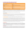
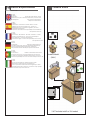
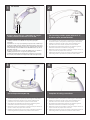
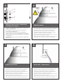
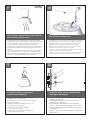
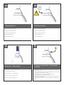
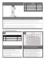
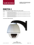
© 2011, Moog Videolarm, Inc. All Rights Reserved RHW75C12N Vandal-Resistant Rugged (Outdoor Dome Housing) www.videolarm.com Installation and Operation Instructions for the following model: RHW75C12N IP Network Ready 7” Vandal-Resistant Outdoor dome housing with wall mount, clear dome polycarbonate, 12VDC input (ideal for solar and battery powered applications), heater/blower, 42vA, for an IP Network PTZ camera. Before attempting to connect or operate this product, please read these instructions completely. To be used with the 81-IN5481 Instruction Manual. W81-IN5318 01-19-2012 IMPORTANT SAFEGUARDS 1 Read these instructions. 2 Keep these instructions. 3 Heed all warnings 4 Follow all instructions. 5 Do not use this apparatus near water. 6 Clean only with damp cloth. 7 CAUTION RISK OF ELECTRIC SHOCK DO NOT OPEN Do not block any of the ventilation openings. Install in accordance with the manufacturers instructions. 8 9 SAFETY PRECAUTIONS Cable Runs- All cable runs must be within permissible distance. CAUTION: TO REDUCE THE RISK OF ELECTRIC SHOCK, DO NOT REMOVE COVER ( OR BACK). NO USER- SERVICEABLE PARTS INSIDE. REFER SEVICING TO QUALIFIED SERVICE PERSONNEL. Mounting - This unit must be properly and securely mounted to a supporting structure capable of sustaining the weight of the unit. Accordingly: a. The installation should be made by a qualified installer. b. The installation should be in compliance with local codes. c. Care should be exercised to select suitable hardware to install the unit, taking into account both the composition of the mounting surface and the weight of the unit. 10 Do not install near any heat sources such as radiators, heat registers, stoves, or other apparatus ( including amplifiers) that produce heat. 11 Do not defeat the safety purpose of the polarized or grounding-type plug. A polarized plug has two blades with one wider than the other. A grounding type plug has two blades and a third grounding prong. The wide blade or the third prong are provided for your safety. When the provided plug does not fit into your outlet, consult an electrician for replacement of the obsolete outlet. 12 Protect the power cord from being walked on or pinched particularly at plugs, convenience receptacles, and the point where they exit from the apparatus. 13 Only use attachment/ accessories specified by the manufacturer. 14 Use only with a cart, stand, tripod, bracket, or table specified by the manufacturer, or sold with the apparatus. When a cart is used, use caution when moving the cart/ apparatus combination to avoid injury from tip-over. 15 Unplug this apparatus during lighting storms or when unused for long periods of time. 16 Refer all servicing to qualified service personnel. Servicing is required when the apparatus has been damaged in any way, such as power-supply cord or plug is damaged, liquid has been spilled of objects have fallen into the apparatus, the The lightning flash with an arrowhead symbol, within an equilateral triangle, is intended to alert the user to the presence of non-insulated “dangerous voltage” within the product’s enclosure that may be of sufficient magnitude to constitute a risk to persons. Este símbolo se piensa para alertar al usuario a la presencia del “voltaje peligroso no-aisIado” dentro del recinto de los productos que puede ser un riesgo de choque eléctrico. Ce symbole est prévu pour alerter I’utilisateur à la presence “de la tension dangereuse” non-isolée dans la clôture de produits qui peut être un risque de choc électrique. Dieses Symbol soll den Benutzer zum Vorhandensein der nicht-lsolier “Gefährdungsspannung” innerhalb der Produkteinschließung alarmieren die eine Gefahr des elektrischen Schlages sein kann. Este símbolo é pretendido alertar o usuário à presença “di tensão perigosa non-isolada” dentro do cerco dos produtos que pode ser um risco de choque elétrico. Questo simbolo è inteso per avvertire I’utente alla presenza “di tensione pericolosa” non-isolata all’interno della recinzione dei prodotti che può essere un rischio di scossa elettrica. apparatus has been exposed to rain or moisture, does not operate normally, or has been dropped. Be sure to periodically examine the unit and the supporting structure to make sure that the integrity of the installation is intact. Failure to comply with the foregoing could result in the unit separating from the support structure and falling, with resultant damages or injury to anyone or anything struck by the falling unit. UNPACKING Unpack carefully. Electronic components can be damaged if improperly handled or dropped. If an item appears to have been damaged in shipment, replace it properly in its carton and notify the shipper. Be sure to save: 1 The shipping carton and packaging material. They are the safest material in which to make future shipments of the equipment. 2 These Installation and Operating Instructions. SERVICE If technical support or service is needed, contact us at the following number: TECHNICAL SUPPORT AVAILABLE 24 HOURS 1 - 800 - 554 -1124 The exclamation point within an equilateral triangle is intended to alert the user to presence of important operating and maintenance (servicing) instructions in the literature accompanying the appliance. Este símbolo del punto del exclamation se piensa para alertar al usuario a la presencia de instrucciones importantes en la literatura que acompaña la aplicación. Ce symbole de point d’exclamation est prévu pour alerter l’utilisateur à la presence des instructions importantes dans la littérature accompagnant l’appareil. Dieses Ausruf Punktsymbol soll den Benutzer zum Vorhandensein de wichtigen Anweisungen in der Literatur alarmieren, die das Gerät begleitet. Este símbolo do ponto do exclamation é pretendido alertar o usuário à presença de instruções importantes na literatura que acompanha o dispositivo. Questo simbolo del punto del exclamaton è inteso per avvertire l’utente alla presenza delle istruzioni importanti nella letteratura che accompagna l'apparecchio. Limited Warranty for Moog Videolarm Products Moog Videolarm warrants these products to be free from defects in material or workmanship as follows: PRODUCT CATEGORY PARTS \ LABOR AllEnclosuresandElectronics* Five(5)Years Poles/PolEvators™/CamEvator Three(3)Years WarriorSeries™/Q-View™/IRIlluminators Five(5)Years SViewSeries™ Five(5)Years**6monthsifusedinautoscan/touroperation Controllers Five(5)Years PowerSupplies Five(5)Years EcoKit Three(3)Years AccessoryBrackets Five(5)Years LibertyDome Three(3)Years *DeputyDome™,NiteTrac™,IglooDome,PurgeDome™ Three(3)Years**6monthsifusedinautoscan/touroperation During the labor warranty period, to repair the Product, Purchaser will either return the defective product, freight prepaid, or deliver it to Moog Videolarm Inc. Decatur GA. The Product to be repaired is to be returned in either its original carton or a similar package affording an equal degree of protection with a RMA # (Return Materials Authorization number) displayed on the outer box or packing slip. To obtain a RMA# you must contact our Technical Support Team at 800.554.1124, extension 101. Moog Videolarm will return the repaired Product freight prepaid to Purchaser. Moog Videolarm is not obligated to provide Purchaser with a substitute unit during the warranty period or at any time. After the applicable warranty period, Purchaser must pay all labor and/or parts charges. The limited warranty stated in these product instructions is subject to all of the following terms and conditions. TERMS AND CONDITIONS 1. NOTIFICATION OF CLAIMS: WARRANTY SERVICE: If Purchaser believes that the Product is defective in material or workmanship, then written notice with an explanation of the claim shall be given promptly by Purchaser to Moog Videolarm. All claims for warranty service must be made within the warranty period. If after investigation Moog Videolarm determines the reported problem was not covered by the warranty, Purchaser shall pay Moog Videolarm for the cost of investigating the problem at its then prevailing per incident billable rate. No repair or replacement of any Product or part thereof shall extend the warranty period of the entire Product. The specific warranty on the repaired part only shall be in effect for a period of ninety (90) days following the repair or replacement of that part or the remaining period of the Product parts warranty, whichever is greater. 2. EXCLUSIVE REMEDY: ACCEPTANCE: Purchaser’s exclusive remedy and Moog Videolarm’s sole obligation is to supply (or pay for) all labor necessary to repair any Product found to be defective within the warranty period and to supply, at no extra charge, new or rebuilt replacements for defective parts. 3. EXCEPTIONS TO LIMITED WARRANTY:Moog Videolarm shall have no liability or obligation to Purchaser with respect to any Product requiring service during the warranty period which is subjected to any of the following: abuse, improper use, negligence, accident, lightning damage or other acts of God (i.e., hurricanes, earthquakes), modification, failure of the end-user to follow the directions outlined in the product instructions, failure of the end-user to follow the maintenance procedures recommended by the International Security Industry Organization, written in product instructions, or recommended in the service manual for the Product. Furthermore, Moog Videolarm shall have no liability where a schedule is specified for regular replacement or maintenance or cleaning of certain parts (based on usage) and the end-user has failed to follow such schedule; attempted repair by non-qualified personnel; operation of the Product outside of the published environmental and electrical parameters, or if such Product’s original identification (trademark, serial number) markings have been defaced, altered, or removed. Moog Videolarm excludes from warranty coverage Products sold AS IS and/or WITH ALL FAULTS and excludes used Products which have not been sold by Moog Videolarm to the Purchaser. All software and accompanying documentation furnished with, or as part of the Product is furnished “AS IS” (i.e., without any warranty of any kind), except where expressly provided otherwise in any documentation or license agreement furnished with the Product. Any cost associated with removal of defective product and installation of replacement product is not included in this warranty. 4. PROOF OF PURCHASE:The Purchaser’s dated bill of sale must be retained as evidence of the date of purchase and to establish warranty eligibility. DISCLAIMER OF WARRANTY EXCEPT FOR THE FOREGOING WARRANTIES, Moog Videolarm HEREBY DISCLAIMS AND EXCLUDES ALL OTHER WARRANTIES, EXPRESS OR IMPLIED, INCLUDING, BUT NOT LIMITED TO ANY AND/OR ALL IMPLIED WARRANTIES OF MERCHANTABILITY, FITNESS FOR A PARTICULAR PURPOSE AND/OR ANY WARRANTY WITH REGARD TO ANY CLAIM OF INFRINGEMENT THAT MAY BE PROVIDED IN SECTION 2-312(3) OF THE UNIFORM COMMERCIAL CODE AND/OR IN ANY OTHER COMPARABLE STATE STATUTE. Moog Videolarm HEREBY DISCLAIMS ANY REPRESENTATIONS OR WARRANTY THAT THE PRODUCT IS COMPATIBLE WITH ANY COMBINATION OF NON-Moog Videolarm PRODUCTS OR NON-Moog Videolarm RECOMMENDED PRODUCTS PURCHASER MAY CHOOSE TO CONNECT TO THE PRODUCT. LIMITATION OF LIABILITY THE LIABILITY OF Moog Videolarm, IF ANY, AND PURCHASER’S SOLE AND EXCLUSIVE REMEDY FOR DAMAGES FOR ANY CLAIM OF ANY KIND WHATSOEVER, REGARDLESS OF THE LEGAL THEORY AND WHETHER ARISING IN TORT OR CONTRACT, SHALL NOT BE GREATER THAN THE ACTUAL PURCHASE PRICE OF THE PRODUCT WITH RESPECT TO WHICH SUCH CLAIM IS MADE. IN NO EVENT SHALL Moog Videolarm BE LIABLE TO PURCHASER FOR ANY SPECIAL, INDIRECT, INCIDENTAL, OR CONSEQUENTIAL DAMAGES OF ANY KIND INCLUDING, BUT NOT LIMITED TO, COMPENSATION, REIMBURSEMENT OR DAMAGES ON ACCOUNT OF THE LOSS OF PRESENT OR PROSPECTIVE PROFITS OR FOR ANY OTHER REASON WHATSOEVER. ! English Español Français Deutsch Portuguese Italiano Electrical Specifications Power 12VDC Contents of Box RHW75 12 VDC 49 Watts Accessories: Heater: 20 Watts, Blower: 2 Watt Camera Power: (See Camera Specifications): 27 Watts Max Tools Required: .100” Flat Head Screwdriver Phillips Head Screwdriver 12 VDC 49 Vatios De Accesorios: Calentador: 20 Watts, Blower: 2 Vatio Energía De la Cámara fotográfica De : (Véase Las Especificaciones De la Cámara fotográfica): 27 Vatios De Herramientas Máximas Requeridas: Destornillador Principal Phillips Del Destornillador Principal Plano Del 100" 12 VDC 49 Watts D'Accessoires : Réchauffeur : 20 Watts, Ventilateur : 2 watts. Puissance D'Appareil-photo : (Voir Les Caractéristiques D'Appareil-photo) : 27 Watts De Maximum Les Outils Ont exigé : Tournevis Principal Phillips De Tournevis Principal Plat De 100". 12 VDC 49 Watt Zusatzgerät-: Heizung: 20 Watts, Blower: 2 Watt-Kamera-Energie: (Sehen Sie Kamera-Spezifikationen): 27 Watt Maximale Werkzeug-Erfordert: 100"Flacher Hauptschraubenzieher-Kreuzkopfhauptschraubenzieher 12 VDC 49 Watts De Acessórios: Calefator: 20 Watts, Blower: 2 Watt Poder Da Câmera De :(Veja Especificações Da Câmera): 27 Watts De Ferramentas Máximas Requereram: Chave de fenda Principal Phillips Da Chave de fenda Principal Lisa Do 100" Pendent Model (ONLY) 12 VDC 49 Watt Di Accessori: Riscaldatore: 20 Watts, Blower: 2 Watt Alimentazione Della Macchina fotografica Da : (Veda Le Specifiche Della Macchina fotografica): 27 Watt Di Attrezzi Massimi Hanno richiesto: Cacciavite Capo "phillips" Del Cacciavite Capo Piano Del 100" * * NOT included with E or 12V models 1 WALL MOUNTING 2 4”-5” Bracket is designed for 45° conduit fitting (If using the conduit). Run wire into bracket secure to wall. • El soporte se diseña para la guarnición del conducto 45° (si usa el conducto). Funcione con el alambre en el soporte seguro para emparedar. • La parenthèse est conçue pour l'ajustage de précision du conduit 45° (si à l'aide du conduit). Courez le fil dans la parenthèse bloquée pour murer. • Haltewinkel ist für Befestigung des Rohres 45° bestimmt (wenn das Rohr verwendet wird). Lassen Sie Draht in den Haltewinkel laufen, der, um zu ummauern sicher ist. • O suporte é projetado para o encaixe da canalização 45° (se usando a canalização). Funcione o fio no suporte seguro para murar. • La staffa è progettata per il montaggio del condotto 45° (se per mezzo del condotto). Faccia funzionare il legare nella staffa sicura per murare. 3 Secure lanyard to lanyard clip Trim incoming control & power wires to 4”- 5”, for either wall or pendent bracket • Con seguridad soporte del montaje a emparedar. Tire del cableado a través del soporte y del ojal de la posición según lo demostrado. • Solidement parenthèse de bâti à murer. Tirez le câblage par la parenthèse et le canon isolant de position comme montré. • Sicher Einfassung Haltewinkel wall. Ziehen Sie Verdrahtung durch Haltewinkel und Position Gummimuffe, wie gezeigt. • Firmemente suporte da montagem a wall. Puxe a fiação através do suporte e do ilhó da posição como mostrado. • Saldamente staffa del supporto da wall. Tiri i collegamenti tramite la staffa ed il gommino di protezione di posizione come indicato. 4 Complete ALL wiring connections • Con seguridad soporte del montaje a emparedar. Tire del cableado a través del soporte y del ojal de la posición según lo demostrado. • Con seguridad soporte del montaje a emparedar. Tire del cableado a través del soporte y del ojal de la posición según lo demostrado. • Solidement parenthèse de bâti à murer. Tirez le câblage par la parenthèse et le canon isolant de position comme montré. • Solidement parenthèse de bâti à murer. Tirez le câblage par la parenthèse et le canon isolant de position comme montré. • Sicher Einfassung Haltewinkel wall. Ziehen Sie Verdrahtung durch Haltewinkel und Position Gummimuffe, wie gezeigt. • Sicher Einfassung Haltewinkel wall. Ziehen Sie Verdrahtung durch Haltewinkel und Position Gummimuffe, wie gezeigt. • Firmemente suporte da montagem a wall. Puxe a fiação através do suporte e do ilhó da posição como mostrado. • Firmemente suporte da montagem a wall. Puxe a fiação através do suporte e do ilhó da posição como mostrado. • Saldamente staffa del supporto da wall. Tiri i collegamenti tramite la staffa ed il gommino di protezione di posizione come indicato. • Saldamente staffa del supporto da wall. Tiri i collegamenti tramite la staffa ed il gommino di protezione di posizione come indicato. 5 WALL MOUNTING 6 ! 26 Watts C Important Gasket Must be in place COAX (coax wire not supplied) Wiring the dome can be completed by referring to the diagram. • Atar con alambre la bóveda puede ser terminada refiriendo al diagrama. • Le câblage du dôme peut être accompli en se rapportant au diagramme. • Das Verdrahten der Haube kann durchgeführt werden, indem man auf das Diagramm sich bezieht. • Wiring a abóbada pode ser terminado consultando ao diagrama. • Legare la cupola può essere completato riferendosi allo schema. 7 To lock turn clockwise Align large arrows • Con seguridad soporte del montaje a emparedar. Tire del cableado a través del soporte y del ojal de la posición según lo demostrado. • Solidement parenthèse de bâti à murer. Tirez le câblage par la parenthèse et le canon isolant de position comme montré. • Sicher Einfassung Haltewinkel wall. Ziehen Sie Verdrahtung durch Haltewinkel und Position Gummimuffe, wie gezeigt. • Firmemente suporte da montagem a wall. Puxe a fiação através do suporte e do ilhó da posição como mostrado. • Saldamente staffa del supporto da wall. Tiri i collegamenti tramite la staffa ed il gommino di protezione di posizione come indicato. 8 Secure with ¼” Allen wrench • Con seguridad soporte del montaje a emparedar. Tire del cableado a través del soporte y del ojal de la posición según lo demostrado. • Con seguridad soporte del montaje a emparedar. Tire del cableado a través del soporte y del ojal de la posición según lo demostrado. • Solidement parenthèse de bâti à murer. Tirez le câblage par la parenthèse et le canon isolant de position comme montré. • Solidement parenthèse de bâti à murer. Tirez le câblage par la parenthèse et le canon isolant de position comme montré. • Sicher Einfassung Haltewinkel wall. Ziehen Sie Verdrahtung durch Haltewinkel und Position Gummimuffe, wie gezeigt. • Sicher Einfassung Haltewinkel wall. Ziehen Sie Verdrahtung durch Haltewinkel und Position Gummimuffe, wie gezeigt. • Firmemente suporte da montagem a wall. Puxe a fiação através do suporte e do ilhó da posição como mostrado. • Firmemente suporte da montagem a wall. Puxe a fiação através do suporte e do ilhó da posição como mostrado. • Saldamente staffa del supporto da wall. Tiri i collegamenti tramite la staffa ed il gommino di protezione di posizione come indicato. • Saldamente staffa del supporto da wall. Tiri i collegamenti tramite la staffa ed il gommino di protezione di posizione come indicato. 9 FOR PENDENT/ WALL MOUNTING 10 4”-5” Trim incoming control and power wires to 4-5 for either wall or pendent bracket • La tapa segura de la cubierta SM5 con mercancías duras proporcionó; termine a la asamblea por las instrucciones SM5 • Le dessus bloqué du logement SM5 avec les articles durs a fourni; accomplissez l'assemblée par instructions SM5 • Sichere Oberseite des Gehäuses SM5 mit den harten Waren bereitgestellt; schließen Sie Versammlung pro Anweisungen SM5 ab • Parte superior segura da carcaça SM5 com os mercadorias duros fornecidos; termine o conjunto por as instruções SM5 • Parte superiore sicura dell'alloggiamento SM5 con gli articoli duri forniti; completi l'assemblea per istruzioni SM5 11 Secure lanyard to lanyard clip • Con seguridad soporte del montaje a emparedar. Tire del cableado a través del soporte y del ojal de la posición según lo demostrado. • Solidement parenthèse de bâti à murer. Tirez le câblage par la parenthèse et le canon isolant de position comme montré. • Sicher Einfassung Haltewinkel wall. Ziehen Sie Verdrahtung durch Haltewinkel und Position Gummimuffe, wie gezeigt. • Firmemente suporte da montagem a wall. Puxe a fiação através do suporte e do ilhó da posição como mostrado. • Saldamente staffa del supporto da wall. Tiri i collegamenti tramite la staffa ed il gommino di protezione di posizione come indicato. 12 26 Watts C COAX (coax wire not supplied) Complete all wiring connections (coax wire not supplied) • Termine todas las conexiones del cableado (alambre coaxil no suministrado) • Accomplissez tous les raccordements de câblage (fil coaxial non fourni) • Schließen Sie alle Verdrahtungsanschlüsse ab (koaxialer Draht nicht geliefert) • Termine todas as conexões da fiação (fio co-axial não fornecido) • Completi tutti i collegamenti dei collegamenti (legare coassiale non fornito) Wiring the dome can be completed by referring to the diagram. • Atar con alambre la bóveda puede ser terminada refiriendo al diagrama. • Le câblage du dôme peut être accompli en se rapportant au diagramme. • Das Verdrahten der Haube kann durchgeführt werden, indem man auf das Diagramm sich bezieht. • Wiring a abóbada pode ser terminado consultando ao diagrama. • Legare la cupola può essere completato riferendosi allo schema. 13 14 Important Gasket Must be in place ! Align large arrows To lock turn clockwise • Alinee las flechas grandes • Alinee las flechas grandes • Alignez les grandes flèches • Alignez les grandes flèches • Richten Sie große Pfeile aus • Richten Sie große Pfeile aus • Alinhe grandes setas • Alinhe grandes setas • Allini le grandi frecce • Allini le grandi frecce 15 Secure with ¼” Allen wrench • Asegure con la llave Allen del ¼” • Fixez clé Allen avec de ¼” • Sichern Sie mit ¼“ Inbusschlüssel • Fixe com chave Allen do ¼ de” • Fissi con chiave di Allen del ¼” 16 ! To loosen - unscrew bolts ½” turn counter clockwise • Para aflojar - desatornille a la derecha contrario de la vuelta del ½ de los pernos” • Pour se desserrer - dans le sens des aiguilles d'une montre de tour dévissez de boulons ½ » contre• Um sich zu lösen - schrauben Sie Schraubbolzen ½“ Umdrehungs-Gegenrechtses herum ab • Para afrouxar - desaparafuse sentido horário contrário volta do ½ dos parafusos da” • Per allentare - sviti in senso orario di girata del ½ dei bulloni„ contro 17 POWER Power and Control Inputs (Outside of Housing) RJ45Camera Power (+ 12 VDC) 24VAC Camera Power (- 12 VDC) 1 2 1 3 2 3 4 4 Red POWER Orange Camera Red Accessory VDC) Camera Power (+12Orange Heater/Blower Yellow Accessory Power (-12 VDC) Heater/Blower Green Max 40 Watts Yellow 52Green Watts CONTROL RJ45 Ethernet Connector 1/0 1 2 3 4 Alarm 1 Alarm 2 Alarm 3 Common Blue Violet Gray White BNC Make the appropriate male and female connections. Indoor model does not include pre-run cables. • Haga las conexiones masculinas y femeninas apropiadas. El modelo de interior no incluye pre-funciona los cables. • Établissez les rapports masculins et femelles appropriés. Le modèle d'intérieur n'inclut pas pré-courent des câbles. • Stellen Sie die passenden männlichen und weiblichen Beziehungen her. Innenmodell schließt nicht vor-laufen lassen Kabel ein. • Faça as conexões masculinas e fêmeas apropriadas. O modelo indoor não inclui pre-funciona cabos. • Faccia i collegamenti maschii e femminili adatti. Il modello dell'interno non include pre-fa funzionare i cavi. Power and Control Inputs (Inside of Housing) 12 19 18 ,5 22 ,75 20 1,0 18 1,5 16 2,5 14 4 12 6 10 MM2 AWG POWER 1 Camera Power (+12 VDC) Red 2 Camera Power (-12 VDC) Orange Make the appropriate male and female connections. Indoor model does not include pre-run cables. • Haga las conexiones masculinas y femeninas apropiadas. El modelo de interior no incluye pre-funciona los cables. • Établissez les rapports masculins et femelles appropriés. Le modèle d'intérieur n'inclut pas pré-courent des câbles. • Stellen Sie die passenden männlichen und weiblichen Beziehungen her. Innenmodell schließt nicht vor-laufen lassen Kabel ein. • Faça as conexões masculinas e fêmeas apropriadas. O modelo indoor não inclui pre-funciona cabos. • Faccia i collegamenti maschii e femminili adatti. Il modello dell'interno non include pre-fa funzionare i cavi. These are recommended distances The beam angle may bemaximum adjusted on the for 12VDC a 10% voltage drop. bottom of with the unit. • Éstos se recomiendan las distancias máximas para 12VDC con una gota del voltage del 10%. • Ceux-ci sont recommandés des distances maximum pour 12VDC avec une chute de tension de 10%. • Diese werden maximale Abstände für 12VDC mit einem 10% Spannungsabfall empfohlen. • Estes são recomendados distâncias máximas para 12VDC com uma queda de tensão de 10%. • Questi sono suggeriti distanze massime per 12VDC con una differenza de potenziale di 10%. PB24 Addendum 20 Additional wires are provided to run power to PB24. Use with connector supplied. Run RJ45 connector through PB24, wall mount, and connect lead from housing. • Los alambres adicionales se proporcionan a la energía funcionada con a PB24. El uso con el conectador proveyó. Funcione con el conectador RJ45 con PB24, emparede el montaje, y conecte el plomo de la cubierta. • Des fils additionnels sont fournis à la puissance courue à PB24. L'utilisation avec le connecteur a fourni. Courez le connecteur RJ45 par PB24, murez le bâti, et reliez le fil du logement. • Zusätzliche Drähte zur Verfügung gestellt zu laufen gelassener Energie zu PB24. Gebrauch mit Verbindungsstück lieferte. Laufen lassen Sie Verbindungsstück RJ45 durch PB24, ummauern Sie Einfassung und anschließen Sie Blei vom Gehäuse n. • Os fios adicionais são fornecidos ao poder funcionado a PB24. O uso com conector forneceu. Funcione o conector RJ45 com PB24, mure a montagem, e conecte a ligação da carcaça. • I legare supplementari sono forniti a potere funzionato a PB24. L'uso con il connettore ha fornito. Faccia funzionare il connettore RJ45 con PB24, muri il supporto e colleghi il cavo da alloggiamento. 21 22 Tab Connect Lanyard to trim ring assembly. • Conecte el acollador con el montaje del anillo del ajuste. • Reliez la lanière à l'anneau d'équilibre. • Schließen Sie Abzuglinie an Ordnung Ring an. • Conecte o colhedor ao conjunto do anel da guarnição. • Colleghi la cordicella al complessivo dell'anello della cornice. Align the arrows on the outside of the dome and lock. • Alinee las flechas en el exterior de la bóveda y trábese. • Alignez les flèches sur l'extérieur du dôme et fermez à clef. • Richten Sie die Pfeile auf der Außenseite der Haube aus und verriegeln Sie sich. • Alinhe as setas na parte externa da abóbada e trave-as. • Allinei le frecce sulla parte esterna della cupola e blocchi. 23 24 Fasten down the dome with a Phillips screwdriver. Wipe the dome clean. Please follow the proper cleaning procedure. • Sujete abajo de la bóveda con un destornillador Phillips. • Limpie la cúpula limpio. Por favor, siga el procedimiento de • Attachez en bas du dôme avec un tournevis Phillips. • Befestigen Sie sich hinunter die Haube mit einem Kreuzkopfschraubenzieher. • Prenda abaixo a abóbada com uma chave de fenda Phillips. • Fissisi giù la cupola con un cacciavite "phillips". limpieza adecuado, como se muestra. • Essuyez le dôme propre. S'il vous plaît suivre la procédure de nettoyage, comme indiqué. • Wischen Sie die Kuppel reinigen. Bitte beachten Sie die ordnungsgemäße Reinigung Verfahren. • Limpe a cúpula limpo. Por favor, siga o procedimento adequado de limpeza conforme. • Pulire la cupola pulito. Si prega di seguire la corretta procedura di pulizia, come. Replacement Parts List 14 RHW75 IRHW75 15 16 13 12 11 10 9 8 7 5 4 6 3 1 2 1 1A 2 3 4 5 5A 6 7 8 8A 9 10 11 12 13 14 15 16 N/S N/S PART NUMBER RC7C RC7T RPRH752 RPRH7503 RPNET02 RPFD072 RPFD072/12 RPFD080 RP40PCMD01 RP70FP7PB RP70FP7PB12 RPFD041 RPFD2612 RPFD3245 RPGK3356 RP3458 RP3551 RP3606 RP3719 RPPKH2098 RPPKE1100 DESCRIPTION CLEAR REPLACEMENT CAPSULE TINTED REPLACEMENT CAPSULE LOWER TRIM RING DOME CLAMPING RING NETWORK HGS POWER SUPPLY 24V HEATER 12V HEATER (12VDC MODELS ONLY) BLOWER CAMERA BRACKET 12VDC CONNECTION PCB(24VAC) CONNECTION PCB (12VDC) HOUSING TOP HOUSING TOP GASKET WALL/PENDENT ADAPTER WALL/PENDENT GASKET LANYARD SET WM11 WALL MOUNT PENDENT MOUNT BRACKET 1 1/2 FEMALE /FEMALE COUPLING BRACKET PACKET ASSEMBLY ELECTRICAL PACKET ASSEMBLY www.videolarm.com © 2011, Moog Videolarm, Inc. All Rights Reserved Camera Mounting Instructions W81-IN5481 01-19-2012 NOTE: ! For all RHP and RHW models a ½” (13mm) spacer is added for additional height. Für alles RHP und RHW modelliert eine ½“ (13mm) Distanzscheibe hinzugefügt für zusätzliche Höhe. Deutsch English Para todo o RHP e RHW modela um espaçador do ½” (13mm) é adicionado para a altura adicional. Para todo el RHP y RHW modela un espaciador del ½” (13m m) se agrega para la altura adicional. Español Portuguese Pour tous les RHP et RHW modèle entretoise de ½ une » (13mm) est ajouté pour la taille additionnelle. Français (HARDWARE) (1) Italiano Per tutti i RHP e RHW modella un distanziatore del ½„ (13mm) si aggiunge per altezza supplementare. (SPACING) (1) (1) (88mm) ½” 1” 2” (88mm) ½” 1” 2” ACTi: ACM 8511 • Mounting holes (4-M3) (4) ARECONT: AV8185 / AV8365 / AV20185 / AV20365 • Mounting holes (4-#8 x ¾”) (4) (4) (75mm) 1” (100mm) 1” 2” AVIGILON: HD-Dome Series • Mounting holes (3-#8) (3) (3) 1” 2” AXIS: 215 • Mounting holes (4-#8) (4) (4) (100mm) 1” (4) (4) (25mm) 1” 1” 2” AXIS: 233D • Mounting holes (4-#8) BASLER: BIP2-1000C-DN / BIP2-1300C-DN / BIP-D1000C-DN / BIP-D1300C-DN • Mounting holes (3-#8) (3) (3) (100mm) 1” 1” 2” CANON: VB-C60 • Mounting holes (1) (1) (1) (64mm) ½” 2” (1) (64mm) ½” 2” (1) (88mm) ½” CANON: VB-M40 • Mounting holes (1) (1) CANON: VB-C300 • Mounting holes (1) (1) 1” 2” ELMO: PTC 400C • Mounting holes (4-#8) (4) (4) (100mm) ½” (38mm) ½” 1” ½” 2” JVC: VN-V686BU / VN-V685U • Mounting holes (3-#8) (3) 1” PANASONIC: BB-HCM580/581 • Mounting holes x (1) (1) (1) (88mm) ½” 1” 2” PANASONIC: WV-CS580 Series • Mounting holes (4-#8) (38mm) ½” 1” PANASONIC: SC386 • Mounting holes (4-#8) (4) (4) (25mm) (4) (50mm) 1” PANASONIC: WV-CS574 • Mounting holes (4-#8) (4) 2” PANASONIC: WV-CS954 / WV-NS954 • Mounting holes (4-#8) (13mm) (4) ½” PANASONIC: WV-NS202 / WV-SC385 / WV-SC384 • Mounting holes (4-#8) (4) (4) (75mm) 1” (3) (25mm) 1” PIXORD: P-463 • Mounting holes (3-#8) (3) 2” SANYO: VCC-HD 5400 • Mounting holes (2-#8) (2) (64mm) 2” ½” SONY: EP / ER Series (520 / 550 / 580) • Mounting holes (4-#8) (4) (4) SONY: RX Series (RX530 / RX550 / RX570) • Mounting holes (4-M3) (4) (38mm) ½” 1” SONY: SNC RH/RS Series (RH124 / RS44 / RS46) • Mounting holes (4-#8) (25mm) (4) 1” SONY: SNC-RZ25 • Mounting holes (2-M3) (2) (1) (1) (1) (13mm) (1) (1) (1) (50mm) ½” SONY: SNC-RZ50 • Mounting holes (2-M3) (2) 2” TOSHIBA: IK-WB16A • Mounting holes (1) (1) (1) (88mm) ½” 2” 1” TOSHIBA: IK-WB21A • Mounting holes (4-#8) (4) (4) (75mm) 1” 2” (75mm) 1” 2” VIDEO IQ: VIQ-CT / CID / CRD / HD-CRD • Mounting holes (4-M4x10) (4) Product Registration/Warranty Thank you for choosing Moog Videolarm. We value your patronage and are solely committed to providing you with the highest quality products available and superior customer service. Should a problem arise, rest assure that Moog Videolarm stands behind its products by offering impressive warranty plans: 3 Years on all Housings, Poles, Power Supplies, and Accessories and 5 Years on camera systems (SView, QView, Warriors), and InfraRed Illuminators. Register Your Products Online Take a few moments and validate your purchase via the Online Product Registration Form at www.videolarm.com/productregistration.jsp Register your recent Moog Videolarm purchases and benefit from the following: • Simple and Trouble-Free RMA process • Added into customer database to receive product updates / news • Eliminate the need to archive original purchase documents: Receipts, Purchase Orders, etc…