1
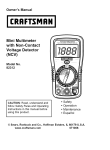
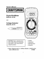
Owner's Manual
JCRAFTSMAN I
Digital MultiMeter
Model
No. 82140
and
Voltage
Model
Detector
No. 82174
CAUTION: Read, understand and
follow Safety Rules and Operating
Instructions in this manual before
using this product.
•
•
•
•
Safety
Operation
Maintenance
EspaSol
© Sears, Roebuck and Co., Hoffman Estates, IL 60179 U.S.A.
www.craftsman.com
070606
II:_ :] ! :[o] |o[o]
_/ / :1 _/ _
Warranty
Page
3
Safety Instructions
4
Safety Symbols
Control and Jacks
5
Symbols and Annunciators
6
Specifications
7
Battery Installation
9
Operating
10
Instructions
6
DC Voltage Measurements
10
AC Voltage Measurements
DC Current Measurements
11
Resistance Measurements
13
Continuity Check
Diode Test
13
Battery Test
Maintenance
14
Replacing Batteries
16
Replacing Fuses
16
Troubleshooting
Service and Parts
17
Model 82174 instructions
18
12
14
15
17
ONE
YEAR
FULL
WARRANTY
ONCRAFTSMAN
MANUAL
RANGING
MULTIMETER
IfthisCRAFTSMAN
Manual
Ranging
MultiMeter
failstogivecomplete
satisfaction
within
oneyear
fromthedateofpurchase,
RETURN
ITTO
THENEAREST
SEARS
STORE
OROTHER
CRAFTSMAN
OUTLET
IN
THEUNITED
STATES,
andSears
willreplace
it,freeofcharge.
IfthisCRAFTSMAN
Manual
Ranging
MultiMeter
isused
forcommercial
orrental
purposes,
thiswarranty
applies
for90days
fromthedate
of
purchase.
Thiswarranty
gives
youspecific
legal
rights,
andyoumayalsohave
other
rights
which
varyfromstate
tostate
Sears,
Roebuck
andCo.,Dept.
817WA,
Hoffman
Estates,
IL60179
For Customer Assistance Call 9am-5 PM (EST)
Monday through Friday 1-888-326-1006
WARNING: USE EXTREME CAUTION IN THE USE OF THIS DEVICE.
Improper use of this device can result in injury or death. Follow all
safeguards suggested in this manual. In addition to the normal safety
precautions used in working with electrical circuits. DO NOT service this
device if you are not qualified to do so.
Thismeter
hasbeen
designed
forsafeuse,butmust
beoperated
with
caution.
Therules
listed
below
must
becarefully
followed
forsafeoperation.
1. NEVER
apply
voltage
orcurrent
tothemeter
thatexceeds
the
specified
maximum:
Input
Limits
Function
Maximum
Input
VAC
600V
DC/AC
VDCorVAC
600V
DC/AC,
200Vrms
on200mV
range
mADC
200mA
250V
fastacting
fuse
ADC
10A250V
fastacting
fuse(30
seconds
max
every
15 minutes)
Resistance,
Continuity
250Vrms for 15sec max
2.
USE EXTREME
3.
DO NOT measure voltage if the voltage on the "COM" input jack
exceeds 500V above earth ground.
CAUTION when working with high voltages.
4.
NEVER connect the meter leads across a voltage source while the
function switch is in the current, resistance, or diode mode. Doing so
can damage the meter.
5.
ALWAYS discharge filter capacitors in power supplies and disconnect
the power when making resistance or diode tests.
6.
ALWAYS turn off the power and disconnect the test leads before
opening the doors to replace the fuse or batteries.
7.
NEVER operate the meter unless the back cover and the battery and
fuse doors are in place and fastened securely.
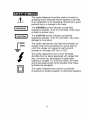
.-"9'_"_
_I:IIIk'dl,,"]k'd
_"+
I:[o] n_
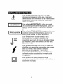
This symbol adjacent to another symbol, terminal or
operating device indicates that the operator must refer
to an explanation in the Operating Instructions to avoid
personal injury or damage to the meter.
IwARN'NG
I
This WARNING symbol indicates a potentially
hazardous situation, which if not avoided, could result
in death or serious injury.
CAUTION symbol indicates a potentially
I CAUTION
I This
hazardous situation, which if not avoided, may result
damage to the product.
[-MAX
500V
m
m
This symbol advises the user that the terminal(s) so
marked must not be connected to a circuit point at
which the voltage with respect to earth ground
exceeds (in this case) 500 VAC or VDC.
This symbol adjacent to one or more terminals
identifies them as being associated with ranges that
may, in normal use, be subjected to particularly
hazardous voltages. For maximum safety, the meter
and its test leads should not be handled when these
terminals are energized.
This symbol indicates that a device is protected
throughout by double insulation or reinforced insulation.
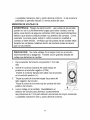
o_o]_IIII_,To]L',]F:I _Ie]LnlT:T_
[_:
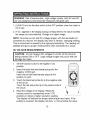
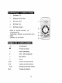
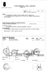
1.
LCD Display
2.
Function switch
3.
COM jack
4.
10A jack
5.
Positive jack
Note: Tilt stand, fuse and battery
compartment are on rear of unit.
H =O
__ k, |
__ k, k,
•)))
Continuity
"_
Diode test
k,
__
O_
micro (amps)
m
milli ( volts, amps)
k
kilo (ohms)
£_
ohms
VDC
volts direct current
VAC
volts alternating current
ADC
amps direct current
BAT
Battery test
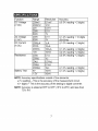
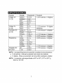
Function
Range Resolution
Accuracy
DCVoltage 200mV 0.1mY +(0.5% reading
2000mV1mV
(VDC)
20V
0.01V
200V 0.1V
600V 1V
ACVoltage 200V 0.1V
+(1.2% reading
600V 1V
(VAC)
(50/60Hz)
DCCurrent 2000#A 1#A
+(1.0% reading
(ADC)
20mA 10pA
200mA 100pA +(1.2% reading
10A
10mA
+(2.0% reading
Resistance 200£2 0.1£2
+(0.8% reading
2000£2 1£2
20k£! 0.01
k£!
200k£! 0.1k£!
2000k£! 1k£!
+(1.0% reading
10mV
Battery
Test 9V
+(1.0% reading
1.5V
10mV
+ 2 digits)
+ 10 digits
+ 2 digits)
+ 2 digits)
+ 2 digits)
+ 2 digits)
+ 2 digits)
+ 2 digits)
NOTE: Accuracy specifications consist of two elements:
• (% reading) - This is the accuracy of the measurement circuit.
• (+ digits) - This is the accuracy of the analog to digital converter.
NOTE: Accuracy is stated at 65°F to 83°F (18°C to 28°C) and less than
75% RH.
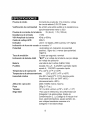
Diode
Test
Continuity
Check
Test current of 1 mA maximum,
open circuit
voltage 2.8V DC typical
Audible signal will sound if the resistance is
Input Impedance
ACV Bandwidth
less than approximately
30£2
9V (6mA); 1.5V (100mA)
>IM_
45Hz to 450Hz
DCA voltage
200mV
Battery
Test current
Display
Overrange
drop
indication
Polarity
Measurement
Rate
Low Battery
Indication
Battery
Fuses
Operating
Operating
Weight
Size
Safety
LCD, 0.5" digits
Automatic
(no indication for positive
Minus (-) sign for negative polarity.
2 times per second, nominal
polarity);
"BAT"
is displayed if battery voltage
below operating voltage
one 9 volt (NEDA 1604) battery
drops
mA, pA ranges; 0.2A/250V fast blow
A range; 10A/250V fast blow
Temperature
Storage Temperature
Operating
Humidity
Storage
3 ½ digit, 2000 count
"1" is displayed
Humidity
Altitude
41°F to 104°F (5°C to 40°C)
-4°F to 140°F (-20°C to 60°C)
Max 80% up to 87°F (31°C) decreasing
to 50% at 104°F (40°C)
<80%
7000ft.
(2000)
meters
linearly
maximum.
9.17 oz. (260g).
4.78" x 2.38" x 1.57" (121.5mm x 60.6mm
40mm)
For indoor use and in accordance
with
x
Overvoltage
Category II, Pollution Degree 2.
Category II includes local level, appliance,
portable equipment,
etc., with transient
overvoltages
less than Overvoltage
Category
Ill.
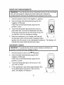
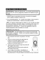
i WARNING:
To avoid
electric
shock,the
disconnect
the test leads from any
source of voltage
before
removing
battery door.
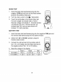
1.
2.
II
Disconnect the test leads from the meter.
Remove the protective rubber holster (if installed).--_._
3.
Open the battery door by loosening the screw using a
Phillips head screwdriver.
4.
Insert the battery into battery holder, observing the
correct polarity.
Put the battery door back in place. Secure with the
screw.
i WARNING:
battery door To
is inavoid
placeelectric
and fastened
shock, do
securely.
not operate the meter until the
NOTE: If your meter does not work properly, check the fuses and batteries
to make sure that they are still good and that they are properly inserted.
II
e] ".,l=1t.,f-I III _JellI__."11
IIt.|l[_l i [e] __
I
J WARNING:
are very dangerous
Risk of electrocution.
and should be High-voltage
measured with
circuits,
great both
care. AC and DC, J
1. ALWAYS turn the function switch to the OFF position when the meter is
not in use.
2. If "OL" appears in the display during a measurement, the value exceeds
the range you have selected. Change to a higher range.
NOTE: On some low AC and DC voltage ranges, with the test leads not
connected to a device, the display may show a random, changing reading.
This is normal and is caused by the high-input sensitivity. The reading will
stabilize and give a proper measurement when connected to a circuit.
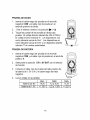
DC VOLTAGE MEASUREMENTS
being switched ON or OFF. Large voltage surges may occur that can
J damage
AUTION:
not measure DC voltages if a motor on the circuit is
the Do
meter.
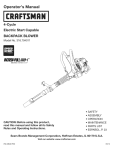
1.
Set the function switch to the highest V DC
position
_---
2.
Insert the black test lead banana plug into the
negative (COM) jack.
Insert the red test lead banana plug into the
positive (V) jack.
Touch the black test probe tip to the negative side
of the circuit.
_
3.
Touch the red test probe tip to the positive side of
the circuit.
4.
I
•................
_')i,
_/i
/_j _t'_/.
.......
Read the voltage in the display. Reset the
function switch to successively lower V DC
positions to obtain a higher resolution reading.
The display will indicate the proper decimal point and value. If the
polarity is reversed, the display will show (-) minus before the value.
10
I
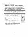
AC VOLTAGE MEASUREMENTS
WARNING: Risk of Electrocution. The probe tips may not be long
enough to contact the live parts inside some 240V outlets for
appliances because the contacts are recessed deep in the outlets. As
a result, the reading may show 0 volts when the outlet actually has
voltage on it. Make sure the probe tips are touching the metal contacts
inside the outlet before assuming that no voltage is present.
I
being switched ON or OFF. Large voltage surges may occur that can
AUTION: Do not measure AC voltages if a motor on the circuit is
damage the meter.
1.
Set the function switch to the highest V AC position.
2.
Insert the black test lead banana plug into the
negative (COM) jack.
Insert red test lead banana plug into the positive (V)
jack.
3.
Touch the black test probe tip to the negative side of
the circuit.
Touch the red test probe tip to the positive side of
the circuit.
4.
Read the voltage in the display. Reset the function
switch to successively lower V AC positions to obtain
a higher resolution reading. The display will indicate
the proper decimal point and value.
11
I
I
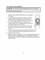
DC CURRENT MEASUREMENTS
longer than 30 seconds. Exceeding 30 seconds may cause damage to
I the
CAUTION:
Do not
current measurements on the 10A scale for
meter and/or
themake
test leads.
1.
Insert the black test lead banana plug into the negative
(COM) jack.
2.
For current measurements up to 200mA DC, set the
function switch to the highest DC mA position and
insert the red test lead banana plug into the (mA) jack.
For current measurements up to 10A DC, set the
function switch to the 10A range and insert the red test
lead banana plug into the (10A)jack.
4.
Remove power from the circuit under test, then open
up the circuit at the point where you wish to measure
current.
5.
Touch the black test probe tip to the negative side of the circuit.
Touch the red test probe tip to the positive side of the circuit.
6.
Apply power to the circuit.
7.
Read the current in the display. For mA DC measurements, reset the
function switch to successively lower mA DC positions to obtain a
higher resolution reading. The display will indicate the proper decimal
point and value.
12
I
RESISTANCE
I
MEASUREMENTS
test and discharge all capacitors before taking any resistance
ARNING: To avoid electric shock, disconnect power to the unit under
measurements. Remove the batteries and unplug the line cords.
1.
Set the function switch to the highest £2 position.
2.
Insert the black test lead banana plug into the
negative (COM) jack
Insert the red test lead banana plug into the
positive £2jack.
3.
Touch the test probe tips across the circuit or
part under test. It is best to disconnect one side
of the part under test so the rest of the circuit will
not interfere with the resistance reading.
4.
Read the resistance in the display and then set
the function switch to the lowest £2position that is
greater than the actual or any anticipated resistance.
indicate the proper decimal point and value.
CONTINUITY
I
The display will
CHECK
I circuits
ARNING:
To avoid
electric
shock,
or wires
that have
voltage
on never
them. measure continuity on
1.
Set the function switch to the _ °)))position.
2.
Insert the black lead banana plug into the
negative (COM) jack
Insert the red test lead banana plug into the
positive (£2)jack.
3.
Touch the test probe tips to the circuit or wire
you wish to check.
4.
If the resistance is less than approximately 30£2,
the audible signal will sound. If the circuit is
open, the display will indicate "1".
13
I
DIODE
TEST
1. Insert
theblack
testleadbanana
plugintothe
negative
COM
jackandtheredtestleadbanana
plugintothepositive
diode
jack.
2. Turn
therotary
switch
tothe_ / o))) position.
3.
Touch the test probes to the diode under test.
Forward voltage will indicate 400 to 700mV.
Reverse voltage will indicate "r'. Shorted devices
will indicate near 0mV. Shorted devices will
indicate near 0mV and an open device will
indicate "r' in both polarities.
BATTERY TEST
1.
Insert the black test lead banana plug into the negative COM jack and
the red test lead banana plug into the positive V jack.
2.
Select the 1.5V or 9V BAT position using the
function select switch.
3.
Connect the red test lead to the positive side of
the 1.5V or 9V battery and the black test lead to
the negative side of the 1.5V or 9V battery.
4.
Read the voltage in the display.
9V battery:
1.5V battery:
Good
Weak
Bad
>8.2V
>1.35V
7.2 to 8.2V
1.22 to 1.35V
<7.2V
<1.22V
14
ofvoltage
before
removing
the
back
cover
orthe
orfuse
I source
WARNING:
electric
shock,
disconnect
the
testbattery
leads
from
any
doors. Toavoid
I WARNING:
Toavoid
eare
lectric
shock,
operate
yourmeter
until
the
battery
andfuse
doors
inplace
adonot
ndfastened
securely.
ThisMultiMeter
isdesigned
toprovide
years
ofdependable
service,
ifthe
following
careinstructions
areperformed:
1. KEEP
THEMETER
DRY.
Ifitgetswet,wipeitoff.
2. USE AND STORE THE METER IN NORMAL TEMPERATURES.
Temperature extremes can shorten the life of the electronic parts and
distort or melt plastic parts.
3.
HANDLE THE METER GENTLY AND CAREFULLY.
damage the electronic parts or the case.
4.
KEEP THE METER CLEAN. Wipe the case occasionally with a damp
cloth. DO NOT use chemicals, cleaning solvents, or detergents.
5.
USE ONLY FRESH BATTERIES OF THE RECOMMENDED
SIZE
AND TYPE. Remove old or weak batteries so they do not leak and
damage the unit.
6.
IF THE METER IS TO BE STORED FOR A LONG PERIOD OF TIME,
the batteries should be removed to prevent damage to the unit.
15
Dropping it can
I
I
REPLACING THE BATTERIES
I
l WARNING:
To avoid
electric
shock,thedisconnect
the test leads from any
source of voltage
before
removing
battery door.
1.
2.
3.
When the batteries become exhausted or drop below the operating
voltage, "BAT" will appear in the right-hand side of the LCD display.
The batteries should be replaced.
Follow instructions for installing batteries. See the Battery Installation
section of this manual.
Dispose of the old batteries properly.
I WARNING:
shock, do
not operate your meter until the
battery door To
is inavoid
placeelectric
and fastened
securely.
1
REPLACING THE FUSES
l source
WARNING:
of voltage
To avoid
before
electric
removing
shock,the
disconnect
fuse door.the test leads from any
1.
2.
3.
Disconnect the test leads from the meter and any item under test.
Remove the protective rubber holster.
Open the fuse door by loosening the screw on the door using a Phillips
head screwdriver.
4.
Remove the old fuse from its holder by gently pulling it out.
Install the new fuse into the holder.
5.
6.
1
Always use a fuse of the proper size and value (0.2A/250V fast blow
for the 200mA range, 10A/250V fast blow for the 10A range).
Put the fuse door back in place. Insert the screw and tighten it securely.
WARNING:
fuse
door is in
To place
avoid and
electric
fastened
shock,securely.
do not operate your meter until the
|
UL LISTED
The UL mark does not indicate that this product has been evaluated for the
accuracy of its readings.
16
I
I/ _,{olUJ;] III:(_,,1:[olO]l i I_[_
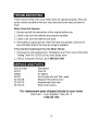
There may be times when your meter does not operate properly. Here are
some common problems that you may have and some easy solutions to
them.
Meter Does Not Operate:
1. Always read all the instructions in this manual before use.
2. Check to be sure the batteries are properly installed.
3. Check to be sure the batteries are good.
4. If the battery is good and the meter still does not operate, check to be
sure that both ends of the fuse are properly installed.
If You Do Not Understand
1. Purchase the instructional
How the Meter Works:
book "Multitesters
and Their Use for Electrical
Testing" (Item No. 82303) at your local Sears store.
2. Call our Customer Service Line 1-888-326-1006.
Item Number
82374
93894
82378
Description
Fuse kit
9V battery
Set of black and red Test Leads
82140-DB
82140-DF
82140-CS
Replacement battery door
Replacement fuse door
Rear cover screws
For replacement parts shipped directly to your home
Call 9 am - 5 pm Eastern Time, M - F
1-888-326-1006
17
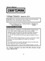
Owner's Manual
CRAFTSMAN
Voltage Detector
Model
No. 82174
in this understand
manual before
product.
I Instructions
AUTION: Read,
and using
follow this
Safety
Rules and Operating
© Sears, Roebuck and Co., Hoffman
www.craftsman.com
Estates,
IL 60179 U.S.A.
022205
;ILvA=lb'd=f,_!:| =1II IllVlvg,_t:1 :;,_t_ I &_
FIVE YEAR FULL WARRANTY ON CRAFTSMAN Voltage Detector.
If this CRAFTSMAN Voltage Detector fails to give complete
satisfaction within five years from the date of purchase, RETURN IT
TO THE NEAREST SEARS STORE OR OTHER CRAFTSMAN
OUTLET IN THE UNITED STATES, and Sears will replace it, free of
charge.
If this CRAFTSMAN Voltage Detector is used for commercial
purposes, this warranty applies for 90 days from the date of
purchase.
or rental
This warranty gives you specific legal rights, and you may also have
other rights which vary from state to state
Sears Roebuck andCo
Debt 817WA Hoffman Estates IL60179
For Customer
Assistance
Friday 1-888-326-1006
Call 9am-5
18
PM (EST),
Monday
through
I
WARNING:
USE EXTREME
CAUTION IN THE USE OF THIS
DEVICE. Improper use of this device can result in injury or death.
Follow all safeguards suggested in this manual in addition to the
normal safety precautions used in working with electrical circuits. DO
NOT service this device if you are not qualified to do so.
.'['_!_1=11
Ib'dl,."]i'd
_v_
I:][e] I_
This symbol adjacent to another symbol, terminal or
operating device indicates that the operator must refer to
an explanation in the Operating Instructions to avoid
personal injury or damage to the Voltage Detector.
WARNING
WARNING
indicates
a potentially
hazardous
I This
situation,
which ifsymbol
not avoided,
could
result in death
or
serious injury.
CAUTION I1 This CAUTION symbol indicates a potentially hazardous
situation, which if not avoided, may result in damage to the
Voltage Detector.
FDI
throughout
double insulation
or reinforced
This symbol byindicates
that a device
is protectedinsulation.
UL LISTED
The UL mark does not indicate that this product has been evaluated for the
accuracy of its readings.
19
Voltage
Sensitivity
100 to 240V AC
Frequency
Detection distance
50/60Hz
Over voltage
Category III 600V
Operating
32 to 122°F (0 to 50°C)
Storage
Temperature
Temperature
Humidity
Altitude
<0.2"
-4 to 140°F (-20 to 60°C)
<85%RH
Battery
<2000 meters (6561 feet)
2 AAA batteries
Dimensions/Weight
6x0.75x1 inches / 2oz
Safety
For indoor use and in accordance with
Overvoltage
Category III, Pollution Degree 2.
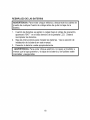
:T,_llllll =lt.¥dl I __.']lIF,_1
IIIIF,_llII [e] _ I
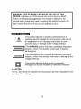
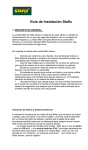
6.
Open the battery door (end cap) by gently
prying up/out at the pocket clip using a small
screwdriver.
7.
Insert two AAA batteries (observe polarity).
8.
Replace the battery door.
NOTE: If your meter does not work properly,
check the battery to make sure that it still
good and that it is properly inserted.
20
End cap
Removal
for battery
replacement
/ I
......
I
cover is in place and fastened securely.
I battery
WARNING:
Toavoid
electric
shock,
donotoperate
themeter
untilthe
WARNING: Risk of Electrocution. High-voltage circuits, both AC and
DC, are very dangerous and should be measured with great care.
I
I
AC VOLTAGE DETECTION
WARNING: Risk of Electrocution. Before using to check for voltage in
an outlet, always test the Voltage Detector on a known live circuit to
verify that the Voltage Detector is working properly.
!
of
the probe Risk
and away
from the probe
WARNING:
of Electrocution.
Keeptiphands and fingers on the body
I
To check for the presence of AC electrical voltage in an outlet:
1.
Touch the probe tip to a cord plugged into the outlet, or insert the probe
tip into all the outlet holes.
2.
IfAC electrical voltage is present, the detector light will flash and the
audible warning will sound.
NOTE: Random beeps and flashes due to detection of static charges are
normal. Detection of "live" conductors will produce a steady flash
and beep.
21
I
Manual del propietario
Multimetro
Modelo
Detector
Modelo
Digital
No. 82140
de voltaje
No. 82174
PRECAUCION:
Lea, comprenda y
siga las Reglas Seguridad e
Instrucciones de operaci6n en este
manual antes de usar el producto.
•
•
•
•
Seguridad
Operaci6n
Mantenimiento
Espafiol
© Sears, Roebuck and Co., Hoffman Estates, IL 60179 U.S.A.
www.sears.com/craftsman
070606
Ir:1:] IIr:l e]:l[o_o]_III1:1_IIeIq
Pagina
3
Garantia
Instrucciones
de Seguridad
4
Sefiales de Seguridad
5
Control y Conectores
6
Simbolos
y Anunciadores
6
Especificaciones
Instalaci6n de la Bateria
7
Instrucciones
10
de operaci6n
9
Medici6n de Voltaje CD
10
Medici6n de Voltaje CA
Medici6n de corriente CD
11
Medidas de resistencia
13
VerMcaci6n de Continuidad
13
Prueba de Diodo
14
Prueba de Bateria
14
Mantenimiento
15
Reemplazo
de Baterias
16
Reemplazo
de los fusibles
17
12
Soluci6n de problemas
18
Servicio y Repuestos
Modelo 82174
18
19
_____ _
__
o_A"
__
"o_
__ h. o
GARANTiA COMPLETA POR UN ANO PARA EL MULiMETRO
ESCALA MANUAL DE CRAFTSMAN
Si este Multimetro
de escala manual CRAFTSMAN
DE
no le satisface
totalmente dentro de un a_o a partir de la fecha de compra,
REGR#:SELO A LA TIENDA SEARS O DISTRIBUIDOR CRAFTSMAN
M/_,S CERCANO EN LOS ESTADOS UNIDOS, y Sears Io reemplazara,
sin cargos.
Si este Multimetro de escala manual CRAFTSMAN
es utilizado de
manera comercial o para renta, esta garantia se aplica a los primeros
90 dias a partir de la fecha de compra.
Esta garantia la otorga derechos legales especificos, ademas de que
usted pueda tener otros derechos variables entre estados
Sears, Roebuck and Co., Dept. 817 WA, Hoffman Estates, IL 60179
Para ayuda al cliente Ilame entre 9 a.m. y 5 PM (EST).
Lunes a viernes 1-888-326-1006
I ADVERTENCIA:
EXTREME SUS PRECAUCIONES
AL USAR ESTE
DISPOSITIVO.
El uso inapropiado de este dispositivo puede causar
lesiones o la muerte. Siga todas las salvaguardas sugeridas en este
manual. Ademas de las precauciones de seguridad normales usadas al
trabajar con circuitos electricos. NO de servicio a este dispositivo si
usted no esta calificado para hacerlo.
Este medidor ha sido disefiado para uso seguro, sin embargo debe ser
operado con precauci6n. Para una operaci6n segura, debera cumplir las
reglas enumeradas a continuaci6n.
1.
NUNCA aplique al medidor voltaje o corriente que exceda los limites
maximos especMcados de alimentaci6n:
Funci6n
VCA
V CD o V CA
mA CD
A CD
Resistencia,
Continuidad
Limites de entrada
Entrada maxima
600V CD/CA
600V CD/CA, 200Vrms en la escala 200mV
200mA 250V fusible de acci6n rapida
10A 250V fusible de acci6n rapida (30
segundos max cada 15 minutos)
250Vrms durante 15seg max
2.
EXTREME
SUS PRECAUCIONES
al trabajar con alta tensi6n.
3.
NO mida voltajes si el voltaje en el enchufe de entrada "COM" excede
500V sobre tierra fisica.
4.
NUNCA conecte los cables del medidor a una fuente de voltaje
cuando el selector de funci6n este en modo de corriente, resistencia
o diodo. Hacerlo puede dafiar al medidor.
5.
SlEMPRE descargue los filtros capacitores en las fuentes de tensi6n
y desconecte la energia al realizar pruebas de diodo o de resistencia.
6.
SlEMPRE apague la tensi6n y desconecte los cables de prueba
antes de abrir la tapa para reemplazar las baterias o fusibles.
7.
NUNCA opere el medidor a menos que la tapa posterior y la tapa de
la bateria y de fusibles esten colocadas y aseguradas.
;']:1_r:11:_"!J]:1."]:[rltJ _11J7:1,
Esta seSal adyacente a otra seSal, terminal o
dispositivo en operaci6n indica que el operador
debera buscar una explicaci6n en las Instrucciones
de operaci6n para evitar lesiones a su persona o
daSos al medidor.
L ADVERTENCIA
]
I
I
RECAUCION
r
m
m
500V
Esta seSal de ADVERTENClA
indica que existe
una condici6n potencialmente peligrosa, que si no
se evita, podria resultar en la muerte o lesiones
graves.
Esta seSal de PRECAUClON indica que existe una
condici6n potencialmente peligrosa, que si no se
evita, podria resultar en daSos al producto.
Esta seSal advierte al usuario de que la(s)
terminal(es) asi marcadas no deberan ser
conectadas a un punto del circuito donde el voltaje
con respecto a tierra fisica exceda (en este caso)
500 VCA o VCD.
Esta seSal adyacente a una o mas terminales las
identifica como asociadas con escalas que pueden,
bajo uso normal, estar sujetas a voltajes
particularmente peligrosos. Para maxima
seguridad, no debera manipular el medidor y sus
cables de prueba cuando estas terminales esten
energizadas.
Esta seSal indica que un dispositivo esta
completamente protegido mediante doble aislante o
aislamiento reforzado.
_o] _II/ _,To]III:F:i'lo_o] _I:[O,]lI[O]_,,1
:F:
1
Pantalla LCD
2
Selector de FunciSn
3
Enchufe COM
4
Enchufe 10A
5
Enchufe positivo
m
m
Nota: El soporte inclinado, y el
compartimiento
del fusible y bateria se encuentran
parte
posterior de la unidad
m
en la
_ _vA
I:[o]Ko_.',]1:111
_IJ][__,IJIo]_,,1
:[_
•)))
Continuidad
"_
Prueba de diodo
p
micro (amperios)
m
k
£_
milli ( volts, amperios)
kilo (ohms)
ohms
VCD
voltios corriente directa
VCA
voltios corriente alterna
ACD
BAT
amperios corriente directa
Prueba de Bateria
4-5--
_".)-..,1
=[e,]I _1[___[e,]
[e] _I_
Funci6n
Voltaje CD
(V CD)
Voltaje CA
(V CA)
Corriente CD
(A CD)
Resistencia
PRUEBA DE
BATERiA
Escala
200mY
2000mY
20V
200V
600V
200V
600V
Resoluci6n
0.1mY
1mY
0.01V
0.1V
1V
0.1V
1V
2000p A
20mA
200mA
lpA
10pA
10A
200£2
100p A
10mA
0.1£2
2000£2
20k£!
200k£!
1£2
0.01 k£!
0.1k£!
2000k£!
9V
lk£!
10mV
1.5V
10mV
Precisi6n
+ (0.5% lectura + 2 digitos)
+ (1.2% lectura + 10 digitos
(50/60Hz)
+ (1.0% lectura + 2 digitos)
± (1.2% lectura + 2 digitos)
± (2.0%lectura
+ 2 digitos)
± (0.8%lectura
+ 2 digitos)
± (1.0% lectura + 2 digitos)
± (1.0% lectura + 2 digitos)
NOTA: Las especificaciones de precisi6n consisten de dos elementos:
• (% de lectura) - Esta es la precisi6n del circuito de medici6n.
• (+ digitos) - Esta es la precisi6n del convertidor anal6gico a digital.
NOTA:
La precisi6n esta especificada
menor a 75% RH.
a 65°F a 83°F (18°C a 28°C) y
_-,.)_ =[e,]I _1[e,7'__T_e,]
[el ZI=[_.".)
Prueba
de diodo
Verificaci6n
Prueba
de continuidad
de corriente
Impedancia
Corriente de prueba de 1 mA m&xima, voltaje
de circuito abierto 2.8V DC tipica
Se emitira una sepal audible si la resistencia es
aproximadamente
de la bateria
9V (6mA);
de entrada
>1MO
VCA Amplitud
de banda
Caida de voltaje ACD
45Hz a 450Hz
200mY
Indicador
Indicaci6n
LCD 3 1/2 digitos,
se muestra "1"
de fuera
de escala
Polaridad
2000 cuentas,
0.5" digitos
Autom&tica
(sin indicacion de polaridad
positiva);
Signo de (-) menos para polaridad
negativa.
Tasa de medici6n
Indicaci6n
de bateria
d6bil
Bateria
Fusibles
Temperatura
Temperatura
Humedad
Altitud
Peso
menor a 30_(-2
1.5V (100mA)
de operaci6n
de almacenamiento
relativa
de operaci6n
2 veces pot segundo, nominal
"BAT"
si el voltaje de la bateria
del voltaje de operaci6n
cae pot debajo
una bateria de 9 voltios (NEDA 1604)
escalas mA, pA ; 0.2A/250V quemado
escala A; 10A/250V quemado r&pido
5°C a 4O°C (41°F a 104°F)
rapido
-20°C a 60°C (-4°F a 140°F)
Max 80% hasta 87°F (31°C) disminuyendo
linealmente
a 50% en 104°F (40°C)
(almacenamiento
<80%)
2000 (7000ft) metros
260g (9.17 oz.).
maxima.
TamaSo
121.5 x 60.6 x 40mm
(4.78"
Seguridad
Para uso en interiores y de conformidad
con
Categoria
II de sobrevoltaje,
Grado de
Contaminacion
2. La Categoria II incluye nivel
local, electrodomesticos,
equipo portatil, etc.,
con voltajes transitorios
menores a la
Categoria
III de Sobrevoltaje.
x 2.38" x 1.57")
I
prueba de cualquier fuente de voltaje antes de quitar la tapa de la
J ADVERTENClA:
Para evitar choque electrico, desconecte los cables de J
bateria.
1.
Desconecte
2.
Quite la funda protectora de hule.
los cables de prueba del medidor.
3.
Abra la tapa de la bateria aflojando el tomillo con un
destomillador cabeza Phillips.
4.
Inserte la bateria en el soporte, observando
polaridad correcta.
5.
Coloque la tapa de la bateria en su lugar.
con el tornillo.
la
Asegure
J ADVERTENClA:
hasta que la tapa de
Para
la bateria
evitar choque
este colocada
electrico,y asegurada.
no opere el medidor
NOTA: Si su medidor no funciona apropiadamente, revise los fusibles y la
bateria para asegurar que estan en buenas condiciones y que estan
correctamente instalados.
k,
_
Ok,
|
O"
___
Ok,
tanto de CA y CD, son muy peligrosos y deberan ser medidos con gran
I ADVERTENClA:
Riesgo de electrocuci6n.
Los circuitos de alta tensi6n,
cuidado.
1. SIEMPRE gire el conmutador de funci6n a la posici6n de apagado
(OFF) cuando el medidor no este en uso.
2. Si en la pantalla aparece" OL" durante una medida, el valor excede la
escala que ha seleccionado.
Cambie a una escala mas alta.
NOTA: En algunas escalas bajas de voltaje CA y CD, sin estar los cables
de prueba conectados a dispositivo alguno, la pantalla puede mostrar una
lectura aleatoria cambiante. Esto es normal yes causado por la alta
sensibilidad de la alimentaci6n.
La lectura se estabilizara y dara una
medida apropiada al estar conectada a un circuito.
MEDIClON
I
DE VOLTAJE
CD
encendiendo y apagando. Pueden ocurrir grandes oleadas de voltaje
RECAUClON:
No mida voltajes CD si un motor en el circuito esta
que dafiarian al medidor.
1.
Fije el selector de funci6n a la posici6n V CD mas
alta.
2.
Inserte el conector banana del cable negro de
prueba en el enchufe negativo (COM).
Inserte el conector banana del cable rojo de
prueba en el enchufe positivo (V).
3.
Toque la punta de la sonda negra de prueba del
lado negativo del circuito.
Toque la punta de la sonda roja de prueba del
lado positivo del circuito.
4.
Lea el voltaje en la pantalla. Reestablezca el
selector de funci6n para disminuir sucesivamente
las posiciones de V CD para obtener una lectura de mayor resoluci6n.
10
I
Lapantalla
indicara
elvalor
ypunto
decimal
correcto.
Siseinvierte
la
polaridad,
lapantalla
indicara
(-)menos
antes
delvalor.
MEDIClON
DEVOLTAJE
CA
ADVERTENClA:
Riesgo
deelectrocuci6n.
Laspuntas
delassondas
pueden
noserIosuficientemente
largas
para
hacer
contacto
conlas
partes
vivas
dentro
dealgunos
contactos
240V
para
electrodomesticos
debido
aquedichos
contactos
estan
muyadentro
delcontacto.
Como
resultado,
lalectura
puede
indicar
0voltios
cuando
enrealidad
el
contacto
sitiene
tensi6n.
Verifique
quelaspuntas
delassondas
estan
tocando
loscontactos
metalicos
dentro
delcontacto
antes
deasumir
quenohaytensi6n.
encendiendo
yapagando.
Pueden
ocurrir
grandes
oleadas
de
I esta
PRECAUClON:
No
mida
voltajes
CAsialgQn
motor
enelcircuito
voltaje
quedaSarian
almedidor.
1.
Fije el selector de funci6n a la posici6n V CA mas
J
2.
alta.
Inserte el conector banana del cable negro de
prueba en el enchufe negativo (COM).
Inserte el conector banana del cable rojo de prueba
en el enchufe positivo (V).
f ............................
i]]'i
_.......................
_ [!
_"_,!'l
- ........
3.
Toque la punta de la sonda negra de prueba del
lado negativo eel circuito.
Toque la punta de la sonda roja de prueba del lado
positivo del circuito.
4.
Lea el voltaje en la pantalla. Reestablezca el
selector de funci6n para disminuir sucesivamente
las posiciones de V CA para obtener una lectura de mayor resoluci6n.
La pantalla indicara el valor y punto decimal correcto.
11
._.,_.._ -,
_,_=_)ji{
i
MEDICION
DE CORRIENTE
CD
PRECAUCION: no haga mediciones de corriente en la escala de 10 A
durante mas de 15 segundos. Si la medici6n se extiende a mas de 15
segundos el multimetro y!o los conductores de prueba podrian sufrir
daSos.
1.
Inserte el conector banana del cable negro de prueba
en el enchufe negativo (COM).
2.
Para medici6n de corriente hasta 200mA CD, fije el
selector de funci6n en la posici6n CD mAmas alta e
inserte el conector banana del cable rojo de prueba en
el enchufe (mA).
3.
Para medici6n de corriente hasta 1A CD, fije el
selector de funci6n en la escala 10A mas alta e inserte
el conector banana del cable rojo de prueba en el
enchufe (10A).
4,
Corte la tensi6n del circuito bajo prueba
enseguida abra el circuito en el punto donde desea medir la corriente.
5.
Toque la punta de la sonda negra de prueba del lado negativo del
circuito.
/};
Toque la punta de la sonda roja de prueba del lado positivo del
circuito.
6.
Aplique tensi6n al circuito.
7.
Lea la corriente en la pantalla. Para medidas mA CD, reestablezca el
selector de funci6n para disminuir sucesivamente las posiciones de
mA CD para obtener una lectura de mayor resoluci6n. La pantalla
indicara el valor y punto decimal correcto.
12
MEDIDAS DE RESISTENCIA
ADVERTENCIA:
Para evitar choque electrico, desconecte la tensi6n
a la unidad bajo prueba y descargue todos los capacitores antes de
tomar cualquier medici6n de resistencia. Retire las baterias y
desconecte los cordones de linea.
1.
Fije el selector de funci6n a la posici6n £_ mas alta.
2.
Inserte el conector banana del cable negro de
prueba en el enchufe negativo (COM).
Inserte el conector banana del cable rojo de prueba
en el enchufe positivo £_.
3.
Toque las puntas de las sondas a traves del circuito
o parte bajo prueba. Es mejor desconectar un lado
de la pieza bajo prueba para que el resto del circuito
no interfiera con la lectura de resistencia.
4.
Lea el voltaje en la pantalla y enseguida fije el selector de funci6n en la
posici6n £_ mas baja que sea mayor la resistencia actual o cualquiera
anticipada. La pantalla indicara el valor y punto decimal correcto.
VERIFICACION
DE CONTINUIDAD
I enDVERTENClA:
Para evitar
choquevoltaje.
electrico, nunca mida continuidad
circuitos o alambres
que tengan
1.
Fije el selector de funci6n en la "_°))_ posici6n.
2.
Inserte el conector banana del cable negro de
prueba en el enchufe negativo (COM).
Inserte el conector banana del cable rojo de prueba
en el enchufe positivo £_.
3.
Toque las puntas de las sondas al circuito o
alambre que desee probar.
4.
Si la resistencia es menor a aproximadamente 30£_,
se emitira una serial audible. Si el circuito esta
abierto, la pantalla indicara "1".
13
PRUEBA
DE DIODO
1,
2.
3.
Inserte el cable negro de prueba en el enchufe
negativo COM y el cable rojo de prueba en el
enchufe positivo de diodo.
Gire el selector rotativo a la posici6n _1- / o))).
Toque las puntas de las sondas al diodo bajo
prueba. El voltaje directo indicara de 400 a 700mV.
El voltaje inverso indicara 'T'. Los dispositivos con
corto indicaran cerca de 0mV. Los dispositivos en
corto indicaran cerca de 0mV y un dispositivo abierto
indicara "1" en ambas polaridades.
PRUEBA
DE BATERiA
1.
Inserte el cable negro de prueba en el enchufe
negativo COM y el cable rojo de prueba en el enchufe
positivo V.
2.
Seleccione la posici6n 1.5V o 9V BAT con el selector
de funci6n.
3.
Conecte el cable rojo de prueba del lado positivo de
la bateria de 1.5V (5 9V y el cable negro del lado
negativo.
4.
Lea el voltaje en la pantalla.
Bateria de 9V:
Bateria de 1.5V:
Bien
>8.2V
>1.35V
14
Debil
7.2 a 8.2V
1.22 a 1.35V
Mala
<7.2V
<1.22V
rAV:1_ii :1_1hVd
1:1_i I_l
de prueba de cualquier fuente de voltaje antes de quitar la tapa
I ADVERTENClA:
Para evitar choque electrico, desconecte los cables
posterior o la de la bateria o fusibles.
menos que la tapa posterior y la tapa de la bateria y fusibles esten
I colocadas
ADVERTENClA:
Para evitar choque electrico, no opere el medidor a
y aseguradas.
Este multimetro esta diseSado para proveer muchos aSos de servicio
confiable, si se Ilevan a cabo las siguientes instrucciones de cuidado del
manual:
1.
2.
MANTENGA SECO EL MEDIDOR. Si se moja, sequelo.
USE Y ALMACENE EL MEDIDOR BAJO TEMPERATURA
NORMAL.
5.
Los extremos de temperatura pueden acortar la vida de las partes
electr6nicas y distorsionar o fundir las piezas de plastico.
MANIPULE EL MEDIDOR CON SUAVlDAD Y CUlDADO. Dejarlo
caer puede daSar las partes electr6nicas o la caja.
MANTENGAEL MEDIDOR LIMPIO. Ocasionalmente limpie la caja
con un paso hQmedo. NO use quimicos, solventes para limpieza o
detergentes.
USE SOLO BATERIAS NUEVAS DEL TAMANO Y TIPO
6.
RECOMENDADO.
Retire las baterias viejas o debiles de manera que
no se derramen y da_en la unidad.
SI SE VA A ALMACENAR EL MEDIDOR DURANTE UN LARGO
3.
4.
PERIODO DE TIEMPO, debera retirar la bateria para prevenir da_os a
la unidad.
15
I
I
REEMPLAZO
DE LAS BATERiAS
prueba de cualquier fuente de voltaje antes de quitar la tapa de la
I bateria.
DVERTENCIA: Para evitar choque electrico, desconecte los cables de
1.
2.
3.
Cuando las baterias se agoten o caigan bajo el voltaje de operaci6n,
aparecera "BAT" en el lado derecho de la pantalla LCD. Debera
reemplazar las baterias.
Siga las instrucciones para instalar las baterias. Vea la secci6n de
instalaci6n de la bateria en este manual.
Deseche la bateria usada apropiadamente.
menos que la tapa posterior y la tapa de la bateria y de fusibles esten
I colocadas
ADVERTENClA:
Para evitar choque electrico, no opere el medidor a
y aseguradas.
16
I
REEMPLAZO
DE LOS FUSIBLES
de prueba de cualquier fuente de voltaje antes de quitar la tapa de
I fusibles.
ADVERTENCIA: Para evitar choque electrico, desconecte los cables
1.
Desconecte
prueba.
2.
3.
Quite la funda protectora de hule.
Abra la tapa de la bateria aflojando el tornillo con un destornillador
cabeza Phillips.
Quite el fusible quemado de su soporte tirando suavemente de el.
Instale el fusible nuevo en el porta fusibles.
Use siempre un fusible de tamaSo y valor apropiado (0.5A/250V de
quemado rapido para la escala 200mA, 10A/250V de quemado rapido
para la escala 10A).
Coloque la tapa del fusible en su lugar. Inserte el tornillo y apriete para
asegurar.
4.
5.
6.
7.
los cables de prueba del medidor y cualquier articulo bajo
menos que la tapa posterior y la tapa de la bateria y fusibles esten
I colocadas
ADVERTENClA:
Para evitar choque electrico, no opere el medidor a
y aseguradas.
INSCRITO EN UL
La marca UL no indica que este producto ha sido evaluado en cuanto a la
precisiSn de sus lecturas.
17
_o] Rt[oKo] _I J]:1 :,1
_,{o]:] 1:1;_r:_:
Habra ocasiones en que su medidor no funcione correctamente.
En
seguida encontrara algunos problemas comunes que puede Ilegar a tenet
y algunas soluciones faciles.
El medidor
no funciona:
1. Siempre lea todas las instrucciones
de este manual antes de usar.
2. Verifique que la bateria esta bien instalada.
3. Verifique que la bateria esta en buenas condiciones.
4. Si la bateria esta en buen estado y el medidor aun no funciona, revise
el fusible para asegurar que ambos extremos esten bien insertados.
Si usted no comprende
c6mo funciona
el medidor:
1. Compre el libro de instrucci6n Multimetros y su uso en las pruebas
electricas ('Multitesters and Their Use for Electrical Testing") (Articulo
No. 82303) en la tienda Sears de su Iocalidad.
2. Llame a nuestra Linea de Servicio al Cliente 1-888-326-1006.
."]=1r,,Lvj
[e][o]b'dlr,,l=l:JuJ=_,."]1
I[O_
NQmero de articulo
82374
93894
82378
82140-DB
82140-DF
82140-CS
Descripci6n
Kit del fusible
Bateria de 9V
Juego de cables de prueba negro y rojo
Tapa de bateria de reemplazo
Tapa de fusible de reemplazo
Tomillos de la tapa posterior
Para piezas de reemplazo embarcadas directamente
a su hogar
Llame de lunes a viernes de 9 a.m. a 5 p.m. hora del este
1-888-326-1006
18
Manual del usuario
N
Detector
de voltaje
ModeloNo.82174
© Sears, Roebuck and Co., Hoffman Estates, IL 60179 U.S.A.
www.sears.com/craftsman
121103
I PRECAUCI6N:
Lea comprenda y cumpla con las Instrucciones
de
I
operaci6n y reglas de seguridad en este manual antes de usar el producto. I
GAP,ANTiA COMPLETA POP, CINCO ANOS en el detector de voltaje
CRAFTSMAN. Si este detector de voltaje CRAFTSMAN no le satisface
totalmente dentro de cinco afios a partir de la fecha de compra,
P,EGP,ESE A LA TIENDA SEARS U OTP,O VENDEDOP, DE
CRAFTSMAN EN LOS ESTADOS UNIDOS, y Sears Io reemplazara sin
cargo.
Si este detector de voltaje CRAFTSMAN es usado con fines comerciales o
para renta, esta garantia es valida durante 90 dias a partir de la fecha de
compra.
Esta garantia le otorga derechos legales especificos, ademas de otros
que pueda usted tener y que varian de estado a estado
Sears, Roebuck and Co., Dept. 817WA, Hoffman Estates, IL 60179
Para asistencia al cliente Llame entre 9 a.m. y 5 p.m. (EST), de lunes a
viernes al 1-888-326-1006
19
ADVERTENCIA:
DISPOSITIVO.
EXTREME
SUS
El uso inadecuado
PRECAUCIONES
de este dispositivo
AL USAR
ESTEI
puede
resultar
en I
lesiones
o la muerte.
Siga las salvaguardas
sugeridas
en este manual,
adem_ls
de las precauciones
normales
usadas
al trabajar
con circuitos
electricos.
NO de servicio
a este dispositivo
si usted
no est_l capacitado
I
I
I
para hacerlo.
I
] =1_r;! ! _-lh] =!-1 =[d.Ul:]Imy;!rail
Este seral, adyacente a otra seral, terminal o dispositivo
de operaci6n indica que el operador debe consultar las
explicaciones en las Instrucciones de operaci6n para
evitar lesiones personales o daros al Detector de voltaje.
indica una situaci6n
I Esta seral de ADVERTENCIA
I ADVERTENClA I potencialmente peligrosa, que si no se evita, podria
resultar en lesiones graves o la muerte.
Esta serial de precauci6n
indica una situaci6n
I PRECAUClC)N II potencialmente peligrosa, que si no se evita, podria
resultar en daros al Detector de voltaje.
Esta seral indica que el dispositivo esta protegido con
aislamiento doble o aislamiento reforzado.
INSCRITO EN UL
La marca UL no indica que la precisi6n de las lecturas de este producto ha
sido evaluada.
20
=[...",]
".,I=[o,,)
I_1[o,T±[o,,)
[o] _I =[.._
Sensibilidad
Frecuencia
100 a 240V CA
de Voltaje
50/60Hz
Distancia de detecci6n
<0.2"
Sobre voltaje
Categoria
III 600V
Temperatura
de operaci6n
0 a 50°C (32 a 122°F)
Temperatura
Humedad
de almacenamiento
-20 a 60°C (-4 a 140°F)
<85%RH
Altitud
<2000 metros (6561 pies)
2 baterias AAA
Bateria
Dimensiones/Peso
15.25 x 1.9 x 2.54 cm, 057 g
(6x0.75x1 pulg. / 2oz)
Seguridad
Para uso en interiores y de
conformidad con la Categoria
sobrevoltaje, Grado de
contaminaci6n 2.
__
__
e_
=
__ _ __
t,
III de
__
6.
Quite el tap6n de la bateria estirando
suavemente hacia arriba sobre el clip de bolsillo
con un destornillador pequeSo.
7.
Inserte dos baterias AAA (observe la polaridad).
8.
Reemplace el tap6n de la bateria.
AVISO: Si su medidor no funciona correctamente,
revise la condici6n de las baterias y si estan
insertadas correctamente.
21
4'4,
Quitar tapon
del extremo _
superior par_
reemplazar
la bateria
I
que
la tapa de la bateria
esta choque
colocadaelectrico,
y asegurada.
ADVERTENClA:
Para evitar
no opere el medidor hasta
I
h.
_.
Oh.
II
O"
_._
Oh.
CA y CD, son muy peligrosos y deberan ser medidos con gran
ADVERTENClA:
Riesgo de electrocuci6n. Los circuitos de alto voltaje,
cuidado.
DETECClON
de VOLTAJE CA
el voltaje en un contacto, siempre pruebe el funcionamiento del
ADVERTENClA:
Riesgovivo.
de electrocuci6n. Antes de usar para verificar
Detector en un circuito
ADVERTENClA:
Riesgode de
Mantenga
las manos y
dedos sobre el cuerpo
la electrocuci6n.
sonda y alejados
de la punta
Para verificar la presencia de voltaje electrico CA en un contacto:
1.
Toque la punta de la sonda contra un cord6n enchufado a un contacto
de pared o inserte la sonda en los orificios del contacto.
2.
Si detecta voltaje CA, la luz del detector destellara y emitira un tono
audible de advertencia.
La NOTA: pip pip Aleatorios y destella el descubrimiento debido de cargas
constantes es normal. El descubrimiento de "vive" conductores
produciran un destello y pip pip constantes.
22
I