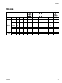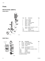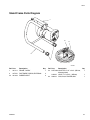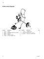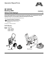
1
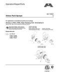
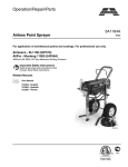
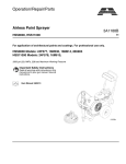
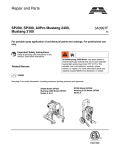
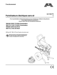
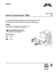
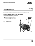
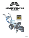
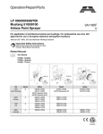
Operation/Repair/Parts MP 400/300 Mustang 4800 Airless Paint Sprayer 332882A EN For portable application of architectural paints and coatings. For professional use only. Not approved for use in European explosive atmosphere locations. 3000 psi (20.7 MPa, 207 bar) Maximum Working Pressure Important Safety Instructions Read all warnings and instructions in this manual and in gun manual. Save all instructions. See page 3 for model information. Related Manuals Gun Manual 312363 - English 312364 - Spanish 312365 - French ti22320a ti22317a Hi-Boy Model Stand Model Contents Contents Models . . . . . . . . . . . . . . . . . . . . . . . . . . . . . . . . . . . 3 Warnings . . . . . . . . . . . . . . . . . . . . . . . . . . . . . . . . . 4 Component Identification . . . . . . . . . . . . . . . . . . . . 8 Operation . . . . . . . . . . . . . . . . . . . . . . . . . . . . . . . . . 9 Grounding . . . . . . . . . . . . . . . . . . . . . . . . . . . . . . 9 Pails . . . . . . . . . . . . . . . . . . . . . . . . . . . . . . . . . 10 Pressure Relief Procedure . . . . . . . . . . . . . . . . 10 Setup . . . . . . . . . . . . . . . . . . . . . . . . . . . . . . . . . 11 Prime and Flush Storage Fluid . . . . . . . . . . . . . 11 Flushing . . . . . . . . . . . . . . . . . . . . . . . . . . . . . . 11 Startup . . . . . . . . . . . . . . . . . . . . . . . . . . . . . . . 12 Clearing Clogs . . . . . . . . . . . . . . . . . . . . . . . . . 13 Adjusting the Pressure . . . . . . . . . . . . . . . . . . . 13 Shutdown . . . . . . . . . . . . . . . . . . . . . . . . . . . . . 13 Storage . . . . . . . . . . . . . . . . . . . . . . . . . . . . . . . 13 Maintenance . . . . . . . . . . . . . . . . . . . . . . . . . . . . . . 14 Daily Maintenance . . . . . . . . . . . . . . . . . . . . . . 14 Electric Motor Maintenance . . . . . . . . . . . . . . . 14 Servicing the Fluid Pump . . . . . . . . . . . . . . . . . 14 Fluid Pump Disconnect . . . . . . . . . . . . . . . . . . . 14 Servicing the Inlet Valve - Hi-Boy . . . . . . . . . . . 16 Servicing the Inlet Valve - Stand . . . . . . . . . . . . 16 Packing Replacement Procedures . . . . . . . . . . 16 Gear and Pump Assembly . . . . . . . . . . . . . . . . 18 Replacement of Electrical Components . . . . . . 19 Troubleshooting . . . . . . . . . . . . . . . . . . . . . . . . . . 20 Parts . . . . . . . . . . . . . . . . . . . . . . . . . . . . . . . . . . . . 22 Manifold Filter (868014) . . . . . . . . . . . . . . . . . . 22 Inlet Valve . . . . . . . . . . . . . . . . . . . . . . . . . . . . . 22 Stand Frame Parts Diagram . . . . . . . . . . . . . . . 23 Hi-Boy Parts Diagram . . . . . . . . . . . . . . . . . . . . 24 Control Parts Diagram . . . . . . . . . . . . . . . . . . . 25 Motor and Drive Parts Diagram . . . . . . . . . . . . 26 Drive Parts . . . . . . . . . . . . . . . . . . . . . . . . . . . . 27 Packing Replacement . . . . . . . . . . . . . . . . . . . . 28 Suction Assemblies . . . . . . . . . . . . . . . . . . . . . . 29 Electrical System . . . . . . . . . . . . . . . . . . . . . . . 30 Technical Data . . . . . . . . . . . . . . . . . . . . . . . . . . . . 31 Airlessco Standard Warranty . . . . . . . . . . . . . . . . 32 2 332882A Models Models Model MP300 MP400 Mustang 4800 332882A Model No. Series Hi-Boy Stand 868058 A x 868050 A x 868051 A 868054 A x 868055 A x 868056 A x 868057 A x 868060 A x 868052 A x 868053 A x x 120V 240V Euro 220V CN 220V LA 220V AP 230V ANZ x x x x x x x x x x 3 Warnings Warnings The following warnings are for the setup, use, grounding, maintenance, and repair of this equipment. The exclamation point symbol alerts you to a general warning and the hazard symbols refer to procedure-specific risks. When these symbols appear in the body of this manual or warning labels, refer back to these Warnings. Product-specific hazard symbols and warnings not covered in this section may appear throughout the body of this manual where applicable. WARNING WARNING GROUNDING This product must be grounded. In the event of an electrical short circuit, grounding reduces the risk of electric shock by providing an escape wire for the electric current. This product is equipped with a cord having a grounding wire with an appropriate grounding plug. The plug must be plugged into an outlet that is properly installed and grounded in accordance with all local codes and ordinances. • Improper installation of the grounding plug is able to result in a risk of electric shock. • When repair or replacement of the cord or plug is required, do not connect the grounding wire to either flat blade terminal. • The wire with insulation having an outer surface that is green with or without yellow stripes is the grounding wire. • Check with a qualified electrician or serviceman when the grounding instructions are not completely understood, or when in doubt as to whether the product is properly grounded. • Do not modify the plug provided; if it does not fit the outlet, have the proper outlet installed by a qualified electrician. • This product is for use on a nominal 120V or 230V circuit and has a grounding plug similar to the plugs illustrated in the figure below. 120V US 230V • Only connect the product to an outlet having the same configuration as the plug. • Do not use an adapter with this product. Extension Cords: • Use only a 3-wire extension cord that has a grounding plug and a grounding receptacle that accepts the plug on the product. • Make sure your extension cord is not damaged. If an extension cord is necessary, use 12 AWG • (2.5 mm2) minimum to carry the current that the product draws. • An undersized cord results in a drop in line voltage and loss of power and overheating. 4 332882A Warnings WARNING WARNING FIRE AND EXPLOSION HAZARD Flammable fumes, such as solvent and paint fumes, in work area can ignite or explode. To help prevent fire and explosion: • Do not spray flammable or combustible materials near an open flame or sources of ignition such as cigarettes, motors, and electrical equipment. • Paint or solvent flowing through the equipment is able to result in static electricity. Static electricity creates a risk of fire or explosion in the presence of paint or solvent fumes. All parts of the spray system, including the pump, hose assembly, spray gun, and objects in and around the spray area shall be properly grounded to protect against static discharge and sparks. Use Graco conductive or grounded high-pressure airless paint sprayer hoses. • Verify that all containers and collection systems are grounded to prevent static discharge. Do not use pail liners unless they are antistatic or conductive. • Connect to a grounded outlet and use grounded extensions cords. Do not use a 3-to-2 adapter. • Do not use a paint or a solvent containing halogenated hydrocarbons. • Keep spray area well-ventilated. Keep a good supply of fresh air moving through the area. Keep pump assembly in a well ventilated area. Do not spray pump assembly. • Do not smoke in the spray area. • Do not operate light switches, engines, or similar spark producing products in the spray area. • Keep area clean and free of paint or solvent containers, rags, and other flammable materials. • Know the contents of the paints and solvents being sprayed. Read all Material Safety Data Sheets (MSDS) and container labels provided with the paints and solvents. Follow the paint and solvents manufacturer’s safety instructions. • Fire extinguisher equipment shall be present and working. • Sprayer generates sparks. When flammable liquid is used in or near the sprayer or for flushing or cleaning, keep sprayer at least 20 feet (6 m) away from explosive vapors. ELECTRIC SHOCK HAZARD This equipment must be grounded. Improper grounding, setup, or usage of the system can cause electric shock. • Turn off and disconnect power cord before servicing equipment. • Use only grounded electrical outlets. • Use only 3-wire extension cords. • Ensure ground prongs are intact on power and extension cords. • Do not expose to rain. Store indoors. 332882A 5 Warnings WARNING WARNING SKIN INJECTION HAZARD High-pressure spray is able to inject toxins into the body and cause serious bodily injury. In the event that injection occurs, get immediate surgical treatment. • Do not aim the gun at, or spray any person or animal. • Keep hands and other body parts away from the discharge. For example, do not try to stop leaks with any part of the body. • Always use the nozzle tip guard. Do not spray without nozzle tip guard in place. • Use Airlessco nozzle tips. • Use caution when cleaning and changing nozzle tips. In the case where the nozzle tip clogs while spraying, follow the Pressure Relief Procedure, page 10 for turning off the unit and relieving the pressure before removing the nozzle tip to clean. • Do not leave the unit energized or under pressure while unattended. When the unit is not in use, turn off the unit and follow the Pressure Relief Procedure, page 10 for turning off the unit. • Check hoses and parts for signs of damage. Replace any damaged hoses or parts. • This system is capable of producing 3000 psi. Use Airlessco replacement parts or accessories that are rated a minimum of 3000 psi. • Always engage the trigger lock when not spraying. Verify the trigger lock is functioning properly. • Verify that all connections are secure before operating the unit. • Know how to stop the unit and bleed pressure quickly. Be thoroughly familiar with the controls. EQUIPMENT MISUSE HAZARD Misuse can cause death or serious injury. • Always wear appropriate gloves, eye protection, and a respirator or mask when painting. • Do not operate or spray near children. Keep children away from equipment at all times. • Do not overreach or stand on an unstable support. Keep effective footing and balance at all times. • Stay alert and watch what you are doing. • Do not leave the unit energized or under pressure while unattended. When the unit is not in use, turn off the unit and follow the Pressure Relief Procedure, page 10 for turning off the unit. • Do not operate the unit when fatigued or under the influence of drugs or alcohol. • Do not kink or over-bend the hose. • Do not expose the hose to temperatures or to pressures in excess of those specified by Graco. • Do not use the hose as a strength member to pull or lift the equipment. • Do not spray with a hose shorter than 25 feet. • Do not alter or modify equipment. Alterations or modifications may void agency approvals and create safety hazards. • Make sure all equipment is rated and approved for the environment in which you are using it. PRESSURIZED ALUMINUM PARTS HAZARD Use of fluids that are incompatible with aluminum in pressurized equipment can cause serious chemical reaction and equipment rupture. Failure to follow this warning can result in death, serious injury, or property damage. • Do not use 1,1,1-trichloroethane, methylene chloride, other halogenated hydrocarbon solvents or fluids containing such solvents. • Many other fluids may contain chemicals that can react with aluminum. Contact your material supplier for compatibility. 6 332882A Warnings WARNING WARNING MOVING PARTS HAZARD Moving parts can pinch, cut or amputate fingers and other body parts. • Keep clear of moving parts. • Do not operate equipment with protective guards or covers removed. • Pressurized equipment can start without warning. Before checking, moving, or servicing equipment, follow the Pressure Relief Procedure, page 10 and disconnect all power sources. TOXIC FLUID OR FUMES HAZARD Toxic fluids or fumes can cause serious injury or death if splashed in the eyes or on skin, inhaled, or swallowed. • Read MSDSs to know the specific hazards of the fluids you are using. • Store hazardous fluid in approved containers, and dispose of it according to applicable guidelines. PERSONAL PROTECTIVE EQUIPMENT You must wear appropriate protective equipment when operating, servicing, or when in the operating area of the equipment to help protect you from serious injury, including eye injury, hearing loss, inhalation of toxic fumes, and burns. This equipment includes but is not limited to: • Protective eyewear, and hearing protection. • Respirators, protective clothing, and gloves as recommended by the fluid and solvent manufacturer. CALIFORNIA PROPOSITION 65 This product contains a chemical known to the State of California to cause cancer, birth defects or other reproductive harm. Wash hands after handling. 332882A 7 Component Identification Component Identification E D B ti22321a C 8 A A Power switch Turns sprayer ON and OFF B Pressure Control Knob Adjusts pressure. Turn clockwise to increase pressure and counterclockwise to decrease pressure. C Prime Valve Primes pump. D Prime Valve Open Position Valve is in open position when handle is in the vertical position. E Prime Valve Closed Position Valve is in closed position when handle is in the horizontal position. 332882A Operation Operation Grounding The equipment must be grounded to reduce the risk of static sparking and electric shock. Electric or static sparking can cause fumes to ignite or explode. Improper grounding can cause electric shock. Grounding provides an escape wire for the electric current. TIC Do not modify the plug provided; if it does not fit the outlet, have the proper outlet installed by a qualified electrician. Air and fluid hoses: use only electrically conductive hoses with a maximum of 500 ft. (150 m) combined hose length to ensure grounding continuity. Check electrical resistance of hoses. If total resistance to ground exceeds 29 megohms, replace hose immediately. Spray gun: ground through connection to a properly grounded fluid hose and pump. Fluid supply container: follow local code. Object being sprayed: follow local code. Solvent pails used when flushing: follow local code. Use only conductive metal pails, placed on a grounded surface. Do not place the pail on a nonconductive surface, such as paper or cardboard, which interrupts grounding continuity. Extension Cords: Use an extension cord with an undamaged ground contact. If an extension cord is necessary, use a 3-wire, 12 AWG (2.5 mm2) minimum. NOTE: Smaller gauge or longer extension cords may reduce sprayer performance. To maintain grounding continuity when flushing or relieving pressure: hold metal part of the spray gun/dispense valve firmly to the side of a grounded metal pail, then trigger the gun/valve. The sprayer cord includes a grounding wire with an appropriate grounding contact. The plug must be plugged into an outlet that is properly installed and grounded in accordance with all local codes and ordinances. 332882A 9 Operation Pails Pressure Relief Procedure Solvent and oil/based fluids: follow local code. Use only conductive metal pails, placed on a grounded surface such as concrete. Do not place pail on a nonconductive surface such as paper or cardboard which interrupts grounding continuity. Grounding a metal pail: connect a ground wire to the pail by clamping one end to pail and other end to a true earth ground such as a water pipe. Follow the Pressure Relief Procedure whenever you see this symbol. This equipment stays pressurized until pressure is manually relieved. To help prevent serious injury from pressurized fluid, such as skin injection, splashing fluid and moving parts, follow the Pressure Relief Procedure when you stop spraying and before cleaning, checking, or servicing the equipment. 1. Engage the gun trigger lock. Refer to the separate instruction manual provided with gun for safety features and how to engage the trigger lock. 2. Turn the unit off. 3. Disengage the gun trigger lock and trigger the gun to relieve residual fluid pressure. Hold metal part of the gun in contact with grounded metal pail. Use minimum pressure. ti5851a To maintain grounding continuity when flushing or relieving pressure: hold metal part of spray gun firmly to side of a grounded metal pail. Then trigger gun. ti15989a 4. Re-engage gun trigger lock and turn Prime Valve to the open (priming) position. Closed (Pressure) Open (Priming) ti5310b ti17403a NOTE: The valve handle can move both clockwise and counter clockwise and can face different directions. NOTE: If you suspect the spray tip or hose is clogged or that pressure has not been fully relieved after following the steps above, VERY SLOWLY loosen tip guard retaining nut or hose end coupling to relieve pressure gradually, then loosen completely. Clear hose or tip obstruction. 10 332882A Operation Setup Oil- or Water-based Materials To reduce the risk of static sparking, fire or explosion which can result in serious bodily injury and property damage. Always ground the sprayer and system components and the object being sprayed. • Ensure proper electrical service and amperage and that the outlet is properly grounded. Connect the hose and gun • When changing from water-based material to oil based material, flush with soapy water and then mineral spirits. • When changing from oil based material to water base material, flush with mineral spirits, followed by soapy water, then a clean water flush. • When flushing with solvents, ground pail and gun. • Flush before changing colors, before fluid can dry in the equipment, at the end of the day, before storing, and before repairing equipment. Flushing 1. Remove the plastic cap plug from the outlet and screw a conductive or grounded 3000 psi spray hose onto fluid outlet. 2. Connect an airless spray gun to the other end of the hose. Do not install spray tip. Fill the Packing Nut/Wet Cup 1. Remove guard and cap. 2. Fill the Packing Nut/Wet Cup with 5 drops of Throat Seal Oil (TSO) or Packing Seal Fluid. • To reduce the risk of static sparking, which can cause fire or explosion, always hold a metal part of the gun firmly against the metal pail when flushing. This also reduces splashing. • To reduce risk of injection, always remove the spray tip before flushing to avoid. 1. Make sure the gun trigger lock is engaged and there is no spray tip in the gun. Refer to the separate instruction manual provided with gun for safety features and how to engage the trigger lock. ti16049a Flush the Sprayer 1. Flush the sprayer. See Flushing Procedure on page 11. Prime and Flush Storage Fluid NOTICE The equipment was tested with lightweight oil, which is left in the fluid passages to protect parts. To avoid contaminating your fluid with oil, flush the equipment with a compatible solvent before using the equipment for the first time. ti16028a 2. Pour enough clean, compatible solvent into a large, empty metal pail to fill the pump and hoses. 3. Place the suction tube into the pail or place the pail under the pump. Before beginning a new spraying project you need to prime the sprayer and flush the storage fluid out of the sprayer. 332882A 11 Operation 13. Whenever shutting down the sprayer, follow Pressure Relief Procedure, page 10. 4. Turn Pressure Control Knob to low. NOTICE To prevent damage and freezing during storage, never leave water in the fluid pump Startup ti22322a 5. Open the prime valve to the open (priming) position. This will allow an easy start. Closed (Pressure) Open (Priming) ti17403a 1. Prepare the material according to the material manufacturer’s recommendations. 2. Place the suction tube into the material container. 3. Start the sprayer. a. Prime Valve must be in the open (priming) position. b. After ensuring the gun trigger lock is engaged, attach tip and safety guard. c. Turn the power ON/OFF switch to the “ON” position. d. Turn the Pressure Control Knob clockwise to prime the pump. e. After the pump is primed, turn the Prime Valve to the “CLOSED” position. f. Turn Pressure Control Knob to the desired spray pressure. g. Disengage the gun trigger lock to begin spraying. 6. Turn the power ON/OFF switch to ON. 7. Point the gun into the metal pail and hold a metal part of the gun firmly against the pail. Maintain firm metal to metal contact between gun and container. ti15989a 4. To stop the unit in an emergency, turn the engine off. then relieve the fluid pressure in the pump and hose. See Pressure Relief Procedure, page 10. 8. Disengage the gun trigger lock and squeeze the trigger. At the same time, slowly turn the pressure control knob clockwise, just enough to move liquid at low pressure. 9. Allow the pump to operate until clean solvent comes from the gun. 10. Release the trigger and engage the gun trigger lock. 11. If you are going to start spraying, place the pump or suction tube into the supply container. Release the gun trigger lock and trigger the gun into another empty, metal container, holding a metal part of the gun firmly against the metal pail, forcing the solvent from the pump and hose. When paint starts coming from gun, turn pressure control knob to minimum pressure, place prime valve in prime (open) position and engage the gun trigger lock. 12. If you are going to store the sprayer see Storage, page 13. Engage the gun trigger lock. 12 332882A Operation Clearing Clogs Shutdown 1. Relieve Pressure, page 10. 2. Clean the tip and gun as recommended in the separate Gun Manual supplied with the gun. 1. Release trigger. Engage trigger lock. Rotate Spray Tip. Disengage trigger lock. Trigger gun at waste area to clear clog. 3. If spraying water-based material or a material that could harden in the sprayer overnight, flush the sprayer after use. See Flushing, page 11. Storage Short Term ti10166a ti22227a ti10167a 2. Engage trigger lock. Return Spray Tip to original position. Disengage trigger lock and continue spraying. 1. Flush sprayer with compatible solvent before storing, then fill the pump and hoses with an oil based solvent such as mineral spirits. • • For oil base paint: flush with mineral spirits For water-base paint: flush with water, then mineral spirits and leave the pump, hose and gun filled with mineral spirits. Long Term ti10166a ti22226a ti10167a Adjusting the Pressure For longer storage, use Graco Pump Armor or mineral spirits. Shut off sprayer, Relieve Pressure, page 10, and make sure prime valve is left open. Start Up After Storage To reduce the risk of injection, never hold your hand, body, fingers or hand in a rag in front of the spray tip when cleaning or checking for a cleared tip. Always point the gun toward the ground or into a waste container when checking to see if the tip is cleared or when using a self cleaning tip. Before using water-base paint, flush sprayer with soapy water and then a clean water flush. When using oil-base paint, flush out the mineral spirits with the material to be sprayed. NOTE: Always store unit indoors. When adjusting the pressure, turn the Pressure Control Knob clockwise to increase pressure and counterclockwise to decrease pressure. Always use the lowest pressure necessary to completely atomize the material. If more coverage is needed, use a larger tip rather than increasing the pressure. NOTE: Operating the sprayer at higher pressure than needed wastes material, causes early tip wear, and shortens sprayer life. NOTE: Check the spray pattern. The tip size and angle determines the pattern width and flow rate. 332882A 13 Maintenance Maintenance Daily Maintenance 1. Keep the displacement pump packing nut/wet cup lubricated with Throat Seal Oil (TSO) or Packing Seal Fluid at all times. The oil or fluid help protect the rod and packings. 2. Inspect the packing nut daily. If seepage of paint into the packing nut and/or movement of the piston upward is found (while not spraying), the packing nut should be tightened just enough to stop leakage. Overtightening will damage the packings and reduce the packing life. Electric Motor Maintenance 9. To increase brush life, new brushes (Part # 331780) need to have a run in period. After changing brushes, set the machine for spraying. With a bucket of Pump Conditioner and water, a 50’ 1/4” airless hose, airless gun and tip on unit, open the prime valve and power on. The pump will now prime. With pump running in the prime mode, turn the pressure control knob to high pressure. (The pump has to cycle fast with no pressure in the pump). Run the pump for 20 minutes and the brushes will be run in. Brush Kit 331780 Lubrication The motor is supplied with pre-lubricated ball bearings, lubricated for the life of the bearing. Motor Brushes Motor brushes need periodic inspection and replacement as wear indicates. Standard brushes have an initial length of 1” and should be replaced when they are worn to a length of 1/2”. Brush wear is greatly influenced by individual application and it is recommended that brush wear be checked at early intervals of operation in order to determine future required inspection. To change the brushes: 1. Disconnect power from the unit. ti16051a Servicing the Fluid Pump Fluid Pump Disconnect 1. Relieve Pressure, page 10. 2. Flush the material you are spraying out of the machine. 3. Remove the connecting rod shield(12). 2. Remove the cover over the motor, if applicable. 4. Move the piston rod (10) to its lowest position by cycling pump slowly. 3. Open the two covers at the rear of the motor. 5. Turn off the motor and disconnect power from unit. 4. Disconnect the brush wire. 6. Remove the retaining ring (4) from the connecting rod (2) and slide the sleeve (3) down revealing the connecting rod pin (1). 5. Pull out the wire. 6. Push the brush retainer clip in and withdraw. 7. Remove the worn brushes. 8. Install new brushes in the reverse order. 7. Remove the suction tube assembly from the fluid pump (9) by unscrewing the suction nut (7) with the packing adjustment tool. (865008). 8. Using a 1/2” wrench, unscrew the two bolts (8) from the cover assembly (14). The fluid pump (9) will be hanging loosely at this point. 9. Remove the connecting rod pin (1) out of the connecting rod (2), allowing the removal of the fluid pump (9) from the machine. 14 332882A Maintenance Fluid Pump Reinstall 1. Loosen the packing nut and ensure that the piston rod (10) is in its upper position in the fluid pump body, snap cap onto packing nut and slip the sleeve (3) and the retaining ring (4) over the piston rod (10). 14 2. Push the piston rod (10) up into the connecting rod (2) and align the holes. Insert the connecting rod pin (1) through the connecting rod (2) and piston. Slip the sleeve (3) up over the connecting rod pin (1) and insert the retaining ring (4) into the groove on the connecting rod (2). 3. Push the two bolts (8) through the tube spacers (11) and screw them into the cover assembly. Using a 1/2” wrench, tighten the two bolts (8) evenly (alternating between them) to 20 ft-lbs (27.1 N•m). 4. For Hi-Boy: Reassemble lower suction valve assembly by placing the suction seat, O-ring, suction ball and suction ball guide in the suction nut (7) and screw onto fluid pump body. For Stand: Reassemble lower suction valve assembly by placing the o-ring, PTFE-ring on stop of ball cage, o-ring on bottom of ball cage in the suction nut (7) and screw onto fluid pump body. 5. Reconnect the pressure control knob and fitting to the fluid pump body. 6. Start the machine and operate slowly to check the piston rod (10) for binding. Adjust the two bolts (8), holding the fluid pump body to the cover assembly, if necessary. This will eliminate any binding. 2 1 12 3 10 4 11 5 9 7 8 ti22323a 7. Tighten packing nut clockwise until resistance is felt against the Belleville Springs, go 3/4 of a turn more. Put five drops of Throat Seal Oil or Packing Seal Fluid in the packing nut. 8. Run the machine at full pressure for several minutes. Release the pressure by following the Pressure Relief Procedure, page 10, and readjust the packing nut per step 7 above. 9. Install the connection rod shield (12). 332882A 15 Maintenance Servicing the Inlet Valve - Hi-Boy 1. Relieve Pressure, page 10. Disconnect power from unit. 2. Un-thread and remove suction nut from the fluid pump body (8). 3. Remove suction seat assembly (12). 4. Clean all parts and inspect them for wear or damage, replacing parts as needed. 5. Clean inside of the fluid pump body (8). 6. Reassemble lower suction valve assembly by placing the suction seat assembly (12) in the suction nut (13) and screw onto fluid pump body (8). 2. Unscrew and remove the packing nut, with wet cup cap. 3. Push the piston rod down through the packings and out of the pump. 4. Push the packing removal tool up through the pump and remove from the top, bringing packings, spacer and springs along with it, leaving fluid body empty. Make sure all old packings and glands have been removed from fluid pump. 8 9 7. Lubricate leather packing in lightweight oil for 10 minutes prior to reassembly. 10 11 Reassembly of the Fluid Pump 1. Place lower male gland (1) down on the flat side. 158 12 13 ti16056b Servicing the Inlet Valve - Stand 1. Relieve Pressure, page 10. Disconnect power from unit. 2. Un-thread and remove suction nut from the fluid pump body (8). 3. Remove O-ring (158), suction seat assembly (157), O-ring (159) and backup ring (160). 4. Clean all parts and inside fluid body (8). 5. Reassemble inlet valve with O-ring (159), backup ring (160) and O-ring (158). 6. Tighten suction nut using packing adjustment tool (865008). 16 1. Disconnect the Fluid Pump, page 14. 6. Disassemble all parts and clean for reassembly. Discard any old packings. 159 157 Disassembly of the Fluid Pump 5. Clean inside of fluid body. Stand Model 160 Packing Replacement Procedures 2. Take three of the lower polyethylene packings (2) and two of the leather packings (23) and place onto the male gland (1), with the inverted side down, in the following order: • • • • • Polyethylene Leather Polyethylene Leather Polyethylene 3. Take the female adaptor (3), which is inverted on both sides, and place it on top of your assembled lower packings. 4. Follow step 2 with your packings inverted side up. 5. Take the second lower male gland (1) and place it on top of your assembled packings with rounded side down. 6. Take assembled glands and packings (13 pieces) and slide onto the lower half of the piston (14). 7. Take the spacer (15) and slide over the top of the piston (14). 332882A Maintenance 8. Take three spring washers (16) and slide over the top of the piston (14) in the following order: • • • First spring - curve facing up Second spring - curve facing down Third spring - curve facing up 9. Take the upper male gland (17) and place it rounded side up. 10. Take three upper polyethylene packings (18) and two leather packings (22) and assemble with inverted side down, on to the male gland (17) in the following order: • • • • • 18. Reinstall Fluid Pump, page 15. Polyethylene Leather Polyethylene Leather Polyethylene 11. Take upper female gland (19) and place on top of assembled upper packings with the inverted side down. 12. Take assembled upper glands and packings (7 pieces) and slide on over the top of the piston (14), making sure inverted sides are down. 13. Take the packing holder (20) and replace the white O-ring (24) and the black O-ring (25) with new ones from the packing kit. 1 26 21 20 25 16. Slide assembly into fluid pump body. NOTE: To keep packings secured in correct position, hold the pump body upside down and push the completed assembly upwards into the pump body. Once placed inside, tilt pump body back up to keep all pieces in. 23 3 24 2 19 18 18 22 22 1 17 Stand model 16 16 4 15 14. Slide the packing holder (20) over the top fo the upper packings so they fit inside. 15. Lubricate inside of the fluid pump body (4) and the outside of the packings with a light weight oil. 2 5 159 6 160 7 157 14 13 11 12 8 158 9 ti16115b 10 17. Tighten packing nut (21) onto the top of the fluid pump body and tighten until you feel slight resistance against the Belleville Springs (16). Using the Packing Adjustment Tool, tighten another 3/4 of a turn. 332882A 17 Maintenance Gear and Pump Assembly Servicing Gear box Assembly 1. Remove fluid pump. See Fluid Pump Disconnect, page 14. 7. Clean mating surfaces of cover and box thoroughly. Apply Loctite® 518 on half the bottom surface of end bell. 8. Reassemble in reverse order. 1 2. Remove frame from the gearbox by loosening the four mounting screws. 4. Lay unit on its back and disassemble gearbox. 13 14 15 8 2 5. Inspect bearings (14, 17), Crosshead Assembly (15), Gearcrank (16) and sleeve bearing inside the Crosshead assembly (15) for wear/damage. Replace worn/damaged parts. 6. If gear grease needs replacing, replace with gear grease (Part No. 114819). 17 16 3. Separate cover assembly (13) from box by removing bolts (1) from front of cover and back of box and shoulder bolts (2) from front of cover and back of box. 2 11 4 5 6 1 12 ti22326a 10 18 332882A Maintenance Replacement of Electrical Components B To avoid electric shock, always unplug the electrical cord before servicing the machine. NOTE: Anytime the pressure control assembly, sensor, or both are replaced, perform the calibrations. Pressure Control Assembly (Electrical Control Board) 1. Unplug machine’s power cord. 2. Remove two screws from terminal box. 3. Disconnect all leads from pressure control assembly. 4. Reassemble in reverse order. NOTE: Ensure ground lead (A) is connected to control board mounting screw nearest to On-Off Toggle Switch (B). A ti22483a NOTICE Unit will not operate if wires are disconnected or pinched. Upon reassembly, ensure all wires are connected and not pinched. On-Off Toggle Switch 1. Lower the pressure control assembly as described above. 2. Disconnect the two wires on the toggle switch. 3. Use a 9/16” wrench to loosen the nut on the toggle switch shaft. 4. Reassemble in reverse order. NOTICE Unit will not operate if wires are disconnected or pinched. Upon reassembly, ensure all wires are connected and not pinched. 332882A 19 Troubleshooting Troubleshooting Problem Unit doesn’t prime Cause Solution Air leak due to loose suction nut Tighten suction nut. Air leak due to worn o-rings For Hi-Boy: Replace o-ring (108526) on suction seat and o-ring (867370) below suction seat. For Stand: Replace o-ring (120777) on suction seat and o-ring (121370) below suction seat. Unit primes but has poor or no pressure Unit does not maintain good spraying pressure Unit does not run 20 Air leak due to hole in suction hose Replace suction hose. Stuck or fouled balls Service inlet and outlet valves. Pressure set too low Turn up pressure. Filter(s) are clogged Clean or replace gun filter, inlet filter, and/or manifold filter. Outlet valve fouled/worn. Service outlet valve. Prime valve bypassing Clean or replace prime valve (866428). Packings and/or piston worn Tighten packing nut, repack unit. Worn spray tip Replace spray tip. Packings and/or pistons worn Repack unit. Upper seat worn Replace upper seat. Blown fuse Replace fuse: 120V models: 12.5A time delay fuse 220V - 240V models: 8A time delay fuse 332882A Troubleshooting Problem Machine does not start Cause Solution Control Settings Make sure machine is plugged into the wall. Verify the on-off switch is in the ON position and the pressure control knob is turned all the way to the right (clockwise for maximum pressure). Pressure Control Assembly (Board) If the power indicating light is still out after checking the control settings and power source, replace the pressure control assembly. Motor Remove the motor brush covers and turn the machine ON. Set the pressure control at maximum pressure and check for DC voltage across both brush terminals. It should read greater than 80 volts DC. If you have DC voltage, turn the machine off and unplug it from the wall. Check to make sure the brushes are making good contact with the armature. Replace the brushes if they are less than 1/2” long. If the brushes are good, replace the motor. 332882A 21 Parts Parts Manifold Filter (868014) Model 868057 1 Ref. 3 4 6 7 44 9 Description Qty. 1 867145 COVER 1 2 301356 SPRING 1 3 867377 O-RING 1 4 867214 FILTER 60 MESH 1 5 867647 SUPPORT 1 6 867077 BASE 1 7 867420 PLUG 1 9 867309 NIPPLE 3/8” NPT x 1/4” NPT 1 10 557391 PLUG 1/4” NPT 1 44‡ FITTING 1 46‡ GAUGE, pressure 1 ‡ Not included in Manifold Kit 868014, See page 27. 2 5 Part 10 ti22327a 46 Inlet Valve Ref. Stand Model 8 159 160 157 9 10 11 158 12 13 Part Description 8 331011 FLUID PUMP BODY 9 331029 SUCTION BALL GUIDE 10 331030 SUCTION BALL 11 108526 O-RING 12 331292 SUCTION SEAT (HI-BOY) 13 331034 SUCTION NUT 157 ‡ SUCTION SEAT ASSEMBLY (Stand) 158 ‡ O-RING 159 ‡ O-RING 160 ‡ RING, BACKUP Included in O-Ring Kit 16W484. ‡ Included in Kit 331051. Qty. 1 1 1 1 1 1 1 1 1 1 ti16056b 22 332882A Parts Stand Frame Parts Diagram 2 63 53 1 42 ti22328a Ref. Part Description 1 2 42 FRAME, CARRY FASTENER,THREAD,EXTERNAL RUBBER BOOT 331101 16F551 331048 332882A Qty. 1 4 2 Ref. Part 53 63 Description HSE1450 HOSE CPLD 1/4” x 50 ft. (MP400, Mustang 4800) 245449 HOSE, 1/4” x 25 ft., (MP300) 289316 GUN, 500,2 FINGER,ASM Qty. 1 1 1 23 Parts Hi-Boy Parts Diagram 2 3 1 78 77 4 5 7 6 ti17483a Ref.Part Description 2 3 4 5 6 FRAME FASTENER,THREAD, EXTERNAL SPACER WHEEL,10” X 3.5” COLLAR, SCREW, SET 24 331273 16F551 866356 867736 143029 Qty. 1 4 2 2 2 Ref.Part Description 7 331048 RUBBER BOOT 77 HSE1450 HOSE CPLD, 1/4” X 50’ 78 289316 GUN, 500, 2 FINGER,ASM Qty. 2 1 1 332882A Parts Control Parts Diagram 25 30 26 28 31 27 32 120V Models 220/230V Models 34 37 33 29 38 36 35 34 39 28 ti17482ati22429a Ref. Part Description 25 26 27 28 29 30 31 32 33 34 867243 868000 868013 331342 116969 331185 301083 301150 15V909 868018 868019 35 36 37 868007 868008 868009 38 39 868010 868004 GASKET, seal BOX, terminal, weldment SEAL, rubber SCREW, 10-24 X 0.50 NUT, lock STRAIN RELIEF SWITCH, toggle BOOT, rubber, black SCREW, M8 X12 CONTROL, board, 120V CONTROL, board, 230V (220V-240V models) CONNECTOR, 120V CONNECTOR, 120V CONNECTOR, 230V (220V-240V models) GASKET, terminal box COVER, terminal box 332882A Qty. 1 1 1 6 2 2 1 1 2 1 1 1 1 1 1 1 25 Parts Motor and Drive Parts Diagram 35a 8 9 6 7 5 52 4 3 35e 35b 35c 25 35d ti17481a 26 66 57 4 43 5 12 69 58 11 56 33 24 51 10 30 30 15 44 22 13 20 45 44 28 16 17 46 18 Stand Model 41 159 160 157 158 23 19 40 See page 29 ti22329a 26 332882A Parts Drive Parts Ref. Part Description 3 MOTOR 1HP, 120V (120V models) 0.5 HP, 220V (220V-240V models) FAN (not shown) FAN COVER (not shown) BOLT (not shown) SCREW, SHOULDER SCREW, CAP BEARING,BALL GEAR,CRANK .21 ASSY (120V models; MP300) .26 ASSY (MP400 220V-240V models) YOKE,CROSSHEAD ASSY PIN,CROSS PIN .375 SPRING,RET. SPRING SLEEVE COVER - GUARD PUMP,PAINT,ASSY RETAINER,PUMP BALL .500 PACKING,O-RING SCREW,5/16-18 X 3.75 HX HD SPACER 2.691 LONG GASKET,SEAL BOX,TERMINAL BOX WELDMENT SCREW,MACH,PANHEAD STRAIN RELIEF NUT. LOCK (not shown) SCREW,M8X12 COVER,FRONT,ASSEMBLY (Includes 35a, 35b, 35c) BEARING SLEEVE BEARING 3a 3b 3c 4 5 6 7 331491 331492 331785 331786 331787 866338 107445 331047 331406 331407 9 10 11 12 13 15 16 17 18 23 24 25 26 28 30 31 33 35 331038 866082 331062 331117 868016 866482 331029 331030 108526 867539 331074 867243 868000 331342 331185 116969 15V909 866477 35a 331046 35b 331061 332882A Qty. Ref. 35c 35d 1 35e 1 43 1 44 1 1 2 2 1 45 46 1 1 51 52 1 54 1 1 1 1 1 1 1 1 2 2 1 1 4 2 2 2 1 55 56 58 66 Part Description Qty. 331103 331197 331234 WASHER SCREW COVER, BARE POWER CORD (see page 30) 111763 FITTING, HI-BOY 162453 FITTING, STAND 867309 FITTING (model 868057) 867309 FITTING (model 868058) 867660 FITTING, tee, (MP300) 868015 GAUGE, pressure (Models 868057, 868058) 866428 PRESSURE RELIEF VALVE KIT 342524 LABEL- PRIME/SPRAY 15B516 LABEL, warning (120V models; model 868054) 15H087 LABEL, warning (models 868055, 868056, 868060) 195793 LABEL, warning (120V models; model 868054) 195792 LABEL, warning (models 868055, 868056, 868060) 16G596 LABEL, warning (models 868057, 868058) 331336 HOOK, pail (HI-BOY models) 113783 SCREW, MACH, PNH 16X134 LABEL, AIRLESSCO, MP400 16X135 LABEL, AIRLESSCO, MP300 16X527 LABEL, ALLPRO, Mustang 4800 2 2 1 1 1 1 2 1 1 1 1 1 1 1 1 1 1 2 1 1 1 1 1 Additional warning labels are available at no cost. 27 Parts Packing Replacement Ref. Description Qty. 331014 MALE GLAND 331016 PACKING POLYETHYLENE 331308 FEMALE ADAPTOR 331011 FLUID PUMP BODY 331029 SUCTION BALL GUIDE 331292 SUCTION SEAT (HI-BOY) 331051 SUCTION SEAT (LO-BOY) 9 331034 SUCTION NUT 10+ 331314 OUTLET SEAT RETAINER 11+ 331026 OUTLET SEAT 12+* 111457 O-RING 13+* 331027 OUTLET BALL 14+ PISTON 15* 331018 SPACER 16* 331025 WASHER, SPRING 17* 331022 MALE GLAND 18* 331023 PACKING POLYETHYLENE 19* 331021 FEMALE GLAND 20 331019 PACKING HOLDER 21 331037 PACKING NUT 22* 331307 PACKING LEATHER 23* 331306 PACKING LEATHER 24* 107313 WHITE O-RING 25* 108771 BLACK O-RING 26 180656 PLUG, BUTTON 157** SEAT,SUCTION SEAT 158** PACKING, O-RING 159** PACKING, O-RING 160** RING, BACKUP * 331210 PACKING KIT + 331093 PISTON ASSEMBLY ** Included in 331051 2 6 1 1 1 1 1 1 1 1 1 1 1 1 3 1 3 1 1 1 2 4 1 1 1 1 1 1 1 1* 2* 3* 4 5 8 28 Part 1 26 21 2 20 25 23 3 24 2 19 18 18 22 22 1 17 16 16 4 Stand model 15 5 159 6 160 7 157 14 13 11 8 158 9 12 10 ti16115b 332882A Parts Gearbox Sleeve Bearing Replacement 1 2 3 Ref. Part Description Qty. 1 2 3 331061 SLEEVE BEARING 331103 WASHER 331197 SCREW 1 2 2 NOTE: When replacing item (1), cover outside of sleeve with 6 drops of Loctite 246 prior to inserting into cover assembly. ti16059a Suction Assemblies Stand Chassis Hi-Boy Chassis (331284) 2 3 1 1 4 4 6 2 5 ti16061a 5 ti22330a Ref. Part 1 2 4* 5* 6* Description 331290 SUCTION HOSE ASSEMBLY 187651 INLET STRAINER HOSE, 1/4 ID X 3/8 OD 244035 DEFLECTOR, BARBED 114287 FITING, BARBED * Sold in Kit 301349 332882A Qty. Ref. Part Description 1 1 40” 1 1 1 2 3 4 5 301348 331034 331292 331400 187190 BYPASS HOSE ASSEMBLY SUCTION NUT SUCTION SEAT ASSEMBLY INLET TUBE INLET STRAINER Qty. 1 1 1 1 1 29 Parts Electrical System 120V Power Plug On/Off Switch Black White To Motor 1 Green (Ground) Red Board Kit 868018 7 Pressure Control ti22336a 230V Power Plug 3 On/Off Switch Brown Black 1 Red Blue To Motor Green (Ground) White 7 Board Kit 868019 ti22337a Pressure Control Ref. 1 30 Part Description POWER CORD 331163 120V models 867427 Models 868056, 868060 301101 Models 868054, 868055, 868057, 868058 Qty. 1 1 1 Ref. Part Description 3 301083 POWER SWITCH 7 868017 PRESSURE CONTROL Qty. 1 1 332882A Technical Data Technical Data MP400/300, Mustang 4800 US Metric Sprayer Power Requirements 120V AC, 60 hz, 10.5A, 1 phase 230V AC, 50/60 hz, 5A, 1 phase (MP400) 230V AC, 50/60 hz, 4A, 1 phase (MP300) Generator required 3000w minimum Maximum working pressure 3000 psi 20.7 MPa, 207 bar 120V Models/MP300 741 195 MP400 220V-240V models 599 158 Cycles per gallon (liter)* Maximum delivery MP400/ Mustang 4800 0.53 gpm 2.0 lpm MP300 0.46 gpm 1.75 lpm Maximum tip size MP400/ Mustang 4800 0.021 MP300 0.019 Fluid outlet npsm Wetted parts 1/4 inch zinc and nickel-plated carbon steel, nylon, stainless steel, PTFE, acetal, leather, UHMWPE, aluminum, tungsten carbide Dimensions Stand Length 15.5 in. 39.4 cm Width 10.5 in. 26.7 cm Height 14.9 in. 37.8 cm Weight 42.1 lb. 19.1 kg Length 20.7 in. 52.6 cm Width 20.0 in. 50.8 cm Height 33.8 in. 85.8 cm Weight 57.8 lb 26.2 kg Hi-Boy Noise (dBa) Sound power 88 dBa Sound pressure 82 dBa Notes * Startup pressures and displacement per cycle may vary based on suction condition, discharge head, air pressure, and fluid type. Sound pressure measured at 3.3 feet (1 meter) from equipment. Sound Power measured per ISO-3744. 332882A 31 Airlessco Standard Warranty Airlessco Standard Warranty Airlessco warrants all equipment referenced in this document which is manufactured by Airlessco and bearing its name to be free from defects in material and workmanship on the date of sale to the original purchaser for use. With the exception of any special, extended, or limited warranty published by Airlessco, Airlessco will, for a period of twelve months from the date of sale, repair or replace any part of the equipment determined by Airlessco to be defective. This warranty applies only when the equipment is installed, operated and maintained in accordance with Airlessco’s written recommendations. This warranty does not cover, and Airlessco shall not be liable for general wear and tear, or any malfunction, damage or wear caused by faulty installation, misapplication, abrasion, corrosion, inadequate or improper maintenance, negligence, accident, tampering, or substitution of non-Airlessco component parts. Nor shall Airlessco be liable for malfunction, damage or wear caused by the incompatibility of Airlessco equipment with structures, accessories, equipment or materials not supplied by Airlessco, or the improper design, manufacture, installation, operation or maintenance of structures, accessories, equipment or materials not supplied by Airlessco. This warranty is conditioned upon the prepaid return of the equipment claimed to be defective to an authorized Airlessco distributor for verification of the claimed defect. If the claimed defect is verified, Airlessco will repair or replace free of charge any defective parts. The equipment will be returned to the original purchaser transportation prepaid. If inspection of the equipment does not disclose any defect in material or workmanship, repairs will be made at a reasonable charge, which charges may include the costs of parts, labor, and transportation. THIS WARRANTY IS EXCLUSIVE, AND IS IN LIEU OF ANY OTHER WARRANTIES, EXPRESS OR IMPLIED, INCLUDING BUT NOT LIMITED TO WARRANTY OF MERCHANTABILITY OR WARRANTY OF FITNESS FOR A PARTICULAR PURPOSE. Airlessco’s sole obligation and buyer’s sole remedy for any breach of warranty shall be as set forth above. The buyer agrees that no other remedy (including, but not limited to, incidental or consequential damages for lost profits, lost sales, injury to person or property, or any other incidental or consequential loss) shall be available. Any action for breach of warranty must be brought within two (2) years of the date of sale. AIRLESSCO MAKES NO WARRANTY, AND DISCLAIMS ALL IMPLIED WARRANTIES OF MERCHANTABILITY AND FITNESS FOR A PARTICULAR PURPOSE, IN CONNECTION WITH ACCESSORIES, EQUIPMENT, MATERIALS OR COMPONENTS SOLD BUT NOT MANUFACTURED BY Airlessco. These items sold, but not manufactured by Airlessco (such as electric motors, switches, hose, etc.), are subject to the warranty, if any, of their manufacturer. Airlessco will provide purchaser with reasonable assistance in making any claim for breach of these warranties. In no event will Airlessco be liable for indirect, incidental, special or consequential damages resulting from Airlessco supplying equipment hereunder, or the furnishing, performance, or use of any products or other goods sold hereto, whether due to a breach of contract, breach of warranty, the negligence of Airlessco, or otherwise. FOR AIRLESSCO CANADA CUSTOMERS The Parties acknowledge that they have required that the present document, as well as all documents, notices and legal proceedings entered into, given or instituted pursuant hereto or relating directly or indirectly hereto, be drawn up in English. Les parties reconnaissent avoir convenu que la rédaction du présente document sera en Anglais, ainsi que tous documents, avis et procédures judiciaires exécutés, donnés ou intentés, à la suite de ou en rapport, directement ou indirectement, avec les procédures concernées TO Place An Order Or For Service, contact your Airlessco distributor, or call 1-800-223-8212 to identify the nearest distributor. All written and visual data contained in this document reflects the latest product information available at the time of publication. Airlessco reserves the right to make changes at any time without notice. For patent information, see www.graco.com/patents. Original Instructions. This manual contains English. MM 332882A AIRLESSCO • 3501 N. 4TH AVENUE • SIOUX FALLS, SD 57104 • USA Copyright 2013, Airlessco. All Airlessco Manufacturing locations are registered to ISO 9001. Revision A - December 2013 32 332882A