1
OWNER'S
MANUAL
10
CAUTION
product and to protect it fi'om overheating,
openings
must not be blocked or covered.
RISK OFELECTRICSHOCK
DO NOTOPEN
CAUTION:
TO REDUCE THE RISK OF
SHOCK, DO NOT REMOVE
11
SERVICE PERSONNEL.
Explanation
of Graphical
The exclamation point within an equilateral triangle
is intended to alert you to the presence of important
operating and maintenance (servicing) instructions in
the literature accompanying the appliance.
2
Retain
should
3
Heed Warnings
Instructions
be retained
operating
and operating
is operated.
- The safety and operating
for future reference.
- All warnings
instructions
should
be adhered
4
Follow Instructions
should be followed.
- All operating
5
Cleaning
- Unplug
this product
cleaning.
Do not use liquid
6
Attachments
the product
7
power
cleaners
14
and in the
manufacturer
15
cleaners.
- Do not place this product
on an unstable
pool;
cart,
damage to the product.
Use only with a cart, stand, tripod,
bracket, or table recommended
by the manufacturer,
or sold
with the product. Any mounting of the product should
and cart combination
should
be moved
If you
purpose
Protection
of the polarized
- Power-supply
plug.
cords
Lightning
lightning
should
receptacles,
and the
- For added protection
for this product during
storm, or when it is left unattended
and unused
to the product
due to lightning
and power-line
Power
Lines - An outside
in the vicinity
light or power
antenna
system
should
not be
of overhead
power lines or other
circuits, or where it can fall into such
17
Object
and Liquid
Entry - Never
push objects
of any kind
into this product through openings
as they may touch
dangerous
voltage points or short-out
parts that could result
in a fire or electric shock. Never spill liquid of any kind on
the product.
18
Servicing
- Do not attempt to service this product yourself
as opening or removing
covers may expose you to
dangerous
qualified
19
voltage or other
service personnel.
hazards.
Refer
all servicing
Damage
Requiring
Service - Unplug this product
wall outlet and refer servicing to qualified service
under the following
conditions:
a)
When
b)
If liquid
the power-supply
has been spilled,
c)
If the product
to
from the
personnel
cord or plug is damaged,
or objects
have fallen
product,
En
a
for
Overloading
- Do not overload
wall outlets, extension
cords, or integral convenience
receptacles
as this can result
in a risk of fire or electric shock.
with care. Quick stops, excessive
force, and
uneven surfaces
may cause the product and
cart combination
to overturn.
Caution-i
be
on or pinched
particular
16
follow the manufacturer's
instructions,
and should use a
mounting accessory
recommended
by the manufacturer.
A product
feature.
power lines or circuits. When installing an outside antenna
system, extreme care should be taken to keep fi'om touching
such power lines or circuits as contact with them might be
fatal.
stand, tripod, bracket, or table. The product may fall,
causing serious injury to a child or adult, and serious
9
the safety
Power-Cord
located
electric
by
hazards.
or near a swimming
one way. This is a safety
surges.
before
not recommended
as they may cause
only
long periods of time, unplug it from the wall outlet and
disconnect
the antenna or cable system. This will prevent
to.
or aerosol
may be equipped
alternating
current line plug (a plug having
than the other). This plug will fit into the
attention
to cords at plugs, convenience
point where they exit from the product.
and use instructions
- Do not use attachments
instructions.
- This product
routed so that they are not likely to be walked
by items placed upon or against them, paying
Water and Moisture
- Do not use this product near water for example,
near a bath tub, wash bowl, kitchen sink, or
Accessories
outlet
defeat
13
instructions
fi'om the wall outlet
to the operating
or Polarization
are unable to insert the plug fully into the outlet, try
reversing
the plug. If the plug should still fail to fit, contact
your electrician
to replace your obsolete
outlet. Do not
damage
laundry tub; in a wet basement;
and the like.
8
refer
Grounding
with a polarized
one blade wider
instructions
on the product
Power Sources - This product should be operated
only fi'om
the type of power source indicated
on the marking label. If
you are not sure of the type of power supply to your home,
sources,
12
persons.
Read [nstructions
- All the safety
should be read before the product
on a bed,
should not
consult your product dealer or local power company.
For
products
intended to operate fi'om battery power, or other
Symbols
The lightning flash with arrowhead symbol, within an
equilateral triangle, is intended to alert you to the
presence of uninsulated "dangerous voltage" within
the product's enclosure that may be of sufficient
magnitude to constitute a risk of electric shock to
1
and these
The openings
be placed in a built-in installation
such as a bookcase or rack
unless proper ventilation
is provided or the manufacturer's
instructions
have been adhered to.
COVER (OR BACK). NO USER-SERVICEABLE
PARTS INSIDE. REFER SERVICING TO
•
are provided
of the
should never be blocked by placing the product
sofa, rug, or other similar surface. This product
ELECTRIC
QUALIFIED
Ventilation
- Slots and openings
in the cabinet
for ventilation
and to ensure reliable
operation
has been exposed
to rain or water,
into the
lird'._o];ifzfi_ll_'_zy._lll'lh_,L"jt;ll[tjl[o]i_
d)
ff the product
the operating
24
does not operate normally
by following
instructions.
Adjust only those controls
that are covered by the operating
instructions
as all
improper
adjustment
of other controls may result ill
damage and will often require
qualified technician
to restore
extensive
work by a
the product to its normal
operation,
e)
ff the product
has been
dropped
or damaged
in any
20
When the product exhibits a distinct change
mance - this indicates
a need for service.
Replacement
Parts - When
replacement
be sure the service technician
specified by the manufacturer
characteristics
substitutions
hazards.
21
parts
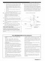
or cable system is grounded
so as to provide some
protection
against voltage surges and built-up static charges.
Article 810 of the National Electrical
Code, ANSI/NFPA
70,
provides
with regard
location of antenna discharge
electrodes,
and requirements
in perfor-
EXAMPLE
are required,
has used replacement
or have the same
information
to proper
grounding
of the
mast and supporting
structure, grounding
of the lead-in wire
to an antenna discharge
unit, size of grounding
conductors,
way, and
f)
Outdoor
Antenna Grounding
- ff an outside antenna or
cable system is connected
to the product, be sure the antenna
OF ANTENNA
unit, connection
for the grounding
to grounding
electrode.
GROUNDING
parts
as the original part. Unauthorized
may result in fire, electric shock, or other
Safety Check-
Upon
completion
of any service
or repairs
to
this product, ask the service technician
to perform safety
checks to determine
that the product ix in proper operating
condition.
22
Wall or Ceiling
Mounting
- The unit should
be mounted
ANTENNA
DISCHARGE
to a wall or ceiling
manufacturer.
only as recommended
by the
Heat - The product should be situated away from heat
sources such as radiators,
heat registers,
stoves, or other
SERVICE
Note
(including
to CATV
amplifiers)
system
that produce
installer:
ELECTRODE
(NEC
NEC
FCC INFORMATION
IMPORTANT
NOTICE:
DO NOT
MODIFY
THIS
Modifications
may void your
not expressly
authority,
granted
approved
by
to
use the product.
IMPORTANT:
accessories
shielded
be used.
follow
When
and/or
cables.
Follow
another
NOTE:
could
"B" digital
requirements
product
use only high
quality
void your FCC authorization
Utilize
to
provides
and found
Compliance
a reasonable
Part
15
with these
level of assurance
that
environment
will
other electronic
devices.
not installed
generates/uses
in the users manual,
operation
radio frequencies
and used according
of other electronic
to be the source
by turning
H)
either this product
by the interference.
power
of interference,
the unit "OFF"
the problem
outlets
or the device
or install
that
which
and "ON",
by using one of the
that are on different
or iklse) circuits
that is being
branch
(circuit
AC line filteffs.
[n the case of radio or TV interference,
relocate/reorient
the antenna. If the antenna lead-in is 300 ohm ribbon lead
the lead-in
to coaxial
type cable.
[f these corrective
measures do not produce satisfactory
results, please contact the local retailer authorized
to
distribute
this type of product.
appropriate
retailer,
Corp., U.S.A. 6660
90620.
The above
statements
found
distributed
subsidiaries.
by Yamaha
harmful
to the
If you can not locate
the
please contact Yamaha Electronics
Orangethorpe
Ave., Buena Park, CA
and, if
to the instructions
may cause interference
PART
to comply
listed in FCC Regulations,
devices.
your use of this product in a residential
not result in harmful
interference
with
This equipment
breaker
change
has been tested
is found
please try to eliminate
following
measures:
Relocate
affected
to
in the USA.
This product
with the requirements
for Class
this product
Cable/s supplied with this product MUST
all installation
instructions.
Failure to
instructions
use this product
connecting
SYSTEM
250.
with FCC regulations
does not guarantee
will not occur in all installations.
If this
can be determined
by the FCC,
ART
(for US customers)
product
This product, when installed as indicated
in the
instructions
contained
in this manual, meets FCC
Ymnaha
81_21)
NATIONAL ELECTRICAL CODE
Compliance
interference
UNIT!
requirements.
SECTION
heat.
This reminder
is provided to call the CATV system installer's
attention
to Article 820-40 of the NEC that provides
guidelines
for proper grounding
and, in particular,
specifies
that the cable ground shall be connected
to the grounding
system of the building, as close to the point of cable entry as
practical.
1
81_20)
/
(NEC
products
UNIT
SECTION
/
ELECTRIC
23
(NEC
/
apply
ONLY
Corporation
to those
products
of America
or its
devices.
Caution-ii
En
1
2
To assure
the finest performance,
carefully,
Keep
Install
please
it in a safe place
this sound
system
dust, moisture,
and/or
reference,
in a well ventilated,
place - away fi'orn direct
sunlight,
cold,
ventilation
30 crn on the top, 20 crn on the left and right,
the back of this unit,
3
Locate
this unit away
or transformers
4
(i.e. a room
condensation
inside
shock,
fire, damage
Avoid
installing
splashing.
motors,
20
may cause
object
this unit may be exposed
dripping
or
On the top of this unit, do not place:
-
Burning
objects
damage
to this unit, and/or
with liquid in them,
may cause
this unit.
electrical
shock
not to obstruct
inside
this unit rises,
and/or
personal
fire,
injury.
as they may fall and liquid
to the user and/or
Do not cover this unit with a newspaper,
etc. in order
and/or
as they may cause
Containers
damage
tablecloth,
heat radiation.
to
curtain,
If the temperature
it may cause fire, damage
possibly
9
this unit upside-down.
causing
until all connections
knobs
the power
and/or
cable
damage
this unit with chemical
the finish.
voltage
Use a clean,
specified
unit with a higher
than specified
to this unit, and/or
will not be held responsible
of this unit with
solvents;
this might
dry cloth.
on this unit must be used.
voltage
cause fire, damage
a voltage
Using
is dangerous
personal
for any damage
this
and may
injury.
Yamaha
resulting
during
a lightning
Yamaha
service
cabinet
"15 When
should
(i.e. vacation),
outlet.
"16 [nstall
or fix this unit. Contact
when
be opened
any service
disconnect
the AC power
Caution-iii
before
En
plug
and where
of time
from the wall
the AC power
easily.
"17 Be sure to read the "Troubleshooting"
errors
The
for any reasons.
this unit near the AC outlet
operating
qualified
is needed.
to use this unit for long periods
plug can be reached
from earphones
heat such
as
and headphones
can
loss.
WARNING
TO REDUCE THE RISK OF FIRE OR ELECTRIC
SHOCK, DO NOT EXPOSE THIS UNIT TO RAIN
OR MOISTURE.
This unit is not disconnected from the AC power
source as long as it is connected to the wall outlet, even
if this unit itself is turned off by @STANDRY/ON
This state is called the standby mode. In this state, this
unit is designed to consume a very small quantity of
power.
To prevent electric shock, match wide blade of plug to
wide slot and fully insert.
This Class B digital apparatus complies with Canadian
ICES-003.
POUR LES CONSOMMATEURS CANADIENS
Pour &iter les chocs dlectriques, introduire la lame la
plus large de la fiche dans la borne correspondante de
la prise et pousser jusqu'au fond.
Cet appareil num&ique de la classe B est conforme
la norme NMB-003 du Canada.
Please record
below.
the serial number
of this unit in the space
MODEL:
personnel
not planning
pressure
Hz.
IMPORTANT
other than specified.
storm.
to modify
never
sound
hearing
to excessive
plugging
from use
"1:3 To prevent damage by lightning,
keep the power cord and
outdoor antennas
disconnected
from a wall outlet or the unit
"14 Do not attempt
V AC, 50/60
are 110-120/220-240
The batteries
shall not be exposed
sunshine,
fire or like.
BEFORE
cords.
from the wall outlet,
the plug; do not pull the cord.
.1.1 Do not clean
"12 Only
on switches,
disconnecting
grasp
It may overheat,
damage.
Do not use force
.10 When
Voltages
only)
of this unit
FOR CANADIAN CUSTOMERS
Do not plug in this unit to a wall outlet
Do not operate
models
plug
to this unit,
injury.
are complete.
8
and General
on the rear panel
voltage
cause
injury.
to liquid
personal
(Asia
SELECTOR
to set this
the AC power
must be set for your local main
into the AC wall outlet.
2"1 Excessive
may fall onto
Other components,
as they may cause damage
discoloration
on the surface of this unit.
(i.e. candles),
and disconnect
an electrical
personal
foreign
from
with
to prevent
-
-
7
which
to this unit, and/or
this unit where
this unit and/or
6
appliances,
sounds.
SELECTOR
The VOLTAGE
and 20 crn on
with a humidifier)
this unit,
"19 VOLTAGE
of at least
Do not expose this unit to sudden temperature
changes
cold to hot, and do not locate this unit in a environment
high humidity
5
fi'om other electrical
to avoid humming
vibration,
space
this unit, press @STANDBY/ON
moving
unit in the standby mode,
from the wall outlet.
cool, dry, clean
heat sources,
Allow
"18 Before
read this rnanual
for future
concluding
section
on common
that this unit is faulty.
Serial No.:
The serial number
Retain this Owner's
reference.
is located
Manual
on the rear of the unit.
in a safe place for future
Features
...................................................................
Getting
started
Quick
start
2
........................................................
guide
....................................................
4
Preparation:
Check the items .....................................
Step 1: Set up your speakers ......................................
Step 2: Connect
your DVD player and other
components
............................................................
4
5
6
7
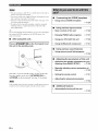
What
8
to do with this unit?
.....................
.................................................................
44
45
48
3 OPTION
50
MENU
control
.............................................................
9
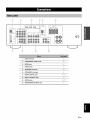
Rear panel ..................................................................
Placing speakers .......................................................
9
10
Connecting
speakers ................................................
Setting the speaker impedance
11
(U.S.A.
[nformation
Information
12
13
14
and Canada
models only) .......................
on jacks and cable plugs ......................
on HDM[ TM ..........................................
Connecting
video components
.................................
Connecting
Connecting
audio components
.................................
a Yamaha
iPod TM universal
dock and
17
Bluetooth
Connecting
adapter .............................................
to the VIDEO AUX jacks on the
18
TM
15
Advanced
setup
18
19
Connecting
the power cable .....................................
Turning on and off the power ..................................
19
19
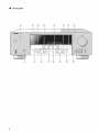
Front panel
Basic
setup
Selecting
display
..................................................
the SCENE
Using
control
...........................
on the SCENE
feature
...........
................................................................
field
Sound
FM/AM
programs
...........................................
field program descriptions
............................
tuning
......................................................
Automatic
tuning
.....................................................
28
29
30
34
34
37
37
Manual preset tuning ...............................................
Selecting preset stations ...........................................
38
39
Exchanging
preset stations ......................................
Using iPod TM ..........................................................
Controls and functions
for iPod TM ...........................
39
41)
40
Using
41
components
...........................
Pairing the Bluetooth TM adapter and
your Bluetooth TM component
..............................
Playback
of the Bluetooth
component
41
.................
41
Recording ..............................................................
42
TM
• _
II
55
61)
62
63
(at the end of this manual)
Front panel ................................................................
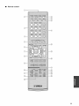
Remote
control
.......................................................
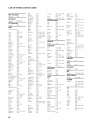
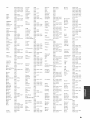
control
codes
.................................
i
ii
iii
24
27
37
38
TM
L_'=
24
Manual tuning ..........................................................
Automatic
preset tuning ...........................................
Bluetooth
Og,
About this manual
29
Basic operations
.......................................................
Additional
operations ...............................................
Sound
_
54
22
the desired SCENE template ....................
your original SCENE templates
................
remote
Playback
templates
......................................................
51
.... 5 1
53
20
.............................................................
Selecting
Creating
........................................
Troubleshooting
.....................................................
Glossary ..................................................................
Specifications
.........................................................
Index .......................................................................
List of remote
front panel ............................................................
Connecting
the FM and AM antennas
.....................
...................................................
features
Controlling
this unit, a TV, or other components
Setting remote control codes ...................................
_L'=
Connections
43
Using set menu ........................................................
1 SOUND MENU ....................................................
2 INPUT MENU ......................................................
Remote
Step 3: Turn on the power and
press SCENE 1 button ...........................................
do you want
Set menu
3
• -"4":'indicates a tip for your operation.
• Some operations can be performed by using either the
buttons on the front panel or the ones on the remote
control. [n case the button names differ between the front
panel and the remote control, the button name on the
remote control is given in parentheses.
• This manual is printed prior to production. Design and
specifications are subject to change in part as a result of
improvements, etc. [n case of differences between the
manual and product, the product has priority.
• "@STANDBY/ON"
or "@ DVD" (example) indicates
the name of the parts on the front panel or the remote
control. Refer to the attached sheet or the pages at the end
of this manual for the information about each position of
the parts.
• The symbol "_ " with page number(s) indicates the
corresponding reference page(s).
R En
Built-in 5-channel power amplifier
Sophisticated
•
•
40-station
random
models]
•
Automatic
preset
8 f_)
HDMI (High-Definition
Mininlunl
[U.S.A.
RMS
output
and Canada
(1 kHz, 0.9% THD,
Front: 100 W/ch
Center:
power
•
100 W
Surround:
[Other
video
100 W/ch
•
6 f_)
Preset
•
SCENE
100 W/ch
SCENE
templates
template
for various
customizing
situations
capability
Proprietary
Yamaha technology
multi-channel
surround sound
•
Compressed
Music
•
Dolby
•
•
Dolby Pro Logic/Dolby
DTS decoder
•
Virtual
•
SILENT
Digital
preset
Multimedia
for standard,
(includes
tuning
1080p
enhanced
video
signal
Interface)
or high-definition
transmission)
terminal
to connect
as YDS-10,
a Yamaha
sold separately)
iPod universal
or Bluetooth
dock
adapter
(such
sold separately).
Other features
Enhancer
•
192-kHz/24-bit
•
6 additional
input jacks for discrete
D/A converter
•
Component
video
input/output
(3 COMPONENT
Decoders and DSP circuits
•
interface
as YBA-10,
SCENE select function
•
DOCK
(such
100 W
Surround:
and direct
tuning
DOCK terminal
models]
(1 kHz, 0.9% THD,
Front: 100 W/ch
Center:
HDMI
FM/AM tuner
for the creation
of
)node
VIDEO
•
iPod controlling
•
Sleep
•
Cinema
and music
•
Remote
control
multi-channel
input
capability
INs and 1 MONITOR
OUT)
capability
timer
night listening
with preset
)nodes
remote
control
codes
decoder
CINEMA
Pro Logic
II decoder
DSP
CINEMA
_"
D[I
iPod
DiGiTAL
"iPod" is a trademark of Apple Inc., registered in the U.S. and
other countries.
Manufactured
under
license
"Dolby",
"Pro Logic",
of Dolby
Laboratories.
from Dolby
TM
Laboratories.
and the double-D
symbol
are trademarks
BluetoothTM
Bluetooth
used
is a registered
by Ymnaha
trademark
in accordance
of the Bluetooth
with a license
SIG and is
agreement.
SILENT T_
CINEMA
"SILENT CINEMA" is a trademark of YmnahaCorporation.
Digital Surroun8
"DTS"
DTS,
"HDMI",
the "HDMI"
Interface"
are trademarks
logo and "High-Definition
Licensing
LLC.
or registered
Yamaha
and the Electronic
Electronics
equipment
come
sensitive
without
importantly,
are registered
trademarks
of
of HDM[
Consumer
Since hearing damage from loud sounds is often
undetectable
until it is too late. Ymnaha and the
_,_i_,_-,_
out of your
that lets the sound
Electronic
_L._
annoying
without
Surround"
For A Lifetime
Association's
it at a safe level. One
loud and clear
and, most
hearing.
Industries
want you to get the most
by playing
through
distortion
2 En
Group
Digital
Multimedia
trademarks
We Want You Listening
and "DTS
Inc.
blaring
affecting
or
your
Industries
Electronics
Group
prolonged
exposure
Association's
recommend
you
from excessive
Consumer
,x
r
_a,_,:i}
to avoid
volume
levels.
LISTENING
•
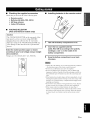
Checking the supplied accessories
Check
that you
received
all of the following
Installing batteries in the remote control
parts.
'3
Remote control
Batteries (2) (AAA, R03, UM-4)
AM loop antenna
Indoor FM antenna
•
VOLTAGE SELECTOR
(Asia and General models only)
Caution
The VOLTAGE
SELECTOR
on the rear panel of this
unit must be set for your local voltage
plugging
the power
Improper
setting
cause damage
hazard.
BEFORE
cable into the AC wall outlet.
of the VOLTAGE
to this unit and create
SELECTOR
a potential
may
1
Take off the battery compartment
2
Insert thetwo supplied batteries
(AAA, R03, UM-4) according to the polarity
markings (+ and -) on the inside of the
battery compartment.
3
Snap the battery compartment
into place.
Select the switch position (upper or lower)
according to your local voltage using a straight
slot screwdriver.
Voltages are l 10-120/220-240 V AC, 50/60 Hz.
--
VOLTAGE
SELECTOR
--
cover.
fire
• Change
all of the batteries
- the operation
range
if you notice
of the remote
• Do not use all old battery
• Do not use different
manganese
these different
color.
• If the batteries
of batteries
together.
types of batteries
have leaked,
material
clothing,
etc. Clean
the battery
as alkaline
and
careikllly
of them
or letting
immediately.
it come
compartment
as
and
Avoid
into contact
thoroughly
with
before
new batteries.
• Do not throw
away
batteries
with general
of them correctly in accordance
• If the remote control is without
or if exhausted
the contents
is cleared,
code.
(such
may have the same shape
dispose
the leaked
minutes,
condition:
decreases.
Read the packaging
touching
installing
the following
control
and a new one together.
types
batteries)
cover back
batteries
of the memory
insert new batteries
house
waste;
dispose
with your local regulations.
batteries for more than 2
remain
in the remote
may be cleared.
When
and set up the remote
control,
the memory
control
3
En
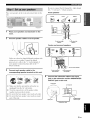
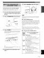
The following
DVD movie
steps describe
playback
Video monitor
the easiest
way to enjoy
i i
;;i;
i
i
?
in your home theater.
Front right
speaker
Prepare
q
the following
items.
Subwoofer
Front left
speaker
Surround right
speaker
Speakers
Front speaker ..................................... x 2
Center speaker ................................... x 1
Surround speaker .............................. x 2
Select magnetically shielded speakers. The
minimum required speakers are two front speakers.
Active subwoofer
Center speaker
=
I
DVD player
...................................
x 1
Select an active subwoofer equipped with an RCA
input jack.
Surrou/nd left
speaker
Speaker cable .........................................
Subwoofer cable .....................................
x5
x 1
Select a monaural RCA cable.
DVD player ..............................................
x 1
Select DVD player equipped with coaxial digital
audio output jack and composite video output
jack.
Video monitor
.........................................
x 1
Select a TV monitor, video monitor or projector
equipped with a composite video input jack.
Video cable .............................................
x2
Select an RCA composite video cable.
Digital coaxial audio cable .................... x 1
Enjoy DVD playback!
4
En
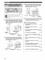
Be sure to connect
the left channel
(R), "+" (red) and "-" (black)
Place your speakers
unit.
in the room
and connect
(L), right channel
properly.
Front speakers
them to this
Loosen
V
Place your speakers and subwoofer in the
room.
@
@
2
\
Connect speaker cables to each speaker.
To the front left
speaker
To the front right
speaker
Center
and surround
speakers
_
Insert
Cables
are colored
a stripe, groove
(grooved,
perhaps
Connect
with
the striped
etc.) cable to the "+" (red) terminals
your speaker.
(black)
or shaped differently,
or ridge. Connect
of
the plain cable to the "-"
terminals.
To the center speaker
Connect each speaker cable to the
corresponding speaker terminal on this unit.
To the surround
right speaker
4
To the surround
left speaker
Connect the subwoofer cable to the input
jack on the subwoofer and the SUBWOOFER
OUTPUT jack on this unit.
Subwoot'er
@
Make
sure that this unit and the subwoofer
unplugged
@
_
AV receiver
from the AC wall outlets.
Twist the exposed
together
- - _
are
to prevent
wires of the speaker
cables
short circuits.
@
Do not let the bare speaker
wires touch each other.
@
Do not let the bare speaker
wires touch any metal
part of this unit.
Input jack
_
SUBWOTOjFaER
Subwoofer
cable
5 En
Connect the video cable to the video input
jack on your video monitor and the VIDEO
MONITOR OUT jack on this unit.
Video
Make sure that this unit and the DVD
player are unplugged from the AC wall
outlets.
Video cable
AV receiver
VIDEO MONITOR
OUT jack
Connect the power plug of this unit and other
components into the AC wall outlet.
•
•
DVD player
AV receiver
Video input jack
4
Connect the digital coaxial audio cable to the
digital coaxial audio output jack on your DVD
player and the DVD DIGITAL INPUT COAXIAL
jack on this unit.
monitor
For further
connections
Using the other kind of speaker
combinations
_' P. 10
Connecting a video monitor and
DVD player
_' P. 15
Connecting a cable TV/satellite tuner and
DVD recorder
_' P. 15
_
_s
S
Digital coaxial
audio output
jack
Connecting to the HDMI jacks
Digital coaxial
cable
2
audio
DVD DIGITAL INPUT
COAXIAL jack
Connect the video cable to the composite
video output jack on your DVD player and the
DVD VIDEO jack on this unit.
DVD player
AV receiver
_' P. 16
Connecting to the COMPONENT VIDEO
jacks
_' P. 16
Using the VIDEO AUX jacks on the front
panel
_' P. 18
Connecting a CD player and an MD
recorder
_' P. 17
S
___=.____.___
S
v,o_o
_
Connecting a DVD player via analog
multi-channel audio connection
_' P. 17
Connecting an outdoor FM/AM antenna
_' P. 19
Composite
video
output jack
SEn
__
Video cable
DVD VIDEO jack
Connecting an iPod/Bluetooth
dock
_' P. 18
'_/R,IR_f.,,m-
5
Rotate @VOLUME
to adjust the volume.
Check the type of the connected speakers.
If the speakers are 6 ohm speakers, set "SP IMP." to
"6f_MIN" before using this unit (see page 12).
1
Turn on the video monitor and then set the
input source selector of the video monitor to
this unit.
2
Press @STANDBY/ON
on the front panel.
When you change the input source o1"sound field program, the
SCENE mode is deactivated and the indicator on the SCENE
button turns off.
•
About SCENE function
Just
by pressing
unit
and
one
recall
program
according
assigned
to the
built
SCENE
your
input
you
button.
of input
can turn
source
to the SCENE
SCENE
combinations
button,
favorite
and
template
The
that
SCENE
sources
and
on
sound
has
this
field
been
templates
sound
are
field
programs.
-_,._
If you
connect
SCENE
control
component
the DVD
Press @SCENE 1.
"DVD Viewing" appears in the front panel display,
and this unit automatically optimize own status for
the DVD playback.
•
a Yamaha
signals,
product
and start playback.
player
that has capability
this unit can automatically
for further
Refer
to the instruction
Default
SCENE
button
1
DVD Viewing
- input
source:
DVD
- sound
field
program:
STRAIGHT
you want to listen to a music
the connected
DVD player
music for this room.
SCENE
2
Disc
source:
DVD
- sound
field
program:
5ch Stereo
you want to listen to a music
the connected
DVD player
music for this room.
up while
SCENE
3
TV Viewing
SCENE
4
disc from
as the background
_1
- input
source:
- sound
field
For when
Start playback of the desired DVD on your
player.
disc from
as the background
Listening
- input
For when
lights
of
information.
The name of the SCENE
template
and its description
For when
button
the
manual
Using the other SCENE buttons
SCENE
The indicator on the selected SCENE
this unit is ill the SCENE mode.
of the
activate
DTV/CBL
program:
STRAIGHT
you want to watch a TV program.
Radio Listening *2, _3,*4
- input source: TUNER
- sound field program: Music Enh. 5ch
For when you want to listen to a music program
from the FM radio station
7
En
_1 You must connect
advance.
a cable
See page
_2 You need to connect
unit ill advance.
TV or a satellite
the supplied
See page
_4 To achieve
the assigned
FM and AM antennas
to this
radio
station.
See pages
orient
the connected
37 to
•
•
Customizing
the SCENE
templates
Using various SCENE templates
_ P. 24
information.
the best possible
AM loop antenna, or adjust
indoor FM antenna.
ff you cannot
to this unit ill
19 for details.
_3 You have to tune into the desired
39 for the tuning
tuner
16 for details.
find the desired
SCENE
reception,
the position
•
situation,
template
of the end of the
you can select
for the SCENE
page
24 for details.
•
After using this unit...
buttons.
Using various
input
sources
•
Basic controls of this unit
_ P. 29
•
Enjoying FM/AM radio programs
_ P. 37
•
Using your iPod with this unit
_ P. 40
•
Using the Bluetooth component
_ P. 41
and change
See
Press @STANDBY/ON
on the front panel to set
this unit to the standby mode.
•
•
Using various
sound
features
Using various sound field programs
_ P. 34
•
•
Adjusting
the parameters
of this unit
Optimizing the speaker parameters for your
listening room (BASIC SETUP)
_ P. 22
Manually adjusting various parameters of
this unit
_ P. 43
This unit is set to the standby mode. To turn on this unit
from the standby mode, press @STANDBY/ON
(or
@POWER) on the front panel. See page 19 for details.
Setting the remote control
_ P. 51
Adjusting the advanced parameters
_ P. 54
In the standby
in order
mode,
to receive
this unit consumes
infrared
signals
from
a small amount
the remote
of power
control.
•
Additional
•
Automatically
features
turning off this unit
_ P. 33
SEn
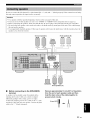
m
VIDEO
@@@@
ow
OW/CSL EN_W O AUOkOCD
@
DOCK
terminal
18
@
COMPONENT
@
HDMIjacks
16
@
VIDEO
15
@
ANTENNA
@
SPEAKERS
@
DIGITAL
@
MULTI CH INPUT
@
AUDIO
VIDEO
jacks
jacks
terminals
19
terminals
INPUT
II
jacks
15, 17
jacks
17
jacks
SUBWOOFER
16
15, 17
OUTPUT
jack
!!
9
En
|¶'lllll_"lff'lll-
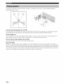
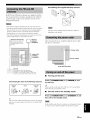
The speaker layout below shows the speaker setting we recommend. You can use it to enjoy CINEMA DSP and
multi-channel audio sources.
30 _
SR
,"SL '
-
, 6o_'_
Front left and right speakers (FL and FR)
The front speakers are used for the main source sound plus effect sounds. Place these speakers at an equal distance from the
ideal listening position. The distance of each speaker from each side of the video monitor should be the same.
Center speaker (C)
The center speaker is for the center channel sounds (dialog, vocals, etc.). If for some reason it is not practical to use a
center speaker, you can do without it. Best results, however, are obtained with the full system.
Surround left and right speakers (SL and SR)
The surround speakers are used for effect and surround sounds.
Subwoofer (SW)
The use of a subwoofer with a built-in amplifier, such as the Yamaha Active Servo Processing Subwoofer System, is
effective not only for reinforcing bass frequencies from any or all channels, but also for high fidelity sound reproduction
of the LFE (low-frequency effect) channel included in Dolby Digital and DTS sources. The position of the subwoofer is
not so critical, because low bass sounds are not highly directional. But it is better to place the subwoofer near the front
speakers. Turn it slightly toward the center of the room to reduce wall reflections.
10
En
I'IIIII:I"I(I'IIF
Be sure to connect the left channel (L), right channel (R), '%" (red) and "-" (black) properly. If the connections are faulty,
this unit cannot reproduce the input sources accurately.
Caution
•
•
•
•
Use speakers with the specified impedance shown on the rear panel of this unit.
If you are to use 6 ohm speakers, be sure to set "SP IMP." to "6f_MIN" before using this unit (see page 12).
Before connecting the speakers, make sure that this the AC power plug is disconnected from the AC wall outlet.
Do not let the bare speaker wires touch each other or let them touch any metal part of this unit. This could damage
this unit and/or speakers.
• Use magnetically shielded speakers. If this type of speakers still creates the interference with the monitor, place the
speakers away from the monitor.
Surround speakers
Right
Left
Front speakers (B)
Right
Left
Subwoofer
Right
Left
Front speakers (A)
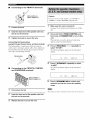
•
Before connecting
terminal
to the SPEAKERS
A speaker cord is actually a pair of insulated cables
running side by side. Cables are colored or shaped
differently, perhaps with a stripe, groove or ridges.
Connect the striped (grooved, etc.) cable to the "+" (red)
terminals of this unit and your speaker. Connect the plain
cable to the "-" (black) terminals.
Remove approximately 10 mm (3/8") of insulation
from the end of each speaker cable and then
twist the bare wires of the cable together to
prevent short circuits.
10 mm (3/8")I
!
|¶'lllll_"l(|'lll•
Connecting to the FRONT A terminals
2/
_"
Red: positive(+)
Black:
negative
Caution
(-)
If you are to use 6 ohm speakers, set "SP IMP." to
"6f_MIN" as follows BEFORE using this unit.
3
1
1
Loosen the knob.
2
Insert the bare end of the speaker wire into
the slit on the terminal.
3
See page 19 for details about turning on or off this
unit.
2
Press and hold @TONE
CONTROL
then press @STANDBY/ON
unit.
Tighten the knob to secure the wire.
and
to turn on this
This unit turns on, an the advanced setup menu
appears in the front panel display.
Connecting the banana plug
(except Europe, Russia, Korea, and Asia models)
The banana plug is a single-pole electrical connector
widely used to terminate speaker cables. First, tighten the
knob and then insert the banana plug connector into the
end of the corresponding terminal.
Banana
Make sure this unit is turned off.
Press @PROGRAM
select "SP IMP.".
<1 It>
repeatedly to
The following display appears in the front panel
display.
plug
SP
4
]] ;"gP° -
Press @STRAIGHT
"6_MIN".
_i?!;;!H ]] N
repeatedly to select
The following display appears in the front panel
display.
Connecting to the FRONT B, CENTER,
and SURROUND terminals
SP ]:MP°-
6_H]:N
Red: positive (+)
Black: negative (-)
5
Press @STANDBY/ON
to confirm your
selection and set this unit to the standby
mode.
1
Press down thetab.
The setting
2
Insert the bare end of the speaker wire into
the hole on the terminal.
3
Release the tab to secure the wire.
12
En
you made
is reflected
next time
you turn on this unit.
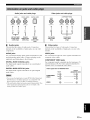
'l,lllll:i,'l(l,lli _
Audio jacks and cable plugs
AUDIO
(_
DIGITAL AUDIO
(_
COAXIAL
(Red)
@ @@@
@
(Yellow)
t
Left and right
analog audio
cable plugs
•
VIDEO
(Orange)
t t
unit
has
depends
three
Coaxial
digital audio
cable plug
on the
types
of audio
availability
(Green)
t
Optical
digital
audio cable
plug
jacks.
of audio
jacks
(Blue)
t
plug
Connection
on your
other
•
Video jacks
This
unit
has
two
t t
types
of video
AUDIO jacks
VIDEO jacks
For conventional analog audio signals transmitted via left
and right analog audio cables. Connect red plugs to the
right jacks and white plugs to the left jacks.
For conventional composite video signals transmitted via
composite video cables.
DTS bitstreams.
digital
signals
All digital
analog
signals
AUDIO
to input PCM,
input jacks
digital
and analog
input at the digital
OUT (REC)
signals
jacks
Dolby
Digital
are compatible
with up to 96 kHz of sampling
• This unit handles
audio
jacks
Video signal
and
frequency.
are not output
flow
for MONITOR
Input
with
independently.
Thus
jacks
on your
video
COMPONENT VIDEO jacks
For component signals, separated into the luminance (Y)
and chrominance (PB, Pr) video signals transmitted on
separate wires of component video cables.
COMPONENT
VIDEO
• You call use the digital
of input
Connection
components.
DIGITAL AUDIO OPTICAL jacks
For digital audio signals transmitted via optical digital
audio cables.
availability
jacks.
depends
monitor.
DIGITAL AUDIO COAXIAL jacks
For digital audio signals transmitted via coaxial digital
audio cables.
on the
(Red)
Component
video cable
plugs
Composite
video cable
Audio jacks
This
COMPONENT VIDEO
Y
PB
PR
DIGITALAUDIO
OPTICAL
@@@
(White)
Video jacks and cable plugs
V,DEO
OUT
Output
(MONITOR OUT)
p.®
PB®
p.®
-
PB ®
¥®
Y®
®
®
at the
jacks.
I
13
En
|¶qllll_"l(|qll-
Audio signals
monitor.
input at the HDMI jack are not output
To enjoy the sound
-make
-mute
from speakers
connected
by connecting
signals
connected
only when this unit is turned
instruction
available
manual
output
your video monitor
At that time, audio/video
video monitor
audio/video
from the connected
signals
of each connected
depend
HDMI cable
plug
• We recommend using all HDM[ cable shorter than 5 meters
(16 feet) with the HDM[ logo printed on it.
14
En
connection
(see page
from the connected
video
DVI-D jack) to connect
16).
and video source component
component
on the specification
component.
HDMI
• Use a conversion cable (HDM[ jack _
this unit to other DVI components.
but output
to this unit using HDMI
(such as DVD player etc.) are output
on and set to the input source
HDMI jack and cable plug
I
terminals
to this unit,
an analog or digital connection
besides the HDMI
the volume of the connected
video monitor.
You can play back pictures
connections.
Furthermore,
from any speaker
to the
(DVD or DTV/CBL).
of the connected
video monitor.
Refer to the
'lqllll:i,'l(l,lli _
You call also connect a video monitor, DVD player, digital
and cable TV to this unit using the HDM[ o1"COMPONENT
VIDEO
•
connection
(see page
TV,
Make sure that this unit and other
components are unplugged from the
AC wall outlets.
16).
Connecting a video monitor and a DVD
player
Connecting a cable TV/satellite tuner
and a DVD recorder
@@@
fN
<
©
Audio
©
When
connect
digital
>
ot
Video
DVD player
........
_< >
.w
indicates
recommended
indicates
alternative
you use the internal
the digital
or analog
or analog
audio
Cable TV or
Satellite tuner
monitor*
connections
connections
........
DVD recorder
indicates
recommended
indicates
alternative
connections
connections
tuner of the TV as the input source,
audio
input jacks
output jacks
of the TV and
of this unit.
15
En
[_iqllll'i"l(l'lll"
•
Connecting to the HDMI or COMPONENT VIDEO jacks
You can enjoy high-quality
pictures by connecting
HDMI or COMPONENT
VIDEO connections.
Be sure to connect
your
video components
your video monitor
ill the same way
you connect
your video monitor to this unit using an HDMI or COMPONENT
the HDMI or COMPONENT
VIDEO connection.
HDMI connection
Audio
signals
input at the HDMI
- make an analog
video
connection,
monitor
from speakers
or digital
monitor
from the
connected
connection
to this unit using
to this unit. For example,
connect
your
jack are not output
but output
HDMI connection
(see page 15).
- mute the volume of the connected
Video
your
video components
Connecting to the COMPONENT
from any speaker terminals
connected video monitor.
To enjoy the sound
VIDEO
and video source components
Video
if you connect
to this unit using
VIDEO jacks
monitor
DVD player
to this unit,
besides
the
video monitor.
-T
©
Cable TV or
satellite tuner
T
©
©
©
©
DVD player
Cable TV or
satellite tuner
• Connect the input source components to the HDM[ DVD or
HDM[ DTV/CBL jack to display the video images on the video
monitor connected to the HDM[ OUT jack.
• Audio/video signals output from the connected component
(such as DVD player etc.) are output to the connected video
monitor only when this unit is turned on and set to the input
source (DVD or DTV/CBL).
• Available audio/video signals depend on the specification of the
connected video monitor. Refer to the instruction manual of
each connected component.
16
En
DVDrecorder
'lqflfl:i,'l(l,lli _
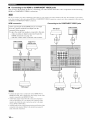
•
Connecting a CD player and a CD
recorder/MD recorder
Make sure that this unit and other
components are unplugged from the
AC wall outlets.
When
you connect
connection,
priority
INPUT jack.
your
CD player
via analog
is given to the signal
and digital
input at the DIGITAL
out
Audio
y
Audio in
CD recorder or MD
recorder
CD player
........
out y
indicates
recommended
indicates
alternative
connections
connections
•
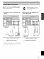
Connecting
to the MULTI CH INPUT jacks
This unit is equipped with 6 additional input jacks (FRONT LIR, SURROUND LIR, CENTER and SUBWOOFER) for
discrete multi-channel input from a multi-format player, external decoder or sound processor. Connect the output jacks
on your multi-format player or external decoder to the MULTI CH INPUT jacks. Be sure to match the left and right
output jacks to the left and right input jacks for the front and surround channels.
• When you select the component connected to the MULTI CH
INPUT jacks as the input source (see page 30), this unit
automatically turns off the digital sound field processor, and
you cannot select sound field programs.
• This unit does not redirect signals input at the MULTI CH
INPUT jacks to accommodate for missing speakers. We
recommend that you connect a 5.l-channel speaker system
before using this feature.
Multi-format player or
external decoder
17
En
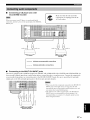
|_i'll If I:i"I (I'll I"
Use the VIDEO AUX jacks on the front panel to connect a
game console or a video camera to this unit.
-5
components are unplugged from the
AC wall outlets.
Make sure that this unit and other
I
J
|
This unit is equipped with the DOCK terminal on the rear
panel that allows you to connect a Yamaha iPod universal
dock (such as YDS-10, sold separately) or Bluetooth
adapter (such as YBA-10, sold separately). Connect a
Yamaha iPod universal dock or Bluetooth adapter to the
DOCK terminal on the rear panel of this unit using its
dedicated cable.
Caution
Be sure to turn down the volume of this unit and other
components before making connections.
• The audio signals input at the DOCK terminal on the rear panel
take priority over the ones input at the VIDEO AUX jacks.
• To reproduce the source signals input at these jacks, select
"V-AUX" as the input source.
• The audio signals input at the PORTABLE mini jack take
priority over the ones input at the AUDIO L/R jacks.
Refer to "Using iPodTM''on page 40 for playback of your iPod
and "Using Bluetooth components" on page 41 for playback of
your Bluetooth components.
TM
I
3.5 mm
stereo mini
plug
YamahaiPoduniversaldock or
Bluetoothadapter
18
En
Game console or
video camera
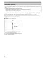
lqllll:i"lffqli
_
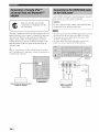
Assembling the supplied AM loop antenna
Both FM and AM indoor antennas are supplied with this
unit. In general, these antennas should provide sufficient
signal strength. Connect each antenna correctly to the
designated terminals.
/
• The AM loop antenna should be placed away from this unit.
• A properly installed outdoor antenna provides clearer reception
than all indoor one. If you experience poor reception quality,
install all outdoor antenna. Consult the nearest authorized
Yamaha dealer or service center about outdoor antennas.
The types
depending
of the supplied
AM loop antenna
is different
on the models.
• The AM loop antenna should always be connected, even if an
outdoor AM antenna is connected to this unit.
Outdoor
AM antenna
_
AM loop
Once all connections are complete, plug the power cable
into the AC wall outlet.
(supplied)
ft) ol vilul-covered
wire
extended outdoors h'om a
\Villd(}w.
Use a 5 to l0 m (16 to 32
[_
antenna
Power cable
antenna
(supplied)
(U.S.A.
I
ndoor
model)
FM
To the AC wall outlet
Ground
For maxinmm safety and minimum
interllzrence, connect the antenna GND
terminal to a good earth ground. A good earth
ground is a metal stake driven into moist earth.
•
Connecting the wire of the AM loop antenna
Open the
lever
Insert
Close the
lever
Turning on this unit
Press @STANDBY/ON
on this unit.
(or @ POWER)
to turn
?_t_
When
before
•
you turn on this unit, there
this unit can reproduce
will be a 4 to 5-second
Set this unit to the standby mode
Press @STANDBY/ON
(or @ STANDBY)
this unit to the standby mode.
The wire of the AM loop antenna
and you can connect
terminal.
either
does
delay
sound.
to set
not have any polarity
end of the wire to AM or GND
In the standby mode, this unit consumes a small amount of power
in order to receive infrared signals from the remote control.
19
En
|¶']llll_"l(|qll-
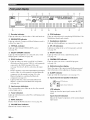
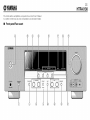
@ Decoder indicator
Lights up when any of the decoders of this unit functions.
(2) ENHANCER
@
PCM
Lights
Modulation)
indicator
@
@ VIRTUAL indicator
Lights up when Virtual CINEMA DSP is active
(see page 36).
@
@ SILENT CINEMA indicator
@
Lights up when headphones are connected and a sound
field program is selected (see page 36).
Lights
DOCK
Lights
Flashes
component
Bluetooth
is in the paring
adaptor
component
adaptor
and the Bluetooth
(see page
is searching
18) or the
is connected
are connected
(see page 30).
to the set of front speakers
selected
NIGHT
indicator
up when you select a night listening
mode
CINEMA
Lights
DSP indicator
up when you select a sound field program
(see page 34).
@
Multi-information
other
@
information
SLEEP
Lights
display
the name of the current
sound
when adjusting
field program
or changing
and
settings.
indicator
up while the sleep timer
is on (see page 33).
the Bluetooth
@
(see page 41 ).
Light up while the connected
adaptor
as the input
Yamaha Bluetooth
sold separately)
indicator
up when headphones
SP A B indicators
Shows
while the connected
(such as YBA-10,
•
is selected
(Pulse Code
(see page 31 ).
@
your iPod in a Yamaha
(see page 18) when V-AUX
source.
PCM
audio signals.
(see page 29).
iPod universal dock (such as YDS-10, sold separately)
connected
to the DOCK terminal of this unit
•
Lights
Light up according
indicator
up when you station
digital
Headphones
Lights up when the Compressed Music Enhancer mode is
selected (see page 34).
•
indicator
up when this unit is reproducing
Yamaha
to the Bluetooth
Input channel
and speaker
indicators
Bluetooth
component
_=_
LFE indicator
(see page 18).
@
Input source
The corresponding
selected
Input channel indicators
indicators
cursor
lights up to show the currently
LFE indicator
input source.
Lights
@ Tuner indicators
Lights up when this unit is in the FM or AM tuning mode
(see page 37).
Input channel
Indicate
@ MUTE indicator
Flashes while the MUTE function is on (see page 30).
@ VOLUME level indicator
Indicates the current volume level.
20
En
up when the input signal contains
the LFE
signal.
indicators
the channel
input signal.
components
of the current
digital
PI';IIII_"I(|'IIF
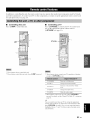
•
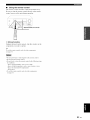
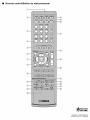
Using the remote control
The remote control transmits a directional infrared ray.
Be sure to aim the remote control directly at the remote
control sensor on this unit during operation.
Q Infrared
Outputs
window
infrared
component
control
signals.
Aim this window
at the
you want to operate.
-4'-To set the remote control codes for other components,
see page 53.
• Do not spill water or other liquids on the remote control.
• Do not drop the remote control.
• Do not leave or store the remote control in the following types
of conditions:
- places of high humidity, such as near a bath
- places of high temperature, such as near a heater or stove
- places of extremely low temperatures
- dusty places
• To set the remote control codes for other components,
see page 53.
21
En
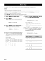
The "BASIC SETUP" feature is a useful way to set up your system quickly and with minimal effort.
• Make sure you disconnect your headphones from this unit.
• If you wish to configure this unit manually using more precise adjustments, use the detailed parameters ill "SOUND MENU"
(see page 45).
• Altering ally parameters ill "BASIC SETUP" resets all parameters manually adjusted ill "SOUND MENU" (see page 45).
• Initial settings are indicated ill bold under each parameter.
• Press @ RETURN on the remote control to return to the previous menu level.
1
Press @AMP
on the remote control.
5
Press @V to select"SUBWOOFER"
@<1/I:>
2
Press @MENU.
"BASIC SETUP" appears in the front panel display.
:: i=:i'i2:: .i.L.. .Di=.
3
and then
to select the desired setting.
Press @ENTER
LJr"
to enter "BASIC SETUP".
:iii:L!iiii:i.,.!0(?F::EF:i:
.... '.?E:iii:
Choices: YES, NONE
• Select "YES" if you have a subwoofer in your
system.
• Select "NONE" if you do not have a subwoofer in
your system.
"ROOM" appears in the front panel display.
Press @V to select "SPEAKERS"
"""'""""
i'::.E...ii...ii" i :=
4
:iii;i:ii
:' ":"
i
Press @<I / t> to select the desired setting.
Select the size of the room where you have installed
your speakers. In general, the room sizes are defined
as follows:
and then
@<I / I:> to select the number of speakers
connected to this unit.
,="i=:i=""","i.."i="i=::="....
....: _
L.. F"; _".. L.. _"......: ....
i::::.... ,....i..
,...: .=. F" r..
Choices: S, M, L
[U.S.A. and Canada models]
S (small)
16x 13 ft, 200 ft2 (4.8 x 4.0 m, 20 m2)
M (medium) 20 x 16 ft, 300 ft 2 (6.3 x 5.0 m, 30 m2)
L (large)
26 x 19 ft, 450 ft 2 (7.9 x 5.8 m, 45 m2)
[Other models]
S (small)
3.6 x 2.8 m, 10 m2
M (medium) 4.8 x 4.0 m, 20 m2
L (large)
6.3 x 5.0 m, 30 m2
22
En
2spk
_
3 spk
_
4spk
c_
sL
5spk
_cR?
,ff
gR,
_
_
Front L/R
:_'
Front L/R, Center
iSR?
Front L/R, Surround
L/R
Front L/R, Center, Surround L/R
Press _7 to select "SET" and then _<_/I:>
to select the desired setting.
10
11
_%,._
You call also press @MENU to cancel the setup procedure.
Press _ ENTER to confirm your selection.
If you selected "SET" in step 7, each speaker outputs
a test tone twice in turn. "CHECK:TestTone" appears
in the front panel display for a few seconds and then
"CHECK OK?" appears in the front panel display.
r" r::. •...................
• Select "FR" to adjust the balance between the front
left and right speakers.
• Select "C" to adjust the balance between the front
left and center speakers.
• Select "SL" to adjust the balance between the front
left and surround left speakers.
• Select "SR" to adjust the balance between the
surround left and surround right speakers.
• Select "SWFR" to adjust the balance between the
front left speaker and the subwoofer.
• Check the speaker connections (see page 5) and adjust the
"SPEAKERS" settings back in step 6, if necessary.
• The indicator of the speaker currently outputting the test
tone flashes in the front panel display.
Press G<l/_>
Press (_A / _7to select a speaker and then
(Z)<_/E> to adjust the balance.
The selected speaker and the front left speaker (or the
surround left speaker) output a test tone in turn.
• Press (_)t:> to increase the value.
• Press (_)<:1 to decrease the value.
j..,, j..,=
(II:i-JE(II:K:
g
to confirm your selection.
• If you selected "YES" in step 9, the setup
procedure is completed and the display returns to
the top set menu display. Press (_)MENU to exit
from "BASIC SETUP".
• If you selected "NO" in step 9, the front speaker
level adjustment display appears in the front panel
display.
:iii;E
..... i::.iiii:i:::ii..iiiii:iiiiii
....
Choices: SET, CANCEL
• Select "SET" to apply the settings you made.
• Select "CANCEL" to cancel the setup procedure
without making any changes.
Press _ ENTER
to select the desired setting.
(II:i-!ECK OK? ,, ='.iES
Choices: YES, NO
• Select "YES" to complete the setup procedure if
the test tone levels from each speaker were
satisfactory.
• Select "NO" to proceed to the speaker level
adjustment menu to balance the output level of
each speaker.
The available speaker channels differ depending on the
setting of the speakers.
12
Press _ MENU
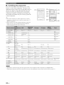
to exit from "BASIC SETUP".
23
En
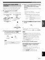
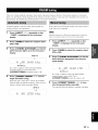
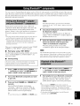
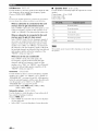
This unit is equipped with 13 preset SCENE templates for
various situations of using this unit. As the initial factory
setting, the following SCENE templates are assigned to
each SCENE button:
Press @INPUT
< It> (or press @AMP and
then @<_ / I:>) to select the desired template.
- _
SCENE 1: DVD Viewing
SCENE 2: Disc Listening
SCENE 3: TV Viewing
SCENE 4: Radio Listening
INPUT
Front panel
or
If you want to use other SCENE templates, you can select
the desired SCENE templates from the SCENE template
library and assign the templates to the selected SCENE
buttons on the front panel and the remote control.
Select
the desired
SCENE
template
Remote
.,©
SCENE
template
(Image)
library
3 seconds
3
Press the OSCENE
(or @SCENE) button
again to confirm the selection.
The selected SCENE template is assigned to the
button.
or
Front
panel
Remote
control
To cancel the procedure, press @AMP and then @RETURN.
3 seconds
or
Q
Front panel
Remote
Flashes
i,,.
En
control
F'_iiF'_ M='=
i_ 'i =:::,i i :i._ii?
i,i
Assign the
SCENE template
to the SCENE
button
Press and hold the desired @SCENE (or
@SCENE) button for 3 seconds.
The indicator on the selected SCENE button on the
front panel starts to flash, and the name of currently
assigned SCENE template appears in the front panel
display.
24
;:_
i = i,,.
ili_i
i=
ii
•
,
,,.
'_ =2:Li '_ i,":LJ
control
Once
the desired
corresponding
SCENE
SCENE
source of the SCENE
for details.
templates
buttons,
template
are assigned
to the
you may need to set the input
on the remote
control.
See page 28
•
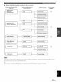
Which SCENE template would you like to select?
Which
source do you like to
play back?
(DVD video,
Recorded
video)
Video
sources
_,[
Which component
do you
like for playback?
SCENE
DVD
SA-CD or DVD-Audio)
Music discs (CD,
DVD Viewing
i
DVD Movie Viewing
]
DVD Live Viewing
]
DVR Viewing
]
Music Disc Listening
i
Disc Listening
]
CD Listening
]
CD Music Listening
]
I
Radi°
I
i
D°ck
DVD
co
TUNER
_{
Radio programs
_[
component
iPod or Bluetooth
i
(FM/AM)
[
DOCK
DTV/CBL
"_'_f TV programs
V-AUX
When
plays
iPod is connected
back the audio
Default SCENE
buttons
]_J/_J/_/_J/_
DVR
_/[
templates
to the Yamaha
sources
iPod universal
input at the DOCK
dock
or a Bluetooth
component
Listening
Listening
]
TV Viewing
]
TV Sports Viewing
]
Game
]
is connected
Playing
to the Bluetooth
adapter,
this unit
terminal.
_%,._
You call create
your
original
SCENE
templates
by editing
the preset
SCENE
templates.
See page 27 for details.
25
En
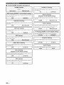
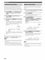
•
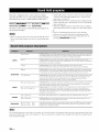
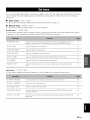
Preset SCENE template descriptions
I
CD Music Listening
Select this SCENE template
your CD player.
Input
source
I
Playback
mode
"a,hen you play back music discs on
I
CD
J
2ch Stereo
DVD Viewing (SCENE 1 as the default setting)
Select this SCENE template
on your DVD player.
"a,hen you play back general
Radio Listening
(SCENE 4 as the default setting)
contents
Select this SCENE template
DVD
1
STRAIGHT
TUNER
DVD Movie Viewing
Select this SCENE
DVD player.
template
DVD
J
when you play back movies on your
1
Movie
"a,hen you enjoy FM or AM radio
programs.
Music
Enh. 5ch
Dock Listening
Select this SCENE template "a,hen you play back nmsic on your
iPod stationed in a Yamaha iPod universal dock or Bluetooth
Dramatic
component
that is connected
to the Bluetooth
adapter.
DVD Live Viewing
DOCK
Select this SCENE
your DVD player.
temphtte
1
Pop/Rock
Select this SCENE template
DTV/CBL
DVR Viewing
Select this SCENE template
digital video recorder.
DVR
when you play back movies on your
1
Movie
template
DTWCB
when you play back music discs on
1
k
J
Select this SCENE template "a,hen you play back music sources
the back ground music on your DVD player.
as
5ch Stereo
CD Listening
Select this SCENE template when you play back music source
the back ground music on your CD player.
|
.L
26
En
TV Sports
"a,hen you play video games.
2ch Stereo
V-AUX
CD
"Mien you enjoy sports programs
Game Playing
Disc Listening
(SCENE 2 as the default setting)
1
STRAIGHT
TV Sports Viewing
Select this SCENE template
DVD
Enh. 5ch
"a,hen you enjoy TV programs.
J
Select this SCENE template
TV.
Dramatic
Music Disc Listening
DVD
Music
TV Viewing (SCENE 3 as the default setting)
DVD
Select this SCENE
your DVD player.
J
"a,hen you enjoy nmsic live video on
5ch Stereo
as
J
Game
on
2
Press @A /V to select the desired parameter
of the SCENE template and then @<1 / C> to
select the desired value of the selected
You can create your original SCENE templates for each
SCENE button. You can refer to the preset 13 SCENE
templates to create the original SCENE templates.
parameter.
You can adjust the following parameters for a SCENE
template:
•
Customizing the preset SCENE
templates
Use this feature to customize the preset SCENE templates.
Select the desired
template
SCENE
Create
an original
template
The input source component
The active sound field programs or STRAIGHT
mode
The night listening mode setting (see page 31 )
- SYSTEM: Keeps the current night listening
mode.
- CINEMA: Sets the night listening mode to the
CINEMA mode.
SCENE
- MUSIC:
SCENE
template
library
3
(Image)
Sets the night listening mode to the
MUSIC mode.
Press the @SCENE
the edit.
button again to confirm
©
Assign the SCENE
template to the SCENE
button
• An asterisk
SCENE
mark
(*) appears
by the name
of the original
template.
• To cancel the procedure, press @AMP and then @RETURN.
Press and hold the desired @SCENE button
for 3 seconds and then press @AMP.
The SCENE template customizing display appears on
the front panel display.
ONCE?
Q. Q
the SCENE
assigned
repeatedly
page 24),
template
you want
to any of the @SCENE
to recall
@SCENE buttons, you )nay need to set the input source of the
SCENE template on the remote control. See page 28 for details.
• You can create a customized SCENE template for each
@SCENE button, and if you create another customized
SCENE template, this unit overwrites the old customized
SCENE template with the new one.
• The customized SCENE template is only available for the
assigned @SCENE button.
3 seconds
When
• After changing the assignment of the SCENE template to the
the desired
to customize
button,
SCENE
is not
•
Renaming the SCENE templates
press @<:t / t::>
template
(see
Select SCENE in step 2 of "Customizing
the
preset SCENE templates" and then press
(2) ENTER.
•
•
•
•
Press
Press
space
Press
Press
(_)A / V to select the desired character.
(_)<1 It:> to place "_" (underscore) under the
or the desired character.
@ NETURN to cancel the new name.
@ ENTER to confirm the new name.
27
En
•
Controlling
the input source
components
in the SCENE mode
You can operate both this unit and the input source
component by using the remote control. You must set the
appropriate remote control code for each input source in
advance
(see
page
53).
Press the desired @SCENE
remote control.
2
button on the
to control the input source component of the
selected SCENE template.
= SCENE
buttons
page
51 for details
28
En
control
the input
source
of the function
Setting input source of the customized
SCENE template
on the remote control
If you customize the input source of the selected SCENE
template, you must set the input source of the SCENE
template on the remote control to operate the input source
component correctly.
Press and hold the @SCENE
button and the
desired input selector button (@) for 3 seconds.
Press the desired buttons in the * area below
These
•
buttons
component.
of each
button.
See
Press
the
component.
@SCENE
button
again
to operate
the input source
Caution
Extreme
caution
back CDs encoded
encoded
should
be exercised
Rotate @VOLUME
(or press @VOLUME
+/-) to adjust the volume to the desired
output level.
6
Press @PROGRAM
<1/I> (or press @AMP
and then press @ PROG <1/c>) repeatedly to
select the desired sound field program.
The name of the selected sound field program appears
in the front panel display.
See page 34 for details about sound field programs.
in DTS. If you play back a CD
in DTS on a DTS-incompatible
you will only hear some unwanted
damage
your speakers.
Check
supports
CDs encoded
in DTS.
CD player,
noise that may
whether
your CD player
Also, check the sound
output level of your CD player before
CD encoded in DTS.
1
5
when you play
you play back a
Turn on the video monitor connected to this
,}
unit.
Currently selected surround field program
2
Press OSPEAKERS
repeatedly to select the
front speakers you want to use.
The respective speaker indicators lights up in the
front panel display.
Press @INPUT <1/I> repeatedly (or press
one of the input selector buttons (@)) to
select the desired input source.
The name of the currently selected input source
appears in the front panel display for a few seconds.
Available
DVR
input source
V-AUX DTV,_BLI_DVD MD/BO-R TURER CD
•r b1Z:::'
Zi"i" i_ r"_Zir"_
• Choose a sound field program based on your listening
preference, not merely on the name of the program.
• When you select an input source, this unit automatically selects
the last sound field program used with the corresponding input
source.
• Sound field programs cannot be selected when the component
connected to the MULTI CH INPUT jacks is selected as the
input source (see page 30).
• When PCM signals with a sampling frequency higher than 48
kHz are input, this unit is automatically set to the "STRAIGHT"
mode (see page 36).
• To display information about the currently selected input source
in the front panel display, see page 32 for details.
•
Guideto contents
Currently selected input source
When you want to...
Start playback on the selected component or
select a broadcast station.
• Refer to the operating instructions for the source
component.
• See page 37 for details about FM or AM tuning
instructions.
See
page
Adjust the tonal quality of the front speakers
31
Edit parameters of sound fiekt programs
35
Enioy the sources which have wide dynamic range at
night
31
Use headphones
30
Select a decoder to play back sources with
35
Set this unit to the standby mode automatically
33
29
En
ramq,'ggqi
•
Selecting the front speaker set
i!ii
i::
ii='
i!:i
i:iii
2_i:
iiiiii
i!,_="i"i:i
iii
i'iii::
:i:
_2,,:,,"i
iiii
,i_l
iiiiii
llllllllllllllllllllllllllI
iiiiiiiiiiiiiiiiii........
•
Using your headphones
Connect a pair of headphones with a stereo
analog audio cable plug to the PHONES jack on
the front panel.
Press OSPEAKERS
repeatedly to turn on or off
the set of front speakers connected to the FRONT
A or FRONT B speaker terminals.
The active front speaker set changes as follows:
-)FRONT
Turn
off the volume
speaker
•
A-----_FRONT
OFF
(
level
of this unit when
you set "FRONT
you can use the speakers
speaker
• When you connect headphones,
speaker terminals.
Muting the audio output
Press @MUTE to mute the audio output.
Press
(_)MUTE
the front
terminals
B" to "ZONE
connected
in another
room
B" (see page 45),
to the FRONT
B
(Zone B).
Press @SPEAKERS
on the front panel
repeatedly to turn on or off the Zone B speakers.
When you activate the Zone B speakers, all the speakers in
the main room are muted.
no signals are output at the
• All Dolby Digital and DTS audio signals are )nixed down to the
left and right headphone channels.
•
you switch
setting.
Using the Zone B feature
When
When you select a sound field program, SILENT CINEMA mode
is automatically activated (see page 36).
B 1
again to resume
the audio output.
_%,._
• You call also rotate (_VOLUME (or press @VOLUME +/-) to
resume the audio output.
• You can adjust the muting level by using "MUTE TYP." in
"SOUND MENU" (see page 48).
• The MUTE indicator flashes in the front panel display when the
audio output is muted and disappears from the front panel
display when the audio output is resumed.
• You cannot activate both the main room and Zone B speakers
simultaneously.
• If you select CINEMA DSP sound field program and activate
the Zone B speakers, Virtual CINEMA DSP activates
automatically (see page 36).
•
Selecting the component connected to
the MULTI CH INPUT jacks as the input
so u rce
Use this feature
MULTI
source.
to select the component
CH INPUT
jacks
(see page
connected
to the
17) as the input
Press @INPUT </b>
repeatedly (or press
@AMP and then press @MULTI CH IN) so that
"MULTI CH" appears in the front panel display.
Use "MULTI CH SET" menu in "INPUT MENU" to set the
parameter for MULTI CH INPUT (see page 49).
• The input signals are amplified and output directly without
sound processing. Therefore, you cannot activate sound field
programs, the night listening )node, etc. while MULTI CH is
selected as the input source.
• When headphones are used, signals are output only from the
front left and right channels.
30
En
i,trl,/,'_:
•
Selecting audio input jacks
(AUDIO SELECT)
This unit comes with a variety of input jacks. Use this
feature (audio input jack select) to switch the input jack
assigned to an input source when more than one jacks are
assigned to an input source.
--'4'-• We recommend setting audio input jack select to "AUTO" ill
most
cases.
• You can adjust the default audio input jack select of this unit by
using "AUDIO SELECT" ill "OPTION MENU" (see page 50).
Press QAUDIO
SELECT (or press @AMP and
then @AUDIO SEL) repeatedly to select the
desired Audio input jack select setting.
=%
="' V" _
=._
H ,..2) _ZL..;:
Audio
:"dF'r':":
::,..,:...,
H LJ _ LJ5__
This feature
is not available
to the currently
when
selected
no digital
input jack
are
input source.
•
Selecting the night listening mode
The night listening modes are designed to improve
listenability at lower volumes or at night.
Press @AMP and then press _NIGHT
repeatedly to select "NIGHT:CINEMA"
or
"NIGHT:MUSIC".
Choices: NIGHT:CINEMA,
NIGHT OFF
Press @<1 It> to adjust the effect level while
"NIGHT:CINEMA"
or "NIGHT:MUSIC"
is
displayed in the front panel display.
Choices: MIN, MID, MAX
• Select "MIN" for minimum compression.
• Select "MID" for standard compression.
• Select "MAX" for maximum compression.
-4'-"NIGHT:CINEMA"
stored
and "NIGHT:MUSIC"
adjustments
are
independently.
• You cannot use the night listening modes in the following cases:
- when the component connected to the MULTI CH INPUT
jacks is selected as the input source.
- when headphones are connected to the PHONES jack.
- when the sampling frequency of the input sources are higher
than 96 kHz.
• The night listening modes may vary in effectiveness depending
on the input source and surround sound settings you use.
input jack select setting
Automatically selects input signals in the
following order:
( 1) Digital signals
(2) Analog signals
Selects only analog signals. If no analog
signals are input, no sound is output.
:::::::..,,..,,..:
assigned
=%_ E'T' =%
2
NIGHT:MUSIC,
•
Adjusting
the tonal quality
Use this feature to adjust the balance of bass and treble for
the front left and right speaker channels.
Press @TONE CONTROL repeatedly to select
"BASS" or "TREBLE" and then press
@PROGRAM
<1 It> to adjust the corresponding
frequency response level.
Control range: -10 to +10 dB
Control step: 2
• Select "BASS" to adjust the low-frequency response.
• Select "TREBLE" to adjust the high-frequency
response.
• Speaker and headphone adjustments are stored independently.
• If you increase or decrease the high-frequency or low-frequency
sound to an extreme level, the tonal quality of the surround
speakers may not match that of the front left and right speakers.
• Select "NIGHT:CINEMA" to reduce the dynamic
range of film soundtracks and make dialog easier to
hear at lower volumes.
• Select "NIGHT:MUSIC" to preserve
ease-of-listening for all sounds.
• Select "NIGHT OFF" if you do not want to use this
feature.
When
a night listening
indicator
lights
mode
is selected,
up in the front panel
the NIGHT
display.
31
En
•
Adjusting speaker levels during
playback
Youcan adjust the output level of each speaker while
listening to a music source.
•
Displaying the signal information
You can display the format, sampling frequency, channel,
bit rate and flag data of the current input signal.
Press @AMP and then press @MENU
the remote control.
This operation will override the level adjustment made ill "SP
LEVEL" (see page 46).
"BASIC SETUP" appears in the front panel display.
.. i:::,""!,:::'T !"'
"
1
Press @AMP and then press @LEVEL
repeatedly to select the speaker you want to
adjust.
=.iii;
W{:::'{:;?.
Subwoofer
SUP.=:{...
Surround left speaker
=.i:i;U{:4'.
=:{:;?.
Surround right speaker
....=!,,,. | =,,,=!
The following information about the input source
appears in the front panel display.
_%,-_
Once you press @ LEVELon the remote control, you can
also select the speaker by pressing @A / V.
2
,:::'i:::'"r'i i i:::,
Press @A /_7 to switch the displayed
information.
{:::'{:;?.(){".{T
{:;?. Front right speaker
Center speaker
L,,=!"i .,,,= ,;, =,,,'
Press @A / _7repeatedly to select "SIGNAL
INFO" and then press @ENTER.
{:::{:4:(){..{T
{..
Front left speaker
(.i:[:il
{".{
"i"[iil
{:4:
Format
Signal t_mmt.
Sampling
frequency
The number of samples
Channel
The number of source channels
signal (front/surronnd/LFE).
Bit rate
The number of bits passing
per second.
Flag data
Flag data encoded in DTS, Dolby Digital,
or PCM signals that cue this unit to
Press @<:1 It> on the remote control to
adjust the speaker output level.
The control range is from -10 dB to +10 dB.
from a continuous
signal.
automatically
_%,._
You can press @AIBICIDIE to select a speaker and then
(_)PRESET/TLINING <1 / t> to adjust the speaker output level.
32
En
on
4
Press @MENU
to exit.
per second
taken
signal to make a discrete
in the input
a given point
switch decoders.
i/Or,TYro:
•
Using the sleep timer
Use this feature to automatically set this unit to the
standby mode after a certain amount of time.
Press @AMP and then press _SLEEP
repeatedly to set the amount of time.
Each time you press _SLEEP, the front panel display
changes as shown below.
•
Playing video sources in the
background
You can combine a video image from a video source with
sound from an audio source. For example, you can enjoy
listening to classical music while viewing beautiful
scenery from the video source on the video monitor.
Press the input selector buttons (@) on the
remote control to select a video source and then
an audio source.
The SLEEP indicator flashes while you are switching the
amount of time for the sleep timer. Once the sleep timer is
set, the SLEEP indicator lights up in the front panel
display, and the display returns to the selected sound field
program.
• To cancel the sleep timer, press _SLEEP on the remote
control repeatedly until "SLEEP OFF" appears ill the front
panel display.
• You can also cancel the sleep timer setting by pressing
QSTANDBY/ON (or _STANDBY) to set this unit to the
standby mode.
Video
sources
Audio
sources
MULTI CH IN
33
En
This unit is equipped with a variety of precise digital
decoders that allow you to enjoy multi-channel playback
from almost any stereo or multi-channel sound source.
• Sound
input
• When
Press OPROGRAM
then press @PROG
<1 It:> (or press @AMP
<1 It:> repeatedly).
)node
• When
source
PCM
you select
MUSIC
ENTERTAIN
MOVIE
all input source,
field
program
this unit atttomatically
used with
the corresponding
selects
(see page
signals
be selected
CH INPUT
when
jacks
the component
is selected
as the
30).
with
a sampling
frequency
this unit is atttomatically
higher
than 48
set to the "STRAIGHT"
(see page 36).
the sampling
frequency
of the input sources
not apply
are higher
any sound field
programs.
_%,._
a sound
preference,
the last sound
source.
cannot
than 96 kHz, this unit does
• Choose
• When
programs
to the MULTI
kHz are input,
and
The name of the selected sound field program appears in
the front panel display.
field
connected
• You can select
input
field program
not merely
"Music
based
on the name
on your listening
of the program
Enh. 2ch" and "Music
itself.
Enh. 5ch" by
pressing _ENHANCER repeatedly.
{:::'OF::...."I:I?.OC.I.:7
CINEMA DSP processing. This program presents an image ol pop, rock, or jazz live concert. The
sound field reproduces the spaciousness of a massive pavilion with an emphasis on the vividness of
vocals on file stage and solo instruments and the beats ol rhythm instruments.
ll.!!!_]. ].
CINEMA DSP processing. This sound lield is suitable lk,r classic and orchestral music. The
program uses data collected ill a large concer( hall in Munich. You can enjoy delicate and beautiful
reverberation and a majestic atmosphere.
•.i[.!:.!!717
CINEMA DSP processing. The sound field is suitable for jazz and lusion music.
11uses data collected in a lamous jazz club ill New York. You can enjoy cleat" reverberation.
(:.ii.!:.!!p'!_!::=
CINEMA DSP processing. You can enjoy dynamic and thrilling sound effecls as you play games.
The program lels you feel the depth and three-dimensional surrounding sounds ol the field where
you are playing, and oilers cinema-like surrounding sound elfecls for file scenes ol movies.
'ii.)
CINEMA DSP processing. You can enjoy sports relays broadcast in stereo and variety shows with
a live SOlllld envirollment. For sporls relays, the voices ol comnlenlalors and announcers come
clearly from the center; the cheers and atmosphere ill the sladium spread around within a
comfk>rtable range, and you call feel like as ilyou are ill the stadium.
'.i:.i;F::ODi:..:!:.!.
{vi('.)k
._J._!:.!=
'.i:.i;!:::'.!:.!!
('.i.J.OL.!:!:.:.
CINEMA DSP processing. The sound lield is suitable lot movies wida an emphasis on spectacular
sound effects, and is a perfect fit with a wide screen. The program reproduces a wide dynamic
range h'om minimmn sound effects to powerful sounds.
{"{,:v...,:i.,!? [) F.!:!ffq.!.!_
i:..:i.,:
CINEMA DSP processing. This sound field is also suitable lk)rmovies with an emphasis on
three=dimensional sound effects. It restrains reverberation to an moderate extent, but reproduces
sound effects and background music in a soil. three=dimensional manner with clarity and center
orientation ol voices as pivots.
2 C.I_ '.i:.i;i:..,!,!',!:!,O
Downmixes
5C.{"! '.i:.i:'iM:.!q"',!:.!'C
,
CINEMA DSP processing. Using this program increases
sound field suitable lk)rbackground music at parties.
multi-channel
sources to 2 channel or plays back 2-channel sources as they are.
STEREO
ENHANCER
ivh _.:::.; ,... i:::'v'd.", ")," i.",
',',",i"',i:[:"
:=,'
]:::"',7',...'.',...'.
= :'.::i]:::",...'.
Selecl these programs to play back compression artifacts (such as the MP3 lormat) in 2-channel or
5-cl ....... 1 stereo. This prog .......... 1......... your listening experi ..... by regenerating tl..... issing
! !L'!.:.:" .!, _.."
harmonics
The sound field programs
actual concert hall, music
front,
34
back,
En
the listening position range. This is a
left and right.
!..,! !! ! =
""%'!
!
in a compression
of this unit are recreations
of real-world
acoustic
venue, movie theater, etc. Thus, you )nay notice
artifact.
environments
made from precise measurements
taken in the
variations
in the strength of the reflections
coming from the
-'l,i,lt|,l[_lOlqlq,_,,_:
•
Selecting decoders for 2-channel
sources (surround decode mode)
Signals input from 2-channel sources can also be played
back on multi-channels.
Press @AMP and then press @SUR.
repeatedly to select a decoder.
DECODE
You can select from the following decoders depending on
the type of source you are playing and your personal
preference.
"-'4_"Initial settings are indicated in bold under each parameter.
For Pop/Rock, Hall, Jazz, Game, TV Sports,
Movie Spacious and Movie Dramatic:
DSP level
Function:
Choices:
: ..,.,,.,., .:..,.
{"'!":IU L,Ui.::!.!,
i..
Panorama
Dolby Pro Logic processing for any
Choices:
sources
F:'L.].i].i {"{o'...'
:].c"
r"d
"r "r _..._......
: .,.
!"!....!,
.!, !'!L.E:'.:..!,
i..
Dolby Pro Logic 1Iprocessing for
movie sources
Dimension
Function:
Dolby Pro Logic [I processing for
music
,"..........
._:,_:: :,..
Dolby Pro Logic [I processing for
game
Sotlrces
•
Editing sound fields parameters
You can enjoy good quality sound with the factory default
parameters. Although you do not have to change the initial
settings, you can change some of the parameters to better
suit the input source or your listening room.
While listening to a source, press @AMP
and then press @A /_7 to select the desired
parameter.
2
[;,
:[
MEi..iS :[
0i..i
Gradually adjusts the sound field
either towards the front or towards the
-3 (towards the rear) to +3 (towards
the front), initial setting is STD
(standard).
three front speakers to varying
degrees. A larger value adjusts the
center image towards the front left and
right speakers.
0 (center channel sound is output only
from center speaker) to 7 (center
channel sound is output only from
front left and right speakers), initial
setting is 3.
For Music Enh. 2ch and Music Enh. 5ch
Press @<1 It> to change the parameter
value.
Effect level
Function:
Choices:
You cannot change parameter values when "MEM.GUARD"
"OPTION MENU" is set to "ON" (see page 50).
Sends stereo signals to the surround
speakers as well as the front speakers
for a wraparound effect.
OFF, ON
Center width ..,.,,.:., : :.:. :.,, ,.:.,: :
Function:
Adjusts the center image from all
Control range:
1
F'F:!bK)i::;:
A1"i!:::!
rear.
SOI.IFCeS
Control range:
r"d "r "r
: :_, .:, .:,
Adjusts the effect level.
MIN, MID, MAX
For PRO LOGIC II Music:
Function:
:.,.,:.,.,,.,.,
r,,,:::c,_ _:::_
_:::_
L.'...q L..L.."."L..L..
EF:CL. L.i.,iL.
Adjusts the effect level.
LOW, HIGH
in
35
En
l,,'_.1,1.r, Iil_l'i
•
J,loi.;lqlll:
Using sound field programs without
surround speakers (Virtual CINEMA DSP)
Virtual
CINEMA
DSP programs
DSP allows
without
virtual speakers.
If you set "SUR.
CINEMA
select
LR"
LR" to "NONE"
CINEMA
"5ch Stereo"
- when
headphones
the CINEMA
by creating
whenever
SILENT
even when
"SUR.
cases:
34) is selected.
are connected
CINEMA
or movie
sources,
to the PHONES
jack.
through
allows you to enjoy multi-channel
sound,
including
ordinary
Dolby Digital
headphones.
SILENT
is automatically
activated whenever you connect
headphones
to the PHONES jack while listening
field programs
(except
(see page 34). When
SILENT
display.
36
you
Enjoying multi-channel sources and
sound field programs with headphones
(SILENT CINEMA)
music
En
CINEMA
for 2ch Stereo
SILENT
indicator
this unit is in the "STRAIGHT"
appropriate
processing.
sources
channels
2-channel
are decoded
mode,
straight
into the
without any additional effect
stereo sources are output from only
the front left and right speakers.
(see page 34).
(see page 45) ill the following
(see page
When
Enjoying unprocessed input sources
(Straight decoding mode)
multi-channel
(see page 47), Virtual
activated
DSP will not be activated
is set to "NONE"
- when
•
speakers
DSP is automatically
a sound field program
Virtual
you to enjoy
surround
•
and DTS
CINEMA
to sound
and Music Enh. 2ch)
CINEMA
is activated,
the
lights up in the front panel
Press @STRAIGHT
(or press @AMP and then
@STRAIGHT)
to select "STRAIGHT".
To deactivate the "STRAIGHT" mode, press
@STRAIGHT
(or @STRAIGHT) again so that
"STRAIGHT" disappears from the front panel display.
There are 2 tuning methods: automatic and manual. Automatic tuning is effective when station signals are strong and
there is no interference. If the signal from the station you want to select is weak, tune into it manually. You can also use
the automatic and manual preset tuning features to store up to 40 stations.
Automatic tuning is effective when station signals are
strong and there is no interference.
1
Press ®INPUT
"TUNER"
display.
2
If the signal received from the station you want to select is
weak, tune into it manually.
<1/I:> repeatedly so that
is displayed in the front panel
Press ©BAND
(FM or AM).
to select the reception band
Manually tuning into an FM station automatically switches the
tuner to monaural reception to increase the signal quality.
1
Press ®INPUT
"TUNER"
display.
Press OTUNING
AUTO/MAN'L
so that the
AUTO indicator lights up in the front panel
display.
Lightsup
<_ It> repeatedly so that
is displayed in the front panel
2
Press ©BAND to select the reception band
(FM or AM).
3
Press QTUNING
AUTO/MAN'L
so that the
AUTO indicator disappears from the front
panel display.
i:::i i:::ii."i'i,::i.,::i.i:::i
kH:::
No colon(:)
i:[:i
If a colon (:) appears in the front panel display,
automatic tuning is not possible. Press
(_)PRESET/TUNING
to turn the colon (:) oft'.
Press ©PRESET/TUNING
<1 It> once to
begin automatic tuning.
When this unit is tuned into a station, the TUNED
indicator lights up and the frequency of the received
station is shown in the front panel display.
Lights
up
i:[:iM 'i 4 4 i:::i i.:"H'::;"
No colon (:)
If a colon (:) appears in the front panel display,
manual tuning is not possible. Press
®PRESET/TUNING
to turn the colon (:) oft'.
4
Press ©PRESET/TUNING
<1 /t> to tune
into the desired station manually.
You can hold down the button to continue searching.
I
AUTO
T_N_
="_
i"i i'd
"_:'::::
":_"m'::.=i.. i...i...;.
37
En
iili_ii!]iii{ii_,_ii]iiiii_ii{iiil;_i:,:,:,:,!ii}iliiii_iiiiil
_ii_?_;_ii]iiii!i/ii!iiii
i_i_iii_i_i_
ii_;!;?_
ii'_ _";iil
!]ii}lii{ii]iiii}iiii!_i,_,i'ii:iiii!i!i}iiii/}i
You can use the automatic preset tuning feature to store
FM stations with strong signals up to 40 (A1 to ES: 8
preset station numbers in each of the 5 preset station
groups) of those stations in order. You can then recall any
preset station easily by selecting the preset station number.
1
<_/I>
Tune into a station automatically or manually.
repeatedly so that
is displayed in the front panel
2
Press @MEMORY.
The MEMORY indicator flashes in the front panel
display for approximately 30 seconds.
Press ©BAND
to select "FM" as the
reception band.
3
1
See page 37 for tuning instructions.
Press ®INPUT
"TUNER"
display.
2
You can also store up to 40 stations (AI to ES: 8 preset
station numbers in each of the 5 preset station groups)
manually.
Press @AJB/C/D/E
Press and hold @MEMORY
seconds.
for more than 3
The preset station number as well as the MEMORY
and AUTO indicators flashes. After approximately 5
seconds, automatic presetting starts from the current
frequency and proceeds toward the higher
frequencies.
and
@PRESET/TUNING
<1 / i> repeatedly to
select a preset station group and number (A1
to E8) while the MEMORY indicator is
flashing.
Check that the colon (:) appears in the front panel
display.
Flashes
Flashes
Preset station group and number
C?"i !!i:::'i','E!:::!7: E:::; H M..:=.
Flashes
When automatic preset tuning is completed, the front
panel display shows the frequency of the last preset
station.
You can select
the preset
station
group
and the preset
Press @MEMORY
station
number where the first received station will be stored by pressing
@AIBICIDIE and then @PRESET/TUNING <1 / t>.
• Any stored station data existing under a preset station number is
cleared when you store a new station under the same preset
station number.
• Only FM stations with sufficient signal strength are stored
automatically by automatic preset tuning. If the station you
want to store is weak in signal strength, tune into it manually
and store it as described in "Manual preset tuning" on this page.
m""":Y =; _".=M
The displayed
• Any stored
cleared
station
the station
En
station
station
when you
number.
• The reception
38
while the MEMORY
indicator is flashing.
The station band and frequency appear in the front
panel display with the preset station group and
number you have selected.
:::: ":Y_'::.= i.. L.i ...;.
has been stored
data existing
under
store a new station
mode
frequency.
(stereo
a preset
under
or monaural)
as C3.
station
number
the same preset
is stored
along
with
is
You can tune into any desired station simply by selecting
the preset station group and number under which it was
stored.
You can exchange the assignments of two preset stations
with each other. The example below describes the
procedure to exchange preset station "El" with "AS".
When
1
performing
@TUNER
this operation
to select
"TUNER"
with the remote
as the input
control,
press
source.
Select preset station "El"
and @PRESET/TUNING
using @AIBIClDIE
<1 / I>.
See "Selecting preset stations" on this page.
Press @A/B/C/DIE
(or @A/B/C/DIE
< / I>)
repeatedly to select the desired preset
station group (A to E).
2
The preset statkm group letter appears in the front
panel display and changes each time you press the
button.
Press @PRESET/TUNING
< It> (or
@PRESET/CH
A / V) to select the desired
preset station number (1 to 8).
The preset station group and number appear in the
front panel display along with the station band and
frequency.
ET'i ,: i:'M
L....,".
You can select
by pressing
:: i
the desired
the numeric
i ;
preset
buttons
'2:"?
:...: i
station
Press and hold ®PRESET/TUNING
for
more than 3 seconds.
"El" and the MEMORY indicator flash in the front
panel display.
Flashes
ET'i
=: i:'M
'D"?
:':::: ML.i...:.
Flashes
3
Select preset station "A5" using
@AIBIClDIE
and @PRESET/TUNING
<1/
:':::: ML.i-.:.
:; ....:
number
i i i i.::..
"AS" and the MEMORY indicator flash in the front
panel display.
See "Selecting preset stations" on this page.
(1 to 8) directly
Flashes
(@),
i:::i
!:::;i',i:::"
i"i :::)i:::i.. !:::i i"ib,i'::"
Flashes
4
Press _PRESET/TUNING
"EXCHANGE
display
El-A5"
again.
appears
and the assignments
in the front panel
of the two preset
stations
are exchanged.
39
En
Once you have stationed your iPod in a Yamaha iPod universal dock (such as the YDS-I 0+ sold separately) connected to
the DOCK terminal of this unit (see page 18), you can enjoy playback of your iPod using the supplied remote control.
Supported
iPod (Click
iPod nano
iPod
and Wheel)
iPod mini
Battery
charge
Your iPod battery
DOCK
terminal
feature
is automatically
charged
when your iPod is stationed
of this unit as long as this unit is turned
in a Yamaha
iPod universal
dock connected
to the
on.
Stationing your iPod to the Yamaha iPod universal dock
Once you station your iPod to the Yamaha iPod universal dock, "iPod connected" and the DOCK indicator appears in the
front panel display when "V-AUX" is selected as the input source.
V-AUX/DOCK
Select "V-AUX" or "DOCK" as the input source.
MENU/Cursor buttons (AIVI<It>)IENTER
Navigate the menu of your iPod.
• Press @NERO or @<:1 to move to the previous
menu level.
• Press (_)A/V to move to the upper/lower menu
level.
• Press (_ENTER or (_)t:> to move to the
subsequent menu, start playback of the selected
menu level, or change the selected setting.
Playback control buttons
Control the playback of the connected iPod.
[2>/[]1"1:
Play/pause
F-l: Stop
_/12>12> : Search backward/forward
1<1<1/124>t:Skip backward/forward
• Operations can be also done with the controls on your iPod. Refer to the instruction
iPod.
manuals of your iPod for the operations on your
• Some features may not be compatible depending on the model or the software version of your iPod.
• For a complete list of status messages that appear in the front panel display, see the "iPod" section in "Troubleshooting"
40
En
on page 58+
You can connect a Yamaha Bluetooth adapter (such as YBA-10, sold separately) to the DOCK terminal of this unit and
enjoy the music contents stored in your Bluetooth component (such as a portable music player) without wiring between
this unit and the Bluetooth component. You need to perform "pairing" the connected Bluetooth adapter and your
Bluetooth component in advance.
If the Bluetooth
terminal
Pairing must be performed when using a Bluetooth
component with the Bluetooth adapter connected to this
unit for the first time or if the pairing data has been
deleted. "Pairing" refers to the operation of registering a
Bluetooth component for Bluetooth communications.
panel
in the front
display.
5
Select the Bluetooth adapter in the Bluetooth
device list and then enter the pass key
"0000" to the Bluetooth component.
When the pairing procedure is successful,
"Completed" appears in the front panel display.
There are two pairing methods: pairing by using "START
PAIRING" in "SET MENU" and quick pairing.
The Yamaha
Bluetooth
other components.
ninth
data
•
to the DOCK
appears
Check that the Bluetooth component detects
the Bluetooth adapter.
If the Bluetooth component detects the Bluetooth
adaptel; "YBA-I 0 YAMAHA" (example) appears in
the Bluetooth device list.
• You only need the pairing operation for the first time that you
use the Bluetooth component with the Bluetooth adapter.
•
Pairing by using "SET MENU"
Use this feature to perform pairing with the video monitor.
Select "START PAIRING" in "INPUT MENU". See
page 50 for details.
is not connected
"No BT adapter"
4
-4'--
• Pairing requires operations on this unit and on the other
component with which Bluetooth communications are to be
established. If necessary, refer to the other component's
operating instructions.
adapter
of this unit,
component
When
adapter
pairing
and the pairing
for the least recently
used
can be paired
is conducted
data
with up to eight
successhllly
is registered,
other component
with a
the pairing
is cleared.
Quick pairing
To ensure security, a time limit of 8 minutes is set for the
pairing operation.
You are recommended to read and fully
understand all the instructions before starting.
1
Press @AMP and then press @INPUT
I> repeatedly (or press @V-AUX/DOCK)
select "V-AUX" as the input source.
2
Turn on the Bluetooth component you want
to pair with,
3
Press and hold @BAND
seconds,
(or @BAND)
<:1/
to
for 3
Once the Bluetooth adapter starts pairing,
"Searching..." appears for a moment. While the
Bluetooth adapter is in the pairing mode, DOCK
indicator flashes in the front panel display.
-4'-To cancel the pairing, press (_)BAND (or @BAND) again.
1
2
and then press @INPUT
<:1/
I> repeatedly (or press @V-AUX/DOCK)
select "V-AUX" as the input source.
Press @AMP
to
Start playback of your Bluetooth component.
When the connected Bluetooth adapter detects the
Bluetooth component, "BT connected" and the
DOCK indicator appears in the front panel display.
-4'-• When you press @ENTER on the remote control, the
connected Bluetooth adapter searches and connect to the last
connected Bluetooth component. If the Bluetooth adapter
cannot find the Bluetooth component, "Not found" appears in
the front panel display.
• To disconnect the Bluetooth adapter from the Bluetooth
component,
press @ RETURN.
41 En
Recording adjustments and other operations are performed from the recording components. Refer to the operating
instructions for those components.
• When this unit is set to the standby mode, you cannot record between other components connected to this unit.
• The settings of TONE CONTROL (see page 31) and VOLUME settings, speaker levels (see page 32) and the sound field programs
(see page 34) do not affect recorded material.
• The source connected to the MULTI CH INPUT jacks on this unit cannot be recorded.
• Digital signals input at the DIGITAL INPUT jacks are not output at the analog AUDIO OUT (REC)jacks for recording. Therefore, if
your source component is connected to provide only digital signals, you cannot record the source.
• A given input source is not output on the same AUDIO OUT (REC) channel.
• The analog audio signals input at the DOCK terminal can be output at the analog AUDIO OUT (REC)jacks for recording.
• Once you have connected a recording component to this unit, keep the component turned on while using this unit. If the component is
turned off, this unit may distort the sound from other components.
• Check the copyright laws in your country to record from CDs, radio, etc. Recording of copyrighted material may infringe copyright
laws.
Do a test recording before you start an actual recording.
If you play back a video source that uses scrambled or encoded signals to prevent it from being dubbed, the picture
itself may be disturbed due to those signals.
1
Turn on all the connected components.
2
Press (_INPUT
<1 / b> repeatedly (or press
one of the input selector buttons (_)) to
select the source component you want to
record from.
42
En
3
Start playback on the selected source
component or select a broadcast station.
4
Start recording on the recording component.
You can use the following parameters in set menu to adjust a variety of system settings and customize the way this unit
operates. Change the initial settings (indicated in bold under each parameter) to reflect the needs of your listening
environment.
•
Basic setup
Use
this
feature
•
Manual setup
Use
this
Sound
feature
iiii:!:::!:iii;
:[(:: :iii;Eii...iP
to automatically
and
system
parameters
(see
page
22).
adjust
speaker
and
system
parameters.
:i, :iii;Oi..ii..{i)i%i:i..{i.J
Use this menu to manually
compensate
speaker
i,i{:::{i..ii...i!:::!i...
:iii;E[i...iF:'
to manually
menu
adjust
for video signal
adjust
any speaker
processing
settings,
delays
alter the quality
and tone of the sound
when using LCD monitors
output
by the system
or
or projectors.
1:1[:''.i:.i;{:::'{i:.ii{:{{'::i{i:.ii{:'4'.
S{i:.ii"i"
Selects the size of each speaker, the speakers for low-frequency
signal output, the crossover
frequency, and the location of the front speakers connected to the FRONT B terminals.
45
{i:i',
::''.iii;{:::'
{_.{i:ili...i{i:ii{_.
Adjusts the
46
i..:)'.:..:,{...'L).L'.:'.:,! {"{{"{U{:..
Adjusts
the distance
D [:'('.i:{i:.ii{"{"i"{i:.ilR
(:.ii{i:.ili?
Adjusts
the tonal quality of the center
{i:.il
[:'L{:::'E {...{i:.ili...i{i:.ii{...
Adjusts
the output level of the LFE channel
1:':"
[:'[[:'=={:4'.{:::{{".{(iii{i
Adjusts
the dynamic
(.ii[;'1:::1]..]{[[:'
[[ ill) '.i.i;E"i
Adjusts
level.
the muting level, audio delay
output level of each speaker.
of each speaker.
range of Dolby
47
speaker.
47
for Dolby
Digital or DTS signals.
Digital or DTS signals.
settings,
maximum
47
volume
47
level and initial volume
48
Input menu 2 :[i".{i:::'ffTi"iiiii:i..ii.J
Use this menu to manually reassign the input jacks, select the input mode or rename the input source.
1:1[:'[[=i
{".{{:::'i.
ri" {:{'.i:.i:'.i:.i:
[[=i
(:.ii{"{
Assigns
{i:.i',
[;'[[=i
{"{{:::'{..]"i"
{:'4'.{i:.ii{".{{:::{{"{{ii" Changes
the input jacks on this unit according
to the component
to be used.
the name of the input source.
i.: )i...ii.i{..i. i{','{{:..:.! 1":'..L
{"{
Adjusts
the output volume
D [:'D{i:.iii['.X'.)[[){i:.ii{::4'.
{"{('.)
[[){i:.il
Selects the decoder mode for the sources
rear panel of this unit.
{i:.ii
[:'{"{]..]{..."i"
[[=i('.i:{"{'.i:.i;E"i
Select the video source played
INPUT jacks.
48
49
of each jack.
49
connected
in the background
to the DIGITAL
ofthe
sources
INPUT jacks on the
in put from the MULTI CH
49
49
43 En
_frr_fi'
Option menu
3 ()F'[ ]I()H MENU
Use this menu to manually adjust the optional system parameters.
1...1
)L ) .!.'.:::,{'L.H"_" '.:::,1:::.
!
Actiusts the brightness
ii:.i',
Z;
_Mii:.ilM('.)i::'?.Y
(:.iiLiAi::'?.iZ[)
Locks sound field program
i.: )!"!U!).!. U '.:';,!:';.L.!:';.L:
!
Designates
the default
to the DIGITAL
of the front panel display.
parameters
50
and other set menu settings.
50
audio input jack select setting mode for the input sources
INPUT jacks when you turn on the power
D Z;
_{:::'{:::{{:;;'.{:::{{"{
= Zi=i
{..{]
Sets all the parameters
of the sound field programs
{i:.il
Z;'{i:.i',L.U{i:.ii"['('.)
('.)T{"{
Pairs the connected Yamaha Bluetooth
Bluetooth component
(see page 41 ).
adapter
connected
50
of this unit.
to the initial factory
(such as YBA-10,
settings.
sold separately)
50
with a
50
•
Signal information
:iii;:[(iiii..i{:::{L
:[i..iF:O
Use this feature to check audio signal informatkm (see page 32).
Press _A
_ENTER
menu.
Use the remote control to access and adjust each
parameter.
The following menus appear in the front panel
display as you press (_)A / V repeatedly.
_.,$,._
You can change the set menu parameters while this unit is
reproducing sound.
I
Press @AMP and then press _MENIJ
the remote control.
•i
2 :[i'.iF:'i_Ti"iiiii:i'.iLi
":i:
7d:::"T'TTd...i
i',ii:::'i.dii
.,
.,:
: .=,,_,: : : ::_,: :,_,
,,E:i:::!:iii:31(i:
:iii:EUF::'
Press (_ A / _7to select "MANUAL
'": "': =":" :"':"
:=,..:l
,'.= =':l=..:l'.:=
3
Press _ENTER
Press _A
_ENTER
submenu.
SETUP".
':::_i:::"'T"i i i::::
to enter "MANUAL
'::::Ni ii...ii"_i',ii:::'i.dii
on
"BASIC SETUP" appears in the front panel display.
2
/V repeatedly and then press
to select and enter the desired
/V repeatedly and then press
to select and enter the desired
• Repeat this step to navigate to and enter the items
you want to adjust.
• To return to the previous menu level, press
@RETURN.
SETUP".
"1 SOUND MENU" appears in the front panel
display.
Press (_A /_7 to select the desired parameter
and then (_<1/t>
to change the parameter
value.
3. :iii;OUi".!i)i0!Ei'.!U
• Press (_)t:> to increase the value.
• Press (_)<:1 to decrease the value.
7
44
En
Press (_MENU
to exit from set menu.
Woofer
section
of a speaker
is 16 cm (6.5 in) or larger:
section
of a speaker
is smaller
large
Use this menu to manually
compensate
LCD monitors
•
adjust any speaker settings or
for video signal processing
Use this feature
to manually
B speaker
Front speakers
!:::!
;,'iii;i:::'iiiii!:::!b:i[ii?:;?.
'iii;[iiTi
adjust
setting
any speaker
when the FRONT
B speakers
When the front speakers are large
speakers
muted
off and FRONT
including
terminals
headphones
sound is output
terminals
when
• ff a DSP program
to the PHONES
when
B", this unit automatically
DSP mode
at the FRONT
jack
(see page
36).
"FRONT
enters
OUT"
is set to "FRNT"
"LARGE"
automatically
in "FRONT".
other
than "LARGE"
changes
(see page 46), you can
ff the value
of "FRONT"
in advance,
this unit
is
the value to "LARGE".
B
on this unit,
the
B
B" is set to
the Virtual
"BASS
only
set to a setting
in the main zone are
sound
When
select
on, all the
from both headphones
and the FRONT
"FRONT
B" is set to "ZONE B".
is selected
When the front speakers are small
Select "SMALL" (small).
zone.
only.
• ff you connect
"ZONE
B is turned
the subwoofer
and this unit outputs
Select "LARGE" (large).
A and B on and off
are set in the main
Select "ZONE B" if the speakers connected
to the
FRONT B terminals are set in another zone. If FRONT
A is turned
SMALL
settings.
i:::i::?.0i..iTiiii',
Choices: FRONT, ZONE B
• Select "FRONT" to turn FRONT
!...!...::Lm.!!
Choices: LARGE,
Use this feature to select the location of the front speakers
connected
to the FRONT B terminals.
•
than 16 cm
(6.5 in): small
or projectors.
Speaker settings
FRONT
Woofer
delays when using
CINEMA
Center
speaker
Choices:
NONE,
i "i... i..i
:.,,,!.,,.! '!
i i... i.J
! !..,!',,
........................
SML
LUG
When the center speaker is large
Select "LRG" (large).
When the center speaker is small
Select "SML" (small).
When
you do not use the center
Select "NONE"
directed
speaker
The center channel
signals
are
to the front left and right speakers.
Surround
Choices:
(none).
left/right
NONE,
speakers
"" "'
.Z'i.i p:. =
' _'
!... p:.
SML, LRG
When the surround speakers are large
Select "LRG" (large).
When the surround speakers are small
Select "SML" (small).
When
you do not use the surround
Select "N()NE"
CINEMA
(none).
speakers
This unit is set to the Virtual
DSP mode (see page 36).
45
En
_frr{_fi'
LFE/Bass out
[.i:A:i.i?.iii;
()UT
Use this feature to select the speakers that output the LFE
(low-frequency effect) and the low-frequency signals.
Choices: SWFR, FRNT, BOTH
If you are not satisfied with the bass sounds from your speakers,
you call change these settings according to your preference.
When a subwoofer
is connected to this unit
and you want to get natural bass sound
Select "SWFR" (subwoofer). The LEE signals as well
as the low-frequency signals of other speakers set to
"SML" (or "SMALL") are directed to the subwoofer.
{:::'{...
When a subwoofer
is connected to this unit
and you want to get rich bass sound
Select "BOTH" (both). The low-frequency signals of
any source are output from the subwoofer. The LFE
signals as well as the low-frequency signals of other
speakers set to "SML" (or "SMALL") are directed to
the subwoofer. The low-frequency signals of the front
left and right channels are directed to the front left and
right speakers and the subwoofer regardless of the
"FRONT" setting (see page 45).
When you do not use a subwoofer
Select "FRNT" (front). The LFE signals, the
low-frequency signals of the front left and right
channels, and the low-frequency signals of other
speakers set to "SML" (or "SMALL") are all directed
to the front left and right speakers regardless of the
"FRONT" setting (see page 45).
Crossover
i"" !iD".,'..L..%,.'
i"i C" C:" '..'
i"i "..."
i ii:'iD
'..,
L, ! "..
Use this feature to select a crossover frequency of all the
speakers set to "SML" (or "SMALL") or to "NONE" in
"SPEAKER SET" (see pages 44 and 45). All frequencies
below the selected frequency will be sent to the subwoofer
or to the speakers set to "LRG" (or "LARGE") in
"SPEAKER SET" (see pages 44 and 45).
Choices: 40Hz, 60Hz, 80Hz, 90Hz, 100Hz, l l0Hz,
120Hz, 160Hz, 200Hz
Subwoofer phase :iii;kii:::i::;:
i:::q.,.i!:::!:iii;E
Use this feature to switch the phase of your subwoofer if
bass sounds are lacking or unclear.
Choices: NRM, REV
• Select "NRM" if you do not want to reverse the phase
of your subwoofer.
• Select "REV" to reverse the phase of your subwoofer.
46
•
Speaker
level ii.i:;,:iii;i:::'
L,iiii?.,.qi.i?.
Use this feature to manually adjust the output level of each
speaker.
Control range: -10 to +10 dB
Control step: 1 dB
Initial setting: 0 dB
En
Front left speaker
r'r",
!"!',:.
Front right speaker
C:
Center
S{....
Surround
left speaker
.:::,p:.
Surrotmd
right speaker
'::::i,
i:"
._...v:i i:::"
:..
S u bwoofer
,'" r",
The available
the speakers.
speaker
channels
speaker
differ depending
on the setting
of
•
,.....,.::,r..
_..._.._,...._:::.
Sp ea k er di stance
""" ""' L.,._..:,
""""'-'"''"'Use this feature to manually adjust the distance of each
speaker and the delay applied to the respective channel.
Ideally, each speaker should be the same distance from the
main listening position. However, this is not possible in
most home situations. Thus, a certain amount of delay
must be applied to the sound from each speaker so that all
sounds will arrive at the listening position at the same
time.
Unit
UH][T
Press
@A
/ V to select
the selected
Frontleft speaker
{:::P.(.){".{T{:;?.
Front right speaker
(.i:[:il{".{
'r [:il{:4:
Center
'.iii;U{:;?.
= L.
Surroundleft speaker
.::a..u',:.== !',:.
Surround
'.::@1...
1.,:'.
Subwoofer
and @<:1 / 1::>to adjust
to make adjustments
while listening
Choices: OFF,
to a test tone.
ON
Select "OFF"
selected
•
asthe
'fE:iii;T
Use this feature
•
for "CENTER
to stop test tones and output
GEQ"
the currently
source component.
Select "ON"
to output
test tones from the center
and
front left speakers.
Speaker
distances
Control range: 0.30 to 24.00 m (1.0 to 80.0 ft)
Control step: 0.10 m (0.5 ft)
Initial setting:
FRONT L/FRONT R/SWFR: 3.00 m (10.0 ft)
CENTER: 2.60 m (8.5 ft)
SUR. L/SUR. R: 2.40 m (8.0 ft)
{:::P.(){".{T
L.
band
band.
Followingisan
example where"100Hz"isselected
frequency band.
Test tone
Choices: meters (m), feet (ft)
Initial setting:
[U.S.A. and Canada models]: feet (ft)
[Other models]: meters (m)
• Select "meters" to adjust speaker distances in meters.
• Select "feet" to adjust speaker distances in feet.
a frequency
frequency
•
Low-frequency
:.,... :
:.,..:-..
i...
i...i..,
I.=,=
ii
. )
l.ml
I.=,=
effect
level
: :.,..: ::.,..:
i
i...i
l.m
I.=,=
ii...i
"='
l.m
I
Use this feature to adjust the output level of the LFE
(low-frequency effect) channel according to the capacity
of your subwoofer or headphones. The LFE channel
carries low-frequency special effects which are only added
to certain scenes. This setting is effective when the input
signal contains the LFE channel.
Control range: -20 to 0 dB
Control step: 1 dB
Speaker LFE :iii;i:::'
L,i:::i
....
Adjusts the speaker LFE level.
speaker
Headphone LFE iii:::'L,i:::iii]
Adjusts the headphone LFE level.
right speaker
Depending on the settings of "BASS OUT" (see page 46), some
signals may not be output at the SUBWOOFER
The available
speaker
channels
differ
depending
on the setting
OUTPUT jack.
of
•
Dynamic range
i:::::,i]:,,,
i::i:!:::!i..iGii:.i;
Use this feature to select the amount of dynamic range
•
Center graphic equalizer
i:;:,::,_:;;:iiii;i..iiiiii;i:.:i:
(.iiiiii;(;! compression to be applied to your speakers or
Use this feature to adjust the built-in 5-frequency band
headphones. This setting is effective only when this unit is
(100Hz, 300Hz, lkHz, 3kHz and 10kHz) graphic
decoding Dolby Digital and DTS signals.
equalizer for the center channel so that the tonal quality of
Choices: MIN, STD, MAX
the center speaker matches that of the front speakers. You
• Select "MIN" (minimum) if you regularly listen at low
can make adjustments while listening to the currently
volume levels.
selected source component or a test tone.
• Select"STD" (standard) for general use.
• Select "MAX" (maximum) to preserve the greatest
Control range: -6.0 to +6.0 dB
amount of dynamic range.
Control step: 0.5 dB
the speakers.
Initial setting: 0 dB
Speaker dynamic range :iii;i:::'i),, i;:
Adjusts the speaker compression.
Headphone dynamic range
i...ii:::'
i),, i:,i:
Adjusts the headphone compression.
47
En
•
Audio settings
(iii;,#J[:,ii0 :ii;E[
Use this feature to adjust the overall audio settings of this
unit.
Mute type {,{i.j[E '[Y{:::',=
Use this feature to adjust how much the mute function
reduces the output volume (see page 30).
Choices: FULL,-20dB
• Select "FULL" to completely mute all the audio
output.
• Select "-20dB" to reduce the current volume by 20 dB.
Audio delay !:::!,=
[:,EL.!:::!Y
Use this feature to delay the sound output and synchronize
it with the video image. This may be necessary when
using certain LCD monitors or projectors.
Control range: 0 to 160 ms
Control step: 1 ms
Maximum volume
{"i!:::!::.::
i..i0i.....
Use this feature to set the maximum volume level. This
feature is useful to avoid the unexpected loud sound by
mistake. For example, the original volume range is
+16 dB to -80 dB. However, when "MAX VOL." is set to
-5 dB, the volume range becomes -5 dB to -80 dB.
Control range: +16 riB, +10 dB to -30 dB
Control step: 5 dB
The "MAX VOL." setting takes priority over the "Initial Volume"
setting. For example, if "INI.VOL." is set to -20 dB and "MAX
VOL." is set to -30 dB, the volume level is automatically set to
-30 dB when you turn on the power of this unit next time.
Initial volume
r_.._r _,,_
._,_ '_._. = "...'L.q.,., =
Use this feature to set the volume level when the power of
this unit is turned on.
Choices: Off, -80 dB to +16 dB
Control step: 1 dB
The "MAX VOL." setting takes priority over the "INI.VOL."
setting.
48
En
Use this menu to reassign the input jacks, select the input
mode or rename the input source.
•
Input assignment
Use this feature to assign the input jacks according to the
component to be used if the initial settings of this unit do
not correspond to your needs. Change the following
parameters to reassign the respective jacks and effectively
connect more components.
Once the input jacks are reassigned, you can select the
corresponding component by using (_)INPUT <:1/ t:> (or
the input selector buttons (@) on the remote control).
For DIGITAL INPUT COAXIAL jacks 1
•r L ;
.:1: :
..' 4 ".
,..:1 ..
Choices: (1) CD, MD/CD-R, DVD, DTVICBL, V-AUX,
DVR
For DIGITAL INPUT OPTICAL jacks 2 and 3
•r L ;
.:1: :
..' ,% ".
,. ,:,.,.,
•:. : :
.. ,.,:..
Choices: (2) CD, MD/CD-R, DVD, DTV/CBL V-AUX,
DVR
(3) CD, MD/CD-R, DVD, DTVICBL, V-AUX,
DVR
• You cannot select a specific item more than once.
• You cannot assign the same input source to both "IN (2)" and
"IN (3)". For example, you assign "CD" to "IN (2)", "
appears in "IN (3)".
•
Input rename
E:;,]IHi:::tFTAE]iAHEI
Use this feature to change the name of the input source
that appears in the front panel display.
The following is an example where "DVD" is renamed
"My DVD".
DVR
V-AUX
i)i..ii) +
1
DIV/CBL
_DVD
ND/GD-R
TUNER
CD
i)i..ii)
Press one of the input selector buttons (@)
or @MULTI CB IN to select the input
source you want to change the name of.
M D/CD-R
DVD
DTV/CBL
TUNER
•
MULTI¢H IN
or
F--]
0
Press @AMP and then press @ </t>
on the
remote control to place the "_" (underscore)
under the space or the character you want to
edit.
Press @A / V to select the character you
want to use and then press @< / t> to move
to the next space.
• You can use up to 8 characters for each input.
• Press @V to change the character in the following order,
or press @A to go in the reverse order:
A to Z, a space, 0 to 9, a space, a to z, a space, symbols (#,
*, -, +, etc.)
Decoder
5
Press @MENU to exit from "INPUT
RENAME".
E:I:,U0i....UHEI
'H::;:
iH
mode
r,
,,r,,cc,". _,,,r,,c
L" =r,,c,
." L"L,'.."..q.."L,_
_ _'..q.."L.,
Decoder select mode
Use this feature to designate the default decoder mode for
the input sources connected to the DIGITAL INPUT jacks
when you turn on the power of this unit.
Choices: AUTO, LAST
•
•
Select "AUTO" if you want this unit to automatically
detect the type of input signals and select the
appropriate decoder mode.
Select "LAST" if you want this unit to automatically
select the last decoder mode used the connected input
source.
DTS decoder prioritize setting
Choices: AUTO, DTS
• Select "AUTO" if you want this unit to automatically
detect input signal types and select the appropriate
input mode.
• Select "DTS" when you play back a DTS-CD.
•
Multi channel
:.., .. : :,..,:..,
BGV
Repeat steps 1 through 3 to rename each
input source.
trim
Press one of the input selector buttons (@) or
@MULTI
CB IN to select the input source you
want to adjust the level.
Choices: CD, TUNER, MD/CD-R, DVD, DTV/CBL,
V-AUX (DOCK), DVR, MULTI CH IN
Control range: -6.0 to +6.0 dB
Control step: 1.0 dB
Initial setting: 0.0 dB
•
DVR
Volume
Use this feature to adjust the level of the signal input at
each jack. This is useful if you want to balance the level of
each input source to avoid sudden changes in volume
when switching between input sources.
= .=,
...,: :
input setup
...,:..,
=
E:Eii.,.
i
Use this feature to select the video source played in the
background of the sources input from the MULTI CH
INPUT jacks.
Choices: LAST, DVR, V-AUK, DTV/CBL, DVD
Select "LAST" to set this unit to automatically select the last
selected video source as the background video source.
/
49
En
_frr_fi'
•
Bluetooth setting
Start
Use this menu to adjust the optional
system
parameters.
pairing
•
Display settings
Dim me r
!:::!
::,[;,ii :iii:PL;:#SET
Memory guard
Bluetooth
For details
the Bluetooth
component"
TM
adapter
and your
on page 41.
Select"START
PAIRING" in "BLUETOOTH"
Check that the Bluetooth component detects
the Bluetooth adapter.
If the Bluetooth component the Bluetooth adapter,
"YBA-10 YAMAHA" (example) appears in the
Bluetooth device list.
Select
the Bluetooth
When "MEM.GUARD" is set to "ON", you cannot select and
adjust any other set menu items.
device
list and then enter the pass
"0000"
on the Bluetooth
•
Once
Use this feature
select
(?::,!:::{i.j[;,i
0 :iii:ELE(Ti
to designate
Select "AUTO" if you want this unit to automatically
detect the type of input signals and select the
appropriate
•
Select "LAST"
select
source
•
return
•
to cancel
to the previous
Select "YES"
i;,::,i:::'!:::!R!:::!H
==:[i.i:[
to set all the parameters
to the initial factory
NO, YES
Select "NO"
the parameter
menu
of the sound
field
initialization
and
settings.
level.
to set all the sound
the initial factory
field parameters
to
settings.
• You cannot automatically revert to the previous parameter
settings once you initialize the sound field program parameters.
• You cannot separately initialize individual sound field
programs.
50
En
key
component.
the pairing
successfully,
To cancel the pairing, press @RETURN
"START PAIRING".
to exit from
appears.
4
Press @RETURN to exit from "START
PAIRING".
input
(see page 31 ).
Parameter initialization
programs
Choices:
in the Bluetooth
if you want this unit to automatically
the last input mode used for the connected
Use this feature
•
input mode.
adapter
_%.._
when you turn on the
power of this unit.
Choices: AUTO, LAST
•
this unit completes
"Completed"
the defimlt audio input jack
setting for the input sources
with
about the pairing,
and then press @ENTER to start pairing.
The connected Bluetooth adapter starts searching
Bluetooth components. "Searching..." appears in the
front panel display.
Memory guard i"iEi"i,=(iiiLi!:::!i::;:[)
Use this feature to prevent accidental changes to DSP
program parameter values and other system settings.
Choices: OFF, ON
• Select "OFF" to turn off the "MEM.GUARD" feature.
• Select "ON" to protect:
- sound field program parameters
- all set menu items
- all speaker levels
- SCENE template parameters
Audio select
Yamaha
sold separately)
To ensure security, a time limit of 8 minutes is set for
the pairing operation. You are recommended to read
and fully understand all the instructions before starting.
1
[ii:::,i"E:HOR9
(.iiUAR[;,
TM
the connected
(such as YBA-10,
component.
refer to "Pairing
i11:,
._.r
_"_._"_..__,._:::
_::,
to start pairing
adapter
your Bluetooth
Use this feature to adjust the brightness of the front panel
display.
Control range:-4 to 0
Control step: 1
• Press @<:1 to make the front panel display dimmer.
• Press @t:> to make the front panel display brighter.
•
:iii:i!:::!i::;:ii:::'!:::!
:[i::;:i:i".{(iii
Use this feature
Bluetooth
iiii::,iiii:L,Liii.iT00TH
• ff the connected Bluetooth adapter cannot find any Bluetooth
components, "Not found" appears.
• If a Bluetooth adapter is not connected to this unit, "No BT
adapter" appears.
In addition to controlling this unit, the remote control can also operate other audiovisual components made by Yamaha
and other manufacturers. To control your TV or other components, you must set up the appropriate remote control code
for each input source (see page 53).
•
Controlling this unit
Press @AMP to control this unit.
•
Controlling
a TV
Press @ DTV/CBL to control your TV. To control your
TV, set the appropriate remote control code for
@ DTV/CBL (see page 53).
*1
DTV/C B L
AMP--
ii
*2
iiii
iil
_1 These buttons always control this unit.
_2 These buttons control this unit only when @AMP
is pressed.
_1 These
buttons
always
you press @DTV/CBL
control
your
TV regardless
TV POWER
Turns on or off the power.
TV CH +_
Changes
TV VOL +/
of whether
or not.
Increases
the channel
or decreases
number.
the volume
level.
TV INPUT
Changes
the input source.
TV MUTE
Mutes the audio output.
_2 These buttons control your TV only when @DTWCBL is
pressed. For details, see the "Digital TV/Cable TV" column on
page 52.
_%,._
You can control more than one TV by setting the appropriate
remote control code for any input source selector buttons other
than @DTV/CBL
In such a case, you can control the buttons
highlighted above (*1 and *2) when you press the input source
selector button.
51
En
•
Controlling other components
Press one of the input selector buttons (@) or A to E
buttons to control othercomponents. You must set the
appropriate remote control code for each input source in
advance (see page 53). The following table shows the
function of each control button used to control other
5
[2]""""L
[1]--
components assigned to each input selector button. Be
advised that some buttons may not correctly operate the
selected component.
[4],,,,,,,,,,,,r
_%,._
• The remote
control
components
different
• When
has 13 modes
so that the remote
(input
control
areas)
C51E2_CX3[Z2i
to control
call operate
up to 13
components.
you press
one of the optional
buttons
(A to E), you can control
without
changing
the input source
[1]
AV POWER
Power 'rq
[2]
TITLE
Title
[3]
PRESET/CH/_
PRESET/CH
V
component
the desired
control
area
component
of this unit.
Pow,'er 'r:1
Pow,'er 'r:2
Power '_1
Pow,'er 'r:[
Power '_ 1
Up
VCR channel up
Up
Preset up (1-8)
Down
VCR channel
down
Down
Preset down
(1-8)
Band
AIBIC/D/E <_
Left
Left
Preset down
(A-E)
AIBIC/D/E _:>
Right
Right
Preset up
(A-E)
ENTER
Enter
Enter
[4]
RETURN
Return
Return
[5]
REC
Disc skip
tplayer)
Rec trecorder)
Rec
Rec '_:2
Play
Play
Play '_2
Search
backward
Search backward
Searchbackward
'_2
[2>12>
Search forward
Search forward
Illl
Pause
Pause
[2>
Disc skip
Rec
Play
Play
Play
Search backward
Search backward
Search backward
Search lorward
Search [i_rward
Search forward
Pause '_2
Pause
Pause
Pause
Skip backward
Search forward
]<I<_
Skip backwaM
Skip backward
Skip backward
'_2
Skip backward
Skip backward
[2>{2>t
Skip forward
Skip forward
Skip forward '_2 Skip forward
Skip forward
Skip lorward
[]
Stop
Stop
Stop '_2
Slop
Stop
Stop
[6]
1-9, 0, +10
Numeric
Numeric btlnolls
Numeric btlnolls
Numeric buttons
Numeric btlnolls
Numeric buttons
[7]
MENU
Menu
[8]
DISPLAY
Display
Display
Display
Display
Display
Display
[9]
ENT
Title/1 ndex
Enter
Enter
Chapter/Time
Index
Index
*1 This button
_2 These
52
En
buttons
is operational
operate
your
btlnolls
Preset stations
(1-8)
Menu
only when
DVD
the original
recorder
only
remote
when
control
supplied
you set the appropriate
with the component
remote
control
has a POWER
code for DVR
button.
(see page 53).
2
You can control other components by setting the
appropriate remote control codes. For a complete list of
available remote control codes, refer to "List of remote
control codes" at the end of this manual.
Press the numeric buttons (0 to 9) (@) to
enter the four-digit remote control code for
the component to be used.
When the setting succeeds, "RemoteSetup OK"
appears; however, when it dues not, "RemoteSetup
NG" appears in the front panel display.
Remote control code default settings
CD
• ff the manufacturer of your component has more than one code,
try each of them until you find the correct one.
• If you do not press any buttons within 30 seconds in step 2, the
setup process is canceled. If this happens, repeat the setup
procedure.
CD
Yamaha
5013
MD/CD-R
CD-R
Yamaha
5001
TUNER
TUNER
Yamaha
5007
DVD
DVD
Yamaha
2000
DTV/CBL
--
--
--
V-AUX/D
OCK
TUNER
Yamaha
5011
DVR
DVR
Yamaha
2011
A
TUNER
Yamaha
5012
B
TUNER
Yamaha
5009
Q
5017
While holding
down
C
TUNER
D
--
--
--
E
--
--
--
You may not be able to operate
Yamaha
remote
try setting
control
another
Yamaha
your Yamaha
code is preset
Yamaha
remote
component
as listed above.
control
even if a
Ill this case,
code.
While pressing and holding one of the input
selector buttons (@) on the remote control to
select the input area you want to set up,
press @AV POWER for more than 3
seconds.
MD/CD-R
•
Resetting all remote control codes
Use this feature to clear all the remote control codes
previously set and reset all of them to the initial factory
settings.
1
2
While pressing and holding @AMP, press
@AV POWER for more than 3 seconds.
*
POWER
%
Press for 3
seconds
Press the numeric buttons (@) to enter the
code number "9981"
"RemoteSetup OK" appears in the front panel
display, and the remote control codes previously set
are cleared and reset to the initial factory settings.
_%,._
If you do not press any buttons within 30 seconds after
step 1, the clearing process is canceled. In this case, repeat
the clearing procedure.
TUNER
POWER
DVD
DTV/CBL
DVR
Press for 3
seconds
V.AU)gDOCK
©©©
While
holding
down
53
En
This unit has additional menus that are displayed in the
front panel display. The advanced setup menu offers
additional operations to adjust and customize the way this
unit operates. Change the initial settings (indicated in bold
under each parameter) to reflect the needs of your
listening environment.
•
Speaker impedance
:iii;i:::'i Mi:::'==
(U.S.A. and Canada models only)
Use this feature to set the speaker impedance of this unit
so that it matches that of your speakers.
Choices: 8_2MIN, 6f_MIN
• Select "8f2MIN" to set the speaker impedance to 8 _.
• Select "6f_MIN" to set the speaker impedance to 6 _.
• Only @STANDBY/ON, @PROGRAM
<1 / t> and
@STRAIGHT are effective while you are using the advanced
Front (A or B)
setup menu.
• No other operations call be made while you are using the
advanced setup menu.
• The advanced setup menu is only available ill the front panel
display.
8f2MIN
Center
The impedance
of each
speaker must be 8 f_ or
higher.
Surronnd
Front (A or B)
1
The impedance
Press @STANDBY/ON
on the front panel to
set this unit to the standby mode.
6f2MIN
Center
speaker
higher.
of each
must be 6 _Q or
Surronnd
2
Press and hold @TONE CONTROL and
then press @STANDBY/ON
to turn on this
unit.
This unit turns on, and the advanced setup menu
appears in the front panel display.
3
Press @PROGRAM
<1 /t> to select the
parameter you want to adjust.
The name of the selected parameter appears in the
front panel display.
4
Press OSTRAIGHT
repeatedly to change
the selected parameter setting.
5
Press OSTANDBY/ON
to confirm your
selection and set this unit to the standby
mode,
The settings
unit.
54
En
you made
are reflected
next time you turn on this
•
Tuner frequency
step
.....
i.j
(Asia and General models only)
Use this feature to set the tune]*frequency step according
to the frequency spacing in your area.
Choices: AM10/FM100, AM9/FMS0
• Select "AM 10/FM100" for North, Central and South
America.
• Select "AM9/FMSO" for all other areas.
•
Initializi ng i:::'i:.:;:E:i.i;ET
Use this feature to reset all the parameters of this unit to
the initial factory settings.
Choices: CANCEL, RESET
• Select "CANCEL" not to reset any parameters of this
unit.
•
Select "RESET" to reset the parameters of this unit.
• This setting completely resets all the parameters of this unit
including the set menu parameters. However, the advanced
setup menu parameters will not be initialized.
• The initial factory settings are activated next time you turn on
this umt.
Refer to the table below when this unit does not function properly. If the problem you are experiencing is not listed below
or if the instruction below does not help, turn off this unit, disconnect the power cable, and contact the nearest authorized
Yamaha dealer or service center.
•
General
This unit fails to turn
on or enters the
standby mode soon
after the power is
turned on.
The power cable is not connected
plug is not completely
inserted.
The speaker
incorrect.
Connect
the power cable firmly.
impedance
setting is
Set the speaker
circuitry
has been
Make sure that all speaker wire connections
on this
unit and on all speakers are secure and that the wire
for each connection does not touch anything other
than its respective connection.
11
This unit has been exposed to a strong
external electric shock (such as lightning
or strong static electricity),
Set this unit to the standby mode, disconnect
power cable, plug it back in after 30 seconds
use it normally.
--
Incorrect input or output cable
connections,
Connect the cables properly.
the cables may be defective.
No appropriate
been set.
Audio input jack select has
Set an appropriate
No appropriate
input source
Select an appropriate
The protection
activated,
No sound
or the
has been
selected.
Speaker
impedance
Audio
to match your speakers.
If the problem
input jack
input source
the
and then
persists,
select.
12
13-17
31
with
29, 30
@iNPUT
<:1 / C> on the front panel (or the input
selector buttons (@) on the remote control).
connections
are not secure.
Secure the connections.
The front speakers to be used have not
been selected properly.
Select the front speakers
The volume
Turn up the volume.
is turned clown.
The sound is muted.
Press @MUTE
11
with @SPEAKERS.
or @VOLUME
29
+/- on the remote
30
control to resume audio output and then adjust the
vohlme.
The sound
goes off.
suddenly
Signals this unit cannot reproduce are
being input from a source component,
such as a CD-ROM.
Play a source
unit.
Audio signals input at the HDMI jack are
not output from any speaker terminals.
Make an analog or digital
HDMI connection.
The setting of the connected
improper,
Make an appropriate setting following
manual of the connected component.
component
is
The protection circuitry has been activated
because of a short circuit, etc.
whose signals
can be reproduced
connection
Check that the impedance
the instruction
setting is correct.
The sleep timer has turned off this unit.
Turn on this unit, and play the source again.
The sound is muted.
Press @MUTE
Sou nd is heard
the speaker
side only.
from
Incorrect
cable connections.
on one
Connect
or @VOLUME
--
beside the
Check that the speaker wires are not touching
other and then turn this unit back on.
control
by this
--
12
each
+/- on the remote
30
to resume audio output.
the cables properly.
If the problem
persists,
13-17
the cables may be defective.
Incorrect
settings
in "SP LEVEL".
Adjust the "SP LEVEL"
settings.
32
55 En
iE'_m_'TE'T_IIEro
Only the center
When playing
speaker
CINEMA
outputs
substantial
a monaural
DSP program,
source with a
the source
_._
signal
_..._
front
and surround
speakers
outputandeffect
is directed
to the center
channel,
the
sound,
__
sounds,
No sound
is heard
from the center
x_
"CENTER"
"NONE".
in "SPEAKER
SET" is set to
Set "CENTER"
to "SML"
or "LRG".
45
speaker.
No sound
is heard
from the surround
Some sound field programs do not output
sounds from the center speaker.
Try another
"sun. LR" in "SPEAKER
"NONE".
Set "SUR.
SET" is set to
sound field program.
34
LR" to "SML" or "LRG".
45
This unit is in the "STRAIGHT'
mode
and a monaural source is being played
back.
Press @STRAIGHT
on the front panel so that
"STRAIGHT"
disappears from the front panel
display.
36
"BASS
Set "BASS
OUT"
to "SWFR"
46
Set "BASS
OUT"
to "BOTH".
speakers.
No sound
from
is heard
the subwoofer,
OUT" in "SPEAKER
SET" is set
to "FRNT" when a Dolby Digital
signal is being played.
or "BOTH".
or DTS
"BASS OUT" in "SPEAKER
SET" is set
to "SWFR" or "FRNT" when a 2-channel
46
source is being played.
The source
does not contain
low-frequency
Dolby Digital or DTS
sources cannot be
played. (Dolby Digital
or DTS indicator in
the front panel
display does not light
bass signals.
The connected component
is not set to
output Dolby Digital or DTS digital
signals.
Make an appropriate setting follo'Mng
instructions I_r your component.
Audio input jack select is set to
"ANALOG".
Set Audio
Incorrect
Connect
persists,
the operating
input jack select to "AUTO".
--
31
up.)
A humming
heard,
sound
is
cable connections.
the audio cables firmly. It" the problem
the cables may be detective.
The volume
level
cannot be increased,
or the sound is
distorted.
You are attempting to set the volume level
higher than the maximum volume level.
Adjust "MAX
The component connected to the AUDIO
OUT (REC)jacks
on this unit is turned
off.
Turn on the power of the component.
The sound effect
cannot be recorded,
It is not possible
with a recording
A source cannot be
recorded
by an
analog component
connected to the
The source component is not connected to
the analog AUDIO IN jacks on this unit.
Connect the source component
IN jacks.
"MEM.GUARD"
set to "ON".
Set "MEM.GUARD"
AUDIO
jacks.
VOL." setting.
--
48
--
to record the sound effect
component.
to the analog
AUDIO
15, 17
OUT (REC)
The sound
field
parameters
and some
other settings of this
unit cannot be
in "OPTION
MENU"
is
to "OFF".
50
changed.
This unit does not
operate
properly.
"CHECK SP WIRES"
appears in the front
panel display.
56
En
The internal microcomputer
has been
frozen by an external electric shock (such
as lightning or excessive static electricity)
or by a power supply with low voltage.
Disconnect the power cable from the AC wall outlet
and then plug it in again after about 30 seconds.
Speaker
Make sure all speaker cables
cables are short-circuited.
are connected
correctly.
11
,r/_q_f_lfP
There is noise
interference
from
digital or radio
frequency
equipment.
This unit is too close to the digital or
high-frequency
equipment.
The picture
The video source uses scrambled
is
disturbed,
encoded
This unit suddenly
enters the standby
mode.
The internal
the overheat
activated.
•
signals to prevent
Move this unit further away from such equipment.
--
Wait about 1 hour %r this unit to cool down and then
turn it back on.
--
or
dubbing.
temperature
is too high and
protection circuitry has been
Tuner
FM stereo reception is
noisy.
The characteristics
of FM stereo
Check the antenna
broadcasts may cause this problem
when the transmitter is too far away or
the antenna input is poor.
Try using a high-quality
antenna.
Use the manual
FM
There is distortion,
and
clear reception cannot
be obtained even with a
interference.
19
directional
FM
tuning method.
Adjust the antenna position
multi-path interference.
37
to eliminate
good FM antenna.
The desired station
cannot be tuned into
with the automatic
tuning
The signal is too weak.
Use a high-quality
Use the manual
directional
FM antenna.
tuning method.
37
method.
Previously preset
stations can no longer
be tuned into.
This unit has been disconnected
long period.
The desired station
cannot be tuned into
with the automatic
The signal is weak or the antenna
connections
are loose,
tuning
AM
There is multi-path
connections.
t_r a
method.
Set preset stations.
38
Tighten the AM loop antelma connections
and orient it for the best reception.
--
Use the manual
37
tuning method.
There are continuous
crackling and hissing
noises,
Noises result from lightning,
fluorescent lamps, motors, thermostats
and other electrical equipment,
Use an outdoor antenna and a ground wire.
This will help somewhat, but it is difficult to
eliminate all noise.
There are buzzing
whining noises.
A TV set is being used nearby.
Move this unit away from the TV set.
and
--
57
En
Ill case of a transmission error without a status message appearing ill the front panel display, check the connection to your iPod (see
page 18).
('.i:O!"!!"!_!:.!=C.'ii..
_!:.!=!"'!"'O!
....
There is a problem with the signal path
from your iPod to this unit.
; L,. _ .............
: r"_ .,..A
_..q"
!!':.!"!u_.,.q"! .!.!"_....:!
Tile iPod being used is not supported
Turn offthis unit and reconnect the Yamaha iPod
universal dock to the DOCK terminal of this unit.
Try resetting
by
:[ Pod
(" o !"!!"!_!':!=
(" "iM"=
c:i
L.' .!,:::.i...U r {{"U::q..• L.i::q.'!
iPod nauo, and iPod
--
mini are supported.
unitconnectionDOCKYDS-YamahaYour
isiPod
1complete.
0,terminal
iPod
sold
iSbetween
properly
universal
separately)
of this
your
stationed
clock
unit,
connectediPod
and
(such
and
inthe
athisas
to tile
Your iPod was removed
iPod universal
from a Yamaha
Station your iPod back in a Yamaha iPod universal
dock (such as YDS-10, sold separately) connected
the DOCK terminal of this unit.
dock (such as YDS-10,
sold separately) connected
terminal of this unit.
•
your iPod.
Only iPod (Click and Wheel),
this unit.
18
to the DOCK
18
to
Bluetooth
The Bluetooth adapter and the Bluetooth
component is in tile lniddle of the pairing.
The Bluetooth adapter and the Bluetooth
component is in the lniddle of establishing
the connection.
('.i:OV!F:"i _!:.!='ii.._!:.!=_:'.:i
Tile paring is COlnpleted.
('.I:.!:.!!!"!G_!:.!
=i _!:.!=C:i
Tile paring
_...:_ ,...,...,v.,v.,,:::=,...
"r,:::=,"._
I,H=
_
",H==,H=I
II
I=,H
=H=
"H==H
is canceled.
The connection
between
the galnaha
=HI
Bluetooth adapter (such as YBA-10, sold
separately) and the Bluetooth component
is established.
[) :[:!.i!.(2.O!"!!"!_!:'=('2.'h!:'=('.:i The Bluetooth component
is disconnected
from tile Bluetooth adapter (such as
YBA- 10, sokt separately).
_._,..,i"i""
_..,i:::'"r'_
.::_,.._.:a
r"""'i....,.....i.=..,::._.....,....
Tile Bluetooth adapter
the DOCK terminal.
58
En
is not connected
to
Connect the Yamaha Bluetooth adapter (such as
YBA-10, sold separately) to the DOCK termillal.
18
•
Remote control
The remote control
does not work nor
function
properly,
Wrong distance
or angle.
The remote control functions within a maximum
range of 6 in (20 It) and no more than 30 degrees
off-axis from the front panel.
Direct sunlight or lighting
inverter type of fluorescent
(from an
lamp, etc.) is
striking the remote control
unit.
sensor of this
The batteries
The remote
set.
are weak.
control
Reposition
Replace
code is not correctly
21
this unit.
all batteries.
Set the remote
remote control
3
control code correctly using "List of
codes" at the end of this manual.
Try setting another code for the same manufacturer
using "List of remote control codes" at the end of this
manual.
Even if the remote control
53
53
code is
correctly set, there are some models that
do not respond to the remote control.
•
Resetting the system
Use this feature to reset all the parameters of this unit to
the initial factory settings.
1
Press @STANDBY/ON
on the front panel to
set this unit to the standby mode.
Press and hold @TONE
CONTROL
then press @STANDBY/ON
unit.
and
to turn on this
• This procedure completely resets all the parameters of this unit
including the set menu parameters.
• The initial factory settings are activated next time you turn on
this unit.
To cancel
the initialization
any changes,
"CANCEL"
press
procedure
@STRAIGHT
at any time without
repeatedly
making
to select
and then press @STANDBY/ON
The advanced setup menu appears in the front panel
display.
Press @PROGRAM
"PRESET".
<1/t>
to select
Press @STRAIGHT
"RESET".
repeatedly to select
Select "CANCEL" to cancel the initialization
procedure without making any changes.
Press @STANDBY/ON
to confirm your
selection and set this unit to the standby
mode.
59
En
•
Audio information
DTS Digital Surround
Dolby Digital
Dolby Digital is a digital surround sound system that gives
you completely independent multi-channel audio. With 3
front channels (front LIR and center), and 2 surround
stereo channels, Dolby Digital provides 5 full-range audio
channels. With an additional channel especially for bass
effects, called LFE (Low Frequency Effect), the system
has a total of 5.1 -channels (LFE is counted as 0.1
channel). By using 2-channel stereo for the surround
speakers, more accurate moving sound effects and
surround sound environment are possible than with Dolby
Surround. The wide dynamic range from maximum to
minimum volume reproduced by the 5 full-range channels
and the precise sound orientation generated using digital
sound processing provide listeners with unprecedented
excitement and realism. With this unit, any sound
environment from monaural up to a 5.1-channel
configuration can be freely selected for your enjoyment.
Dolby Pro Logic II
Dolby Pro Logic II is an improved technique used to
decode vast numbers of existing Dolby Surround sources.
This new technology enables a discrete 5-channel
playback with 2 front left and right channels, 1 center
channel, and 2 surround left and right channels instead of
only 1 surround channel for conventional Pro Logic
technology. There are three modes available: "Music
mode" for music sources, "Movie mode" for movie
sources and "Game mode" for game sources.
Dolby
Dolby
Surround
Surround
to reproduce
(monaural),
realistic
analog
and dynamic
(stereo),
and a surround
(monaural).
sound within
frequency
widely used with nearly
sound
volume
60
En
system
frequency
range. Dolby
reproduced
digitizing
a digital
sound effects
or
audio signal,
In principle,
higher
per second
of quantized
range
is determined
the higher
the number
the number
of
is called the
of fineness
level into a numeric
when
value is called
bits. The range of rates that can
back is determined
while the dynamic
of quantized
while the degree
the sound
the range of frequencies
the
in Dolby Digital
and number
an analog
frequency,
difference
to enhance
moving
frequency
be played
stabilizes
a
systems.
times the signal is sampled
the number
that automatically
it only enforces
to the full-range
by the other 5 channels
Sampling
bits
sound
as well. The Dolby
The
PCM (Linear PCM)
Linear PCM is a signal format under which an analog
audio signal is digitized, recorded and transmitted without
using any compression. This is used as a method of
recording CDs and DVD audio. The PCM system uses a
technique for sampling the size of the analog signal per
very small unit of time. Standing for "Pulse Code
Modulation", the analog signal is encoded as pulses and
then modulated for recording.
sampling
all video tapes and laser discs,
bass signals.
is from 20 Hz to 120 Hz.
as 0.1 because
range compared
DTS 5. l-channel
converting
is
low-frequency
is counted
low-frequency
2 front
Surround
reproduces
range of this channel
This channel
for dialog
reproduces
built into this unit employs
system
on each channel
and directionality.
effects:
for special
channel
and in many TV and cable broadcasts
Pro Logic decoder
recording
a center channel
channel
The surround
a narrow
signal processing
LFE 0.1 channel
This channel
When
uses a 4-channel
left and right channels
effects
DTS digital surround was developed to replace the analog
soundtracks of movies with a 5.1 -channel digital sound
track, and is now rapidly gaining popularity in movie
theaters around the world. DTS, Inc. has developed a
home theater system so that you can enjoy the depth of
sound and natural spatial representation of DTS digital
surround in your home. This system produces practically
distortion-free 5. l-channel sound (technically, left, right
and center channels, 2 surround channels, plus an LFE 0.1
channel as a subwoofer, for a total of 5.1 -channels).
based on the sampling
representing
by the number
the sampling
of quantized
frequency,
that can be played
of quantized
sound level can be reproduced.
rate,
the sound level
bits.
the wider
back, and the
bits, the more finely the
•
•
Sound field program information
CINEMA
DSP
Since the Dolby
originally
Surround
designed
and DTS systems
for use in movie
were
theaters,
their effect
is best felt in a theater having many speakers designed
acoustic effects. Since home conditions,
such as room
size, wall material,
number
of speakers,
differ so widely,
it is inevitable
the sound heard.
Based on a wealth
data, Yamaha
technology
CINEMA
to combine
and DTS systems
movie
theater
and so on, can
that there are differences
of actually
DSP uses Yamaha
Dolby
to provide
in the listening
for
Pro Logic,
the audiovisual
in
measured
original
DSP
Dolby Digital
experience
of
room of your own home.
SILENT CINEMA
Yamaha has developed a natural, realistic sound effect
DSP algorithm for headphones. Parameters for
headphones have been set for each sound field program so
that accurate representations of all the sound field
programs can be enjoyed on headphones.
Video information
Component video signal
With the component video signal system, the video signal
is separated into the Y signal for the luminance and the PB
and Pr signals for the chrominance. Color can be
reproduced more faithfully with this system because each
of these signals is independent. The component signal is
also called the "color difference signal" because the
luminance signal is subtracted from the color signal. A
monitor with component input jacks is required in order to
output component signals.
Composite video signal
With the composite video signal system, the video signal
is composed of three basic elements of a video picture:
color, brightness and synchronization data. A composite
video jack on a video component transmits these three
elements combined.
Virtual CINEMA DSP
Yamaha has developed a Virtual CINEMA DSP algorithm
that allows you to enjoy DSP surround effects even
without any surround speakers by using virtual surround
speakers. It is even possible to enjoy Virtual CINEMA
DSP using a minimal two-speaker system that does not
include a center speaker.
61
En
AUDIO SECTION
VIDEO SECTION
• Minimum RMS Output Power I)r Front, Center, Surround
[U.S.A. and Canada modelsl
1 kHz, 0.9% THD, 8 f2 ...............................................
[Other models]
1 kHz, 0.9% THD, 6 f2 ...............................................
• Signal Level
Composite
• Maxinnnn Power (JEITA)
[U.S.A. and Canada modelsl
1 kHz, 10% THD, 8f2 ................................................
[Asia, China, Korea and General models]
1 kHz, 10% THD, 6f2 .................................................
• MAX
100 W/ch
100 W/ch
135 W/ch
135 W/ch
105 W or more
.................................................................
...................
• Video Maximum
1 Vp-p/75
1 Vp-p/75
f2 (Y), 0.7 Vp-p/75
f2
_C,(PI3/PI_)
Input Level ..................................
1.5 Vp-p or more
• Signal to Noise Ratio .................................................
50 dB or more
• Frequency
Power Per Channel
[U.K., Russia, and Europe models]
1 kHz, 0.7% THD, 4 f2 ......................................
Component
Response
Component
Signal
(MONITOR
OUT)
...................................
5 Hz to 60 MHz,
3 dB
FM SECTION
• Tuning Range
[U.S.A. and Canada models] ..........................
[Asia and General models] ......... 87.5/87.50
[Other models] ............................................
87.5 to 107.9 MHz
to 108.0/108.00
MHz
87.50 to 108.00 MHz
• 50 dB Quieting Sensitivity (IHF. 100% rood.)
Mono .................................................................
2.8 !iv (20.2 dBf)
• IEC Power
[U.K., Russia, and Europe models]
1 kHz, 0.1% THD, 6 f2 ........................................
• Dynamic
[U.S.A.
(IHE
[Other
(IHE
Power
and Canada models] (Impedance Selector: 8 _Q)
8161412 f2) .........................................
110113011601180
models]
61412 _Q) ....................................................
105/130150
• Dynamic Headroom [U.S.A. and Canada models]
8 _Q .....................................................................................
• Frequency Response
CD, etc. to Front .................................
V-AUX to Front ....................................
• Total Harmonic
(IHF-A
dB
dB
0.06% or less
0.06% or less
100 dB or more
98 dB or more
Front L/R ................................................................
170 _V or less
kHz)
60 dB/45 dB or more
BASS Boost/Cut ....................................................
TREBLE B oost/Cut ..............................................
• Headphone Jack Rated Output/hnpedance
CD, etc. (l kHz, 200 mV, 8 f-))....................................
• Input Sensitivity/Input
hnpedance
CD, etc ..................................................................
MULTI CH INPUT ...............................................
(EFFECT
ON)
.............
_+10 dB/100 Hz
_+10 dB/20 kHz
0.4 V1470 f2
200 mV/47
200 mV/47
kflkf2
2.0 V or more
• Output Level/Output
Impedance
AUDIO OUT (REC) ............................................
200 mV/l.2
SUBWOOFER
OUTPUT
(2ch Stereo and FRONT SP: SMALL) ....................
4 V/I.2
kf2
kf2
• Filter Characteristics
(fc=4016018019011001110112011601200
Hz)
H.P.E (Front, Center, Surround)
...................................
12 dB/oct.
En
• Tuning Range
[U.S.A. and Canada models] ..............................
[Asia and General models] ................. 530/531
[Other models] ....................................................
• Power Supply
[U.S.A. and Canada models] .............................
[Australia model] ...............................................
[Korea model] ....................................................
[China model] ....................................................
[U.K., Russia, and Europe models] .....................
[Asia and General models]
.............................................
110-1201220_40
530 to 1710 kHz
to 1710/1611 kHz
531 to 1611 kHz
........................................................
24 dB/oct.
120
240
220
220
230
V
V
V
V
V
AC,
AC,
AC,
AC,
AC,
60
50
60
50
50
Hz
Hz
Hz
Hz
Hz
V AC, 50160 Hz
• Power Consumption
[U.S.A. and Canada models] .................................
240 W/320 VA
[Other models] ....................................................................
240 W
• Standby Power Consumption
[Except Asia and General models]
• Tone Control
62
0.5%/0.5%
GENERAL
• Channel Separation
CD, etc. Input 5.1 kQ shorted (1 kHz/10
...................................................................
L.P.E (Subwoofer)
73 dB/70 dB
• Harmonic Distortion (1 kHz)
Mono/Stereo
................................................................
AM SECTION
Network)
• Maximum Input Signal
CD, etc. 1 kHz, 0.5%THD
• Signal to Noise Ratio (IHF)
Mono/Stereo
.............................................................
W
Distortion
• Signal to Noise Ratio (IHF-A Network)
CD, etc. (STEREO)
Input shorted
250 mV ................................................................
200 mV ..................................................................
Noise
W
0.41 dB
10 Hz to 100 kHz, 0_3
10 Hz to 20 kHz, 0_3
CD, etc. (2ch stereo) to Front SP OUT,
[U.S.A. and Canada models]
1 kHz, 50 W/8 _Q ...................................................
[Other models]
1 kHz, 50 W/6 _Q ...................................................
• Residual
90 W or more
......................................
• Maximum Power Consumption
[Asia and General models]
5ch, 10%/THD .................................................................
• Dimensions
• Weight
(W x H x D) ..................................
(17-1/8"
..............................................................
* Specifications
are subject
to change
0.8 W
530 W
435 x 151 x 318 mm
x 5-15/16" x 12-1/2")
8.0 kg (17 lbs 10oz)
without
notice.
•
Numerics
1 SOUND
Connecting
MENU
..........................
43, 45
2 INPUT MENU
............................
2ch Stereo ............................................
43, 48
34
3 OPTION
5ch Stereo
44, 50
34
•
MENU
.........................
............................................
A
Disconnected,
17
Bluetooth
Disconnected,
Connecting
a DVD
player
....................
15
Connecting
a DVD
recorder
.................
15
Connecting
a video
monitor
.................
15
Connecting
audio
Connecting
speakers
20
35
35
19
DSP level
19
DTS decoder
SET ...............................
............................................
45
48
Connecting
the power
.................
19
DVD
Live
Connecting
the
DVD
Movie
DVD
Viewing
......................................
26
DVR
Viewing
......................................
26
.....................................
47
Yamaha
levels
...................
31
............................................
terminals
............................
37
9
Connecting
CENTER
to the
terminals
13
Connecting
to the
.................................
plugs
................................
..........................................
...................................
9, 13
48
Connecting
GUARD
LEVEL
.......................................
SETUP
Basic setup
BASS OUT
........................
..............................
Connecting
Bluetooth
status
message
CH INPUT
Connecting
C)VOLUME
Canceled,
TRIM
Bluetooth
status
CD Listening
a TV
Controlling
other
49
Creating original SCENE templates
CROSSOVER
......................................
AUX
Crossover
•
17
..........................
.............
..................................
components
..............
..........................................
.................................
18
FRONT
B ............................................
45
15
FRONT
B speaker
45
51
Front panel
52
Front
46
35
setting
display
45
G)AUDIO
SET ....................................
Game ....................................................
48
34
Game
26
G
Playing
......................................
•
H
Hall
......................................................
34
..................................................
14
47
dynamic
Decoder
select
49
Headphone
LFE
speaker ......................................
width .........................................
equalizer
......................
DSP indicator
COAXIAL
jacks
DIGITAL
AUDIO
..............................
47
OPTICAL
jacks
DIGITAL
INPUT
...............................
20
Completed,
message
VIDEO
...................
jacks
.......... 9, 13
message
....... 58
COAXIAL
DIGITAL
DIGITAL
assignment
INPUT
INPUT
OPTICAL
DIMENSION
DIMMER
Dimmer
tuner
....................
15
49
AUDIO
jacks
13
13
.....................
48
..........................
9
assignment
......................
.......................................
Dimension
status
............................
26
45
45
35
......................
mode
48
35
............................................
35
.............................................
50
................................................
50
Disc Listening
......................................
20
......................................
•
speakers
...................
..............................
Headphone
DIGITAL
39
37
45
49
26
35
47
mode
...................
.............
..................
........................................
Decoder
message
35
20
F
50
20
......................................
decoders
stations
D)PARAM.
INI ....................................
Decoder indicator
.................................
49
..........................
49
FM tuning ............................................
FRONT
................................................
D
MODE
•
preset
D)DECODER
.............................
47
..............................
12
..... 27
46
..............................................
GEQ
Exchanging
50
sources
47
graphic
iPod controlling
jacks
2-channel
the standard
50
Center
Center
Connecting
a
cable TV/satellite
CH SET
.............................
Center
COMPONENT
Connect
error,
.....................................
................................
........................................
status
....................
Controlling
Listening
.............................
..............................................
Bluetooth
.................................
LEVEL
F)D.RANGE
43
46
...................
16
to the
D)CENTER
SELECT
................
video components
C
DISTANCE
..........
VIDEO
.......................
message
jacks
50
CT WIDTH
status
jacks
to the
Connecting
to the
SURROUND
terminals
BT connected,
Bluetooth
VIDEO
49
50
E)LFE
using
Connecting
..................................
16
or
46
.....................................................
setting
..........
22, 43
...........................................
..........................................
Bluetooth
jacks
E)MULTI
to the HDM[
MULTI
B)MEMORY
E)BLUETOOTH
VIDEO
COMPONENT
.........................
............................
E
Enjoying
50
......................................
RENAME
range
12
.........................................
B
•
26
.........................
select
37
12
26
..........................
Viewing
to the
B terminals
settings
.................................
Dynamic
49
.............................
Editing sound fields parameters
..........
ENHANCER
indicator
........................
Audio
tuning
..........................
18
.............
12
Audio
Automatic
...........
Viewing
setting
.........................
Connecting
FRONT
tuning
dock
18
prioritize
to the
A terminals
13
31
preset
...............
.............................................
Connecting
FRONT
Audio jacks ..........................................
AUDIO SELECT
.................................
Automatic
adapter
the
iPod universal
COMPONENT
48
cable
Bluetooth
Connecting
Yamaha
jacks
CINEMA
Front panel display
..........................
DSP LEVEL
........................................
...............
delay
CD Music
CENTER
11
................
cable
C)SP
50
the FM antennas
Audio
C)AUDIO
...... 58
the AM antennas
Audio
•
message
Connecting
AM tuning
ANTENNA
BGV
status
...................................
Connecting
the tonal quality
BASIC
settings
indicator,
58
48
playback
B)SP
17
iPod controlling
Display
DOCK
................
50
during
B)INPUT
.............
.............................
message
..............................
speaker
•
components
status
................................
Adjusting
AUDIO
.......................
SET
A)SPEAKER
A.DELAY
Adjusting
a CD player
ASSIGN
A)DISPLAY
A)INPUT
17
Connecting
a CD player and a
CD recordeffMD
recorder
................
26
HDM[
HDM[
jack,
HDM[
cable
range
plug .............
14
..................
47
...................................
47
Headphones
indicator
..........................
HP D.R ................................................
20
47
HP LFE
47
•
................................................
I
[nfl'ared
window
INI.VOL
Initial
....................................
..............................................
volume
Initializing
48
............................................
Input
assignment
Input
channel
speaker
48
.......................................
channel
Input
menu
Input
rename
48
and
indicators
Input
54
..................................
............................
indicators
......................
20
20
...........................................
43
........................................
49
63
En
[nput source indicators ......................... 20
[nput source information ...................... 32
Installing batteries ill the
remote control .................................... 3
iPod connected,
iPod controlling status message ....... 58
iPod control, Status message ............... 58
Rear panel
..............................................
Remote control codes ...........................
9
iii
•
Rename,
27
Unit
59
Unknown
SCENE
Resetting
•
the system
J
Jazz
.......................................................
•
L
LFE indicator .......................................
LFE/Bass out ........................................
20
46
Listening to unprocessed
input signals ..................................... 36
Low-frequency effect level .................. 47
•
.............................
SCENE
...................................................
7
status
message
Selecting
audio
input jacks
Selecting
preset
stations
Selecting
the MULTI
component
38
43
Manual
.......................
source
the SCENE templates
........... 24
...............................................
43
)node
Set this unit to the standby
)node
....... 31
......... 19
on the remote control
remote
control
codes
53
12
44
................................
...............................
44
36
indicator
20
Signal information
SILENT CINEMA
Maximum
48
SILENT
50
SLEEP
Memory
guard ......................................
Movie Dramatic
...................................
50
34
Sleep
Movie
34
Spacious
MULTI
....................................
CH INPUT
Multi channel
Multi-channel
programs
jacks
......................
input setup ....................
sources and sound field
with headphones
Multi-information
display
..............
....................
9
49
CINEMA
indicator
timer
Sound
Sound
SPA
................
...................................
...........................................
field programs
...........................
menu ..........................................
B indicators
SP D.R
.................................
..................................................
54
36
SP LFE
.................................................
47
20
Speaker
distance
...................................
47
.................................
47
distances
Speaker
dynamic
Music
Enh. 5ch
....................................
34
Speaker
impedance
MUTE
indicator
...................................
20
Speaker
level
........................................
46
MUTE
TYP ..........................................
48
Speaker
LFE
.........................................
47
48
Speaker settings ....................................
SPEAKERS
terminals
............................
45
9
20
Specifications
.........................................
START PAIRING
................................
50
31
Start pairing
50
N
NIGHT
Night
indicator
listening
..................................
)node
............................
No BT adapter,
Bluetooth
•
Straight
status
message
.................
58
Option
•
menu
........................................
44
P
Pairing,
Bluetooth
control
....................
PANORAMA
.......................................
41
35
Panorama
35
Parameter
PCM
.............................................
initialization
indicator
Placing
speakers
Playing
video
background
Pop/Rock
PRESET
Preset
•
Radio
64
........................
......................................
20
...................................
sources
templates
......................
En
phase
...............
..................................
Surround
left/right
speakers
.................
SWFR PHASE
.....................................
45
46
Volume
level
Trim
indicator
.......................
....................
.......................................
....................................................
Test tone
...............................................
B .................................................
47
47
Tuner
Tuner
54
20
34
54
Turning
off the power
..........................
Turning
on the power
...........................
frequency
indicators
TV Sports
TV Viewing
step ............................
...................................
.............................................
Viewing
..............................
..........................................
3
20
49
Z
Zone
T
TEST
33
26
VOLUME
............................
SELECTOR
9
55
54
26
20
indicator
VOLTAGE
46
3
45
•
VIRTUAL
36
Supplied accessories
..............................
SUR. LR ...............................................
TV Sports
....................................
jack
13
36
54
10
R
Listening
OUTPUT
13
9, 13
47
Troubleshooting
...................................
TU ........................................................
in the
......................................
..............................................
...............................................
SCENE
50
..............................
.......................................
SUBWOOFER
Subwoofer
O
........................
..........................................
mode
................................
...................................
47
Speaker
•
jacks
20
SP IMP .................................................
range
cable plugs
34
43
26
34
.............................................
30
33
Disc Listening
...........................
Enh. 2ch ....................................
type
21
.......................
20
Music
Music
Mute
...... 58
.....................
Video jacks ..........................................
Virtual CINEMA
DSP .........................
•
...............
................
37
48
................................
headphones
message
SCENE
43
.....................................
status
control
V
VIDEO
the night listening
........................................
volume
your
39
......... 30
Manual tuning ......................................
MAX VOL ...........................................
MEM.GUARD
Using
Video
CH INPUT
as the input
Setting the speaker impedance
.............
SIGNAL
[NFO .....................................
setup
the remote
31
Selecting
Set menu
Setting
47
iPod,
Using
•
...................
..................
Selecting
template
Manual preset tuning
...........................
MANUAL
SETUP ...............................
47
....
Setting input source of the customized
M
...................................................
......................................................
iPod controlling
Bluetooth
34
...................
S
Searching
•
template
U
UNIT
19
19
"@STANDBY/ON"
or "@ DVD"
(example) indicates the name of the
parts on the front panel or the remote
control. Refer to the attached sheet
26
or the pages at the end of this manual
for the information about each
26
position of the parts.
34
30
•
Front panel
•
Remote control
@
@
®
@
ii
List of remote control codes
MBO
Blu-ray player
Medi.....
Samsung
Micromaxx
Micromedia
2137
CD player
Yumaha
Microstar
5000, 5{113
Mitsubishi
Mizuda
CD Recorder
Must&
Yumaha
Naiko
5001
Onkyo
DVD
Orava
Acoustic Solutions
2078
Aiwa
2055, 2100
Akai
2096
P&B
Pacific
Panasonic
Akura
Alba
2076
2078, 2086
Philips
Apex
Awa
Axion
Brainwave
Bran&
Broksonic
Bush
Centrex
Classic
Clatronic
2027, 2049
2078
2078
2096
2073, 2085
2060
2075, 2078, 2112
2077
2078
2075
Pioneer
Proline
Provision
RCA
Coby
C-Tech
CyberHome
Daewoo
2078
2074
2025, 2079, 2091
2092, 2098
Sabaki
Samsung
Dansai
Daytek
DEC
Denon
Denver
Diamond
DK Digital
Dual
2096
2080, 2089
2075
2030, 21112, 2103
2075, 2076
2074
2094
2078
Sanyo
ScanMagic
Scientific Labs
Scott
SEG
Sharp
D-Vision
DVX
Elta
Euroline
2096
2074
2096
2096
Singer
Skymaster
Skyworth
SM Electronic
Red Star
Reoc
Roadstar
Rowa
Saba
Sansui
Silva
Funai
2052, 2058
Global Solutions2074
Sony
Global Sphere
Goodmans
Grundig
H&B
Haaz
HE
Hitachi
Home Electronics
Soundmaster
Soundmax
Standard
Star Cluster
Starmedia
Supervision
Sylvania
Synn
TCM
Teac
Tec
Technics
Teclmika
Technosonic
Tevion
Thomson
Tokai
Toshiba
2074
2075, 2077, 2078
2077, 2098
2075
2074
2078
2{)32, 2{)72
Kenwood
Kingavon
Koda
Lawson
Lenco
LG
Lifiztec
Limit
2078
2072
2134
2078
2033,
2073,
2030,
2075
2075
2074
2075
2084,
2072
2074
LogicLab
Luxor
Magnavox
Magnum
2074
2077
2037, 2073, 2075
2072
Innovation
lrradio
JDB
JVC
III
2045, 2053,
2099
2097
2087
United
Voxson
Wharllxlale
Xlogic
Yukumo
Yumada
2078
2072
2072
2073
2072
2035
2075
2078
2077
2073.
2075
2075
2074
203O,
2057,
2019,
2073,
2036,
2077
2075
2031.
2051
2076
2074
2075,
2077
2085
2074
2032,
2113
2074
2095
2078
2074
2088
2074,
2034,
2093,
2076
2074
2074,
2076
2074,
2028,
2083,
2074
2074
2074
2074
2075
2074,
2052,
2074
2072
2074
2076
2030
2096
2096
2072,
2085,
2076
2026,
2056,
2111
2078
2078
2074
2074
2077
2077
Yumaha
Yukai
2000, 2001,2003,
2030, 2101
2078
Microsoft
Mitad
Niveus Media
Zenith
2{)38, 2{)47, 2073
Northgate
Panasonic
DVD Recorder
2135
Apex
JVC
LG
Panasonic
2042, 2050,
Philips
Pioneer
RCA
Sony
Toshiba
Yamaha
Yukai
2022, 2064
2068
2023
2{}69
Sony
2036
Tagar Systems
Tivo
2132
2116, 2121,2122,
2123, 2130, 2131
1017, 2045
1071,2087
1020, 1{)72, 2040,
21{/5
1025
1022, 2042
1021,2041,21114
1{/23, 1{)73, 2{)43,
Toshiba
Touch
UltimateTV
Viewsonic
Voodoo
Yumaha
ZT Group
2004, 2125, 2132
2132
2133
2132
2132
2011
2132
2106
HD DVD
1019, 1074, 2039,
2107
1024, 1075, 2044,
2108
1026, 2047
Toshiba
DVD/LD
Pioneer
DVD/VCR
2078, 2086
JVC
LG
Panasonic
2041,2104,
Philips
RCA
Samsung
Sharp
Sony
2086
2043, 2059,
21 O6
Toshiba
Zenith
DVD-DVR
Panasonic
Pioneer
2067
2114
2078
2029. 2039.
21 O7
Samsung
Toshiba
2115
2068
DVR
2074
21{)9
2044, 2048,
2073, 2108,
ReplayTV
Sharp
Sonic Blue
Stack 10
Stack 9
Syst .......
2132
2132
CyberPower
Dell
D1RECTV
2132
2132
2123, 2128, 2129,
2133
2126, 2127
2126
2126, 2127
Expresswl
2126
Gateway
2132
GO1
2126
Hewlett Packard 2132
Hitachi
2008
Howard Computers
2132
HTS
2126
Hughes
2123, 2128
Humax
2123
Hush
2132
iBUYPOWER
2132
JVC
2126, 2127
Linksys
2132
Media Center PC
2132
2117,
2128
2012,
2129
2116,
2133
2118,
2009,
2119,
2121,2123,
2013, 2014
2124, 2129,
2119, 212{/
2010
2120
2005, 2006, 2007,
2122, 2130, 2131,
2132
2132
2132
2132
2136
iPod
Yumaha
5011
LD player
2002
MD
Yumaha
5002, 5003, 5004
TAPE DECK
Yumaha
ABS
All ...........
DISH Network
Dislw'o
Echosmr
Pioneer
Proscan
RCA
Yumaha
2O78
2078
2058
2132
2015, 2016, 2017,
2120
2024
207{/
2071
202{/, 2065, 2066,
2067
2019, 2061,2062,
2063
2021
2018
Philips
2040, 2054,
2105, 2110
2026, 2046,
2081,2090
2082
2132
2132
2132
5005, 5006
TUNER
Yamaha
5007, 5008, 5009,
511111,51112,51114,
5{/15, 5{)16, 5{)17,
5{/18
TV
Acer
0093
Acme
Acura
ADA
ADC
Admiral
0207
0208
0255
0206
0058,
0210,
0200,
0200
{/206
0204
0127,
(}208
0028,
0237
Adyson
Agashi
Agazi
AGB
Aiko
Aiwa
0205, 0206,
1)211
0207
0200, 0207,
0139, 0229,
Akai
0127,
0200,
0209,
0218,
Cascade
(1218
(t2(t9, 0218
Century
CGE
0059,
0129,
0204,
0213,
0255
0209,
0206,
0200
0065,
0130,
0208,
0217,
0207, 0208,
(1217, 0218
Amtron
A ham
Anam National
0200,
0209,
0212
0213
0207
0204,
0209,
0062
0208
0062
Anglo
Anitech
Ansonic
AOC
Apex
Arc en Ciel
Arcam
Arcam Delta
Aristona
ASA
Asberg
Astra
0208
t)206,
0203,
0060,
0118,
0216
020(t
0207
0213,
0205,
0213
0208
Asuka
AudinTon
Audinw) x
Autovox
Awa
Baird
0200,
0209,
0200.
0217
0208
0207,
0213,
0218
0207
0062
0205,
0200
0216
Bang
Basic
0205
0208,
Akiba
Akura
Alaron
Alba
ALBIRAL
Allstar
Amplivision
Amstrad
Atlantic
Atori
Audinsnnic
& Olul%en
Line
Bastide
Banr
Beko
Belcor
Bell & Howell
Benq
Benn
Bestar
Binatone
Black Star
Blaupunkt
Blue Sky
Bondstec
Boots
Bradlord
Brandt
Brionvega
Britannia
Brnckwood
Brnksonic
Bruns
B SR
BTC
B ush
Candle
Capsnnic
0208
0213,0217
0127
0059
0213, 0217
0205
Cathay
CCE
Celebrity
Centurion
0214,
0208,
0060,
0064
0208
0212,
0206,
0209,
(3218
020O
0060,
0060,
0208
0200,
0200,
0062
Cimline
Citizen
City
Clarivnx
Clatronic
0206, 02(t8.
(1218
CMS
Cnlortyme
Cnncerto
Cnncorde
(t208
(t2(t8
0061
0122, 0132
0217
(1211
Cnndor
Cnntec
Contec/Cony
Cnntinenlal
(t208, 0209.
0216. 0217.
(t2(t6, 02(t7
0217
0207, 0208,
0213, 0214,
0061
0061
Firstline
Fislzer
0207.0213
0207. 0208
0209,
0213,
0081
0213, 0217
0213
0207
0214
t)255
0209. (t218
0214
0207
0062
1)216, 0226
0205, 0213,
0200, 02(t7
0060
0138
0205
0215
0209.0218
0177, 0208,
0210, 0213,
0216, 0217,
0230, 0237
0060, 0061
0206
Flint
Fnrmenti
0200. 0205, 0207,
0215, 1)217
Imperial
Fnrmenti-Phoenix
0208
Craig
Crosley
0062
0205,
0214,
0215
Crown
0062,
0063,
0128,
0208,
0213,0217
0200,
0207,
0214,
0214
0218
0057,
0060,
0064,
0065
0061,0208
0200
Fortress
0205
Frnntech
0206. 0208, 0210,
0211,0214
Fujitsu
0023. 0024. 0025,
0088, 0127
Funai
0033. 0034. 0035,
0036, 0037, 0062,
0206
Fu turetech
0062
Gateway
0094
GBC
0208.0215,0218
GE
0057, 0060, 0061,
0122, 0147
GEC
0204. 0207, 0211,
0213,0217
Geloso
0208. 0210. 0215
General Teclmic 0208
Genexxa
0209. 0211. 0213,
0218
Gibralter
0060
0207,
GnldHand
GnldStar
CTC
Curtis Mathes
0209,
0061,
CXC
0062
Cybertron
Daewon
0209,
0218
0060,
0061,0120,
0127,
0155,
0193,
0200,
0207,
0208,
0213,
0218,
0238
0200,
0209,
0218
0200,
0206,
0213,
Dainichi
Dansai
Dantax
Daytron
De Graaf
Decca
0217
0060,
0210
0204,
0213,
0217
0213,
0217
020O
0057
0208,
0217
0207,
0215,
0216
0207,
0208,
0215
GPM
0060,
0127,
0205,
Graetz
Granada
Dm'abrand
Dux
0126
Dynatron
Elbe
0213,
0217
0203,
02(t4,
0217
Grandin
Grundig
0212,
0218
Elbe-Sharp
Elcit
ELECTRO
Electrnband
Electrnhnme
Elin
Elite
Ehnan
Elta
Emersnn
Gnodmans
0213,
0208
0207
0209,
0215,
0218,
Hisawa
Hitachi
0216
Desmet
Diamond
[)imensia
Dixi
DTS
Dual
Dual-Tec
Dumont
0217
0060. 0061
0213, 0217
0080
0208
0206
0217
0200
0206. 0207, 0213
0200. 0204. 0207,
0213,0215
0208
0212. 0217, 0226
0200, 0207, 0210
0210
0204, 0205, 0207,
0213, 0215, 0217
0200, 0207, 0208,
0213, 0214
0064. 0127.0128,
0205, 0207, 0215
0213,0218
Cnsmel
0217
0218
0207
0217
0228
0060
0058, 0064
Fenner
Ferguson
Fidelity
Finlandia
Finlux
Edison
CS Electronics
0206, 02(t7.
(1218
0207, 0213.
0215
0218
0061,0062,
Envision
Erres
ESA
Etron
Eurn-Feel
Eurnline
Eurnman
Eurnmann
Eurnpbon
0204
0204, 0205
TECH
0208
0059
0059,
0200,
0217
0209.
0215
0200,
0060,
0064,
0060, 0061
0207, 0213,
Grunpy
Halilux
Hallmark
Hampton
Hanseatic
Hantarex
Harvard
HCM
0213, 0218
0208
0061,0062,
0128, 0205
Hifivox
Higashi
Hinari
Hornyphon
Hoshai
Huanyu
Hygashi
Hyper
Hypsnn
ICE
ICeS
1MA
Indiana
Infinity
lngelen
lngersol
1nno Hit
Innovation
lnterbuy
lnterlunk
International
lntervision
lrradin
lsukai
1TC
ITS
1TT
1TV
JBL
0200
0060, 0061,0127,
0128, 0200, 0201,
0207, 0208, 0210,
0213, 0214, 0215,
0217
0171,020 l, 0204,
0206, 0208, 0213,
0217, 0240
0209, 0218
JC Penney
JCB
Jensen
JVC
0211
0204. 0207, 0210,
0213,0217
0208. 0209, 0217
0128. 0130. 0222,
0236, 0255
0062
0200. 0206. 0207
0060, 0061
0200, 0207
0203. 0207. 0208,
0213,0215, 0217
0204, 0208
0062
0206. 0207, 0208,
0218
0216
0200
0208, 0209.0213.
0217,0218
Kamp
Kapsch
Karcher
Kaisui
Kamosonic
Kawasho
Kendn
Kennedy
Kenwnod
Kingsley
Klnss Novabeam
Kneissel
Kolster
Konka
Korpel
Korting
Koyoda
KTV
Kyoto
0209, 0218
0006, 0014, 0015,
0016, 0042. 0060,
0061. 0095.0105,
0127. 0156. 0179,
0180. 0204, 0207,
0210, I)211, I)215,
0216. 0251
0213
0209, 0218
0200, 0207
0200, 0207
0200, 0207, 0208,
0214, 0215
0206, 0207, 0213,
0217
0127, 0200, 0206,
0207, 0208, 0209,
0213.0218
0200.0218
0062
0211,0213. 0214.
0215
0213, 0217
0063
0211
0208
0201,0204. 0207.
0208. 0209. 0213,
0217, 0218
0206, 0208
0208, 0214
0205, 0211.0213.
0214. 0216.1)217
0200
0206,0207.0218
0201,0208, 0209,
0213. 0217. 0218
0209, 0218
0207, 0215
0200, 0209.0213.
0218
0129, 0208. 0211
0208, 0217
0063
0057,
0059
0060,
0017,
0108,
0178,
0218
0200,
0209,
0207
0060, 0061
0200,
0211
0207,
0217
0059,
0200
0128,
0215
0060,
0200,
0207
0062
0203
0213
0209,
0213,
0205
0208
0062,
0200,
0061
0018, 0019,
0136, 0153,
0190, 0213,
0207, 0208,
1)218
0208.0212.
0060. 0061.
0210
0061
0207
0218
0217
0127, 02O7
0212
iv
Lencn
Lenoir
Lesa
Leyco
LG
Liesenk
Life
Lifetec
Loewe
Loewe Opta
Logik
Lulna
Lumatrou
Lux May
Luxman
Luxor
LX1
Magnadyne
Magua[im
Magnavox
Magnum
Majestic
Mandor
Manesth
Marantz
Marelli
Mark
Matsui
Mediator
Mediou
Megatrou
Melectrouic
Memorex
Memphis
Metz
MGA
Micromaxx
Microstar
Minerva
M iuoka
Mitsubishi
Mivar
Montgomery
MTC
Multi System
Multitech
Murphy
NAD
Naonis
v
(/208
(/207, 0208
{/214
0206, 0213, 0217
0016, 0038, 0039,
0127,0128,0157,
0158,0163,0164,
0166, 0188, 0189,
0200, 0201,0207,
0208, 02111,11213,
0214, 0215, (/217
11217
(/206, 0208
0206, 0208, 0218
0063, 0128, 0203,
0204, 0223, (/227
0205, 0213, 0217
0058
(1210, 0217
0210,0213,0217
11213
0060, 0061
0201,0207.0210
0057, 0061,0063,
0064
NEC
0204,
0215,
0200,
0060,
0102,
0206,
0058
0206
0206,
0217
0060,
0090,
0205
0200,
0204,
0210,
0213,
0206,
Orion
0205, 0214,
0217
0204, 0207
0061,0063,
0103, (/15(/
0208
0207, 0213,
Neckermann
NEI
Nesco
NET-TV
New Tech
New World
Nicamagic
Nikkai
Nikko
Nobliko
Nogamatic
Nokia
Nordmende
Nordvision
Oceanic
Olevia
ONCEAS
Onwa
Orbit
Orline
Orsowe
Osaki
Osio
Oso
Osume
Otto Versand
0061,0063,
0213, 0217
0213, 0217
0207, 0208,
0213, 0217
0217
0208
0061
0200, 0207, 0208,
0211,0213, (/216,
0217
0058, 0061,0064,
0208
{)208
0205
0060, 0061
(/206, 0208
(/206, 0208
(/204
11213
0006, 0015, 0016,
0048, 0060, 0061,
0104, 0112, 0113,
0125, 0205, 11213
0200, 0201,0202,
0203, 02O4, (/2{)7
Ward
0058
0060, 0061,0128,
Pael
Palladium
Panama
Panasouic
Pathe Cinema
Pathe Marconi
Pausa
Perdio
Philco
Philharmonic
Philips
0200
(/217
0062, 0127, 0128,
0200, 0207, 0208,
0210, 0214, 11215,
0217
Philips Magnavox
0200, 0207
0061
11210
Pilot
Pioneer
Phoenix
Phouola
0026, 0053. 0060.
0061, (/(/96.0127
0205, 0207, 0210,
0213, 0217, 0255
0213.0217
0214
0082,0101
0208, 0213
0209, 0218
0200, 0207
0200, 0206, 0207,
0209, 11213,11217,
0218
0061
0200, 0207
(/216
{/129, {1211
0205, 0211,0213,
0216
(/217
0211
0084
0207
0062, 0218
0213
0126, 0204,
0213,11217,
0218
0204
(/127, 0206,
0209, 1)218
0201
0209, 0218
0218
0204, 0207,
0215, 1)216,
0255
0200, 0207
(/207
0200, 0206,
0208
0006, 0007,
0073, 0074,
0182,
0213,
1)217,
0021,0022,
0049,
0060,
0064,
11217, 0250
0127,
0128,
0200,
Plantrou
0206,
0203,
0207,
0215
Polaroid
0075
Poppy
Portland
0208
0060,
0061
Praudoni-Prince
t)204,
0210
Precision
0207
Prima
0208,
Profex
0208
Profi-Tronic
{1213
Proline
0213
Proscan
0057
Prosonic
0200,
0207,
0217
Protech
0206,
0207,
0208.
0213.
0214.
0215,
SBR
0060,
Pye
Pymi
Quasar
Quelle
0213,
0110, 0114, 0137,
0141, I)151, I)162,
0165, (/186, (/204,
0211, (/244, (/245,
0246, (/254
0200, I)203, 0207,
0212, {)215
(/212,0216
0208
0200
0060, 0061,0063,
0128, (/2{)5,11214,
0215
0207
0040, 0060, 0063,
0072, 0115, 0116,
0124, 0130, 0150,
0175, 0184, 0187,
0205, (/207, (/213,
0215,11217, (/220,
0221, (/232, (/233,
0252, (/253
{)211
Scotch
Scott
Sears
0061
0217
0208
SEG
SE1
0207,
0213,
0214,
0215,
0057,
0060,
0061,
0062,
0064
0213,
{)217
0204,
0205,
0214
0060,
0061,
Radialva
0218
Radio Shack
0064
Radio Shack/Realistic
Radiola
Radiomarelli
Radintone
RCA
0213
0057,
Realistic
Revox
Rex
RFT
Rhapsody
R-Line
Roadstar
0135,
014'-)
(/217
0206,
11210, 0211
0203,
0205
{)217
0206,
0208,
0218,
0237
Robntrou
0205
Rowa
0200
RTF
Saba
{)205
{)204,
0205,
0209,
saccs
Saisho
0211,
{1212
(/204,
0206,
(t2(/7,
{)208
Salora
{)201,0204,
Sambers
0204
Sampo
0060,
0061,0083,
0101
0029,
0030,
0031,
0032,
0044,
0045,
0046,
0047,
0060,
0061,0065,
Snnolor
Snntec
Sound
0068,
0069,
0071,0079,
0087,
0127,
0128,
0130,
0144,
01611,
0161,0170,0176,
{1183, 0185,
0200,
{120 l, 0206,
0207,
{/208, 0213,
0217,
0243
0200,
0207
{)123,
{)126, 0213
0215
0215,
0208,
& Vision
0209,
0218
Soundesign
Som]dwave
SSS
Standard
0060, 0061,0062
{1213, 0217
0060, 0062
0207, 0208, 0209,
0213, 0218
Starlight
Starlite
{1217
0062
Steuway
Stern
Sunkai
Sunwood
Superla
SuperTech
Supra
Supreme
Snsumu
Sutrou
{1218
{1210, 0211
0208, 0218
(/208,0213
0200, 0204, 0207
0200
0208
0059
{/209
{)208
Sydney
Sylvania
0200, 0207
0060, 0061,0063,
0080, 0134, 0142,
0148
Symphonic
Sysline
Sytong
0062, 0080
{1217
0200
{/23'-), 0241,0242,
Sandra
Sansui
0215
0041,0059, 0067,
0085, 0086, 11174,
0196, 0199, 0208,
0219, (/234
0211),
{)211,0215
Samsung
Skantic
Snlavox
Sonoko
Sony
0216
0206, 0207,
{/215, {/217
0060
0204, 0205,
{1212
{/255
{1213
0058
0200
0205, 0214,
0204, 0205,
0217
{1211
{)211
0206, 0207,
0213, {1217
{1211
11213,0217
0200
0213,
0061,0062
0060, 0061,
Shogun
Siarem
Sicatel
Siemens
Sierra
Signature
Silva
Singer
Sinudyne
0064
0213,
0209, 0213,
0216, 0217,
{)204,0205,0211
11210, 0211,0215
{/208
{1218
0200
0009, 0010, 0011,
0060, 0061,0066,
0070, 0087, 0111,
0143, 0145, {/167,
0168, 0169, {/198,
0204, 0224, {/247,
0248, {/249
{/214
11201,0206,
0207,
0215,
0218
0061
0060,
0057,
0064
0200,
0214,
{/204
SEl-Sinudyne
Seleco
Seucora
Seutra
Serino
Shm'p
{/217
0124
0200, 0205, 0213,
0217
0200, 0205, 0213,
0217
0060
0012, 0013, 0060,
0061,0098, 0109,
0117, (/128, (/181,
0211
0060
0147,
0063,
0097,
LORENTZ
Schneider
0217
0152,
0217
SCHAUB
0217
Proton
Provision
Pulsar
Sauyo
0216,
11213
0091,0133,
0207,
0195,
0020,
0208,
(/235
0207,
0194,
11211,0213,
Tandy
Tashiko
Tatm_g
TCM
Teac
Tec
Techwnod
Teknika
Teleavia
Telecor
Telelunken
Telegazi
Teletech
Teletnn
Televidenn
Tensai
0127, 0207.0209.
0211,0218
0200 0207, / 210
(! 127, (t2/7)4,0207.
0213, 0217, 0237
0206, 0208
0127
0207. ( 2(t8, 0214.
0215
0060, 0061
0058. 0060. 006 I,
0062
0216
0218
0065, 0213, 0216
0218
0208, 0214, 0217
Tesmel
Tevion
Texet
Thnmson
Thorn
TMK
Tokai
Tokyo
Toshiba
TV/DVD
o2o7
0200
0208, 0209,
0218
0213
0206. 0208
0200, 0207
0191,0192,
0213, 0216,
0212, 0217
0060, 0061
0213
0200, 0207
0027, 0043,
t}(t54, 0064.
Weltblick
0213,0217
Weston
0215
Wlaite Westinghouse
0200. 0207.0217
Yamaha
0000, 0001,0002,
00113,0004, 0005,
0060, 0061
Yamishi
0218
Yokn
0200 0206, 0207,
{}208. 0209, 0213,
0217.0218
Yorx
0209, 0218
Zmmssi
1121()
Zenith
0058, 0(160, 0100,
(1105.0119, (1121.
(1154
0213.
0207,
0226
Aiwa
Apex
Broksonic
Bush
JVC
Pamlsnnic
RCA
Sylvania
Thomson
Toshiba
0053.
0078.
0139, 2055
0132, 2049
(}138, 2060
0230, 2112
0136, 2053
0137, 0254. 21/54.
2110
0133, 0135, 2050,
2051
l)134, 2052
0226, 2109
0131. 0231,2048,
2111
00s9,0090,{11{16, TV/DVD/VCR
Towada
Transtec
Trident
Tristar
Triumph
Uher
Ultravox
United
Universum
Univox
Vestel
Vexa
Victor
VIDEOLOG1C
Videologique
"Videosat
VideoSystem
Videotechnic
Vidtech
¥iev,;sonic
Visiola
Vision
Vnrtec
Voxsoll
Waltham
Wards
Watsoll
Watt Radio
Wega
0107, 0127. 0131.
0140.0 46 0159,
0197, 0225, 0231,
0237
0211,0215
Panasnnic
Sanastmg
Sharp
Sylvania
Toshiba
0200
TV/VCR
O204
0218
0204
0211,0213
{ 200. 0205, 02417,
0214. 0215
(1217
11)127,0128, 0129.
0201. 0206. {)213.
(!214, 0215. 0217
(1212
()21 ( 2
( 213,
()214, 0215. 0217
()208, 0217
0213
(120()
020(!, 0207, 0209.
0218
0214
O213
020()
0060, 0061
0076. 0077, 0092.
0099, 0172. 0173
0200, 0207
0213
0213, 02 l 7
0205, 0210, 0211.
0213
021/7, 0212
0057. 0058, 0060.
0061,0063
0213 0217, }2 8
020(. }207, 0212.
0215
02(}5
Aiwa
Bush
Daewoo
GE
Goodmans
Grundig
Hitachi
JVC
Magnavox
Orion
Panasnnic
Philips
Quasar
RCA
Rnadstar
Samsnng
Sharp
Sony
Sylvauia
Tatung
Tnshiba
Zenith
0141,
0241,
0143,
0142,
0140,
1()40.
1()70.
1028,
1041.
1029,
2057
2113
2059
2058
2056
0237, 1066
0237, 1066
0155, 0238, 11138.
1067
0147, 1030
0240, 11)69
0236, 1062
0156, 1039
0153, 1036
0150, 1033
0235, 1065
0151, 1034
0150, 0232. 0233.
1033, 1062, 1063
0152, 1035
0149, 1032
0237, 1066
0 t44, 0239, 1027.
1068
0145, 1028
0234, 1064
0148, 1031
0237, 1066
0146, 0237, 11}29,
1066
0154, 1037
VCR
AdmirM
Advel]mra
Aiwa
Akai
Akiba
Akura
1008,
1005
1005,
1044,
1007,
1050
1043,
l0 l3
1042. 1043.
1066
1043
1050
Alba
American High
Amstrad
Anitech
ASA
Asha
Asuka
1044,
1004
1042
1050
1045,
1002,
1042,
1050
1050
GoldHand
Goldstar
Gondmans
1046
14114
1045, 11/46,
Audio Dynamicsl000
Audiovox
1003
Baird
1{}42, 1043, 1{)47
Basic Line
1044. 1050
Baur
1046
Beaumark
1002, 1014
Bell & Howell
1001
Gradiente
Graetz
Granada
1050
1000. 1003, 1042.
1045
11)42, 11)45, 1050,
1069
1005
11/43, 11/47
1046, 1047. 1049
Grandin
1042, 1045. 1050
Grundig
1{)46, 1{)50. 1062
Hanseatic
1045.1{)46
Harley DavidsoM005
Harman/Kardon
1000
Harwnod
1006
HCM
1{/50
Blaupunkt
Broksunic
Bush
Calix
Candle
Canon
CCE
CGE
Cimline
Citizen
1046. 1048
1012, 1013
1044, 1050, 11}66
1003
1002, 1003
[ 004
1{){)6
11!42, 1043
1044, 1050
1002. 1003
Colortyme
Colt
1000
1006
lnno Hit
Innovation
104& 1050
1044, 1048
Craig
1002, 1003, 1006.
1014
1050
1000, 1002, 1004,
1009
lnstantReplay
lnterbuy
lntertunk
lntervision
lrradio
1004
11145
1046. 1047
1042
11/45, 11)51/
Cybernex
Daew,roo
1002, 1014
1005, 1038, 1061,
1067
1TT
1T¥
JC Penney
11/43, 11)47
1045
1000, 1001, 1002,
Dansai
Dantax
DB X
De Graaf
Decca
Dem)n
Dimensia
Dual
Dumont
1050
1044
1000
[ 4t46, [049
11)42, 1043, 11146
1010
1009
1043, 1046
1042, 1046, 1047.
1049
Crown
Ctn'tis Ma{hes
Dynatech
Electrohome
Electrophnnic
Elta
Emerson
1001
1044, 1051}
11/44
1007, 1010. 1039,
1042, 1043. 11146.
1{)49
Hughes Network Systems
1010
Hypson
1044, 1050
Imperial
11)42
JCL
Jensen
JVC
Kaisui
Karcher
Ken&)
Kenwnod
1003, 1004,
1004
1007
1000, 1001,
1{111, 1017,
1043
1050
11/46
1044
1000, 1001,
1006
1007,
1036,
1007,
Lifetec
Lloyd's
Lc}ewe
Lc}ewe Opta
Logik
Luxor
LXI
1011. 1043
1006
1003, 1004
1(}50
1(/50
1003.1(/42, 1045.
107 l
1044. 1048
1005
1048
1045, 1046
1006, 1050
1047
11303
Fisher
1001, 1047
Flint
1044
Fnrmenti/Phoenix
11)46
M Elecmmic
Magnasonic
Magnavox
M agnin
1042
1(147
1004. 11118. 1033
1003, 1014
Fuji
Fujitsu
Funai
101)4
1042
1005. 1042
Manesth
Marantz
1050
1000, 1001, 1004,
11146. 1051
Galaxy
Garrard
GBC
GE
1042
11}{}5
105(}
1002, 1004, 1{)(}9.
1014, 1030
Marta
Matsui
Matsushita
Mediatnr
Medion
1003
1044, 1045
1004
1046
1044, 1048
GEC
Geloso
General Technic
Gn "Video
1046
1050
1044, 1048
1014
ME1
Etzuko
Ferguson
Fidelity
Finlandia
Finlux
FIRST LINE
14105
1003
1003
1050
[(t03,
1012,
1050
1043
1042
1046,
1042,
1047,
1044.
1050
Headquarter
Hinari
Hisawa
Hitachi
1004, 1005,
1013
1047, 1049
1043, 1046,
1049
1045.1049.
KLH
Kodak
Korpel
Leyco
LG
1004
vi
Memorex
1001,
1004,
1013,
1045,
1050
1048
1014
Memphis
Metz
MGA
1002, 1003,
1005, 1008,
1014, 1042,
1047
Pathe Marconi
Penney
Pentax
1043
1010, 1014
1010, 1049
Samsung
Perdio
Philco
1042
1004, 1051
Sanky
Sansui
Philips
1004, 1025, 1033,
1046, 1056, 1057,
1059, 1062, 1063
MGN Technology
Micromaxx
Microstar
Migros
Minolta
Mitsubishi
Montgomery
Motorola
MTC
Multitech
Murphy
National
NEC
Neckermann
NEI
Nesco
Nikko
Noblex
Nokia
Nordmende
Oceanic
Okano
Olympus
Optimus
Orion
Orson
Osaki
Otto Versand
Palladium
Panasonic
1002,
1044,
1044.
1042
1010
1011,
Ward
1008
1004,
1002,
1002,
1042,
1042
1048
1014
1048
1048
1042, 1046
1008
11)14
1005, 1006,
1046, 1050
1000. 1001, 1007,
1011, 1043, 1051
11)43, 1046
11)46
1050
1003
1002, 1014
1043, 1047
1043
11)42, 11)43
1044
1004
1003,
1012,
11)65
1042
1I)42,
1046
1043,
1004,
1040,
1072
Philips Magnavox
Phonola
Pilot
Pioneer
Prinz
Profex
Profitronic
Proline
Proscan
Prosonic
Sanyo
SBR
Schaub Lorenz
Schneider
1018
11)46
1003
1011, 1046
1042
1050
1014
1042
1009
1044
Scott
Sears
SEG
SEl-Sinudyne
Seleco
Sentron
Protec
1006
Pye
11)46, 1056
Quarter
1001
Quartz
1001, 1047
Quasar
1004, 1035
Quelle
1042, 1046, 1047
Radio Shack
1003
Radio Shack/Realistic
Shintom
Shivaki
Shogun
Siemens
Signature
Silva
1008
1007, 1011, 1013,
1043
1001,
1047
1046
1042,
1042,
1046,
1012
1001,
1010
1050
1046
1043
1050
1002, 1014,
1043, 1047
11)44, 11)45,
1050
1003, 1004,
1008,
1053,
1006,
1045
1002,
1045,
1008
1045
11)23, 1028,
11)73
11)47, 11)5t)
1004,
1046
1045
1016,
1060,
1004,
1044
1042
1042
1051)
1004,
1041
1006
1014
1047
1045, 1050
1045, 1050
Roadstar
Saba
1045, 1050, 1066
1043
Symphonic
Taisho
1005
1044
1020, 1034,
1048, 1054,
Saisho
Salora
1044, 1050
1047
Ta ndy
Tashiko
1001
1003, 1042
Realistic
1009,
1015,
1003,
1008
STS
Sunkai
Sunstar
Suntronic
Sunwood
Sylvania
1007,
1042,
1046,
1066
1043,
TCM
1044,
1048
Weac
1005,
1007
Techrfics
1004,
1048
Teknika
1003,
1004,
1005
Teleavia
11)43
Telefunken
11)43
Tenosal
1I)511)
Tensai
1042,
1045,
1050
Tevion
1044,
1048
Thomson
1043,
1058
Thorn
1043,
1047
TMK
1002,
1014
Tokai
1045,
1I)5t)
Tonsai
1050
Toshiba
1013,
1024,
1029,
1043,
1046,
1066,
1003,
1014
I O75
Rex
RFT
1008
1013, 1044,
1004,
1014,
1032
1002,
1005,
Singer
Sinudyne
Sontec
Sony
2000
Tatung
1001,
1004,
1046
1003
1003
1002,
1010,
1022,
1001,
1004,
1043
1046
Radiola
Radix
Randex
RCA
1002, 1003,
1005, 1008
Sharp
1002, 1014, 1021,
1027, 1052, 1068,
1070
11)19, 11)55,
11)64, 11)74
1010
Totevision
1002,
Towada
1I)5t)
Towika
1050
Uher
1045
Unitech
1002,
1014
Universum
1042,
1045,
Vector
Research
1000
Video
Concepts
1000
1046
Videon
1044,
Videosonic
11)I)2, 1014
Wards
1002,
1003,
1004,
1005,
1006,
1008,
1010,
1014
Weltblick
White
1048
11)45
Westinghouse
1013
1005, 1031,
XR- 1000
1004,
1005,
1006
Yamaha
1000,
1001,
1007
Yamishi
1I)5t)
Yokan
1I)511)
Yoko
1045,
1050
Zenith
1013,
1026,
1037
OYAMAHA
______IPRINTED
WITHI
[SOYINKL
YAMAHA
YAMAHA
YAMAHA
YAMAHA
YAMAHA
YAMAHA
YAMAHA
ELECTRONICS
CORPORATION,
USA 6660 ORANGETHORPE
AVE., BUENA PARK, CALIF. 90620, U.S.A.
CANADA MUSIC LTD. 135 MILNER AVE., SCARBOROUGH,
ONTARIO M1S 3R1, CANADA
ELECTRONIK
EUROPA G.m.b.H. SIEMENSSTR.
22-34, 25462 RELLINGEN BEI HAMBURG, GERMANY
ELECTRONIOUE
FRANCE S.A. RUE AMBROISE CROIZAT BP70 CROISSY-BEAUBOURG
77312 MARNE-LA-VALLEE
CEDEX02,
ELECTRONICS
(UK) LTD. YAMAHA HOUSE, 200 RICKMANSWORTH
ROAD WATFORD, HERTS WD18 7GG, ENGLAND
SCANDINAVIA
A.B. J A WETTERGRENS
GATA 1, BOX 30053, 400 43 V,_,STRA FROLUNDA, SWEDEN
MUSIC AUSTRALIA
PTY, LTD. 17-33 MARKET ST., SOUTH MELBOURNE,
3205 VIC., AUSTRALIA
© 2008
YAMAHA CORPORATION
All rights reserved.
FRANCE
YAMAHA CORPORATION
Printed in China c
WN25960
OYAMAHA
The circled
Les hombres
•
numbers
HTR-6130
and alphabets
correspond
et lettres dans un cercle
Front panel/Face
to those
correspondent
in the Owner's
Manual.
_ ceux du mode d'emploi.
avant
TONE CONTROL
PROGRAM
STRAIGHT
NIGHT
_
INPUT
•
Remote control/Bo_tier
de teldcommande
@
@
®
@
_._jIIPRINTEDWlTHJ
I_ISOYINKLo
YAMAHA
Printed
CORPORATION
in China
c
WN26290