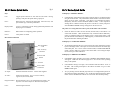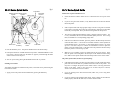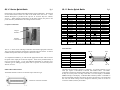
1
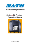
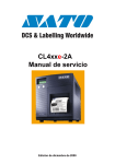
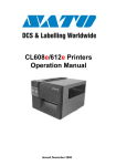
CL408e, CL412e
CL608e, CL612e
(HQ)
(Japan)
(Singapore)
(Malaysia)
(Thailand)
(China)
(USA)
(Belgium)
(Germany)
(Poland)
(UK)
(Holland)
Factory :
(Malaysia)
(Malaysia)
SATO International Pte. Ltd.
SATO Corporation
SATO Asia Pacific Pte. Ltd.
SATO Auto-ID Malaysia Sdn. Bhd.
SATO Auto-ID (Thailand) Co., Ltd
SATO Shanghai Co., Ltd
SATO America, Inc.
SATO Europe NV
SATO Deutchland GmbH
ATO Polska SP Z O.O.
SATO UK Ltd
SATO Rotterdam Logistics Center
The New Sato ‘Enhanced’ Series
SATO Malaysia Electronics Manufacturing Sdn.
Bhd.
SATO Labelling Malaysia Electronics Sdn.Bhd.
Quick Guide
SATO Asia Pacific Pte. Ltd.
438A Alexandra Road
#05-01/02 Alexandra Technopark
Singapore 119967
Tel : (65) 6271 5300; Fax : (65) 6273 6011
Sales Hotline : (65) 6276 2722; Service Hotline : (65) 6273 6455
Email : [email protected]
Website : www.satoworldwide.com
© Copyright 2003
SATO Asia Pacific Pte. Ltd.
Warning : This equipment complies with the requirements in Part 15 of
FCC rules for a Class A computing device. Operation of this
equipment in a residential area may cause unacceptable interference to
radio and TV reception requiring the operator to take whatever steps
necessary to correct the interference.
All rights reserved. No part of this document may be reproduced or
issued to third parties in any form whatsoever without the express
permission of SATO Asia Pacific Pte. Ltd. The materials in this
document are provided for general information and are subject to
change without notice. SATO Asia Pacific Pte. Ltd. assumes no
responsibilities for any errors that may appear.
CL ‘e’ Series Quick Guide
Pg 16
CL ‘e’ Series Quick Guide
Pg 1
Label Rewinder
Table of Contents
The Label Rewinder is an external mechanism that allows labels to be rewound on a
roll as they are being printed. The maximum roll capacity is 10”.
What You Get ……………………………………………………………….… 2
Controls & Indicators …………………………………………………………
Operator Panel ……………………………………..……………….….
LED Indicators …………………………………………………………
Adjustments ……………………………………………………………
Keys ……………………………………………………………………
Rear Panel Connections ………………………………………………..
3
3
3
3
4
4
Initial Setup …………………………………………………………………….
Connecting the Printer …………………………………………………
Printing a Test Label …………………………………………………..
Configuring the Printer ………………………………………………...
Computer Connections…………………………………………………
IEEE 1284 Parallel Interface …………………………………………..
Serial Interface …………………………………………………………
5
5
6
7
8
8
8
CL ‘e’ Series Windows Drivers………………………………………………... 10
Troubleshooting the Printer. …………………………………………………. 10
CL ‘e’ Specifications …………………………………………………………… 14
Media Supplies …………………………………………………………………. 15
Options ………………………………………………………………………….. 15
This Quick Guide was prepared to get you up and running quickly. It will enable you
to get your new SATO CL ‘e’ Series installed and printing with a minimum of effort.
However, it is recommended that you familiarise yourself with the contents of the
Printer’s Operator & Technical Reference Manual for detailed descriptions so you
will be able to properly use the printer to its full potential.
CL ‘e’ Series Quick Guide
Pg 2
CL ‘e’ Series Quick Guide
Pg 15
What You Get
Media & Supplies
The CL ‘e’ Series Thermal Transfer printer comes packed in a protective carton.
Included in the carton are the following items :
The Printer comes from the factory set up to operate with high-quality TechnoTherm
thermal transfer media and ribbons. A sample roll of wax ribbon, ST111 (76.2mm x
15M) is shipped with the printer.
•
CL ‘enhanced’ Series Printer
•
Quick Guide
•
Driver / Manual CD ROM
•
Head Cleaning Sheet
•
Sample Ribbons
•
Ribbon Take-Up Core (Not for Export out of Singapore)
•
Power Cable
•
Test Printout Labels
Other media and supplies may or may not give acceptable results in the printing. It is
likely that you will have to experiment with the heat and speed settings to obtain
quality printing. Instructions for adjusting the heat and speed for optimum print
quality can be found in the Operator & Technical Reference Manual, Section 3.
Options
Plug-In Interface
The Printer uses Plug-In Interface cards for maximum flexibility. Currently available
interfaces are IEEE1284 Parallel, Serial RS232, Universal Serial Bus (USB) and
10/100BaseT Eternet
Label Dispenser
The Printer Label Dispenser Option is an internal mechanism that provides the ability
to print labels in the ‘demand’ mode. When it is installed, the printer dispenses one
label at a time, peeling the backing from the label. The excess label backing is taken
up on an internal rewind spindle.
PCMCIA Memory Expansion
The Memory Expansion option provides the connectors and interface for a PCMCIA
Memory Cards. Each PCMCIA card slot will accept SRAM memory cards up to
4MB SRAM or Flash Memory Card of up to 16MB.
Calendar Option
The Calendar Option allows the date and time to be maintained in the local printer
where it can be recalled for label printing. The Calendar Option is Y2K compliant
and supports both standard and Julian dating.
After taking the CL ‘e’ Series Printer out from the carton and
removing the protective plastic cover, it is ready for
installation.
CL ‘e’ Series Quick Guide
Pg 14
CL ‘e’ Series Specifications
CL ‘e’ Series Quick Guide
Controls & Indicators
The following is a general list of the CL ‘e’ series specifications. For a complete
listing, please refer to the Operator & Technical Reference, Section 1.
SPECIFICATION
PRINT
Method
Speed (User Selectable)
Processor
Resolution
Maximum Print Length
Maximum Print Width
CL408e
CL412e
CL608e
CL612e
Thermal Transfer or Direct Thermal
2 – 6 ips
4 – 8 ips
50 – 150 mm/s
100 – 200 mm/s
32-Bit RISC, 133MHz
203dpi
305 dpi
203dpi
305 dpi
8 dpmm
12 dpmm
8 dpmm
12 dpmm
49.2”
32.8”
49.2”
32.8”
1249mm
833mm
1249mm
833mm
4.1”
6.0”
6.5”
104mm
152mm
164mm
MEDIA
Width
Minimum Length
Roll OD (Maximum)
Label Sensing
RIBBON
Length
Maximum Width
PRINT-OUTS
Text Fonts
Graphics
Bar Codes
Rotation
PHYSICAL
Dimension
0.87” – 5.1”
1.96” – 7”
22mm – 131mm
50mm – 178mm
0.24” (6mm)
0.78” (20mm)
8.6” (218mm), Wound Face-In
Transmissive See-Thru, Reflective I-Mark,
Continuous Forms
1475 ft (450M)
4.4” (111mm)
LED Indicators
Status :
Dark when Off Line
Green when printer is On Line
Red when an error condition exists
Flashing green when printer is imaging data
LCD Display :
Illuminated when power is applied
1345 ft (410M)
6.75” (172mm)
12 Proportional & Mono-Spaced OCR-A & OCR-B
10 Scaleable Vector Fonts
Sato Hex/Binary, .BMP or .PCX
19 including Four (4) 2-D Bar Codes
Text & Bar Codes can be rotated 90o, 180o & 270o
W10.7” x D16.9” x H12.6”
271mm x 429mm x 321mm
28.7 lbs (13 Kg)
Operator Panel
W13.8” x D16.9” x H11.7”
352mm x 429mm x 298mm
41.9 lbs (19 Kg)
Weight
POWER REQUIREMENTS
110V (± 10%); 220V (± 10%); 50/60Hz (±1%)
Voltage
50W Idle; 130W Operating
50W Idle; 210W Operating
Power Consumption
ENVIRONMENTAL
5 – 40oC; 15 – 85% RH, Non Condensing
Operating
-20 – 40oC; Max 90% RH, Non Condensing
Storage
Adjustments (controls behind front panel)
Print :
Adjusts print darkness
Offset:
Adjusts amount of back/forward feed for dispense /
cut / tear-off position (+/- 3.75mm)
Pitch :
Adjusts home position of the label +/- 3.75mm. Affects stop
position of label, print position and dispense / cut position.
DSW2-3 :
Sets printer configuration
Pg 3
CL ‘e’ Series Quick Guide
Pg 4
Keys
CL ‘e’ Series Quick Guide
Pg 13
LCD displays “FRAMING ERROR”
Line :
Toggles printer between On Line and Off Line mode. During
printing it will pause the printer during a print job
Feed :
When Off Line, will feed one blank label. When On Line, will
print another copy of the last printed label
Display Panel:
2-Line x 16 character LCD for setting operational parameters and
displaying error conditions
DSW2-3 :
DIP switches for configuring printer operation
Power :
Turns printer On & Off
•
Communication format between the printer and host must be synchronised when
using the serial interface. The printer RS232 Serial Interface card comes from the
factory set for no parity, 8 data bits, 1 stop bit (N,8,1) at 9600 bps and using a
Ready/Busy data flow control handshake (DSW1-8=OFF). If the computer is
sending data in a different format, the printer is not able to correctly interpret it
and a FRAMING ERROR message will appear on the LCD screen.
The printer is receiving data and seems to print, but the labels come out blank
•
Rear Panel Connections
Check the ribbon to make sure the ink-side (the dull side) of the ribbon is in
contact with the label. Other manufacturers may wind their ribbons differently.
If they are loaded according to the diagram on Pg 6 of this Quick Guide, it will
place the ink-side of the ribbon up. If this happens, you should clean the ink from
the print head before reloading the ribbon.
LCD displays a “PAPER END ERROR”
Plug-In Interface
Card
•
EXT Accessory
Connector
Power On/Off
Switch
LCD displays a “RIBBON END ERROR”
•
If the Ribbon Supply Spindle is not turning, a RIBBON END ERROR message
will appear. Make sure the ribbon supply core is not oversize and is spinning
freely on the spindle.
•
If the Darkness setting is too high, it can sometimes make the ribbon “stick” to
the label. The resulting interruption in the ribbon movement can give a false
RIBBON END signal.
•
Are you printing on direct thermal paper but have not configured the printer for
direct thermal printing with DSW2-1=On? In the direct thermal mode, the ribbon
motion sensor is disabled since ribbons are not used for direct thermal printing.
AC Fuse
Power Cable
Connector
AC Input :
200-240V 50/60 Hz connector. Use the cable supplied
AC Fuse :
Input power protection. Type 3.15A (for CL4xxe);
Type 6.3A (for CL6xxe)/250V
Plug-In Interface:
Plug-In Interface Card. Type specified at time of order. See
Operator & Technical Reference Manual for descriptions
EXT :
External signal connector
Are the labels pushed all the way to the inside of the printer and held in position
by the Label Edge Guide? The Paper Out switch is located near the inside edge
of the label path. If it is not in contact with the media, a PAPER END ERROR
results. Check to make sure a notch or hole in the label is not causing the Paper
Out switch to give a false indication.
CL ‘e’ Series Quick Guide
Pg 12
CL ‘e’ Series Quick Guide
Poor quality printing
Initial Set-Up
•
Connecting the Printer
•
•
•
If the print has sections missing, visually inspect the print head to make sure it is
clean and has no physical damage. If foreign matter is observed, clean the head
using a cotton swab and the Thermal Print Head and Platen Cleaner from the
SATO cleaning kit.
If the print is too light, increase the heat setting using either software or the LCD
panel. If the print is too dark and the bars in a bar code are fuzzy and run
together, lower the heat setting. Fine adjustments can be made by adjusting the
PRINT potentiometer on the front panel.
If the print is too light, try varying the print speed using either the LCD panel or
software commands.
Is your ribbon/label combination compatible? Low quality paper labels may have
a surface that is too rough for resin based ribbons to adhere. Wax based may not
be able to adhere well to some synthetic label material.
LDC displays “SENSOR ERROR”
•
•
Check to make sure the sensing method selected matches the media loaded. The
printer comes from the factory set for detecting a label gap (DSW2-2=OFF) and
there must be a gap of at least 1/8” between labels. If Eye-Mark (a black line
across the underside of the label) labels are used, DSW2-2 must be On to enable
the reflective sensor.
If continuous media is being used without any type of registration, the sensor
must be turned off (DSW3-3=ON).
Otherwise, the printer will feed
approximately 20” of paper and then give a “SENSOR ERROR” message.
Pg 5
1. Locate a suitable spot for the printer. It should be within 6’ of the host if using
IEEE1284 Parallel interface or within 3.5’ if using an RS232 interface. For other
types of Plug-In interface cards, see the Operator & Technical Reference Manual.
Make sure there is adequate room above and to the right of the printer for the label
access door to swing open.
2. Plug the AC cable provided into the back of the printer and connect to a suitable
VAC outlet.
3. Open the print head and load the ribbon using the ribbon routing guide located on
the inside of the top cover. Be sure to position the ribbon roll correctly on the
Ribbon Supply Spindle and place the spare take-up core so that it will take up
when in a counter clockwise direction.
4. Place the label roll on the Label Supply Spindle and push the green Label Roll
Retainer on the spindle until it pushes the label roll all the way to the inside of the
printer. The labels should come off the bottom of the roll (labels wound face-in on
the roll).
5. Route the labels as indicated by the label routing diagram on the inside of the top
cover. The labels should go under the plastic guide, through the Label Sensor
Assembly, under the print head and out the front of the printer. Position the Label
Edge Guide towards the inside of the printer until it barely contacts the ouside
edge of the labels.
6. Close the Print Head Latch and then the side access door last.
•
If the label gap or eye-mark registration bar does not extend across the width of
the label, you may have to adjust the position of Label Sensor Assembly. See the
Operator & Technical Reference Manual, Section 2 for information on adjusting
the Label Sensor Assembly.
7. Select the proper label sensing method using the front panel DIP switches. The
DIP switch function chart is located on the inside of the front cover. The printer
comes from the factory set for label gap detection (DSW2-2, DSW3-3 both OFF).
Note that the OFF position for the DSW switches is down and the ON position up.
•
Make sure the labels are routed through the Label Sensor, not over the top of it.
8. Apply power by placing the front panel Power switch in the “1” position.
9. The Power and On-Line LEDs should be illuminated and ONLINE should be
displayed on the LCD.
10. Press the LINE key once. The On Line LED should go out and OFFLINE should
be displayed on the LCD.
CL ‘e’ Series Quick Guide
Pg 6
Label Roll
Ribbon Rewind Ribbon Supply
Label Roll
Spindle
Spindle
Retainer
Ribbon Path
CL ‘e’ Series Quick Guide
Pg 11
Printer does not print when data is sent
•
Check the interface cable to make sure it is connected to the correct port on the
PC.
•
If you are using the serial interface, verify that the baud rate of the host matches
that of the printer.
•
Some complex labels with large graphic images can take a long time to transmit
to the printer (especially when using the serial interface) and image in the buffer
before they can be printed. Have you allowed enough time for this process?
•
The On-Line LED will blink while the printer is imaging a label in memory. If it
is a very small label, the On-Line LED will blink quickly one time. If it is a long
label, it will blink for a correspondingly longer time.
•
If the On-Line LED does not blink, place the printer in the Hex Dump mode and
resend the data stream. A list of the received data characters will be printed out
in hexidecimal format. See Section 3, Hex Dump Mode on Page 3-25 of the
Operator & Technical Reference Manual for information on how to place the
printer in the Hex Dump mode. If the data cannot be printed in the Hex Dump
mode, the printer is not receiving any data.
12. If the printer feeds 20” of blank labels and stops with a “SENSOR ERROR” on the
LCD screen, check to make sure the labels are properly routed through the label
sensor and not over the top of it.
•
Make sure your computer program is sending data to the correct printer. More
than one printer can be assigned to the same port in the Windows Printer dialog
box. Make sure the printer listed in the Print Setup window is the correct model.
13. Turn AC power off by placing the POWER switch in the “0” position.
The printer feeds a label, but does not print anything
Head Latch
Sensor
Assembly
Label Edge
Guide
Label Path
11. Press the FEED key once. The printer should feed out one label and stop.
•
Is the label wide enough? The first dot print position is on the outside edge of the
print head and narrow labels are justified towards the inside of the printer. You
may have to configure the printer with an Offset value to correctly position the
image on the label. Refer to the Operator & Technical Reference Manual,
Section 2 for instructions on how to do this.
•
If you are printing in the direct thermal mode, make sure you are using direct
thermal paper
•
If you are printing in the thermal transfer mode, check to make sure the ribbon is
loaded properly with the ink (dull side) in contact with the media.
Printing a Test Label
After labels and ribbon are loaded into the printer, a test label can be printed using the
Front Panel Controls.
1. Apply power to the printer while simultaneously pressing the FEED key.
CL ‘e’ Series Quick Guide
Pg 10
Windows Drivers
CL ‘e’ Series Quick Guide
2. The printer will beep once and display
CONFIGURATION” on the LCD screen.
Pg 7
a
‘TEST
PRINT
MODE,
Windows drivers are provided on the CD-ROM. They let you print labels from
virtually any Windows application program. The driver is loaded like any other
Windows printer driver.
After the driver is installed, you can send data to the Printer just like any other printer
on your system – simply specify the specific model in the Print dialog box of your
Windows application. Printer configuration is managed using the Advanced dialog
box. To print bar codes, you must first define a bar code font using the Barcodes
dialog box. Documentation describing how to load, configure and use the Windows
driver is contained in the CD-ROM under ‘Driver Documentation’.
Windows drivers are very convenient for printing limited numbers of labels or simple
production jobs. However, they can also be very inefficient in the way they transfer
data. For e.g., if you choose a printer resident font, the printer responds very quickly.
However, if you specify a Windows True-Type font, it is transmitted to the printer in
a graphics format that results in large data transfers to the printer, slowing down the
printer response time. It is always best to use a Label Design program that supports
all of the features of the SATO printer being used, thereby increasing the efficiency of
the operation and ensuring optimum response time.
3.
Press the FEED key and the LCD will change the display to ‘TEST PRINT SIZE,
10cm’ to prompt user to select size of label.
4.
Press the LINE key to select the size of the label loaded.
5.
Press the FEED key to start printing test labels. The printer will continue to print
test labels until the FEED key is pressed again, placing the printer in the PAUSE
mode. Pressing the FEED key again will continue the test label printing cycle.
6.
To stop printing test labels, pause the printer by pressing the FEED key and then
turn power Off. Turing power back On will place the printer in the normal OnLine mode where it is waiting for print data.
Configuring the Printer
Troubleshooting the Printer
Printer won’t go On-Line
•
•
Is the Power LED on? Check the power cable and AC Fuse.
There is an error condition. Make sure the Head Latch is closed.
Printer beeps and refuses to print
•
This is usually caused by an incorrect data stream. Try placing the printer in the
Hex Dump mode and printing a copy of the data being sent to the printer.
Examine the incoming data stream for incorrect command usage. Refer to the
Operator & Technical Reference Manual for explanations of proper command
usage.
There are two DIP switches (DSW2 & DSW3) located inside the cover. These
switches can be used to set :
•
•
•
•
•
•
Thermal Transfer of Direct Thermal Mode
Label Sensor Enable / Disable
Head Check Mode
Hex Dump Mode
Single Job or Multi-Job Receive Buffer
Operation Mode
In addition, a third DIP switch is located on the RS232 Serial Adapter card and is used
to set the RS232C transmit/receive parameters. Each switch is an eight section toggle
switch. The ON position is always to the top. To set the switches, first power the unit
Off, then position the DIP switches. Finally, after placing the switches in the desired
positions, power the printer back On. The switch settings are read by the printer
electronics during the power up sequence. They will not become effective until the
power is cycled.
CL ‘e’ Series Quick Guide
Pg 8
Other features can be enabled with different DSW switch combinations. The function
of each DSW switch is listed on a chart on the inside of the front cover. A more
detailed description is provided in the Operator & Technical Reference Manual,
Section 3. When changing configuration via the DSW switches, the power to the
printer must be cycled before the new settings become activated.
Computer Connections
Plug-In
Interface
Interface
Connector
CL ‘e’ Series Quick Guide
PIN
1
2
3
4
5
6
7
8
9
10
11
12
13
14
15
16
17
18
SIGNAL
STROBE
DATA 1
DATA 2
DATA 3
DATA 4
DATA 5
DATA 6
DATA 7
DATA 8
DIRECTION
To Printer
PIN
19
SIGNAL
STROBE Return
DIRECTION
Reference
To Printer
To Printer
To Printer
To Printer
To Printer
To Printer
To Printer
To Printer
To Host
To Host
To Host
To Host
To Host
DATA 1 Return
DATA 2 Return
DATA 3 Return
DATA 4 Return
DATA 5 Return
DATA 6 Return
DATA 7 Return
DATA 8 Return
ACK Return
Busy Return
PE Return
Reference
Reference
Reference
Reference
Reference
Reference
Reference
Reference
Reference
Reference
Reference
From Host
To Host
Frame Ground
20
21
22
23
24
25
26
27
28
29
30
31
32
33
34
35
To Host
36
SELECTIN (1)
ACK
BUSY
PTR ERROR
SELECT
AUTOFD (1)
Not Used
Logic Gnd
FG
+5V
(Z=24K ohm)
Pg 9
INIT
FAULT
Not Used
Not Used
Not Used
From Host
(1)
Signals required for IEEE 1284 mode
The CL ‘e’ Series comes with Plug-In Interface card with the appropriate connector.
The type of Plug-In Interface card desired is specified at the time of order. It must be
installed in the printer before the computer connection is made.
To complete the installation, you will need the appropriate interface cable to connect
the printer to the output port of the host computer. These can be purchased locally or
from your SATO supplier. If you need additional information on interface types,
connector types or cabling pin-outs, please refer to Operator & Technical Reference
Manual, Section 6.
IEEE 1284 Parallel Interface
The Parallel interface connector is a female 36-pin Centronics type.
Centronics Connector On Printer
Serial Interface
Pin No.
1
2
3
4
5
6
7
20
Description
Frame Ground
Transmit Data
Receive Data
Request-To-Send
Clear-To-Send
Data Set Ready
Signal Ground
Data Terminal Ready
Pin 13
Pin 25
Pin 1
Pin 14
The RS232 Serial Interface connector is a DB-25F. To correctly interface to a PC
serial port requires a DB-25P/9P to DB-25F Null Modem Cable. The DSW1
configuration settings for the RS232 data format must match those of the host system.
If they do not, the printer will beep when data is sent and display a FRAMING
ERROR message on the display. If the Baud Rate selected by DSW1-5 and DSW1-6
does not match that of the host, the printer will ignore any data sent. The serial baud
rate and word format settings can be changed on either the printer or the host to
correct the condition, but they must match.