1
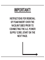
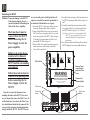
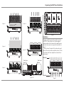
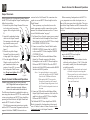
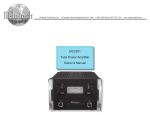
McIntosh Laboratory, Inc.
2 Chambers Street Binghamton, New York
MC275
Tube Power Amplifier
Owner’s Manual
13903-2699 Phone: 607-723-3512
www.mcintoshlabs.com
The lightning flash with arrowhead, within an equilateral
triangle, is intended to alert the user to the presence of
uninsulated “dangerous voltage” within the product’s enclosure that may be of sufficient magnitude to constitute
a risk of electric shock to persons.
WARNING - TO REDUCE RISK
OF FIRE OR ELECTRICAL
SHOCK, DO NOT EXPOSE
THIS EQUIPMENT TO RAIN OR
MOISTURE.
IMPORTANT SAFETY
INSTRUCTIONS!
PLEASE READ THEM BEFORE
OPERATING THIS EQUIPMENT.
1. Read these instructions.
2. Keep these instructions.
3. Heed all warnings.
4. Follow all instructions.
5. Do not use this apparatus near water.
6. Clean only with a dry cloth.
7. Do not block any ventilation openings. Install
in accordance with the manufacturer’s instructions.
8. Do not install near any heat sources such as
radiators, heat registers, stoves, or other apparatus (including amplifiers) that produce heat.
9. Do not defeat the safety purpose of the polarized or grounding-type plug. A polarized plug
has two blades with one wider than the other.
A grounding type plug has two blades and a
2
The exclamation point within an equilateral triangle is
intended to alert the user to the presence of important
operating and maintenance (servicing) instructions in the
literature accompanying the appliance.
NO USER-SERVICEABLE PARTS
INSIDE. REFER SERVICING TO
QUALIFIED PERSONNEL.
third grounding prong. The wide blade or the
third prong are provided for your safety. If
the provided plug does not fit into your outlet,
consult an electrician for replacement of the
obsolete outlet.
10. Protect the power cord from being walked on
or pinched particularly at plugs, convenience
receptacles, and the point where they exit
from the apparatus.
11. Only use attachments/accessories specified by
the manufacturer.
12. Use only with the cart, stand, tripod, bracket,
or table specified by the manufacturer, or sold with the apparatus. When a cart is used, use
caution when moving the cart/
apparatus combination to avoid
injury from tip-over.
13. Unplug this apparatus during lightning storms
or when unused for long periods of time.
14. Refer all servicing to qualified service personnel. Servicing is required when the apparatus
has been damaged in any way, such as power-
To prevent the risk of electric
shock, do not remove cover or
back. No user-serviceable parts
inside.
supply cord or plug is damaged, liquid has
been spilled or objects have fallen into the
apparatus, the apparatus has been exposed to
rain or moisture, does not operate normally, or
has been dropped.
15. Do not expose this equipment to dripping or
splashing and ensure that no objects filled
with liquids, such as vases, are placed on the
equipment.
16. To completely disconnect this equipment from
the a.c. mains, disconnect the power supply
cord plug from the a.c. receptacle.
17. The mains plug of the power supply cord shall
remain readily operable.
18. Do not expose batteries to excessive heat such
as sunshine, fire or the like.
19. Connect mains power supply cord only to a
mains socket outlet with a protective earthing
connection.
IMPORTANT!
INSTRUCTIONS FOR REMOVAL
OF FOAM INSERT OVER THE
VACUUM TUBES PRIOR TO
CONNECTING THE A.C. POWER
SUPPLY CORD, START ON THE
NEXT PAGE.
3
Unpacking the MC275
Caution: To prevent damage to the MC275
Tubes during shipping, there is a
special foam insert surrounding the
Tubes of the Power Amplifier.
The Foam Insert must be
removed from the MC275
before connecting the AC
Power Supply Cord to the
power amplifier.
Failure to do so has the potential of a Fire Hazard,
resulting in damage to the
MC275 and the surrounding
environment.
Follow these instructions for
removal of the packing foam
before connecting the AC
Power Supply Cord to the
MC275.
In order to remove the foam insert surrounding the tubes on the MC275, it is necessary to temporarily remove the Tube Cover. After the foam insert is removed, the Tube Cover
is re-installed and should not be removed. The
cover provides protection from the hazardous
voltages inside the MC275. The MC275 has no
4
user serviceable parts, including the tubes. If
repairs are needed they must be performed by
an authorized McIntosh Service Agency.
1. Orient the MC275 so the Front is facing you and
remove the Warning Sheet. Refer to figure 1.
2. Using a Philips Head #2 screw driver, remove the
Tube Cover Screw securing the Tube Cover to the
chassis on each side of the MC275. Refer to figure
2. Carefully lift up and remove the Tube Cover
from the MC275. Refer to figure 3.
3. Place the Tube Cover and the previously removed
chassis screws in a safe location, as the Tube
Cover will be reinstalled.
4. Carefully lift up and remove the Foam Insert from
the MC275 exposing the Tubes. Refer to figures 4
and 5.
5. Carefully reinstall the previously removed Tube
Cover using a Tube Cover Screw on each side of
the MC275. Refer to figures 6, 7A, 7B and 8.
Note: Only use the chassis screws supplied with the
MC275. If you can not find the chassis screws,
contact the McIntosh Parts Department for
replacements.
6. Save the Foam Insert and Warning Sheet with the
MC275 Shipping Carton for possible future use.
Tube Cover
WARNING
TO AVOID A FIRE HAZARD, THE FOAM INSERT
OVER THE VACUUM TUBES MUST BE REMOVED
PRIOR TO CONNECTING THE A.C. MAINS POWER
SUPPLY CORD AND OPERATING THIS PRODUCT.
REFER TO PAGE 3 IN THE MC275 OWNER’S
MANUAL FOR INSTRUCTIONS.
Tube Cover
Remove Foam
Insert located
under the Tube
Cover
Remove the
Warning Sheet
Tube Cover
Figure 1
Tube Cover
Screw
Tube Cover
Screw
Handcrafted in USA with US
and Imported Parts
Figure 2
Unpacking the MC275 and Ventilation
Figure 3
Foam Insert
Figure 6
Figure 8
Ventilation
Adequate ventilation extends the trouble free life of
the MC275. Always allow air to flow through the
ventilation holes on the bottom of the amplifier and a
means for the warm air to escape at the top. Refer to
figure 9.
Allow at least 19 inches (48.3cm) above the top; 4
inches (10.2cm) for the Rear and Sides; allow 1/2 inch
(1.3cm) below the Power Amplifier so the airflow is
not obstucted.
Figure 4
Figure 7A
Warm Air
Tube Cover
Screw
Tube Cover
Screw
Figure 5
Handcrafted in USA with US
and Imported Parts
Figure 7B
Cool Air
Figure 9
5
Thank You
Customer Service
General Information
Your decision to own this McIntosh MC275 Tube
Power Amplifier ranks you at the very top among
discriminating music listeners. You now have “The
Best.” The McIntosh dedication to “Quality,” is assurance that you will receive many years of musical
enjoyment from this unit.
Please take a short time to read the information in
this manual. We want you to be as familiar as possible with all the features and functions of your new
McIntosh.
If it is determined that your McIntosh product is in
need of repair, you can return it to your Dealer. You
can also return it to the McIntosh Laboratory Service
Department. For assistance on factory repair return
procedure, contact the McIntosh Service Department
at:
McIntosh Laboratory, Inc
2 Chambers Street
Binghamton, New York 13903
Phone: 607-723-3515
Fax: 607-723-1917
1. For additional connection information, refer to the
owner’s manual(s) for any component(s) connected
to the MC275.
2. The MC275 mutes the speaker output for approximately fifteen seconds when first turned on.
3. For the best performance and safety it is important
to always match the impedance of the loudspeaker
to the Power Amplifier connections. Refer to pages
10 thru 13.
Please Take A Moment
Table of Contents
The serial number, purchase date and McIntosh Dealer
name are important to you for possible insurance
claim or future service. The spaces below have been
provided for you to record that information:
Safety Instructions....................................................2-3
Unpacking the MC275 and Ventilation.....................4-5
Thank You and Please Take a Moment........................6
Technical Assistance and Customer Service...............6
Table of Contents.........................................................6
General Information....................................................6
Connector Information................................................7
Introduction..................................................................7
Performance Features..................................................7
Dimensions..................................................................8
Left Side Connections; Indicator and Switch: Right
Side Connection, Fuse Holder and Switch...................9
How to Connect for Stereo Operation....................... 10
Connection Diagram (Separate Sheet).............Mc1A
How to Connect for Monaural Operation..................12
Connection Diagram (Separate Sheet).............Mc1B
Right Side Switch, Left Side Switch and Indicators.. 14
How to Operate.......................................................... 15
Photos.................................................................... 16-17
Specifications............................................................. 18
Packing Instruction.................................................... 19
Serial Number:________________________________
Purchase Date:_ _______________________________
Dealer Name:_ ________________________________
Technical Assistance
If at any time you have questions about your McIntosh
product, contact your McIntosh Dealer who is familiar
with your McIntosh equipment and any other brands
that may be part of your system. If you or your Dealer
wish additional help concerning a suspected problem,
you can receive technical assistance for all McIntosh
products at:
McIntosh Laboratory, Inc.
2 Chambers Street
Binghamton, New York 13903
Phone: 607-723-1545
Fax: 607-724-0549
6
Copyright 2012 © by McIntosh Laboratory, Inc.
Note: The impedance of a Loudspeaker actually varies as the Loudspeaker reproduces different
frequencies. As a result, the nominal impedance
rating of the Loudspeaker (usually measured at
a midrange frequency) might not always agree
with the impedance of the Loudspeaker at low
frequencies where the greatest amount of power
is required. Contact the Loudspeaker Manufacturer for additional information about the actual
impedance of the Loudspeaker before connecting
it to the McIntosh MC275.
4. The Ω is the symbol for the word ohms and refers
to the impedance of the Output Terminals of the
MC275.
5. When discarding the unit, comply with local rules
or regulations. Batteries should never be
thrown away or incinerated but disposed
of in accordance with the local regulations
concerning battery disposal.
6. For additional information on the MC275
and other McIntosh Products please visit
the McIntosh Web Site at www.mcintoshlabs.com.
General Information, Cable Information, Introduction and Performance Features
Connector and Cable Information
XLR Connectors
Below is the Pin configuration for the XLR Balanced
Input, Input/Output Connectors on the MC275. Refer
to the diagram for connection: INPUT
IN/OUT
PIN 1: Shield/Ground
PIN 2: + Output
PIN 3: - Output
PIN 2
PIN 1
PIN 3
PIN 1
PIN 3
PIN 2
Power Control Connector
The MC275 Power Control Input receives an On/Off
signal from +5 to +12 volts. The Power Control Output
will in turn provide a +12 volt Output Signal with a
current up to 20mA. An additional connection is for
controlling the green illumination of the MC275 Small
Signal Tubes when connected to
Power
a compatible McIntosh PreamControl
plifier or A/V Control Center
Meter
Illumination
Power Control Output. The 1/8
inch stereo mini phone plug con- Control Ground
nects to a McIntosh Preamplifier
or A/V Control Center Power Control Output.
Note: When it is desired to switch Off the green illumination of the Small Signal Tubes, and the
MC275 is not connected to a McIntosh McIntosh Preamplifier or A/V Control Center with
meter illumination control, connect a 1/8 inch
Mono mini phone plug to the POWER CONTROL IN jack.
Introduction
Now you can take advantage of traditional McIntosh
standards of excellence in the MC275 Tube Power
Amplifier. The 75 watt power output per channel
will drive any high quality Loudspeaker System. The
MC275 reproduction is sonically transparent and absolutely accurate. The McIntosh Sound is “The Sound of
the Music Itself.”
Performance Features
• Power Output
The MC275 is a Tube Power Amplifier with a capability of 75 watts per channel into 4, 8 or 16 ohm Loudspeakers with less than 0.5% distortion. It may also
be operated in mono at 150 watts into 2, 4, or 8 ohm
Loudspeaker.
• Unity Coupled Circuitry
The MC275 Power Amplifier uses the famous McIntosh Patented Unity Coupled Circuit which provides
low distortion, extended frequency response and cool
operating output tubes.
• Multifilar Wound Output Transformer
The MC275 Output Transformer Windings are part
of the Unity Coupled Circuitry. There are two bifilar
wound primaries, one for the cathodes and one for
the plates. The secondary winding is wound together
with the primary windings. This provides very close
primary to secondary coupling. The result is flat frequency response and wide power bandwidth.
• Balanced and Unbalanced Input
Balanced connections guard against induced noise and
allow long cable runs without compromising sound
quality.
• Sentry Monitor Tube Protection
McIntosh Sentry Monitor Tube Protection Circuits
ensure the MC275 will have a long and trouble free
operating life.
• Gold Plated Connectors and Tube Socket Contacts
Gold Plated Input Jacks and Output Binding Posts
provide trouble free connections. Ceramic tube sockets with gold plated contacts provide protection from
atmospheric contamination. Output Tube Sockets
include Air-Pipe cooling at their bases.
• Custom Gold Plated Jumper Bars
To facilitate the MC275 Power Amplifier Monaural
Parallel Mode of Operation, there are two Custom Designed Gold Plated Jumper Bars included. These bars
provide maximum power transfer and ease of connection to the Output Binding Posts.
• Special Power Supply
A regulated Power Supply, a very large core Power
Transformer and large capacitors ensure stable noise
free operation even though the power line varies.
• LED Tube Illumination
Tri-Color LEDs illuminate the small signal processing tubes of the MC275. They indicate tube warm up,
normal and sentry monitor modes of operation.
• Titanium Chassis with Super Mirror Finish
The famous McIntosh Stainless Steel Chassis with
Super Mirror Finish ensures the pristine beauty of the
MC275 will be retained for many years.
7
Dimensions
Dimensions
The following dimensions can assist in determining
the best location for your MC275.
Left Side View of the MC275
Front View of the MC275
16-1/2"
41.9cm
1-3/4"
4.5cm
7-7/8"
20.0cm
8-1/2"
21.6cm
1-1/4"
3.2cm
Top View of the MC275
1-3/4"
4.5cm
Right Side View of the MC275
13-5/8"
34.6cm
5-9/16"
14.1cm
4-3/8"
11.1cm
12"
30.5cm
Handcrafted in USA with US
and Imported Parts
8
Left Side Connections, Indicator and Switch; Right Side Connection, Fuse Holder and Switch
LEFT OUTPUT
Connections for
a 4, 8 or 16 ohm
Loudspeaker
BALanced INPUTS for audio cables from a Preamplifier or A/V Control Center
audio output
RIGHT OUTPUT
Connections for
a 4, 8 or 16 ohm
Loudspeaker
UNBALancded INPUTS
for audio cables from a
Preamplifier or A/V Control Center audio output
Connect the MC275
power cord to a live AC
outlet. Refer to the nomenclature above this
AC Socket to determine
the correct voltage
AUTO OFF Disables
or Enables the Power
Saving Circuitry1
Handcrafted in USA with US
and Imported Parts
MODE switch selects between
STEREO and MONO Parallel
modes of operation
POWER CONTROL IN receives a turn On/Off
signal from a McIntosh component
POWER CONTROL OUT sends a turn On/Off
signal to the next McIntosh Component
POWER Switch Turns
AC Power On or Off/
Remote (On/Off)
INPUT switch selects
between BALanced
and UNBALanced
Input connections
Fuse holder, refer to the nomenclature
above this fuse holder to determine the
correct the correct fuse size and rating
Standby Power
On Indicator
1
Refer to page 15 for additional information
9
How to Connect for Stereo Operation
Output Terminals
When connecting the Loudspeaker Hookup Cables to
the MC275 Power Amplifier Output Terminals please
follow the steps below:
1. Rotate the top of the Output Terminal Post counterclockwise until an opening
appears. Refer to figures A and
B.
2. Insert the Loudspeaker hookup
cable into the Output Terminal
Opening
Post opening or the cable spade
Figure B
Figure A
lug around the center post of
the Output Terminal. Refer to
figure C.
3. Rotate the top of the Output
Terminal Post clockwise until it
is finger tight. Refer to figure D.
4. Place the supplied McIntosh
Figure C Figure D
Wrench over the top of the Output Terminal and rotate it one
quarter of a turn (90° ) to secure
the Loudspeaker Cable Connection. Do not over tighten. Refer
to figure E.
Figure E
How to Connect for Stereo Operation
Caution: Do not connect the AC Power Cord to the
MC275 Right Side Panel until after the Loudspeaker Connections are made. Failure to
observe this could result in Electric Shock.
The connection instructions below, together with the
MC275 Connection Diagram located on the separate
folded sheet “Mc1A”, is an example of a typical audio
system. Your system may vary from this, however the
actual components would be connected in a similar
manner. For additional information refer to “Connector and Cable Information” on page 7.
10
1. For Remote Power Control, connect a power control
cable from the Audio Preamplifier Power Control
Main Output Jack to the Power Amplifier POWER
CONTROL IN Jack.
2. Connect XLR cables from the Balanced Main
Output connector of the Audio Preamplifier to the
Power Amplifier BALanced INPUTS. Place the
INPUT Switch in the BALANCED Position.
Note: An optional hookup is to use unbalanced
cable and place the INPUT MODE Switch
in the UNBALanced Position.
This McIntosh MC275 Power Amplifier is designed
for Loudspeakers with an impedance of 4 ohms, 8
ohms or 16 ohms. Connect a single Loudspeaker only
to the Output Terminals.
When connecting Loudspeakers to the MC275 it
is very important to use cables of adequate size, so
there is little to no power loss in the cables. The size is
specified in Gauge Numbers or AWG (American Wire
Gauge). The smaller the Gauge number, the larger the
wire size:
Loudspeaker Cable Distance vs Wire Gauge Guide
Loudspeaker
Impedance
25 feet
(7.62 meters)
or less
50 feet
(15.24 meters)
or less
100 feet
(30.48 meters)
or less
4 Ohms
8AWG
12AWG
10AWG
8 Ohms
14AWG
12AWG
10AWG
16 Ohms
16AWG
14AWG
12AWG
3. Prepare the Loudspeaker Hookup Cable for attachment to the MC275 Power Amplifier:
Bare wire cable ends:
Carefully remove sufficient insulation from the
cable ends, refer to figures 1, 2 & 3. If the cable
is stranded, carefully twist the strands together
as tightly as possible.
Figure 1
Figure 2
Figure 3
Notes: 1. If desired, the twisted ends can be tinned
with solder to keep the strands together.
2. The prepared bare wire cable ends may be
inserted into spade lug connectors.
3. Banana plugs are for use in the United
States and Canada only.
Banana Plugs are for use in the United States and
Canada only:
4. Attach the previously prepared
bare wire cable ends into the banana plugs and secure the connections. Refer to figure F.
5. Rotate the top of the Output TermiFigure F
nal Post clockwise until it is finger
tight. Refer to figure G. Then using
the McIntosh Wrench, rotate the
top of the Output Terminal one
quarter of a turn (90° ). Do not
over tighten. Refer to figure E.
6. Referring to figure H, connect
the Loudspeaker hookup cables
with banana plugs into the hole
Figure G
at the top of the MC275 Negative (-) and Positive
Output (+) Terminals. The Positive
Terminals are indenFigure H
tified as 4Ω
(ohms),
Figure
F
8Ω (ohms) or 16Ω
How to Connect for Stereo Operation
(ohms) connection to match the impedance of the
Loudspeaker, being careful to observe the correct
polarities.
If the Loudspeaker’s impedance is in-between the
available connections, use the nearest lower impedance connection. Refer to “General Information” Note
3 on page 6 for additional information.
WARNING: Loudspeaker Terminals are hazardous
live and present a risk of electric shock.
For additional instruction on making
Loudspeaker Connections contact your
McIntosh Dealer or McIntosh Technical Support.
If the Loudspeaker’s impedance is in-between the
available connections, use the nearest lower impedance connection. Refer to “General Information”
Note 3 on page 6 for additional information.
WARNING: Loudspeaker terminals are hazardous live and present a risk of electric
shock. For additional instruction on
making Loudspeaker Connections contact your McIntosh Dealer or McIntosh Technical Support.
9. Connect the MC275 Power Cord to an active AC
outlet.
7. Connect the MC275 Power Cord to an active AC
outlet.
Spade Lug or Wire Connections:
8. Connect the Loudspeaker hookup cables to the
MC275 Negative Output Terminal (-) and Positive Output (+) Terminal indentified as 4Ω (ohms),
8Ω (ohms) or 16Ω (ohms) connection to match
the impedance of the Loudspeaker, being careful
to observe the correct polarities. Insert the spade
lug connector or prepared section of the cable end
into the terminal side access hole, and tighten the
terminal cap until the cable is firmly clamped into
the terminals so the lugs or wire cannot slip out. Do
not over tighten. Refer to figures 4, 5 and figure E.
Note: Refer to “Output Terminals” step 4 on
page 10 for important information.
Figure 4
Figure 5
11
How to Connect for Monaural Operation
Output Terminals
When connecting the Loudspeaker Hookup Cables to
the MC275 Power Amplifier Output Terminals please
follow the steps below:
1. Rotate the top of the Output Terminal Post counterclockwise until an opening
appears. Refer to figures A and
B.
2. Insert the Loudspeaker hookup
cable into the Output Terminal
Opening
Post opening or the cable spade
Figure B
Figure A
lug around the center post of
the Output Terminal. Refer to
figure C.
3. Rotate the top of the Output
Terminal Post clockwise until it
is finger tight. Refer to figure D.
4. Place the supplied McIntosh
Figure C Figure D
Wrench over the top of the Output Terminal and rotate it one
quarter of a turn (90° ) to secure
the Loudspeaker Cable Connection. Do not over tighten. Refer
to figure E.
Figure E
How to Connect for Monaural Operation
Caution: Do not connect the AC Power Cord to the
MC275 Right Side Panel until after the Loudspeaker Connections are made. Failure to
observe this could result in Electric Shock.
The following information is applicable to audio systems using more than one MC275. This would include
a stereo system where one MC275 Power Amplifiers
operating in Mono Mode for the Right Channel and
another MC275 for the Left Channel.
The following connection instructions, together
with the MC275 Connection Diagram located on the
separate folded sheet “Mc1B”, illustrates the con12
nections for the Left Channel. The connections also
applies to a second MC275 Power Amplifier for the
Right Channel.
Your system may vary from this, however the
actual components would be connected in a similar
manner. For additional information refer to “Connector and Cable Information” on page 7.
1. For Remote Power Control, connect a power control
cable from the Audio Preamplifier Power Control
Main Output Jack to the first MC275 Power Amplifier POWER CONTROL IN Jack.
2. Connect a second Power Control Cable from the
POWER CONTROL Output of the first MC275
to the second MC275 Power Amplifier POWER
CONTROL IN Jack.
3. Connect an XLR cable from the Balanced Main
Output Left Channel connector of the Audio
Preamplifier to the first MC275 Power Amplifier
BALanced INPUT R/MONO. Place the INPUT
Switch in the BALANCED position and the MODE
Switch in the MONO position.
Notes: 1. An optional hookup is to use an unbalanced cable and place the INPUT MODE
Switch in the UNBALanced Position.
2. When multiple MC275s are used in a
Stereo System, match up the Preamplifier Channel Output designation to each
MC275 with the Loudspeaker location in
the room.
4. Connect an XLR cable from the Balanced Main
Output Right Channel connector of the Audio Preamplifier to the second MC275 Power Amplifier
BALanced INPUT R/MONO.
The McIntosh MC275 Power Amplifier in MONO
Mode is designed for Loudspeakers with an impedance of 2 ohms, 4 ohms or 8 ohms. Connect a single
Loudspeaker only to the Output Terminals.
When connecting Loudspeakers to the MC275 it
is very important to use cables of adequate size, so
there is little to no power loss in the cables. The size is
specified in Gauge Numbers or AWG (American Wire
Gauge). The smaller the Gauge number, the larger the
wire size:
Loudspeaker Cable Distance vs Wire Gauge Guide
Loudspeaker
Impedance
25 feet
(7.62 meters)
or less
50 feet
(15.24 meters)
or less
100 feet
(30.48 meters)
or less
2 Ohms
12AWG
10AWG
8AWG
4 Ohms
14AWG
12AWG
10AWG
8 Ohms
16AWG
14AWG
12AWG
5. Prepare the Loudspeaker Hookup Cables for attachment to the MC275 Power Amplifier.
Bare wire cable ends:
Carefully remove sufficient insulation from the
cable ends, refer to figures 1, 2 & 3. If the cable
is stranded, carefully twist the strands together
as tightly as possible.
Notes: 1. If desired, the twisted ends can be tinned
with solder to keep the strands together.
2. The prepared bare wire cable ends may be
inserted into spade lug connectors.
3. Banana plugs are for use in the United
States and Canada only.
Figure 1
Figure 2
Figure 3
How to Connect for Monaural Operation
Banana Plugs are for use in the United States and
Canada only:
6. Attach the previously prepared bare wire cable ends
into the banana plugs and secure
the connections. Refer to figure F.
7. For the MC275 MONO Mode of
operation, use the supplied Jumper
Bars to connect the Output of the
Figure F
Left and Right Amplifier Channels
in parallel.
Insert a Jumper Bar into the terminal side access
hole of the LEFT OUTPUT (-) Negative Terminal post and the other end of the Jumper Bar into
the RIGHT OUTPUT (-) Negative Terminal post.
Tighten the terminal caps until the Jumper Bar is
firmly clamped into the terminals so the Jumper
Bar cannot slip out nor touch the chassis. Refer to
Connection Diagram located on the separate folded
sheet “Mc1B”.
8. In a similar manner, connect the other Jumper Bar
between the two (+) Positive 16Ω Output Terminals for connecting a 8Ω (ohm) Loudspeaker (or
between the 8Ω Terminals for a 4Ω (ohm) Loudspeaker, or between the 4Ω Terminals for a 2Ω
(ohm) Loudspeaker). It is important to match the
impedance of the Loudspeaker, being careful to
observe the correct polarities. If the Loudspeaker’s
impedance is in-between the available connections,
use the nearest lower impedance connection. Refer
to “General Information” Note 3
on page 6 for additional information.
9. Rotate the top of the Output
Terminal Posts clockwise until
they are all finger tight. Refer
to figure G. Then using the
Figure G
McIntosh Wrench, rotate the top of the Output
Terminal one quarter of a turn (90° ). Do not over
tighten. Refer to figure E.
10. Referring to figure H, connect the Loudspeaker
hookup cables with
banana plugs into
the hole at the top
Figure
of the MC275
LEFTH
Figure H
OUTPUTFigure
Negative
F
(-) Terminal and the
Positive Output (+) Terminal (which has the previously installed Jumper Bars).
WARNING: Loudspeaker Terminals are hazardous
live and present a risk of electric shock.
For additional instruction on making
Loudspeaker Connections contact your
McIntosh Dealer or McIntosh Technical Support.
11. Connect the MC275 Power Cord to an active AC
outlet.
Spade Lug or Wire Connections:
12. For the MC275 MONO Mode of operation, use the
supplied Jumper Bars for connecting the Output of
the Left and Right Amplifier Channels in parallel.
Insert the Jumper Bar into the terminal side access
hole of the LEFT OUTPUT (-) Negative Terminal post and the other end of the Jumper Bar into
the RIGHT OUTPUT (-) Negative Terminal post.
Tighten the terminal caps until the Jumper Bar is
firmly clamped into the terminals so the Jumper
Bar cannot slip out nor touch the chassis. Refer
to Connection Diagram located on the separate
folded sheet “Mc1B”. Also refer to figures 4, 5 and
figure E.
Figure 4
Figure 5
13. In a similar manner, connect the other Jumper Bar
between the two (+) Positive 16Ω Output Terminals for connecting a 8Ω (ohm) Loudspeaker (or
between the 8Ω Terminals for a 4Ω (ohm) Loudspeaker, or between the 4Ω Terminals for a 2Ω
(ohm) Loudspeaker). It is important to match the
impedance of the Loudspeaker, being careful to
observe the correct polarities. If the Loudspeaker’s
impedance is in-between the available connections,
use the nearest lower impedance connection. Refer
to “General Information” Note 3 on page 6 for additional information.
14. Connect the Loudspeaker hookup cables to the
MC275 LEFT OUTPUT Negative (-) Terminal and
Positive Output (+) Terminal (which has the previously installed Jumper Bars).
WARNING: Loudspeaker terminals are hazardous live and present a risk of electric
shock. For additional instruction on
making Loudspeaker Connections contact your McIntosh Dealer or McIntosh Technical Support.
15. Connect the MC275 Power Cord to an active AC
outlet.
Note: Refer to “Output Terminals” step 4 on
page 12 for important information.
13
Right Side Switch, Left Side Switches and Indicators
AUTO OFF Switches the Power Save
On (ENABLED)or Off (DISABLED)
INPUT Switch selects between
STEREO and MONO Modes
of operation
Small Signal
Vacuum Tube
Handcrafted in USA with US
and Imported Parts
LED Illumination Color:
Amber-Warmup Mode
Green -Normal Operation
Red -Sentry Monitor
INPUT Switch selects
between balanced or
unbalanced input
POWER Switch Turns
AC Power ON, or OFF/
REMOTE
Standby Power
On Indicator
14
How to Operate
How to Operate
Power
With the POWER Switch (located on the Left Side
of the MC275) set to the OFF/REMOTE Position, the MC275 will
turn On or Off when the PreamHandcrafted in USA with US
plifier turns On or Off. For manand Imported PartsFigure 10
ual operation, place the POWER
Switch to the ON Position as desired. Refer
to figure 10. The LED indicator located
above the Power Switch is illuminated when
Figure 11
the MC275 to connected to an active AC
Outlet. Refer to figure 11.
Notes: 1. There must be a power control connection
between the MC275 and the McIntosh Preamplifier in order for the remote power turn-on to
function.
2. To switch the MC275 back On after the Auto
Sense Circuitry has placed the amplifier into
the Standby Mode, it is first necessary to place
the POWER Switch in the OFF/REMOTE position. Then place the POWER Switch in the ON
position. Refer to “Auto Off Switch” below for
additional information.
3. When the MC275 is first switched On, there
is a Warm-Up period of time during which no
sound will be heard; there is also sequential
illumination (amber color) of the Small Signal
Vacuum Tubes. After the Warm-Up period of
time, sound will be heard and the illumination
color of the Small Signal Vacuum Tubes will
change to green.
Auto Off Switch
The MC275 incorporates Power Save Circuitry to
automatically place the MC275 into the power saving
Standby Mode approximately 30 minutes after there
has been an absence of an audio input signal.
When there is a Power Control Connection between the MC275 and a Preamplifier
with Power Save Circuitry, the AUTO OFF
Switch is bypassed (located on the Right
Side Of the MC275). Refer to figure 12.
Figure 12
In the event there is no Power Control
Connection and the Power Save Circuitry is activating inappropriately relative to your specific use of the
MC275, place the AUTO OFF Switch in the DISABLE
position.
Note: If the Power Save Circuitry has switched Power
to the MC275 OFF, place the POWER in the OFF
Position and then in the ON position to reset the
circuitry.
Input Switch
The Input Switch (located on the Left Side of the
MC275) allows you to select either
the BAL (Balanced) or UNBAL (Unbalanced) Input. Refer to figure 13.
Figure 13
Mode Switch
The MODE Switch (located on the Left Side of the
MC275) allows selection of either Stereo or Mono
(Parallel) Modes of Operation. Refer to figure 14 and
pages 10 thru 13 for connection
information.
With the MODE Switch placed
Figure 14
in the STEREO position the MC275
is capable of delivering over 75
watts per channel (Left and Right) into a Loudspeaker
with an impedance1 of 4 Ω, 8 Ω or 16 Ω.
When the MODE Switch is placed in the MONO
position, the MC275 operates in a Single Channel
Mono Parallel Mode and is capable of delivering over
150 watts into a Loudspeaker with an impedance1 of
2 Ω, 4 Ω or 8 Ω.
Sentry Monitor
The MC275 Sentry Monitor Tube Protection Circuitry
provides protection to the Power Amplifier in the
event of an impedance mismatch1 between the MC275
and the Loudspeaker(s). It will also activate if there is
a short circuit at the MC275 Output Terminals (or the
Loudspeaker Terminals) or if a MC275 Power Output
Tube should fail. During normal operation the Sentry
Monitor Tube Protection Circuitry has no effect on the
performance of the Power Amplifier.
In the event a problem occurs, the circuitry will
activate to prevent potentially destructive high levels
of current from flowing in the amplifier. The illumination color of the Small Signal Vacuum Tubes of the
affected channel will change from green to red. To
reset the Sentry Monitor Tube Protection Circuitry
first note the position of the POWER Switch. If the
POWER Switch is set to the OFF/REMOTE position,
switch Off the Preamplifier for approximately one
minute and then switch the Preamplifier On. When
the POWER Switch set to the ON position, place the
POWER Switch to the OFF/REMOTE for approximately one minute, then place the POWER Switch to
the ON position.
1
The impedance of a Loudspeaker actually varies as the
Loudspeaker reproduces different frequencies. As a result,
the nominal impedance rating of the Loudspeaker (usually
measured at a midrange frequency) might not always agree
with the impedance of the Loudspeaker at low frequencies
where the greatest amount of power is required. Contact the
Loudspeaker Manufacturer for additional information about
the actual impedance of the Loudspeaker before connecting
it to the McIntosh MC275.
15
16
Photos
17
Specifications
Specifications
Power Output Stereo
Minimum sine wave continuous average power output
per channel, both channels operating is:
75 watts into 4 ohm loads
75 watts into 8 ohm loads
75 watts into 16 ohm loads
Power Output Mono (Parallel)
Minimum sine wave continuous average power output
is:
150 watts into 2 ohm load
150 watts into 4 ohm load
150 watts into 8 ohm load
Output Load Impedance
4, 8 or 16 ohms (Stereo Mode)
2, 4 or 8 ohms (Mono Mode)
Rated Power Band
20Hz to 20,000Hz
Total Harmonic Distortion
0.5% maximum harmonic distortion at any power
level from 250 milliwatts to rated power, 20Hz to
20,000Hz
Frequency Response
+0, -0.5dB from 20Hz to 20,000Hz
+0, -3.0dB from 10Hz to 100,000Hz
Input Sensitivity (for rated output)
1.7 Volts Unbalanced
3.4 Volts Balanced
18
Signal To Noise Ratio (A-Weighted)
105dB below rated output
Intermodulation Distortion
0.5% maximum, if the instantaneous peak power
output does not exceed twice the rated power output
for any combination of frequencies from 20Hz to
20,000Hz.
Wide Band Damping Factor
Greater than 22
Input Impedance
47,000 ohms Unbalanced
20,000 ohms Balanced
Tube Compliment
3 - 12AX7A Input and Phase Inverter
4 - 12AT7 Voltage Amplifier and Driver
4 - KT88/6550 Power Output
Power Requirements
Field AC Voltage conversion of the MC275 is not
possible. The MC275 is factory configured for one of
the following AC Voltages:
100V ~ 50/60Hz at 4.4 Amps
110V ~ 50/60Hz at 3.6 Amps
120V ~ 50/60Hz at 3.6 Amps
220V ~ 50/60Hz at 2.0 Amps
230V ~ 50/60Hz at 1.8 Amps
240V ~ 50/60Hz at 1.8 Amps
Standby: Less than 0.3 watts
Note: Refer to the right side panel of the MC275 for the
correct voltage.
Overall Dimensions
Width is 21-1/2 inches (54.6cm) including Cables
Height is 8-1/2 inches (21.6cm) including feet
Depth is 12 inches (30.5cm)
Weight
67 pounds (30.5 kg) net, 75 pounds (34.1 kg) in shipping carton
Shipping Carton Dimensions
Width is 22 inches (55.9cm)
Height is 14 inches (35.6cm)
Depth is 16-3/4 inches (42.6cm)
Packing Instructions
Packing Instructions
In the event it is necessary to repack the equipment
for shipment, the equipment must be packed exactly
as shown below. It is very important that the four feet
are attached to the bottom of the equipment. This will
ensure the proper equipment location on the bottom
foam pad. Failure to do this will result in shipping
damage.
To protect the tubes during shippment, the Foam
Insert removed from the MC275 needs to be re-inserted. Follow the unpacking instructions on pages 4-5 in
the reverse order.
Use the original shipping carton and interior parts
only if they are all in good serviceable condition. If
a shipping carton or any of the interior part(s) are
needed, please call or write Customer Service Department of McIntosh Laboratory, refer to page 3. Please
see the Part List for the correct part numbers.
Quantity Part Number
1
034529
1
034526
2
034527
1
034528
1
041314
4
4
400131
163073
TUBE COVER
WITH TUBE
FOAM INSERT
INSIDE TO
PROTECT THE
TUBES
WARNING
SHEET
Description
Shipping carton
Foam Pad Top
Foam Pad Bottom
Foam Insert (for protecting the Tubes during shipping)
Warning Sheet
FOAM PAD
TOP
UNIT WITH
(4) FEET ON
BOTTOM
COVER
POLY BAG
FOAM PAD
BOTTOM
10-32 x 1/2 inch screw
Feet
SHIPPING
CARTON
19
McIntosh Laboratory, Inc.
2 Chambers Street
Binghamton, NY 13903
www.mcintoshlabs.com
The continuous improvement of its products is the
policy of McIntosh Laboratory Incorporated who
reserve the right to improve design without notice.
Printed in the U.S.A.
McIntosh Part No. 04132700