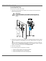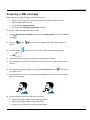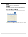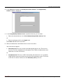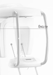
1
CS 9300 User Guide Notice Congratulations on your purchase of the CS 9300. Thank you for your confidence in our products and we will do all in our power to ensure your complete satisfaction. The User Guide for the CS 9300 includes information on the Panoramic and 3D features. We recommend that you thoroughly familiarize yourself with this Guide in order to make the most effective use of your system. The CS 9300 is intended to produce panoramic x-ray imaging at the direction of health care professionals of the dento-maxillo-facial area. In addition, the 3D system includes a dental volumetric reconstruction mode which is intended to produce three-dimensional x-ray images of the dento-maxillo-facial and ENT regions. WARNING: We recommend that you consult the “Safety, Regulatory and the Technical Specification User Guide” before using the CS 9300. The information contained in this Guide may be subject to modification without notice, justification or notification to the persons concerned. No part of this Guide may be reproduced without the express permission of Carestream Health, Inc. The US Federal law restricts this device to sale by or on the order of a physician. This document is originally written in English. Manual Name: CS 9300 User Guide Part Number: SM748 Revision Number: 01 Print Date: 2011-03 The CS 9300, complies with Directive 93/42/CEE relating to medical equipment. 0086 Manufacturer Care stream Hea lth, Inc. 150 Verona Street Roche ster NY 14 608 Authorized Representative in the European Community EC REP TROPHY 4, Rue F. Pelloutier, Croissy-Beaubourg 77435 Marne la Vallée Cedex 2, France Contents 1—About This Guide Conventions in this Guide. . . . . . . . . . . . . . . . . . . . . . . . . . . . . . . . . . . . . . . . . . . . . . . . . . . . . . . . . . . . . . . . . . . . . 1–1 2—CS 9300 GENERAL OVERVIEW Mobile Components . . . . . . . . . . . . . . . . . . . . . . . . . . . . . . . . . . . . . . . . . . . . . . . . . . . . . . . . . . . . . . . . . . . . . . 2–2 General Functional Components . . . . . . . . . . . . . . . . . . . . . . . . . . . . . . . . . . . . . . . . . . . . . . . . . . . . . . . . . . . . 2–3 Digital Sensor Location. . . . . . . . . . . . . . . . . . . . . . . . . . . . . . . . . . . . . . . . . . . . . . . . . . . . . . . . . . . . . . . . . . . . 2–4 Laser Locations . . . . . . . . . . . . . . . . . . . . . . . . . . . . . . . . . . . . . . . . . . . . . . . . . . . . . . . . . . . . . . . . . . . . . . . . . . 2–5 Control Panel . . . . . . . . . . . . . . . . . . . . . . . . . . . . . . . . . . . . . . . . . . . . . . . . . . . . . . . . . . . . . . . . . . . . . . . . . . . . . . . 2–6 X-Ray Remote Control Overview . . . . . . . . . . . . . . . . . . . . . . . . . . . . . . . . . . . . . . . . . . . . . . . . . . . . . . . . . . . . . . . 2–7 Positioning Accessories and Replacement Parts . . . . . . . . . . . . . . . . . . . . . . . . . . . . . . . . . . . . . . . . . . . . . . . . . . 2–8 Panoramic Positioning Accessories . . . . . . . . . . . . . . . . . . . . . . . . . . . . . . . . . . . . . . . . . . . . . . . . . . . . . . . . . 2–8 3D Positioning Accessories . . . . . . . . . . . . . . . . . . . . . . . . . . . . . . . . . . . . . . . . . . . . . . . . . . . . . . . . . . . . . . . . 2–9 Patient Positioning Indicators. . . . . . . . . . . . . . . . . . . . . . . . . . . . . . . . . . . . . . . . . . . . . . . . . . . . . . . . . . . . . . 2–10 3—IMAGING SOFTWARE OVERVIEW Computer System Requirements . . . . . . . . . . . . . . . . . . . . . . . . . . . . . . . . . . . . . . . . . . . . . . . . . . . . . . . . . . . . . . . 3–1 General Software Overview . . . . . . . . . . . . . . . . . . . . . . . . . . . . . . . . . . . . . . . . . . . . . . . . . . . . . . . . . . . . . . . . . . . 3–1 Imaging Software . . . . . . . . . . . . . . . . . . . . . . . . . . . . . . . . . . . . . . . . . . . . . . . . . . . . . . . . . . . . . . . . . . . . . . . . 3–1 Acquisition Interface . . . . . . . . . . . . . . . . . . . . . . . . . . . . . . . . . . . . . . . . . . . . . . . . . . . . . . . . . . . . . . . . . . . . . . 3–1 Acquisition Interface . . . . . . . . . . . . . . . . . . . . . . . . . . . . . . . . . . . . . . . . . . . . . . . . . . . . . . . . . . . . . . . . . . . . . . . . . 3–2 Panoramic Acquisition Overview . . . . . . . . . . . . . . . . . . . . . . . . . . . . . . . . . . . . . . . . . . . . . . . . . . . . . . . . . . . . 3–2 Program Pane . . . . . . . . . . . . . . . . . . . . . . . . . . . . . . . . . . . . . . . . . . . . . . . . . . . . . . . . . . . . . . . . . . . . . . . . 3–4 Patient Pane . . . . . . . . . . . . . . . . . . . . . . . . . . . . . . . . . . . . . . . . . . . . . . . . . . . . . . . . . . . . . . . . . . . . . . . . . 3–5 Parameter Pane. . . . . . . . . . . . . . . . . . . . . . . . . . . . . . . . . . . . . . . . . . . . . . . . . . . . . . . . . . . . . . . . . . . . . . . 3–6 “Premium” 3D Acquisition Overview . . . . . . . . . . . . . . . . . . . . . . . . . . . . . . . . . . . . . . . . . . . . . . . . . . . . . . . . . 3–7 3D Program Pane . . . . . . . . . . . . . . . . . . . . . . . . . . . . . . . . . . . . . . . . . . . . . . . . . . . . . . . . . . . . . . . . . . . . . 3–9 Patient Pane . . . . . . . . . . . . . . . . . . . . . . . . . . . . . . . . . . . . . . . . . . . . . . . . . . . . . . . . . . . . . . . . . . . . . . . . 3–13 Parameter Pane. . . . . . . . . . . . . . . . . . . . . . . . . . . . . . . . . . . . . . . . . . . . . . . . . . . . . . . . . . . . . . . . . . . . . . 3–14 “Select” 3D Acquisition Overview . . . . . . . . . . . . . . . . . . . . . . . . . . . . . . . . . . . . . . . . . . . . . . . . . . . . . . . . . . 3–15 3D Program Pane . . . . . . . . . . . . . . . . . . . . . . . . . . . . . . . . . . . . . . . . . . . . . . . . . . . . . . . . . . . . . . . . . . . . 3–17 Patient Pane . . . . . . . . . . . . . . . . . . . . . . . . . . . . . . . . . . . . . . . . . . . . . . . . . . . . . . . . . . . . . . . . . . . . . . . . 3–19 Parameter Pane. . . . . . . . . . . . . . . . . . . . . . . . . . . . . . . . . . . . . . . . . . . . . . . . . . . . . . . . . . . . . . . . . . . . . . 3–20 4—GETTING STARTED Switching on the Unit . . . . . . . . . . . . . . . . . . . . . . . . . . . . . . . . . . . . . . . . . . . . . . . . . . . . . . . . . . . . . . . . . . . . . . . . Starting the Imaging Software . . . . . . . . . . . . . . . . . . . . . . . . . . . . . . . . . . . . . . . . . . . . . . . . . . . . . . . . . . . . . . . . . Starting the KODAK Dental Imaging Software. . . . . . . . . . . . . . . . . . . . . . . . . . . . . . . . . . . . . . . . . . . . . . . . . Creating a Patient Record . . . . . . . . . . . . . . . . . . . . . . . . . . . . . . . . . . . . . . . . . . . . . . . . . . . . . . . . . . . . . . Accessing the Acquisition Interface . . . . . . . . . . . . . . . . . . . . . . . . . . . . . . . . . . . . . . . . . . . . . . . . . . . . . . Starting the CS Imaging Software. . . . . . . . . . . . . . . . . . . . . . . . . . . . . . . . . . . . . . . . . . . . . . . . . . . . . . . . . . . Creating a Patient Card . . . . . . . . . . . . . . . . . . . . . . . . . . . . . . . . . . . . . . . . . . . . . . . . . . . . . . . . . . . . . . . . Accessing the Acquisition Interface . . . . . . . . . . . . . . . . . . . . . . . . . . . . . . . . . . . . . . . . . . . . . . . . . . . . . . 4–1 4–2 4–2 4–2 4–3 4–4 4–4 4–5 5—ACQUIRING PANORAMIC IMAGES CS 9300 System User Guide (SM748)_Ed 01 iii Contents Acquiring a Panoramic, TMJ x2 or Sinus Image . . . . . . . . . . . . . . . . . . . . . . . . . . . . . . . . . . . . . . . . . . . . . . . . . . . 5–1 Preparing the Unit and Setting the Acquisition Parameters . . . . . . . . . . . . . . . . . . . . . . . . . . . . . . . . . . . . . . 5–1 Preparing and Positioning the Patient . . . . . . . . . . . . . . . . . . . . . . . . . . . . . . . . . . . . . . . . . . . . . . . . . . . . . . . . 5–3 Launching the X-ray . . . . . . . . . . . . . . . . . . . . . . . . . . . . . . . . . . . . . . . . . . . . . . . . . . . . . . . . . . . . . . . . . . . . . . . 5–6 Acquiring a TMJ x4 Image . . . . . . . . . . . . . . . . . . . . . . . . . . . . . . . . . . . . . . . . . . . . . . . . . . . . . . . . . . . . . . . . . . . . . 5–7 X-Ray Dose Emission Information . . . . . . . . . . . . . . . . . . . . . . . . . . . . . . . . . . . . . . . . . . . . . . . . . . . . . . . . . . . . . . . 5–8 6—ACQUIRING 3D IMAGES Acquiring 3D Images . . . . . . . . . . . . . . . . . . . . . . . . . . . . . . . . . . . . . . . . . . . . . . . . . . . . . . . . . . . . . . . . . . . . . . . . . 6–1 Preparing the Unit and Setting the Acquisition Parameters . . . . . . . . . . . . . . . . . . . . . . . . . . . . . . . . . . . . . . 6–1 Preparing and Positioning the Patient . . . . . . . . . . . . . . . . . . . . . . . . . . . . . . . . . . . . . . . . . . . . . . . . . . . . . . . . 6–3 Launching the x-ray . . . . . . . . . . . . . . . . . . . . . . . . . . . . . . . . . . . . . . . . . . . . . . . . . . . . . . . . . . . . . . . . . . . . . . . 6–6 X-Ray Dose Emission Information . . . . . . . . . . . . . . . . . . . . . . . . . . . . . . . . . . . . . . . . . . . . . . . . . . . . . . . . . . . . . . . 6–7 7—MAINTENANCE Cleaning Schedule . . . . . . . . . . . . . . . . . . . . . . . . . . . . . . . . . . . . . . . . . . . . . . . . . . . . . . . . . . . . . . . . . . . . . . . . . . . 7–1 Daily . . . . . . . . . . . . . . . . . . . . . . . . . . . . . . . . . . . . . . . . . . . . . . . . . . . . . . . . . . . . . . . . . . . . . . . . . . . . . . . . . . . . . . . 7–1 Monthly . . . . . . . . . . . . . . . . . . . . . . . . . . . . . . . . . . . . . . . . . . . . . . . . . . . . . . . . . . . . . . . . . . . . . . . . . . . . . . . . . . . . 7–2 Annually . . . . . . . . . . . . . . . . . . . . . . . . . . . . . . . . . . . . . . . . . . . . . . . . . . . . . . . . . . . . . . . . . . . . . . . . . . . . . . . . . . . . 7–2 Controlling the Image Quality . . . . . . . . . . . . . . . . . . . . . . . . . . . . . . . . . . . . . . . . . . . . . . . . . . . . . . . . . . . . . . . . . . 7–2 8—TROUBLESHOOTING Quick Troubleshooting . . . . . . . . . . . . . . . . . . . . . . . . . . . . . . . . . . . . . . . . . . . . . . . . . . . . . . . . . . . . . . . . . . . . . . . . 8–1 iv Chapter 1 About This Guide Conventions in this Guide The following special messages emphasize information or indicate potential risk to personnel or equipment: WARNING Warns you to avoid injury to yourself or others by following the safety instructions precisely. CAUTION Alerts you to a condition that might cause serious damage. IMPORTANT Alerts you to a condition that might cause problems. NOTE Emphasizes important information. TIP Provides extra information and hints. CS 9300 System User Guide (SM748)_Ed 01 1–1 Conventions in this Guide 1–2 About This Guide Chapter 2 CS 9300 GENERAL OVERVIEW The CS 9300 is composed of the following functional components: The unit head that contains all the electronic control The rotative arm The fixed arm with a control panel The panoramic and 3D digital sensor The x-ray source assembly The x-ray remote control The chin rest base The panoramic chin rest and bite block The 3D chin rest and bite block The 3D head support The temple supports The hand grips The acquisition software (see “Imaging Software Overview”) The following figures illustrate the general overview of the CS 9300. CS 9300 System User Guide (SM748)_Ed 01 2–1 Mobile Components Figure 2-1 illustrates the up and down movement of the CS 9300 mobile components and the 180° rotation of the rotative arm. Figure 2–1 2–2 CS 9300 GENERAL OVERVIEW CS 9300 Mobile Components General Functional Components Figure 2-2 illustrates the general functional components of the CS 9300. Figure 2–2 CS 9300 Functional Components 5b 5 10 1 9 2 7 6 8 11 5a 5 3 4 1 ON/OFF button 6 Temple supports 2 Unit fixed arm 7 Sensor 3 Control panel 8 X-Ray source assembly 4 Hand Grips 9 Unit rotative arm 5 Chin rest base 10 X-Ray remote control 5a Panoramic chin rest 11 Computer hosting the imaging and the acquisition software 5b 3D head rest CS 9300 System User Guide (SM748)_Ed 01 2–3 Digital Sensor Location Figure 2-3 illustrates the location of the digital sensor of the CS 9300. Figure 2–3 2–4 CS 9300 GENERAL OVERVIEW Digital Sensor Location Laser Locations Figure 2-4 illustrates the location of the lasers of the CS 9300. Figure 2–4 CS 9300 Unit Laser Beam Positions A 3 2 4 1 2 3 B 4 A B 1 1 2 1 3D central positioning (center of rotation) laser beam 2 Mid-sagittal positioning laser beam 3 Horizontal positioning laser beam (panoramic only) 4 3D Field of View (FoV) positioning laser beam CS 9300 System User Guide (SM748)_Ed 01 2–5 Control Panel Control Panel The control panel is an alphanumeric, digital soft touch console. It allows the operator to control certain unit functions. It also displays the operating parameters and error messages. Figure 2–5 Unit Control Panel 8 kV mA 1 2 3 S mem 9 2–6 10 11 4 5 6 1 Height Adjustment button: Adjusts the height of the unit to the height of the patient. 2 3D Head Adjustment button: Adjusts the patient head to the x-ray beams. 3 3D Adjustment buttons (active in Technical Mode only): Adjusts the system rotative arm movements. 4 Laser Beam button: Activates the beams to correctly position the patient. 5 Target Position button: Positions the unit rotative arm at the selected position. 6 Reset button: Resets the unit arm to the initial position to enable the patient to enter and exit the unit. 7 3D Memorization button (active in Technical Mode only): Memorizes the 3D current positioning parameter settings that override the default parameters. 8 Display Screen: Displays the current acquisition parameters and the error messages. 9 Ready Indicator LED: Green, indicates the unit is ready for acquisition. 10 X-Ray Emission LED: Yellow, indicates the x-rays are being emitted. 11 System Status LED: Red, indicates the error alerts. CS 9300 GENERAL OVERVIEW 7 X-Ray Remote Control Overview X-Ray Remote Control Overview The x- ray remote control enables you to launch a radiological image acquisition via the exposure button from outside the x-ray room. You must press and hold the exposure button until the end of acquisition. Premature release of the exposure button interrupts the acquisition. Figure 2–6 X-Ray Remote Control 1 1 Exposure button: launches image acquisition. CS 9300 System User Guide (SM748)_Ed 01 2–7 Positioning Accessories and Replacement Parts Positioning Accessories and Replacement Parts The following accessories are used when positioning a patient. They are delivered with the CS 9300. Panoramic Positioning Accessories Table 2-1 lists the panoramic positioning accessories. Table 2–1 Panoramic Positioning Accessories and Replacement Parts Accessory Description Panoramic chin rest TMJ x2 Sinus TMJ x4 nose rest Panoramic standard bite block Bite block for edentulous patients Single use sheaths for bite blocks (500 pcs box) 2–8 CS 9300 GENERAL OVERVIEW Positioning Accessories and Replacement Parts 3D Positioning Accessories Table 2-2 lists the 3D positioning accessories. Table 2–2 3D Positioning Accessories and Replacement Parts Accessory Description 3D bite block 3D bite block support 3D head rest Single use hygienic sleeves for 3D bite block (100 pcs box) CS 9300 System User Guide (SM748)_Ed 01 2–9 Positioning Accessories and Replacement Parts Patient Positioning Indicators Table 2-3 lists the patient positioning indicators represented on the chin rest base. Table 2–3 Patient Positioning Indicators Positioning Indicators Description For 3D upper jaw positioning For sinus positioning For 3D lower jaw positioning 2–10 CS 9300 GENERAL OVERVIEW For TMJ x2 and TMJ x4 positioning For panoramic positioning Chapter 3 IMAGING SOFTWARE OVERVIEW Computer System Requirements For the minimum computer system requirements and configuration for the Imaging Software, see the CS 9300 and CS 9300C Safety, Regulatory and Technical Specifications User Guide. IMPORTANT It is MANDATORY to check that the computer system configuration is compatible with the computer system requirements for the CS 9300 software. If necessary you MUST update your computer system configuration. The CS 9300 MUST be connected to the computer via a point-to-point Ethernet link and not via a LAN. General Software Overview The CS 9300 operates with the following software: Imaging Software Acquisition interface Imaging Software The imaging software is a user-friendly working interface that was designed and developed specifically for radiological diagnosis. It is the common imaging platform for all our digital systems. The imaging software has the following features: Patient management Extraoral and intraoral image management 3D image management Acquisition Interface The Acquisition interface is a user-friendly working interface that was designed and developed specifically for the CS 9300. The Acquisition interface has the following features: The Panoramic Acquisition interface The 3D Acquisition interface CS 9300 System User Guide (SM748)_Ed 01 3–1 Acquisition Interface Acquisition Interface Panoramic Acquisition Overview The Panoramic Acquisition interface is the main panoramic interface with the CS 9300 that provides you with imaging acquisition functions. Panoramic Acquisition interface Figure 3–1 1 Information button: About: Identifies the Software and the Firmware versions. 3–2 Reset of the Values: Resets to the manufacturing parameter settings. Memorize settings: Memorizes the user preference settings for each patient type (kV, mA and seconds). Save current mode as default: Sets the current selected program to be available by default each time you access the Acquisition interface. Activate the Phantom mode: Sets the unit parameters to perform an image quality control test. 2 Preview Screen: Displays the acquired image in real time. 3 Selected Parameter Display: Displays the current acquisition parameter settings. 4 System Status Screen: Displays various alert or warning messages originating from the unit. IMAGING SOFTWARE OVERVIEW Acquisition Interface 5 Generator Cooling indicator: Indicates the automatic cooling time (mm:ss) required for the generator to reach 0 for a new acquisition. 6 Stop button: Stops the unit rotative arm movement 7 Ready Indicator LED Green indicates the unit is ready to start acquisition. Black indicates the unit is not ready to start acquisition. 8 X-Ray Emission indicator: Yellow, indicates the x-ray emission status. 9 Exit button: Closes the Acquisition interface. 10 Selector Button: Selects different acquisition setting options. Click Program to select examination type options. Click Patient to select patient type parameters. Click Parameters to select exposure parameter options. CS 9300 System User Guide (SM748)_Ed 01 3–3 Acquisition Interface Program Pane The Program pane enables you to choose different radiological exams. The diagram in the Program pane represents a jaw, with the right side of the diagram corresponding to the right side of the patient. Click on a section of the jaw to select an anatomical zone for radiological exam. The selected segment is highlighted. Figure 3–2 1 2 Program Pane TMJ exam options: Select for a TMJ x2. Select for a TMJ x4 exam and click . Radiological exam options: Click Click Click for a Maxillary Sinus exam. for an anterior exam. for a Panoramic exam. NOTE The above list of exam types are only a sample of exam options of the Program pane. 3–4 IMAGING SOFTWARE OVERVIEW Acquisition Interface Patient Pane The Patient Pane enables you to choose different patient parameters. The selection of the patient parameters influences the quality of the image. The selected parameters must be based on the age and morphology of the patient . Figure 3–3 1 2 3 Patient Pane Patient type parameters: Click if the patient is a child. Click if the patient is small. Click if the patient is medium. Click if the patient is large. Patient dental arch morphology: Click for a square dental arch. Click for a normal shape dental arch. Click for a sharp dental arch. Incisors orientation: Click for a vestibular orientation. Click for an axial orientation. Click for a lingual orientation. CS 9300 System User Guide (SM748)_Ed 01 3–5 Acquisition Interface Parameter Pane The Parameter pane enables you to choose exposure parameters for the radiological image acquisition. If the default parameter setting is not adapted to your patient’s type, you can manually adapt the parameter settings to the patient’s type and save this setting as the default setting. Figure 3–4 1 Parameter Pane Exposure settings: kilovolt milliampere 2 Fine-tuning buttons: Click 3 to fine-tune the kV and click Exposure time (for information only): seconds 3–6 IMAGING SOFTWARE OVERVIEW to fine-tune the mA. Acquisition Interface “Premium” 3D Acquisition Overview The “Premium” 3D Acquisition interface is the optimum 3D interface for the CS 9300 that provides you with the full range of imaging acquisition functions. Figure 3–5 “Premium” 3D Acquisition interface 1 Information button: About: Identifies the Software and the Firmware versions. 2 Reset of the Values: Resets to the manufacturing parameter settings. Memorize settings: Memorizes the user preference settings for each patient type (kV, mA and voxel size). Save current mode as default: Sets the current selected program to be available by default each time you access the Acquisition interface. Activate the Phantom mode: Sets the unit parameters to perform an image quality control test. Preview Screen: Before exposure: Displays an illustration of the selected FoV inside the anatomy. During exposure: Displays the acquired image in real time. 3 Selected Parameter Display: Displays the current acquisition parameter settings. 4 System Status Screen: Displays various alert or warning messages originating from the unit. 5 Generator Cooling indicator: Indicates the automatic cooling time (mm:ss) required for the generator to reach 0 for a new acquisition. CS 9300 System User Guide (SM748)_Ed 01 3–7 Acquisition Interface 6 Stop button: Stops the unit rotative arm movement. 7 Pre-shoot button: Performs a single scout image to validate the proper selection of the region of interest. 8 Ready Indicator LED: Green indicates the unit is ready to start acquisition 9 X-Ray Emission Indicator: Yellow indicates the x-ray emission status. 10 Exit button: Closes the Acquisition interface. 11 Selector button: Selects different acquisition setting options. Click Program to select examination type options 3–8 Black indicates the unit is not ready to start acquisition IMAGING SOFTWARE OVERVIEW Click Patient to select patient type parameters Click Parameters to select exposure parameter options Acquisition Interface 3D Program Pane The 3D Program pane enables you to choose different radiological exams. See below the different radiological exams program pane and their features. Figure 3–6 Head Program Pane Fast Acquisition button: Minimizes the acquisition time to avoid the patient’s movement. Maximum Field Of View (FOV) button: Enables the maximum field of view radiological exam. Figure 3–7 Sinus Program Pane Fast Acquisition button: Minimizes the acquisition time to avoid the patient’s movement. High Quality Acquisition button: Longer acquisition time with more projections for maximum quality image. Maximum Field Of View (FOV) button: Enables the maximum field of view radiological exam. CS 9300 System User Guide (SM748)_Ed 01 3–9 Acquisition Interface Figure 3–8 Ear Program Pane Ear exam options: Right ear: Acquisition of right ear. Left ear: Acquisition of left ear. Right & Left ears: Acquisition of both right and left ears. Image program options: Fast Acquisition button: Minimizes the acquisition time to help avoid patient movement. High Quality Acquisition button: Longer acquisition time with more projections for maximum quality image. Extended temporal bone area: Enables capturing more structures around the temporal bone. Right & Left ear acquisition: Only available with the Right & Left ears program. 3–10 IMAGING SOFTWARE OVERVIEW Acquisition Interface Figure 3–9 Teeth Program Pane Teeth setting options: Teeth buttons: Select a group of teeth to be included in the exam. Upper and lower jaw have the same setting here and will then be designated during the patient positioning. Program options: Fast Acquisition button: Minimizes the acquisition time to help avoid patient movement. High Quality Acquisition button: Longer acquisition time with more projections for maximum quality image. Figure 3–10 Jaw Program Pane Both jaws restricted acquisition: Ideal for jaw exams when the third molars are not required. Single jaw full acquisition: Upper or lower jaw exam only. Both jaws full acquisition: Full upper and lower jaws exam. CS 9300 System User Guide (SM748)_Ed 01 3–11 Acquisition Interface Figure 3–11 TMJ Program Pane TMJ exam options: Right TMJ: Acquisition of right TMJ. Left TMJ: Acquisition of left TMJ. Right & Left TMJs: Acquisition of both right and left TMJs. Program options: Single TMJ acquisition: Available only with Left or Right program option. Both TMJ acquisition: Available only with Right & Left program option. 3–12 IMAGING SOFTWARE OVERVIEW Acquisition Interface Patient Pane The Patient pane enables you to choose different patient parameters. The selection of the patient parameters influences the quality of the image and the correct positioning of small FoVs. The selected parameters must be based on the age and morphology of the patient. Figure 3–12 Patient Pane Patient type parameters: The patient is a child. The patient is small. The patient is medium. The patient is large. CS 9300 System User Guide (SM748)_Ed 01 3–13 Acquisition Interface Parameter Pane The Parameter pane enables you to choose exposure parameters for the radiological image acquisition. If the default parameter setting is not adapted to your patient’s type, you can manually adapt the parameter settings to the patient’s type and save this setting as the user-defined setting. Figure 3–13 Parameter Pane Exposure settings: kV: kilovolts mA: milliamperes Image resolution options: µm (Voxel): micrometer. Most exams can be performed using different voxel sizes. Fine-tuning buttons: Fine-tune the kV, the mA and the µm (voxel). 3–14 IMAGING SOFTWARE OVERVIEW Acquisition Interface “Select” 3D Acquisition Overview The “Select” 3D Acquisition interface is the 3D interface for the CS 9300 that provides you with a selected range of imaging acquisition functions. Figure 3–14 “Select” 3D Acquisition interface 1 Information button: About: Identifies the Software and the Firmware versions. 2 Reset of the Values: Resets to the manufacturing parameter settings. Memorize settings: Memorizes the user preference settings for each patient type (kV, mA and voxel size). Save current mode as default: Sets the current selected program to be available by default each time you access the Acquisition interface. Activate the Phantom mode: Sets the unit parameters to perform an image quality control test. Preview Screen: Before exposure: Displays an illustration of the selected FoV inside the anatomy. During exposure: Displays the acquired image in real time. 3 Selected Parameter Display: Displays the current acquisition parameter settings. 4 System Status Screen: Displays various alert or warning messages originating from the unit. 5 Generator Cooling indicator: Indicates the automatic cooling time (mm:ss) required for the generator to reach 0 for a new acquisition. CS 9300 System User Guide (SM748)_Ed 01 3–15 Acquisition Interface 6 Stop button: Stops the unit rotative arm movement. 7 Pre-shoot button: Performs a single scout image to validate the proper selection of the region of interest. 8 Ready Indicator LED: Green indicates the unit is ready to start acquisition 9 X-Ray Emission Indicator: Yellow indicates the x-ray emission status. 10 Exit button: Closes the Acquisition interface. 11 Selector button: Selects different acquisition setting options. Click Program to select examination type options 3–16 Black indicates the unit is not ready to start acquisition IMAGING SOFTWARE OVERVIEW Click Patient to select patient type parameters Click Parameters to select exposure parameter options Acquisition Interface 3D Program Pane The 3D Program pane enables you to choose different radiological exams. See below the different radiological exams program pane and their features. Figure 3–15 Teeth Program Pane Teeth setting options: Teeth buttons: Select a group of teeth to be included in the exam. Upper and lower jaw have the same setting here and will then be designated during the patient positioning. Program options: Fast Acquisition button: Minimizes the acquisition time to help avoid patient movement. High Quality Acquisition button: Longer acquisition time with more projections for maximum quality image. CS 9300 System User Guide (SM748)_Ed 01 3–17 Acquisition Interface Figure 3–16 Jaw Program Pane Both jaws restricted acquisition: Ideal for jaw exams when the third molars are not required. Single jaw full acquisition: Upper or lower jaw exam only. Figure 3–17 TMJ Program Pane TMJ exam options: Right TMJ: Acquisition of right TMJ. Left TMJ: Acquisition of left TMJ. 3–18 IMAGING SOFTWARE OVERVIEW Acquisition Interface Patient Pane The Patient pane enables you to choose different patient parameters. The selection of the patient parameters influences the quality of the image and the correct positioning of small FoVs. The selected parameters must be based on the age and morphology of the patient. Figure 3–18 Patient Pane Patient type parameters: The patient is a child. The patient is small. The patient is medium. The patient is large. CS 9300 System User Guide (SM748)_Ed 01 3–19 Acquisition Interface Parameter Pane The Parameter pane enables you to choose exposure parameters for the radiological image acquisition. If the default parameter setting is not adapted to your patient’s type, you can manually adapt the parameter settings to the patient’s type and save this setting as the user-defined setting. Figure 3–19 Parameter Pane Exposure settings: kV: kilovolts mA: milliamperes Image resolution options: µm (Voxel): micrometer. Most exams can be performed using different voxel sizes. Fine-tuning buttons: Fine-tune the kV, the mA and the µm (voxel). 3–20 IMAGING SOFTWARE OVERVIEW Chapter 4 GETTING STARTED Switching on the Unit Before switching on the unit, check that: The installation of the unit is complete. The computer is switched on. IMPORTANT You must switch on the computer and wait for it to be ready for the connection before switching on the unit. To switch on the unit, follow these steps: 1 On the unit column, press the ON button. 2 Switch on the unit and wait for a minute for the connection between the unit and the computer to be established. In the status bar, must become . 3 If you start the imaging software before the connection is established an error message is displayed. Click OK, close the imaging software and wait for the connection to be established. 4 You can now proceed to start the imaging software. IMPORTANT To increase the operating life of the x-ray tube, if the unit has not been used for a month, you must follow the following procedures before use. 1 In the Panoramic Acquisition interface, select the Parameter pane. 2 Select the following series of parameter settings: 70 kV - 6.3 mA 80 kV - 10 mA 85 kV - 10 mA CS 9300 Imaging System User Guide (SM748)_Ed 01 4–1 Starting the Imaging Software 3 Leave the x-ray room and close the door. For each parameter setting, from the x-ray remote control, press and hold the button to launch the x-ray The unit is now ready to be used for acquisition. Starting the Imaging Software Depending on your particular configuration you may have either Kodak Dental Imaging Software or CS Imaging Software installed. For KODAK Dental Imaging Software see “Starting the KODAK Dental Imaging Software”. For CS Imaging Software see “Starting the CS Imaging Software”. Starting the KODAK Dental Imaging Software To start the imaging software, follow these steps: 1 On your desktop, double-click . OR From your computer, click Start > All Programs > Kodak > Kodak Dental Imaging Software. A blank Patient Window is displayed. 2 Create or open an existing patient record. Creating a Patient Record To create a patient record, follow these steps: 1 In the Patient Window, from the toolbar, click OR From the menu bar, select Patient > New. 4–2 GETTING STARTED . Starting the Imaging Software 2 Enter the required patient information. The Last name, the First name and the Date of birth fields are required. 3 From the menu bar, select Picture > Insert Picture to add a *.tif or *.bmp picture of the patient to the record. Select the picture from your directory and click Open. 4 Click OK to save. The patient record is automatically assigned a 7-digit number starting with a letter (for example, M0000001). 5 Click 6 Select an image acquisition. to access the Imaging window. Accessing the Acquisition Interface To access the Acquisition interface, follow these steps: 1 In the Imaging window, from the toolbar, click Acquisition window, or, click 2 to access the Panoramic to access the 3D Acquisition window. See the chapter “Acquiring an Image” to launch an acquisition. CS 9300 Imaging System User Guide (SM748)_Ed 01 4–3 Starting the Imaging Software Starting the CS Imaging Software To start the CS Imaging Software, follow these steps: 1 On your desktop, double-click . The Patient Browser tab is displayed. 2 You must now create a patient card. Creating a Patient Card To create a patient card, follow these steps: 1 Click in the Patient Browser tab. The Patient Card window is displayed. 2 Enter the patient information in the Patient Card window. Note: The First Name and Last Name fields are mandatory. All other fields are optional. Shaded fields are filled automatically and are not editable. 3 When you have finished entering data, click OK. The Patient Card window closes, and the patient now appears in the patient list. 4–4 GETTING STARTED Starting the Imaging Software 4 You can now access the acquisition interface. Accessing the Acquisition Interface To access the Acquisition interface, follow these steps: 1 Select and double-click the patient card in the patient list. The Image Viewer tab is displayed. 2 In the Image Viewer tab, click click to access the Panoramic Acquisition interface, or, to access the 3D Acquisition interface. The acquisition interface is displayed. 3 See the chapter “Acquiring an Image” to launch an acquisition. CS 9300 Imaging System User Guide (SM748)_Ed 01 4–5 Starting the Imaging Software 4–6 GETTING STARTED Chapter 5 ACQUIRING PANORAMIC IMAGES Acquiring a Panoramic, TMJ x2 or Sinus Image Before acquiring an image, check that you have: Reset the unit rotative arm to the start position for patient to enter the unit. Selected the patient record. Accessed the Imaging window. Accessed the Panoramic Acquisition interface. Preparing the Unit and Setting the Acquisition Parameters To set the acquisition parameters, follow these steps: 1. In the Panoramic Acquisition interface, click the Program button to access the Program pane. Click on the section of the jaw to select the anatomical zone for the x-ray image, such as panoramic, TMJ x2 or sinus. (Optional) Click and select Save current mode as default if you would like the current selected program to be available by default each time you access the Acquisition interface. 2. Click the Patient button to access the Patient pane. Select the patient: Type Dental arch morphology Incisors orientation 3. If the default parameter setting is not adapted to your patient type, click the Parameter button and select the appropriate parameters. To save the new parameter settings as the default settings, click and select Memorize settings. 4. Position the appropriate chin rest on the chin rest support (make sure that it clicks fully into place) and cover the bite block with a hygienic barrier. If needed, use the edentulous bite block. CS 9300 System User Guide (SM748)_Ed 01 5–1 Acquiring a Panoramic, TMJ x2 or Sinus Image 5. Press and hold 5–2 to raise the chin rest to the following positioning indicators: For a panoramic or TMJ x2 positioning - Important: this is the upper position of the chin rest, if it is not fully up then a panoramic acquisition will not be allowed. For a sinus positioning ACQUIRING PANORAMIC IMAGES Acquiring a Panoramic, TMJ x2 or Sinus Image Preparing and Positioning the Patient To prepare and position the patient, follow these steps: 1. Ask the patient to remove all metal objects. 2. Ask the patient to wear a lead apron. Ensure that the apron lays flat across the patient’s shoulders. 3. On the Control Panel, press and hold to raise the chin rest to the maximum height. The system will not allow an acquisition to be made unless this is done. 4. Ask the patient to enter the unit. On the Control Panel, press and hold adjust the unit to the height of the patient. to NOTE If the patient is too tall, ask the patient to sit on a stool. 5. Ask the patient to do the following: Stand up straight. Grip the lower handle on each side. Rest the chin on the chin rest support and bite into the bite block. Position the feet slightly forward. Relax and lower the shoulders for full motion of the unit rotative arm. CS 9300 System User Guide (SM748)_Ed 01 5–3 Acquiring a Panoramic, TMJ x2 or Sinus Image NOTE Correct posture reduces the shadow of the spinal column transferred to the image. 6. On the Control Panel, click to turn ON the 2 positioning laser beams: The mid-sagittal (1) positioning laser beam for a vertical alignment. The horizontal (2) positioning laser beam for a Frankfort plane alignment. NOTE You can re-activate the laser positioning beams as needed. You can press the same button to turn OFF the laser beams, or wait 60 seconds for the beams to turn OFF automatically. 1 1 2 2 IMPORTANT The spinal column and the nose of the patient must be aligned in a straight line (1). 7. Correctly align the Frankfort and mid-sagittal planes using thumb wheel. 5–4 ACQUIRING PANORAMIC IMAGES and the adjusting Acquiring a Panoramic, TMJ x2 or Sinus Image 8. Immobilize the patient head with the temple supports (3). Tighten the temple supports using the temple support adjustors. 1 2 3 9. Ask the patient to do the following: To close their eyes To remain still To swallow before the scan To place the tongue in contact with the palate To breath through the nose CS 9300 System User Guide (SM748)_Ed 01 5–5 Acquiring a Panoramic, TMJ x2 or Sinus Image Launching the X-ray To launch the x-ray, follow these steps: 1. Leave the x-ray room and close the door. You must keep visual contact with the patient during acquisition. IMPORTANT To stop the acquisition, if any problem, release the exposure button of the remote control or press the red emergency stop button. 2. Launch the x-ray with the remote control. Press and hold the exposure button until the end of the acquisition is indicated by the on-screen “Release Switch” message. The turns yellow and a warning sound is heard, indicating x-ray emission. When the acquisition ends, the Panoramic Acquisition interface disappears and the acquired image is automatically transferred to the Imaging window. 3. Check the image quality. 4. Do the following when the acquisition is finished: 5–6 Open the temple supports and release the patient. Remove the hygiene barrier of the bite block. Reset the unit rotative arm for the next acquisition. ACQUIRING PANORAMIC IMAGES Acquiring a TMJ x4 Image Acquiring a TMJ x4 Image Before acquiring a TMJ x4 image, check that you have: Reset the unit rotative arm to the start position for patient to enter the unit. Selected the patient record. Accessed the Imaging window. Accessed the Panoramic Acquisition interface. To acquire a TMJ x4 image, follow these steps: 1. From the Panoramic Acquisition interface, in the Program pane, select the TMJ and click 2. Remove barrier. . , place 3. Press and hold on the chin rest support and cover it with a hygienic to raise the chin rest to the TMJ x4 positioning indicator . 4. Correctly position the patient using the 2 positioning laser beams. 5. Ask the patient to remain still and close the eyes. Acquire an image with the mouth closed. 6. To acquire an image with open mouth, on the Control Panel, click unit rotative arm. to reset the 7. Ask the patient to stay in the same position and open the mouth. Acquire an image with the mouth open. 8. Do the following when the acquisition is finished: Open the temple supports and release the patient. Remove the hygiene barrier of the bite block. Reset the unit rotative arm for the next acquisition. CS 9300 System User Guide (SM748)_Ed 01 5–7 X-Ray Dose Emission Information X-Ray Dose Emission Information Compliance with EURATOM 97/43 Directive You can right-click on each image to display the estimated emitted dose received by the patient. You can use this information to calculate the effective dose received by the patient for the image. The radiation emission dose is expressed in mGy.cm2. This dose is measured at the primary collimator outlet. The dose is accurate to +/-30%. 5–8 ACQUIRING PANORAMIC IMAGES Chapter 6 ACQUIRING 3D IMAGES Acquiring 3D Images Before acquiring 3D images, check that you have: Reset the unit rotative arm to the start position for patient to enter the unit. Selected the patient record. Accessed the Imaging window. Accessed the 3D Acquisition interface. Preparing the Unit and Setting the Acquisition Parameters To set the acquisition parameters, follow these steps: 1. In the 3D Acquisition interface, click the Program button to access the Program pane. Select the desired radiological exam. Select the image size and quality, as required. (Optional) Click and select Save current mode as default if you would like the current selected program to be available by default each time you access the Acquisition interface. 2. Click the Patient button to access the Patient pane. Select the patient type. 3. (Optional) Click the Parameter button to access the Parameter pane. kV and mA: If the default parameter settings for kV and mA is not adapted to your patient type, select the appropriate kV and mA parameters. To save the new parameter settings as the main user-defined parameter settings, click and select Memorize settings. µm (Voxel): If the default parameter setting is not adapted to the desired image, select the appropriate µm parameter. The higher you select the image resolution the greater will be the image data size. To save the new parameter settings as the main user-defined parameter settings, click and select Memorize settings. For the highest resolution and detailed information select the smallest available voxel size. For the lowest resolution and less detailed information select the largest available voxel size. The selected parameter will be saved automatically as the user-defined value. CS 9300 System User Guide (SM748)_Ed 01 6–1 Acquiring 3D Images 4. Position the 3D head rest or 3D bite block making sure that it clicks fully into place. 5. Press and hold to adjust the unit to the estimated height of the patient. 6. Press and hold to adjust the chin rest according to the desired exam type using the chinrest base positioning indicators as a guide. The Figure below shows the height that the chinrest base must be positioned before the patient enters the unit: * 1 3D 2 2D 3 3D 4 2D ** 5 1 * Lowest position of the chinrest base for 3D Ear & TMJs 2 Approximate position for 3D upper jaw 3 Exact position for 2D sinus (panoramic) 4 Approximate position for 3D lower jaw 5 ** Highest position of the chinrest base as well as the exact position for 2D panoramic IMPORTANT The higher the chinrest base, the lower the area of interest. 6–2 ACQUIRING 3D IMAGES Acquiring 3D Images Preparing and Positioning the Patient To prepare and position the patient, follow these steps: 1. Ask the patient to remove all metal objects. 2. Ask the patient to wear a lead apron. Ensure that the apron lays flat across the patient’s shoulders. 3. Ask the patient to enter the unit. On the Control Panel, press and hold adjust the unit to the height of the patient. to 4. Ask the patient to do the following: Stand up straight or sit on a stool. Grip the lower handle on each side. Position the feet slightly forward. Relax and lower the shoulders for full motion of the unit rotative arm. CS 9300 System User Guide (SM748)_Ed 01 6–3 Acquiring 3D Images 5. Position the patient: There are two possible patient positioning options for 3D examinations: 3D Bite Block method: Ask the patient to open the mouth. Ask the patient to bite gently and naturally into the bite block without joining the incisors. Center the upper incisors with the bite block. 3D Head Rest method: Ask the patient to place their chin into the chin rest and press their forehead into the head rest. 6. Click position. on the Control Panel to position the unit rotative arm to the selected 3D 7. Click on the Control Panel to turn ON the positioning laser beams. Adjust the patient using the following 2 positioning laser beams: The mid-sagittal (1) positioning laser beam The 3D FoV (2) positioning laser beam NOTE You can re-activate the laser positioning beams as needed. You can press the same button to turn OFF the laser beams, or wait 60 seconds for the beams to turn OFF automatically. 3D Bite Block method 1 2 3 6–4 ACQUIRING 3D IMAGES Acquiring 3D Images 3D Head Rest method 1 2 2 3 8. Press and hold to align the upper or lower jaw with the 3D FoV (2) positioning laser beam. Tighten the temple supports (3) using the temple support adjustors. 9. Ask the patient to close their eyes, to remain still and to breath through their 10. If required, click image. to check that the patient is properly positioned in the scout CS 9300 System User Guide (SM748)_Ed 01 6–5 Acquiring 3D Images Launching the x-ray To launch the x-ray, follow these steps: 1. Leave the x-ray room and close the door. You must keep visual contact with the patient during acquisition. IMPORTANT To stop the acquisition, if any problem, release the exposure button of the remote control or press the red emergency stop button. 2. Trigger the x-ray with the remote control. Press and hold the exposure button until the end of the acquisition is indicated by the on-screen “Release Switch” message. The turns yellow and a warning sound is heard, indicating x-ray emission. The image appears in the Preview Screen. When the acquisition ends, the 3D Acquisition interface disappears. 3. Release the patient while waiting for the 3D image reconstruction. 4. Wait for the 3D image reconstruction. Open the 3D Imaging window and access the acquired 3D image. 6–6 ACQUIRING 3D IMAGES X-Ray Dose Emission Information X-Ray Dose Emission Information Compliance with EURATOM 97/43 Directive You can right-click on each image to display the estimated emitted dose received by the patient. You can use this information to calculate the effective dose received by the patient for the image. The radiation emission dose is expressed in mGy.cm2. This dose is measured at the primary collimator outlet. The dose is accurate to +/-30%. CS 9300 System User Guide (SM748)_Ed 01 6–7 X-Ray Dose Emission Information 6–8 ACQUIRING 3D IMAGES Chapter 7 MAINTENANCE Cleaning Schedule This section describes the cleaning schedule that you need to perform regularly for your CS 9300 unit and the accessories. WARNING Switch off the unit, then, clean all accessible parts of the machine with a detergent product or a detergent-disinfectant. Avoid using liquids inside the unit. Follow the detergent product or the detergent-disinfectant manufacturer recommendations for safety precautions. CAUTION We recommend the use of barrier protected accessories, available from distributors, between each patient use. If no barrier protection is used, follow the daily maintenance tasks described below. Use the disinfectant product according to the recommendations of the manufacturer for safety precautions. Daily Carry out the following maintenance tasks: Table 7–1 Daily Maintenance Tasks Accessories Maintenance Tasks 3D and Panoramic bite block Sterilize with cold sterilization or autoclave before the next patient is x-rayed. Edentulous bite block Sterilize with cold sterilization or autoclave before the next patient is x-rayed. Temple support Disinfect the temple support and chin rest with either an intermediate or low level disinfectant after each use. Chin rest (panoramic, sinus and TMJ) 3D head rest All components that come into contact with the patient and the operator Clean all components with either an intermediate disinfection or low-level disinfection between each patient use. Outer covers of the unit Wipe the unit with a dry cloth at the end of each day's operation. WARNING Do not use detergents or solvents to clean the outer covers of the unit. CS 9300 System User Guide (SM748)_Ed 01 7–1 Monthly Monthly Wipe the outer covers of the unit with a soft and dry cloth. Annually We recommend a general inspection of the unit carried out by an authorized service technician. Controlling the Image Quality To maintain optimum image quality, the image quality must be controlled regularly. To control the image quality, follow these steps: 1. On your desktop, double-click Software window is displayed. 2. Click 7–2 MAINTENANCE . The Calibrations and Quality Control . The Quality Assurance Control Access window is displayed. Controlling the Image Quality 3. In the Tools pane, double-click Quality Assurance Control. The Image Quality Control window is displayed. 4. In the Image Quality Control window, to perform the test, you can either: Select the desired device in the List of detected acquisition devices field. Or Browse and import a file in the Import field. Click Next and follow the instructions. 5. Select the desired test and follow the on-screen instructions. You have two test options: Constancy test: This test must be executed regularly by the user. The result of the tests must be compared to the Acceptance test. Select the desired test and follow the on-screen instructions. Or Acceptance test: This test is ONLY executed by the technician. It is a complete image quality control test (make sure you have the required test tools). The result of this test is used as reference for the Constancy test by the user. DRAFT CS 9300 System User Guide (SM748)_Ed 01 7–3 Controlling the Image Quality 7–4 MAINTENANCE Chapter 8 TROUBLESHOOTING Quick Troubleshooting Occasionally, malfunctions can occur during use in the event of an incorrect action. An information (I) error code is displayed on the Display Screen of the unit Control Panel and the message is displayed on the popup on the Acquisition interface System Status Screen. In some cases, an audible warning is also issued. The following table lists the information messages, their description and the action to take: IMPORTANT If and “E” message is displayed, the malfunction persists or more serious conditions occur, contact a qualified technician. When you call the qualified technician have the following information ready: Table 8–1 Model Number: CS 9300 Error Code Number: E xxx Message displayed on the popup on the Acquisition interface. Error Message Information Error Code E1 Table 8–2 Error Message Description Action Handswitch was released The user has released the before the end of exposure button prematurely. exposure Relaunch the acquisition and hold the exposure button until the end of the acquisition cycle. Quick Troubleshooting Information Error Code Information Message Description Action I1 X-Ray tube cooling Cooling in progress. Wait until the Generator Cooling Indicator on the Acquisition interface reaches zero. I2 Thermal security Cooling in progress. Wait until the Generator Cooling Indicator on the Acquisition interface reaches zero. I3 Release handswitch The acquisition has ended. Release the exposure button of the x-ray remote control. CS 9300 System User Guide (SM748)_Ed 01 8–1 Quick Troubleshooting Table 8–2 Quick Troubleshooting (Continued) Information Error Code Information Message I6 I 15 Wrong rotative arm position Interface inactive Description Action The exposure button of the x-ray remote control is inactive because the rotative arm is not in Press position. the start position. The Acquisition interface cannot 1. be accessed. 2. 3. to reset the rotative arm in start Check that the unit is switched on. Wait for the connection between the unit and the computer. Check that the Acquisition interface is not masked by another application, in this case close the masking application. I 16 Incorrect positioning of the chin rest This error applies only to panoramic mode. Raise the chin rest to the maximum height. I 18 Unidentified Sensor positioning The Sensor is incorrectly positioned for acquisition. Check that no object stops the correct positioning of the sensor, then, press to reset. 8–2 TROUBLESHOOTING