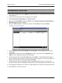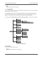
1
TOTAL ACCESS 544R
System Manual
4200704L2#ATM Total Access 544R ATM
1200704L3
Total Access 544R without Power Cord
4200704L8
Total Access 544R with Euro Power Cord
4200704L9
Total Access 544R Total Access 544R with UK Power Cord
4200704L10
Total Access 544R with Australian Power Cord
4200704L11
Total Access 544R with US Power Cord
61200704L2-1B
July 2003
Trademarks
Total Access 544R System Manual
Trademarks
Any brand names and product names included in this manual are trademarks, registered trademarks, or
trade names of their respective holders.
To the Holder of the Manual
The contents of this manual are current as of the date of publication. ADTRAN reserves the right to change
the contents without prior notice.
In no event will ADTRAN be liable for any special, incidental, or consequential damages or for
commercial losses even if ADTRAN has been advised thereof as a result of issue of this publication.
About this Manual
This manual provides a complete description of the Total Access 544R system and system software. The
purpose of this manual is to provide the technician, system administrator, and manager with general and
specific information related to the planning, installation, operation, and maintenance of the Total Access
544R. This manual is arranged so that needed information can be quickly and easily found.
901 Explorer Boulevard
P.O. Box 140000
Huntsville, AL 35814-4000
Phone: (256) 963-8000
© 2003 ADTRAN, Inc.
All Rights Reserved.
Printed in U.S.A.
2
© 2003 ADTRAN, Inc.
61200704L2-1B
Total Access 544R System Manual
Revision History
Revision History
This is the second issue of this manual.
Conventions
Notes provide additional useful information.
Cautions signify information that could prevent service interruption.
Warnings provide information that could prevent damage to the equipment or
endangerment to human life.
61200704L2-1B
© 2003 ADTRAN, Inc.
3
Safety Instructions
Total Access 544R System Manual
Safety Instructions
When using your telephone equipment, please follow these basic safety precautions to reduce the risk of
fire, electrical shock, or personal injury:
1. Do not use this product near water, such as a bathtub, wash bowl, kitchen sink, laundry tub, in a
wet basement, or near a swimming pool.
2. Avoid using a telephone (other than a cordless-type) during an electrical storm. There is a remote
risk of shock from lightning.
3. Do not use the telephone to report a gas leak in the vicinity of the leak.
4. Use only the power cord, power supply, and/or batteries indicated in the manual. Do not dispose of
batteries in a fire. They may explode. Check with local codes for special disposal instructions.
Save These Important Safety Instructions
4
© 2003 ADTRAN, Inc.
61200704L2-1B
Total Access 544R System Manual
Save These Important Safety Instructions
Federal Communications Commission Radio Frequency Interference Statement
This equipment has been tested and found to comply with the limits for a Class A digital device, pursuant
to Part 15 of the FCC Rules. These limits are designed to provide reasonable protection against harmful
interference when the equipment is operated in a commercial environment. This equipment generates,
uses, and can radiate radio frequency energy and, if not installed and used in accordance with the
instruction manual, may cause harmful interference to radio frequencies. Operation of this equipment in a
residential area is likely to cause harmful interference in which case the user will be required to correct the
interference at his own expense.
Shielded cables must be used with this unit to ensure compliance with Class A FCC limits.
Changes or modifications to this unit not expressly approved by the party responsible
for compliance could void the user’s authority to operate the equipment.
61200704L2-1B
© 2003 ADTRAN, Inc.
5
Affidavit Requirements for Connection to Digital Services
Total Access 544R System Manual
Affidavit Requirements for Connection to Digital Services
•
An affidavit is required to be given to the telephone company whenever digital terminal equipment
without encoded analog content and billing protection is used to transmit digital signals containing
encoded analog content which are intended for eventual conversion into voiceband analog signals and
transmitted on the network.
•
The affidavit shall affirm that either no encoded analog content or billing information is being
transmitted or that the output of the device meets Part 68 encoded analog content or billing protection
specifications.
•
End user/customer will be responsible for filing an affidavit with the local exchange carrier when
connecting unprotected customer premise equipment (CPE) to 1.544 Mbps or subrate digital services.
•
Until such time as subrate digital terminal equipment is registered for voice applications, the affidavit
requirement for subrate services is waived.
6
© 2003 ADTRAN, Inc.
61200704L2-1B
Total Access 544R System Manual
Affidavit Requirements for Connection to Digital Services
Affidavit for Connection of Customer Premises Equipment to 1.544 Mbps and/or Subrate Digital
Services
For the work to be performed in the certified territory of ___________________ (telco name)
State of ________________
County of ________________
I, _______________________ (name), ____________________________________ (business address),
____________________ (telephone number) being duly sworn, state:
I have responsibility for the operation and maintenance of the terminal equipment to be connected
to 1.544 Mbps and/or ________ subrate digital services. The terminal equipment to be connected
complies with Part 68 of the FCC rules except for the encoded analog content and billing protection
specifications. With respect to encoded analog content and billing protection:
I attest that all operations associated with the establishment, maintenance, and adjustment of the
digital CPE with respect to analog content and encoded billing protection information continuously
complies with Part 68 of the FCC Rules and Regulations.
The digital CPE does not transmit digital signals containing encoded analog content or billing
information which is intended to be decoded within the telecommunications network.
The encoded analog content and billing protection is factory set and is not under the control of the
customer.
I attest that the operator(s)/maintainer(s) of the digital CPE responsible for the establishment,
maintenance, and adjustment of the encoded analog content and billing information has (have) been
trained to perform these functions by successfully having completed one of the following (check
appropriate blocks):
A training course provided by the manufacturer/grantee of the equipment used to encode analog
signals; or
A training course provided by the customer or authorized representative, using training materials
and instructions provided by the manufacturer/grantee of the equipment used to encode analog
signals; or
An independent training course (e.g., trade school or technical institution) recognized by the
manufacturer/grantee of the equipment used to encode analog signals; or
In lieu of the preceding training requirements, the operator(s)/maintainer(s) is (are) under the
control of a supervisor trained in accordance with _________ (circle one) above.
I agree to provide ______________________ (telco’s name) with proper documentation to
demonstrate compliance with the information as provided in the preceding paragraph, if so
requested.
_________________________________Signature
_________________________________Title
_________________________________ Date
Transcribed and sworn to before me
61200704L2-1B
© 2003 ADTRAN, Inc.
7
Affidavit Requirements for Connection to Digital Services
Total Access 544R System Manual
This ________ day of _______________, _______
_________________________________
Notary Public
My commission expires:
_________________________________
8
© 2003 ADTRAN, Inc.
61200704L2-1B
Total Access 544R System Manual
Industry Canada Compliance Information
Industry Canada Compliance Information
Notice: The Industry Canada label applied to the product (identified by the Industry Canada logo or the
“IC:” in front of the certification/registration number) signifies that the Industry Canada technical
specifications were met.
Notice: The Ringer Equivalence Number (REN) for this terminal equipment is supplied in the
documentation or on the product labeling/markings. The REN assigned to each terminal device indicates
the maximum number of terminals that can be connected to a telephone interface. The termination on an
interface may consist of any combination of devices subject only to the requirement that the sum of the
RENs of all the devices should not exceed five (5).
Canadian Emissions Requirements
This digital apparatus does not exceed the Class A limits for radio noise emissions from digital apparatus
as set out in the interference-causing equipment standard entitled “Digital Apparatus,” ICES-003 of the
Department of Communications.
Cet appareil numérique respecte les limites de bruits radioelectriques applicables aux appareils numériques
de Class A prescrites dans la norme sur le materiel brouilleur: “Appareils Numériques,” NMB-003 edictee
par le ministre des Communications.
61200704L2-1B
© 2003 ADTRAN, Inc.
9
Product Warranty
Total Access 544R System Manual
Product Warranty
ADTRAN will replace or repair this product within the warranty period if it does not meet its published
specifications or fails while in service. Warranty information can be found at www.adtran.com/warranty.
Product Registration
Registering your product helps ensure complete customer satisfaction. Please take time to register your
products on line at www.adtran.com. Click Service and Support on the top of the page, and then click
Product Registration under Support.
Customer Service, Product Support Information, and Training
ADTRAN will replace or repair this product within the warranty period if it does not meet its published
specifications or fails while in service. Warranty information can be found at www.adtran.com/warranty.
A return material authorization (RMA) is required prior to returning equipment to ADTRAN. For service,
RMA requests, training, or more information, use the contact information given below.
Repair and Return
If you determine that a repair is needed, please contact our Customer and Product Service (CAPS)
department to have an RMA number issued. CAPS should also be contacted to obtain information
regarding equipment currently in house or possible fees associated with repair.
CaPS Department
(256) 963-8722
Identify the RMA number clearly on the package (below address), and return to the following address:
ADTRAN Customer and Product Service
901 Explorer Blvd. (East Tower)
Huntsville, Alabama 35806
RMA # _____________
Pre-Sales Inquiries and Applications Support
Your reseller should serve as the first point of contact for support. If additional pre-sales support is needed,
the ADTRAN Support web site provides a variety of support services such as a searchable knowledge
base, latest product documentation, application briefs, case studies, and a link to submit a question to an
Applications Engineer. All of this, and more, is available at:
http://support.adtran.com
When needed, further pre-sales assistance is available by calling our Applications Engineering
Department.
Applications Engineering (800) 615-1176
10
© 2003 ADTRAN, Inc.
61200704L2-1B
Total Access 544R System Manual
Customer Service, Product Support Information, and Training
Post-Sale Support
Your reseller should serve as the first point of contact for support. If additional support is needed, the
ADTRAN Support web site provides a variety of support services such as a searchable knowledge base,
updated firmware releases, latest product documentation, service request ticket generation and
trouble-shooting tools. All of this, and more, is available at:
http://support.adtran.com
When needed, further post-sales assistance is available by calling our Technical Support Center. Please
have your unit serial number available when you call.
Technical Support
(888) 4ADTRAN
Installation and Maintenance Support
The ADTRAN Custom Extended Services (ACES) program offers multiple types and levels of installation
and maintenance services which allow you to choose the kind of assistance you need. This support is
available at:
http://www.adtran.com/aces
For questions, call the ACES Help Desk.
ACES Help Desk
(888) 874-ACES (2237)
Training
The Enterprise Network (EN) Technical Training Department offers training on our most popular products.
These courses include overviews on product features and functions while covering applications of
ADTRAN's product lines. ADTRAN provides a variety of training options, including customized training
and courses taught at our facilities or at your site. For more information about training, please contact your
Territory Manager or the Enterprise Training Coordinator.
61200704L2-1B
Training Phone
(800) 615-1176, ext. 7500
Training Fax
(256) 963-6700
Training Email
[email protected]
© 2003 ADTRAN, Inc.
11
Customer Service, Product Support Information, and Training
12
© 2003 ADTRAN, Inc.
Total Access 544R System Manual
61200704L2-1B
Table of Contents
Section 1
System Description . . . . . . . . . . . . . . . . . . . . . . . . . . . . . . . . . . . . . . . . 15
This section of ADTRAN’s Product System Manual is designed for use by network engineers,
planners, and designers for overview information about the Product.
It contains general information and describes the L2 protocol support, routing capability, security, and testing features. This section should be used in conjunction with Section 2, Engineering
Guidelines, of this System Manual.
Section 2
Engineering Guidelines . . . . . . . . . . . . . . . . . . . . . . . . . . . . . . . . . . . . . 19
Provides equipment dimensions, power requirements, front panel design, rear panel design,
LEDs, and at-a-glance specifications.
Section 3
Network Turnup Procedure . . . . . . . . . . . . . . . . . . . . . . . . . . . . . . . . . . 25
Provides shipment contents list, grounding instructions, mounting options, and specifics of supplying power to the unit.
Section 4
SHDSL RCU ATM User Interface Guide . . . . . . . . . . . . . . . . . . . . . . . . 29
The SHDSL RCU ATM User Interface Guide is designed for use by network administrators and
others who will configure and provision the system. This section provides details unique to the
SHDSL RCU ATM firmware. It contains an overview, application details, configuration information, and menu
Section 5
Detail Level Procedures. . . . . . . . . . . . . . . . . . . . . . . . . . . . . . . . . . . . . 95
DLP-1
DLP-2
DLP-3
DLP-4
DLP-5
DLP-6
DLP-7
DLP-8
DLP-9
DLP-10
DLP-11
DLP-12
DLP-13
DLP-14
DLP-15
Section 6
Connecting the Terminal or PC to the CRAFT Port . . . . . . . . . . . . . . . . . . . . . . . . . . . 97
Logging in to the System . . . . . . . . . . . . . . . . . . . . . . . . . . . . . . . . . . . . . . . . . . . . . . 101
Adding/Removing Telnet Users and Changing Password Security Levels . . . . . . . . 105
Setting Ethernet IP Parameters . . . . . . . . . . . . . . . . . . . . . . . . . . . . . . . . . . . . . . . . . . 109
Verifying Communications Over an IP LAN . . . . . . . . . . . . . . . . . . . . . . . . . . . . . . . 111
Telnetting to the Unit . . . . . . . . . . . . . . . . . . . . . . . . . . . . . . . . . . . . . . . . . . . . . . . . . 115
Upgrading the Firmware Using XMODEM . . . . . . . . . . . . . . . . . . . . . . . . . . . . . . . . 119
Upgrading the Firmware Using TFTP . . . . . . . . . . . . . . . . . . . . . . . . . . . . . . . . . . . . 121
Saving the Current Configuration Using TFTP . . . . . . . . . . . . . . . . . . . . . . . . . . . . . 125
Loading the Current Configuration Using TFTP . . . . . . . . . . . . . . . . . . . . . . . . . . . . 129
Saving the Current Configuration Using XMODEM . . . . . . . . . . . . . . . . . . . . . . . . . 133
Loading the Current Configuration Using XMODEM . . . . . . . . . . . . . . . . . . . . . . . . 135
Saving and Loading Text Configuration Using the Terminal Command Line. . . . . . 137
Unit Installation Using The Auto-Config Feature. . . . . . . . . . . . . . . . . . . . . . . . . . . . 141
A.03 to A.04 Firmware Upgrade. . . . . . . . . . . . . . . . . . . . . . . . . . . . . . . . . . . . . . . . . 145
ADTRAN Utilities . . . . . . . . . . . . . . . . . . . . . . . . . . . . . . . . . . . . . . . . . 149
Provides instructions for configuring and using the ADTRAN Utilities software programs including Telnet, VT100, Syslog, and TFTP.
Section 7
MIBs. . . . . . . . . . . . . . . . . . . . . . . . . . . . . . . . . . . . . . . . . . . . . . . . . . . . 159
Provides a listing of SNMP Management Information Bases (MIBs) supported by the Total Access 544R. Traps supported for each MIB are also listed.
61200704L2-1B
© 2003 ADTRAN, Inc.
13
Table of Contents
14
Total Access 544R System Manual
© 2003 ADTRAN, Inc.
61200704L2-1B
SYSTEM DESCRIPTION
This section of ADTRAN’s Product System Manual is designed for use by network engineers, planners,
and designers for overview information about the Product.
It contains general information and describes the L2 protocol support, routing capability, security, and
testing features. This section should be used in conjunction with Section 2, Engineering Guidelines, of this
System Manual.
CONTENTS
Firmware Updates. . . . . . . . . . . . . . . . . . . . . . . . . . . . . . . . . . . . . . . . . . . . . . . . . . . . . . . . . . . . 16
Terminal Menu . . . . . . . . . . . . . . . . . . . . . . . . . . . . . . . . . . . . . . . . . . . . . . . . . . . . . . . . . . . . . . 16
Features and Benefits . . . . . . . . . . . . . . . . . . . . . . . . . . . . . . . . . . . . . . . . . . . . . . . . . . . . . . . . . . . 16
Configuration and Management . . . . . . . . . . . . . . . . . . . . . . . . . . . . . . . . . . . . . . . . . . . . . . . . . 16
Software Upgradeable . . . . . . . . . . . . . . . . . . . . . . . . . . . . . . . . . . . . . . . . . . . . . . . . . . . . . . . . 17
Network Interface . . . . . . . . . . . . . . . . . . . . . . . . . . . . . . . . . . . . . . . . . . . . . . . . . . . . . . . . . . . . 17
LAN Interface . . . . . . . . . . . . . . . . . . . . . . . . . . . . . . . . . . . . . . . . . . . . . . . . . . . . . . . . . . . . . . . 17
Protocol Support . . . . . . . . . . . . . . . . . . . . . . . . . . . . . . . . . . . . . . . . . . . . . . . . . . . . . . . . . . . . . 17
ATM Support . . . . . . . . . . . . . . . . . . . . . . . . . . . . . . . . . . . . . . . . . . . . . . . . . . . . . . . . . . . . . . . . 18
PPP . . . . . . . . . . . . . . . . . . . . . . . . . . . . . . . . . . . . . . . . . . . . . . . . . . . . . . . . . . . . . . . . . . . . . . . 18
Routing Capability . . . . . . . . . . . . . . . . . . . . . . . . . . . . . . . . . . . . . . . . . . . . . . . . . . . . . . . . . . . . 18
Security . . . . . . . . . . . . . . . . . . . . . . . . . . . . . . . . . . . . . . . . . . . . . . . . . . . . . . . . . . . . . . . . . . . . 18
Integrated Components. . . . . . . . . . . . . . . . . . . . . . . . . . . . . . . . . . . . . . . . . . . . . . . . . . . . . . . . 18
61200704L2-1B
© 2003 ADTRAN, Inc.
15
Section 1 System Description
1.
Total Access 544R System Manual
SYSTEM OVERVIEW
The Total Access 544R is a cost-effective SHDSL access router designed for small and medium
businesses, branch offices and campuses. The unit provides up to 2312 kbps for dedicated Internet access
or remote office connectivity. With its integrated CSU/DSU, the Total Access 544R provides wide area
network access over a standard SHDSL or fractional SHDSL circuit.
Multiple users can share network access over a single SHDSL connection. For simultaneous access to
both a corporate network and the public Internet, the unit offers the ability to configure multiple PVCs. In
addition, the unit includes NAT/NAPT and IP filtering which provides security from unauthorized access
to the user's network.
The Total Access 544R also provides a cost-effective campus connectivity solution. When used with
private dry copper, the unit delivers up to 2.3 Mbps to cross-campus network elements. This solution is
ideal for extending LAN segments to other buildings.
Other features include a DHCP server, TELNET support, SNMP support, ping utility, and software
upgrades via TFTP and XMODEM.
Until now, the Total Access 544R unit has been running firmware version A.00.XX. Recently, D.04.XX
has been released. The development of D.04.XX code is a significant step in the evolution of the Total
Access product line, as it allows all Total Access family members to share the same base code. This means
that features and fixes are more easily implemented and are propagated across the product line. Section 4,
SHDSL ATM User Interface Guide, of this manual represents the D.04 firmware.
Firmware Updates
Firmware can be updated by using XMODEM transfer protocol via the unit’s CRAFT port or by using
TFTP from a network server.
Terminal Menu
The terminal menu is the access point to all other operations. Each terminal menu item has several
functions and submenus that identify and provide access to specific operations and parameters. These
menu selections are described later in this System Manual.
2.
FEATURES AND BENEFITS
Below is a list of unit features and benefits.
Configuration and Management
•
•
•
•
•
•
16
VT100 emulation via the CRAFT port
Telnet
SNMP
LAN and WAN status LEDs
Text-based configuration file support
Syslog client
© 2003 ADTRAN, Inc.
61200704L2-1B
Total Access 544R System Manual
•
•
Section 1 System Description
ICMP Ping utility
Trace route utility
Software Upgradeable
•
•
TFTP download
XMODEM via CRAFT port
Network Interface
G.shdsl: (ITU G.991.2 Compliant)
• Line Rate: 200- 2312 kbps (3-36 DS0s)
• Physical Interface: RJ-48C
• Rate Adaptive
• Improved Spectral Compatibility
• Echo Cancellation
LAN Interface
•
•
•
•
•
•
10/100 BaseT
Half or Full Duplex
RJ-45
Secondary IP address
DHCP server
IEEE 802.3
Protocol Support
•
•
•
•
•
•
•
•
•
IP
DNS
TCP
RIP V1, V2 and static routes
UDP, UDP Relay
ICMP
ARP
PPP
Frame Relay
61200704L2-1B
© 2003 ADTRAN, Inc.
17
Section 1 System Description
Total Access 544R System Manual
ATM Support
•
•
•
•
•
•
6 PVCs
IP over ATM (RFC 1483)
RFC 1483 (Multiprotocol Encapsulation over ATM), PPPoA (RFC 2364)
Full Traffic Shaping and QoS Support
VBR-rt and UBR Support
F5 OAM Loopback Capability
PPP
•
•
LCP, IPCP, BCP, CCP
Van Jacobson (VJ) header compression
Routing Capability
•
•
•
•
•
Ethernet: 10/100BaseT (RJ-45)
IEEE 802.3 and 802.1D (MAC Bridging)
IP Support: TCP, RIP V1, RIP V2, UDP, ICMP, ARP, UDP Relay, SYSLOG
PPP Support: LCP, IPCP, BCP
DHCP Server to LAN, DHCP from network (NAT)
Security
•
•
•
•
•
PAP, CHAP, EAP, and Radius
NAT/NAPT
Packet filtering by source and destination IP address, source and destination port number, MAC
address, protocol or pattern
Multi-layer Password protection
Telnet security: Access list and password protection
Integrated Components
•
•
•
•
18
IP router
Network connection
10/100BaseT connection
CRAFT port
© 2003 ADTRAN, Inc.
61200704L2-1B
ENGINEERING GUIDELINES
Provides equipment dimensions, power requirements, front panel design, rear panel design, LEDs, and
at-a-glance specifications.
CONTENTS
Reviewing the Front Panel Design . . . . . . . . . . . . . . . . . . . . . . . . . . . . . . . . . . . . . . . . . . . . . . . . . 20
Front Panel LEDs . . . . . . . . . . . . . . . . . . . . . . . . . . . . . . . . . . . . . . . . . . . . . . . . . . . . . . . . . . . . 20
Reviewing the Rear Panel Design . . . . . . . . . . . . . . . . . . . . . . . . . . . . . . . . . . . . . . . . . . . . . . . . . . 21
NTWK Connection (RJ-48C). . . . . . . . . . . . . . . . . . . . . . . . . . . . . . . . . . . . . . . . . . . . . . . . . . . . 21
CRAFT Port (RJ-48C) . . . . . . . . . . . . . . . . . . . . . . . . . . . . . . . . . . . . . . . . . . . . . . . . . . . . . . . . . 21
10/100BASET Connection (RJ-48C). . . . . . . . . . . . . . . . . . . . . . . . . . . . . . . . . . . . . . . . . . . . . . 22
AC Power Connection. . . . . . . . . . . . . . . . . . . . . . . . . . . . . . . . . . . . . . . . . . . . . . . . . . . . . . . . . 22
DB-9 to RJ Adapter . . . . . . . . . . . . . . . . . . . . . . . . . . . . . . . . . . . . . . . . . . . . . . . . . . . . . . . . . . . . . . 23
Figure 1.
Figure 2.
FIGURES
Total Access 544R Front Panel Layout . . . . . . . . . . . . . . . . . . . . . . . . . . . . . . . . . . . . . 20
Total Access 544R Rear Panel . . . . . . . . . . . . . . . . . . . . . . . . . . . . . . . . . . . . . . . . . . . 21
Table 1.
Table 2.
Table 3.
Table 4.
Table 5.
TABLES
Total Access 544R Front Panel LEDs . . . . . . . . . . . . . . . . . . . . . . . . . . . . . . . . . . . . . . . 20
SHDSL NTWK Connection Pinout . . . . . . . . . . . . . . . . . . . . . . . . . . . . . . . . . . . . . . . . . 21
CRAFT Pinout . . . . . . . . . . . . . . . . . . . . . . . . . . . . . . . . . . . . . . . . . . . . . . . . . . . . . . . . . 22
10/100BASET Pinout . . . . . . . . . . . . . . . . . . . . . . . . . . . . . . . . . . . . . . . . . . . . . . . . . . . 22
DB-9 to RJ Adapter Pinout . . . . . . . . . . . . . . . . . . . . . . . . . . . . . . . . . . . . . . . . . . . . . . . 23
EQUIPMENT DIMENSIONS
The Total Access 544R measures 11.25” W, 7.5” D, and 2” H and comes equipped for table top or wall
mount use.
61200704L2-1B
© 2003 ADTRAN, Inc.
19
Section 2 Engineering Guidelines
1.
Total Access 544R System Manual
POWER REQUIREMENTS
The Total Access 544R operates with 240 VAC, 50 Hz and a maximum current drain of 300 mA. The Total
Access 544R maximum power consumption shall not exceed 10 Watts.
2.
REVIEWING THE FRONT PANEL DESIGN
Figure 1. shows the front panel of the Total Access 544R which contains the LAN, WAN, and power
LEDs. These LEDs and their functions are described in Table 1.
.
LAN
WAN
Figure 1. Total Access 544R Front Panel Layout
Front Panel LEDs
The front panel provides five status LEDs to monitor operation and activity. The following table provides
LED activity explanations.
Table 1. Total Access 544R Front Panel LEDs
For these LEDs...
This color light...
Indicates that...
LAN TX/RX
Off
there is no data traffic on the LAN.
Green (blinking)
there is data traffic on the LAN.
Off
the physical link is down; there is no Ethernet
connection.
Green (solid)
there is link integrity on the LAN (physical link is up).
Red (solid)
the SHDSL is shut down.
Green (solid)
the SHDSL is up.
Red (flashing)
the SHDSL is down.
Yellow (solid)
errors are present on the WAN link.
Red (solid)
severe errors are present on the WAN link.
Off
the WAN link is up and error-free.
Green (solid)
power is supplied to the unit.
Off
power is not supplied to the unit.
LAN LINK
WAN STAT
WAN ERR
PWR
20
© 2003 ADTRAN, Inc.
61200704L2-1B
Total Access 544R System Manual
3.
Section 2 Engineering Guidelines
REVIEWING THE REAR PANEL DESIGN
The Total Access 544R rear panel is shown in Figure 2..
Figure 2. Total Access 544R Rear Panel
NTWK Connection (RJ-48C)
The NTWK connection pinout is an SHDSL connection. Table 1 shows the pinout for this connection.
Connector type
RJ-48C
Table 2. SHDSL NTWK Connection Pinout
PIN
DESCRIPTION
1-3
Not Used
4
Ring
5
Tip
6-8
Not Used
CRAFT Port (RJ-48C)
The CRAFT port connects to a computer or modem. The CRAFT port input provides the following
functions:
• Accepts input from a PC or a modem for controlling the unit.
• Operates at 300, 1200, 2400, 4800, 9600, 19200, 38400, 57600, and 115200 bps.
• Acts as input for either VT100 or PC control.
• Acts as an interface for flash memory software downloads using XMODEM.
Table 3 shows the CRAFT port pinout.
61200704L2-1B
© 2003 ADTRAN, Inc.
21
Section 2 Engineering Guidelines
Total Access 544R System Manual
Table 3. CRAFT Pinout
PIN
NAME
DESCRIPTION
1
GND
Ground - connected to unit chassis
2
RTS
Request to send - flow control
3
RXDATA
Data received by the unit.
4
DTR
Data terminal ready
5
TXDATA
Data transmitted by the unit.
6
CD
Carrier detect
7
UNUSED
—
8
CTS
Clear to send - flow control
10/100BASET Connection (RJ-48C)
The 10/100BASET port (RJ-48C) provides a 10/100BaseT Ethernet LAN connection, which is used for IP
Routing, TFTP, SNMP, and Telnet connections. Table 4 shows the 10/100BASET port pinout.
Table 4. 10/100BASET Pinout
PIN
NAME
DESCRIPTION
1
TX1
Transmit Positive
2
TX2
Transmit Negative
3
RX1
Receive Positive
4, 5
UNUSED
—
6
RX2
Receive Negative
7, 8
UNUSED
—
AC Power Connection
Each unit includes an auto ranging 100-250 VAC, 50/60 Hz power supply with a 3-prong removable cable.
Connect the power supply to a standard 120 VAC, 60 Hz electrical outlet for proper operation.
22
© 2003 ADTRAN, Inc.
61200704L2-1B
Total Access 544R System Manual
4.
Section 2 Engineering Guidelines
DB-9 TO RJ ADAPTER
The DB-9 to RJ adapter is used to connect a PC or VT100 terminal to the CRAFT port. The adapter pinout
is shown in Table 5.
Table 5. DB-9 to RJ Adapter Pinout
DB-9
RJ-45
DESCRIPTION
2
5
TX Data
3
3
RX Data
5
1
GND
Note: All other pins are unused.
61200704L2-1B
© 2003 ADTRAN, Inc.
23
Section 2 Engineering Guidelines
24
Total Access 544R System Manual
© 2003 ADTRAN, Inc.
61200704L2-1B
NETWORK TURNUP PROCEDURE
Provides shipment contents list, grounding instructions, mounting options, and specifics of supplying
power to the unit.
CONTENTS
Tools Required . . . . . . . . . . . . . . . . . . . . . . . . . . . . . . . . . . . . . . . . . . . . . . . . . . . . . . . . . . . . . . . . . 26
Unpack and Inspect the System . . . . . . . . . . . . . . . . . . . . . . . . . . . . . . . . . . . . . . . . . . . . . . . . . . . 26
Contents of ADTRAN Shipment . . . . . . . . . . . . . . . . . . . . . . . . . . . . . . . . . . . . . . . . . . . . . . . . . 26
Grounding Instructions . . . . . . . . . . . . . . . . . . . . . . . . . . . . . . . . . . . . . . . . . . . . . . . . . . . . . . . . . . 27
Supplying Power to the Unit . . . . . . . . . . . . . . . . . . . . . . . . . . . . . . . . . . . . . . . . . . . . . . . . . . . . . . 28
Mounting Options . . . . . . . . . . . . . . . . . . . . . . . . . . . . . . . . . . . . . . . . . . . . . . . . . . . . . . . . . . . . . . . 28
61200704L2-1B
© 2003 ADTRAN, Inc.
25
Section 3 Network Turnup Procedure
1.
Total Access 544R System Manual
INTRODUCTION
This section discusses the unit installation process.
2.
TOOLS REQUIRED
The tools required for unit installation are:
• Screws (customer-provided for wallmount installation)
• Screwdriver (for wall or rackmount installation)
To prevent electrical shock, do not install equipment in a wet location or during a
lightning storm.
During installation, power should be the last connection made.
Electronic modules can be damaged by static electrical discharge. Before handling
modules, wear an antistatic discharge wrist strap to prevent damage to electrical
components. Place modules in antistatic packing material when transporting or storing.
When working on modules, always place them on an approved antistatic mat that is
electrically grounded.
3.
UNPACK AND INSPECT THE SYSTEM
Each unit is shipped in its own cardboard shipping carton. Open each carton carefully and avoid deep
penetration into the carton with sharp objects.
After unpacking the unit, inspect it for possible shipping damage. If the equipment has been damaged in
transit, immediately file a claim with the carrier, and then contact ADTRAN Customer Service (see the
contact information in the front of this manual).
Contents of ADTRAN Shipment
Your ADTRAN shipment of the Total Access 544R includes the following items:
• Mounting Instructions (P/N 64200600L1#T-19A)
• CD
• Cable Tie (P/N 3292032)
• Silver Satin Cable (P/N 3127004)
• Four Rubber Feet (P/N 3270BF003)
• Power Cord (P/N 3127009)
• 2 Mounting Brackets (P/N 3265421@C)
26
© 2003 ADTRAN, Inc.
61200704L2-1B
Total Access 544R System Manual
•
•
•
Section 3 Network Turnup Procedure
4 Screws (P/N 3276003003)
RJ-45 to DB-9 Adapter (P/N 3196ADPT001)
The Total Access 544R base unit
Customers must supply the Ethernet cable.
4.
GROUNDING INSTRUCTIONS
The following provides grounding instruction information from the Underwriters’ Laboratory UL60950
Standard for Safety of Information Technology Equipment Including Electrical Business Equipment, Third
Edition, of December 1, 2000.
An equipment grounding conductor that is not smaller in size than the ungrounded branch-circuit supply
conductors is to be installed as part of the circuit that supplies the product or system. Bare, covered, or
insulated grounding conductors are acceptable. Individually covered or insulated equipment grounding
conductors shall have a continuous outer finish that is either green, or green with one or more yellow
stripes. The equipment grounding conductor is to be connected to ground at the service equipment.
The attachment-plug receptacles in the vicinity of the product or system are all to be of a grounding type,
and the equipment grounding conductors serving these receptacles are to be connected to earth ground at
the service equipment.
A supplementary equipment grounding conductor shall be installed between the product or system and
ground that is in addition to the equipment grounding conductor in the power supply cord.
The supplementary equipment grounding conductor shall not be smaller in size than the ungrounded
branch-circuit supply conductors. The supplementary equipment grounding conductor shall be connected
to the product at the terminal provided, and shall be connected to ground in a manner that will retain the
ground connection when the product is unplugged from the receptacle. The connection to ground of the
supplementary equipment grounding conductor shall be in compliance with the rules for terminating
bonding jumpers at Part K or Article 250 of the National Electrical Code, ANSI/NFPA 70. Termination of
the supplementary equipment grounding conductor is permitted to be made to building steel, to a metal
electrical raceway system, or to any grounded item that is permanently and reliably connected to the
electrical service equipment ground.
The supplemental grounding conductor shall be connected to the equipment using a number 8 ring terminal
and should be fastened to the grounding lug provided on the rear panel of the equipment. The ring terminal
should be installed using the appropriate crimping tool (AMP P/N 59250 T-EAD Crimping Tool or
equivalent).
• This unit shall be installed in accordance with Article 400 and 364.8 of the NEC NFPA
70 when installed outside of a Restricted Access Location (i.e., central office, behind a
locked door, service personnel only area).
• Power to the unit’s AC system must be from a grounded 100-250 VAC, 50/60 Hz source.
• The power receptacle uses double-pole, neutral fusing.
• Maximum recommended ambient operating temperature is 45 ºC.
61200704L2-1B
© 2003 ADTRAN, Inc.
27
Section 3 Network Turnup Procedure
5.
Total Access 544R System Manual
SUPPLYING POWER TO THE UNIT
The AC powered unit comes equipped with a detachable power cord with a 3-prong plug for connecting to
a grounded power receptacle. As shipped, the unit is set to factory default conditions. After installing the
chassis, the unit is ready for power-up. To power-up the unit, ensure that the unit is properly connected to
an appropriate power source.
6.
MOUNTING OPTIONS
The Total Access 544R comes equipped for table top or wallmount use. The unit is shipped with two
wall-mount brackets (P/N 326542@C) and four screws (P/N 3276003003) which the customer must attach
to the base unit for wallmount use.
If wallmounted, the Total Access 544R must be mounted with the LEDs pointing
down or sideways as shown in the mounting instructions (P/N 64200600L1#T-19A).
28
© 2003 ADTRAN, Inc.
61200704L2-1B
SHDSL RCU ATM USER INTERFACE GUIDE
The SHDSL RCU ATM User Interface Guide is designed for use by network administrators and others who
will configure and provision the system. This section provides details unique to the SHDSL RCU ATM
firmware. It contains an overview, application details, configuration information, and menu
CONTENTS
System Info . . . . . . . . . . . . . . . . . . . . . . . . . . . . . . . . . . . . . . . . . . . . . . . . . . . . . . . . . . . . . . . . . . .
System Config. . . . . . . . . . . . . . . . . . . . . . . . . . . . . . . . . . . . . . . . . . . . . . . . . . . . . . . . . . . . . . .
System Utility . . . . . . . . . . . . . . . . . . . . . . . . . . . . . . . . . . . . . . . . . . . . . . . . . . . . . . . . . . . . . . .
Interfaces (SHDSL) . . . . . . . . . . . . . . . . . . . . . . . . . . . . . . . . . . . . . . . . . . . . . . . . . . . . . . . . . . .
Interfaces (ETH) . . . . . . . . . . . . . . . . . . . . . . . . . . . . . . . . . . . . . . . . . . . . . . . . . . . . . . . . . . . . .
L2 Protocol . . . . . . . . . . . . . . . . . . . . . . . . . . . . . . . . . . . . . . . . . . . . . . . . . . . . . . . . . . . . . . . . .
L2 Protocol (SHDSL). . . . . . . . . . . . . . . . . . . . . . . . . . . . . . . . . . . . . . . . . . . . . . . . . . . . . . . . . .
L2 Protocol (ETH) . . . . . . . . . . . . . . . . . . . . . . . . . . . . . . . . . . . . . . . . . . . . . . . . . . . . . . . . . . . .
Bridge . . . . . . . . . . . . . . . . . . . . . . . . . . . . . . . . . . . . . . . . . . . . . . . . . . . . . . . . . . . . . . . . . . . . .
Router . . . . . . . . . . . . . . . . . . . . . . . . . . . . . . . . . . . . . . . . . . . . . . . . . . . . . . . . . . . . . . . . . . . . .
Security . . . . . . . . . . . . . . . . . . . . . . . . . . . . . . . . . . . . . . . . . . . . . . . . . . . . . . . . . . . . . . . . . . . .
30
32
46
53
55
56
56
63
65
67
83
Figure 1.
Figure 2.
Figure 3.
Figure 4.
Figure 5.
Figure 6.
Figure 7.
Figure 8.
Figure 9.
FIGURES
System Info Menu . . . . . . . . . . . . . . . . . . . . . . . . . . . . . . . . . . . . . . . . . . . . . . . . . . . . .
System Config Menu . . . . . . . . . . . . . . . . . . . . . . . . . . . . . . . . . . . . . . . . . . . . . . . . . . .
System Utility Menu . . . . . . . . . . . . . . . . . . . . . . . . . . . . . . . . . . . . . . . . . . . . . . . . . . . .
Interfaces Menu . . . . . . . . . . . . . . . . . . . . . . . . . . . . . . . . . . . . . . . . . . . . . . . . . . . . . . .
L2 Protocol Menu . . . . . . . . . . . . . . . . . . . . . . . . . . . . . . . . . . . . . . . . . . . . . . . . . . . . . .
Bridge Menu. . . . . . . . . . . . . . . . . . . . . . . . . . . . . . . . . . . . . . . . . . . . . . . . . . . . . . . . . .
Router Menu . . . . . . . . . . . . . . . . . . . . . . . . . . . . . . . . . . . . . . . . . . . . . . . . . . . . . . . . .
Security Menu . . . . . . . . . . . . . . . . . . . . . . . . . . . . . . . . . . . . . . . . . . . . . . . . . . . . . . . .
Application Diagrams . . . . . . . . . . . . . . . . . . . . . . . . . . . . . . . . . . . . . . . . . . . . . . . . . . .
30
32
46
53
56
66
68
83
90
Table 1.
Table 2.
TABLES
Instructions for Changing Passwords . . . . . . . . . . . . . . . . . . . . . . . . . . . . . . . . . . . . . . . 33
Telnet Security Levels . . . . . . . . . . . . . . . . . . . . . . . . . . . . . . . . . . . . . . . . . . . . . . . . . . . 35
61200704L2-1B
© 2003 ADTRAN, Inc.
29
Section 4 SHDSL RCU ATM User Interface Guide
1.
Total Access 544R System Manual
SYSTEM INFO
The System Info menu provides basic information about the unit as well as data fields for editing
information. Figure 1 displays the submenus that are available when you select this menu item.
Figure 1. System Info Menu
SYSTEM INFO > SYSTEM NAME
Provides a user-configurable text string for the name of the unit. This name can help you distinguish
between different installations. You can enter up to 31 alpha-numeric characters in this field, including
spaces and special characters (such as an underscore). This name will appear on the top line of all screens.
This field is blank by default.
SYSTEM INFO > SYSTEM LOCATION
Provides a user-configurable text string for the location of the unit. This field is to help you keep track of
the actual physical location of the unit. You can enter up to 31 alphanumeric characters in this field,
including spaces and special characters (such as an underscore). This field is blank by default.
SYSTEM INFO > SYSTEM CONTACT
Provides a user-configurable text string for a contact name. You can use this field to enter the name, phone
number, or E-mail address of a person responsible for the unit. You can enter up to 31 alpha-numeric
characters in this field, including spaces and special characters (such as an underscore). The factory default
is to have no entry in the system contact field
30
© 2003 ADTRAN, Inc.
61200704L2-1B
Total Access 544R System Manual
Section 4 SHDSL RCU ATM User Interface Guide
SYSTEM INFO > UNIT NAME
Product-specific name for the unit.
SYSTEM INFO > CLEI CODE
The CLEI code for the unit.
SYSTEM INFO > PART NUMBER
ADTRAN part number for the unit.
SYSTEM INFO > SERIAL NUMBER
The serial number field will reflect serial number located on bottom of the unit’s chassis.
SYSTEM INFO > FIRMWARE REVISION
Displays the current firmware revision level of the unit.
SYSTEM INFO > BOOTCODE REVISION
Displays the bootcode revision.
SYSTEM INFO > SYSTEM UPTIME
Displays the length of time since the last reboot of the unit.
Each time you reset the system, this value resets to 0 days, 0 hours, 0 min. and 0 secs.
SYSTEM INFO > DATE/TIME
Displays the current date and time, including seconds. This field can be edited. Enter the time in 24-hour
format (such as 23:00:00 for 11:00 pm). Enter the date in mm-dd-yyyy format (for example, 10-30-1998).
61200704L2-1B
© 2003 ADTRAN, Inc.
31
Section 4 SHDSL RCU ATM User Interface Guide
Total Access 544R System Manual
SYSTEM CONFIG
Set up the unit’s operational configuration from the SYSTEM CONFIG menu. Figure 3 shows the items
included in this menu.
Figure 2. System Config Menu
SYSTEM CONFIG > MANAGEMENT
Set up the CRAFT PORT, TELNET ACCESS, SNMP MANAGEMENT, and FDL MANAGEMENT from this menu.
SYSTEM CONFIG > MANAGEMENT > CRAFT PORT
Set up the CRAFT PORT parameters from this menu.
SYSTEM CONFIG > MANAGEMENT > CRAFT PORT > PASSWORD PROTECT
The unit’s VT100 CRAFT port can be accessed via an RJ-48C connector located on the rear of the unit, or
the DB-9 connector on the front of the unit.
When PASSWORD PROTECT is set to NO, the CRAFT port is not password protected. When YES (def), the
unit will prompt for a password upon startup.
SYSTEM CONFIG > MANAGEMENT > CRAFT PORT > PASSWORD
This is the text string that is used for comparison when password protecting the CRAFT port. By default,
no password is entered. You can enter up to 30 characters in this field. Table 1 provides instructions for
changing the password.
32
© 2003 ADTRAN, Inc.
61200704L2-1B
Total Access 544R System Manual
Section 4 SHDSL RCU ATM User Interface Guide
The security level for the CRAFT port is always set to FULL. This gives full access to all
menus.
Passwords are case-sensitive and can contain up to 30 alphanumeric characters
(including spaces and special characters).
Table 1. Instructions for Changing Passwords
Step
Action
1
Select the PASSWORD field—a new PASSWORD field displays.
2
Type the new password in the ENTER field.
3
Type the new password again in the CONFIRM field.
SYSTEM CONFIG > MANAGEMENT > CRAFT PORT > IDLE TIME
This option defines the amount of time in minutes user may stay connected without any activity on the
CRAFT port before the user is automatically logged out of the system. A value of 0 disables this inactivity
timer function enabling users to stay connected until manually logged out. The value range is 0 (def) to
255 (min).
SYSTEM CONFIG > MANAGEMENT > CRAFT PORT > BAUD RATE
This is the asynchronous rate that the CRAFT port will run. The possible values are 300, 1200, 2400, 4800,
9600, 19200, 38400, 57600, and 115200. The default value is 9600.
SYSTEM CONFIG > MANAGEMENT > CRAFT PORT > DATA BITS
This is the asynchronous bit rate that the CRAFT port will run. The possible values are 7 or 8 (def) bits.
SYSTEM CONFIG > MANAGEMENT > CRAFT PORT > PARITY
This is the asynchronous parity that the CRAFT port will run. The possible values are NONE (def), ODD, or
EVEN.
SYSTEM CONFIG > MANAGEMENT > CRAFT PORT > STOP BITS
This is the number of stop bits used for the CRAFT port. The possible values are 1 (def), 1.5 or 2.
SYSTEM CONFIG > MANAGEMENT > TELNET ACCESS
Activate the Telnet access and set up the various telnet parameters from this menu.
61200704L2-1B
© 2003 ADTRAN, Inc.
33
Section 4 SHDSL RCU ATM User Interface Guide
Total Access 544R System Manual
SYSTEM CONFIG > MANAGEMENT > TELNET ACCESS > ACCESS
Sets ACCESS to ON or OFF. The factory default value for this parameter is ON.
SYSTEM CONFIG > MANAGEMENT > TELNET ACCESS > AUTHEN METHOD
Set up the telnet authentication method from this menu. The choices are PASSWORD, RADIUS,
PASSWORD/RADIUS, and RADIUS/PASSWORD. PASSWORD/RADIUS indicates that the unit will try Password
Authentication first and if that fails, it will try Radius Authentication. RADIUS/PASSWORD indicates that the
unit will try Radius authentication first and if that fails, it will try Password authentication. The default is
PASSWORD.
SYSTEM CONFIG > MANAGEMENT > TELNET ACCESS > USER LIST
Add telnet users and control the telnet access conditions through this menu.
#
Display the index number of the telnet users. Up to four users can be configured for access to the
unit. Each user can be assigned a security level and idle time.
NAME
The name is a text string of the user name for this session. You can enter up to 15 characters in this
field. The factory default is no entry in the NAME field
PASSWORD
When the authenticating method is password, or password radius, this text string is used for the
password. You can enter up to 30 characters in this field. The factory default is no entry in this field.
IDLE TIME (MINS)
This sets the amount of time in minutes you can be idle before you are automatically logged off. The
factory default is 10 MINUTES. The range is 1-255 minutes.
LEVEL
This is the security level granted to the user. Table 2 gives a brief description of each level. The
factory default is FULL.
34
© 2003 ADTRAN, Inc.
61200704L2-1B
Total Access 544R System Manual
Section 4 SHDSL RCU ATM User Interface Guide
Table 2. Telnet Security Levels
Security
Level
Description
Full
The user has all access to view and configure all menus (same as logging in to
the CRAFT port)
Support
The user has read only access to view the SYSTEM INFO menu. The user has
privileges to view and change everything under the SYSTEM CONFIG menu
except for the CRAFT port settings, telnet access lists, and the SNMP
management communities. The user has full access to the SYSTEM UTILITY
menu, including the ability to upgrade firmware and reset the unit. The user has
full access to the INTERFACES, L2 PROTOCOL, BRIDGE, ROUTER, and DS0 menus.
The user does not have the ability to set RADIUS SERVER settings under the
SECURITY menu.
Config
The same privileges as support, except that the user does not have privileges to
download firmware or configuration from the SYSTEM UTILITY menu. The user
additionally does not have the privilege to reset the unit remotely, or enter the
terminal menu.
Router
The user has read only privileges for the SYSTEM INFO menu. There is no access
to the SYSTEM CONFIG menu. The user has PING and TRACEROUTE access from
the SYSTEM UTILITY menu. The user is limited to ethernet configuration and
status from the INTERFACES menu. The user has full access to the BRIDGE and
ROUTER menus. Access is limited to filters only from the SECURITY menu.
Voice
The user has read only privileges for the SYSTEM INFO menu. The user has
access to the PING and TRACEROUTE utilities from the SYSTEM UTILITIES menu.
The user has full access to the FXS module from the INTERFACES menu.
Status
The user has read access of all menus except for the following: SYSTEM
CONFIG/CRAFT PORT, SYSTEM CONFIG/TELNET ACCESS, SYSTEM CONFIG/SNMP
MANAGEMENT, and SECURITY/ RADIUS SERVER. The user does not have access
to UPGRADE FIRMWARE, UPGRADE CONFIG, PING, or TRACEROUTE menus. The
user cannot reset the unit or enter terminal mode.
SYSTEM CONFIG > MANAGEMENT > TELNET ACCESS > IP ACCESS LIST
Set up the list of allowed telnet managers.
NETWORK ADDRESS AND MASK
Enter a network address and subnet mask from which telnet access to the unit is allowed. When a
remote unit requests telnet access to the unit, if the access list is empty or the remote’s IP address
matches a list entry, remote access is granted. A subnet mask of 0.0.0.0 will allow any host telnet
access, regardless of the network address. A network address of 0.0.0.0 with corresponding netmask
255.255.255.255 will not allow any host telnet access.
The factory default is 0.0.0.0. for both parameters, which will allow all users telnet IP access.
61200704L2-1B
© 2003 ADTRAN, Inc.
35
Section 4 SHDSL RCU ATM User Interface Guide
Total Access 544R System Manual
SYSTEM CONFIG > MANAGEMENT > SNMP MANAGEMENT
Access the SNMP management and configure the SNMP communities and traps from this menu.
SYSTEM CONFIG > MANAGEMENT > SNMP MANAGEMENT > ACCESS
When set to OFF, SNMP access is denied. When set to ON, the unit will respond to SNMP managers based
on the configuration. The factory default is ON.
SYSTEM CONFIG > MANAGEMENT > SNMP MANAGEMENT >TRAP DELAY
Time in seconds that represents the delay inserted between the trap creation and trap transmission. The
range is 0 to 600 seconds. The factory default is 0 SEC.
SYSTEM CONFIG > MANAGEMENT > SNMP MANAGEMENT > COMMUNITIES
Set up the SNMP communities parameters from this menu.
#
Displays the index number of the SNMP Communities.
This list is used to set up to 8 SNMP communities that the unit will allow.
NAME
This is the text string used to identify the SNMP community. This field is blank by default.
PRIVILEGE
The access for this manager can be assigned three levels. The factory default is NONE.
NONE
No access is allowed for this community or manager.
GET
Manager can only read items.
GET/SET
Manager can read and set items.
MANAGER IP
This may be used in conjunction with the Netmask field to define a range of manager IPs. A netmask
of 255.255.255.255 defines a single IP as the manager host IP. The default value is 0.0.0.0.
36
© 2003 ADTRAN, Inc.
61200704L2-1B
Total Access 544R System Manual
Section 4 SHDSL RCU ATM User Interface Guide
NETMASK
The mask is used to determine which bits of the MANAGER IP are significant. A "0" bit means "don't
care." A "1" bit means that the corresponding address bits in the incoming SNMP packet must match
the address bit in the defined MANAGER IP. The netmask of 255.255.255.255 defines a single IP as
the manager host IP. The default value is 0.0.0.0.
SYSTEM CONFIG > MANAGEMENT > SNMP MANAGEMENT > TRAPS
Sets up the trap manager name and IP from this menu.
#
Displays the index number in the SNMP traps table.
This list allows up to 20 managers to be listed to receive traps.
MANAGER NAME is the text string describing the name of the entry. It is intended for easy reference
and has no bearing on the SNMP trap function. You can enter up to 31 characters in this field. The
factory default is no entry in the manager name field.
MANAGER IP
This is the IP address of the manager that is to receive the traps. The factory default is 0.0.0.0.
SYSTEM CONFIG > MANAGEMENT > FDL MANAGEMENT
Enables the FDL management and configures mode and IP addresses from this menu.
SYSTEM CONFIG > MANAGEMENT > FDL MANAGEMENT > MODE
This enables the FDL (only in ESF mode) to be used for management. Learning mode can also be enabled
so the unit can "learn" its IP configuration to be used for its FDL management. Once it learns this
information from, for example a Total Access 4303, the configuration items populate. The factory default
is ON.
SYSTEM CONFIG > MANAGEMENT > FDL MANAGEMENT > LINK IP ADDRESS
This is the local IP address used for FDL management. The FDL uses a separate IP network for
communication, distinct from the customer data that is configured under the Router menus. The factory
default is 0.0.0.0.
SYSTEM CONFIG > MANAGEMENT > FDL MANAGEMENT > IP NETMASK
This is the subnet mask defining the IP network used for FDL management. The factory default is 0.0.0.0.
61200704L2-1B
© 2003 ADTRAN, Inc.
37
Section 4 SHDSL RCU ATM User Interface Guide
Total Access 544R System Manual
SYSTEM CONFIG > MANAGEMENT > FDL MANAGEMENT > FAR-END IP ADDRESS
This is the far-end IP address used for the FDL management. The FDL is a separate IP network from the
customer data that is configured under the Router menus. The factory default is 0.0.0.0.
SYSTEM CONFIG > MANAGEMENT > FDL MANAGEMENT > LEARN ADDRESS
When set to ON, the destination address on each received packet is assumed to be the FDL interface
address. A 255.255.255.252 netmask is used, which determines the far-side address as well (since there can
be only two addresses on a subnet with that netmask). When set to OFF, the user must input the IP address
assigned to the FDL interface. Default is ON.
SYSTEM CONFIG > MANAGEMENT > FDL MANAGEMENT > ACCEPT ALL SNMP
When set to ON, SNMP gets/sets received over the FDL link are always accepted regardless of the
community table. When set to OFF, the community table is searched for valid manager IP addresses and the
SNMP traffic is rejected if a match is not found. Default is ON.
SYSTEM CONFIG > MANAGEMENT > FDL MANAGEMENT > MTU
Maximum Transmit Unit allows the user to set the largest acceptable IP packets that will be transmitted
before configuration takes place. The range is 64 to 256 kbps. The default is 256 KBPS.
SYSTEM CONFIG > SYSLOG
Configure the unit Syslog client for use with a Syslog server (supplied with ADTRAN Utilities or available
on most Unix platforms) from this menu.
For additional information, reference RFC3164: The BSD Syslog Protocol.
SYSTEM CONFIG > SYSLOG > SYSLOG IP
IP address of the syslog daemon to which log message should be sent. The values must be dotted decimal
notation.
SYSTEM CONFIG > SYSLOG > SYSLOG FORMAT
The SYSLOG FORMAT is the format of log messages. "ADTRAN" uses a format that is compatible with
Adtran Utilities and forces the Syslog Facility to LOCAL0. UNIX uses the traditional Unix format and
reports at the configured facility level.
Adtran Utilities may malfunction if messages are received in the Unix format.
38
© 2003 ADTRAN, Inc.
61200704L2-1B
Total Access 544R System Manual
Section 4 SHDSL RCU ATM User Interface Guide
SYSTEM CONFIG > SYSLOG > SYSLOG FACILITY
The choices are: LOCAL0, LOCAL1, LOCAL2, LOCAL3, LOCAL4, LOCAL5, LOCAL6, LOCAL7. SYSLOG FACILITY
is the facility level for all messages forwarded from the unit to the syslog server. This allows all messages
received from the IAD to be filtered by facility level. See RFC3164: The BSD Syslog Protocol.
This does not have to correspond to the facility level shown in the terminal mode option.
See SYSLOG Facility using Terminal Mode on page 40.
The remaining Syslog parameters have the following level choices:
FATAL (Highest priority)
ALERT
CRITICAL
ERROR
WARNING
NOTICE
INFO
DEBUG (Lowest priority)
Every log message generated by the IAD has a reporting level priority. If the message priority is lower than
the configured priority for the destination log, the message is not forwarded to the syslog daemon. See
RFC3164: The BSD Syslog Protocol. The lower the log level, the more messages that will be generated.
Setting reporting levels to DEBUG may negatively affect the performance of the IAD, including causing
the IAD to reset.
ADTRAN recommends using DEBUG for only short periods of time for debug purposes
only.
61200704L2-1B
© 2003 ADTRAN, Inc.
39
Section 4 SHDSL RCU ATM User Interface Guide
Total Access 544R System Manual
SYSLOG using Terminal Mode
Another option for configuring syslog is using the terminal mode command log dump <logname>. The
logname must be all CAPS and be one of the following names:
FATAL
ALERT
CRITICAL
ERROR
WARNING
NOTICE
INFO
DEBUG
The command will dump all messages for the indicated log (ALL LEVEL shows all log messages) stored in
the internal log buffer to the command line display.
SYSTEM CONFIG > SYSLOG > ALL LEVEL
This entry allows setting the default reporting level for all log entries. If ALL LEVEL is a lower priority than
the individual log entry level, ALL LEVEL overrides the individual log reporting level.
SYSTEM CONFIG > SYSLOG > KERNEL LEVEL
Minimum required level for sending KERNEL log messages.
SYSTEM CONFIG > SYSLOG > DHCP LEVEL
Minimum required level for sending DHCP log messages.
SYSTEM CONFIG > SYSLOG > NTP LEVEL
Minimum required level for sending NTP log messages.
SYSTEM CONFIG > SYSLOG > TFTP LEVEL
Minimum required level for sending TFTP log messages.
SYSTEM CONFIG > SYSLOG > TELNET LEVEL
Minimum required level for sending TELNET log messages.
SYSTEM CONFIG > SYSLOG > IP LEVEL
Minimum required level for sending IP log messages.
40
© 2003 ADTRAN, Inc.
61200704L2-1B
Total Access 544R System Manual
Section 4 SHDSL RCU ATM User Interface Guide
SYSTEM CONFIG > SYSLOG > PPP LEVEL
Minimum required level for sending PPP log messages.
SYSTEM CONFIG > SYSLOG > NAT LEVEL
Minimum required level for sending NAT log messages.
SYSTEM CONFIG > SYSLOG > ARP LEVEL
Minimum required level for sending ARP log messages.
SYSTEM CONFIG > SYSLOG > UDP LEVEL
Minimum required level for sending UDP log messages.
SYSTEM CONFIG > SYSLOG > NETWRITE LEVEL
This parameter is for ADTRAN internal use only.
SYSTEM CONFIG > SYSLOG > TCP LEVEL
Minimum required level for sending TCP log messages.
SYSTEM CONFIG > SYSLOG > COMPSYS LEVEL
This parameter is for ADTRAN internal use only.
SYSTEM CONFIG > SYSLOG > CONSOLE LEVEL
This parameter is for ADTRAN internal use only.
SYSTEM CONFIG > SYSLOG > CFGXFER LEVEL
Minimum required level for sending configuration transfer log messages.
SYSTEM CONFIG > SYSLOG > ROUTER LEVEL
Minimum required level for sending router log messages.
SYSTEM CONFIG > SYSLOG > NONVOL LEVEL
Minimum required level for sending nonvolatile memory log messages.
61200704L2-1B
© 2003 ADTRAN, Inc.
41
Section 4 SHDSL RCU ATM User Interface Guide
Total Access 544R System Manual
SYSTEM CONFIG > SYSLOG > NOKIA LEVEL
Minimum required level for sending log messages about communication with the Nokia DSLAM.
Messages are only generated for products with an SHDSL WAN interface.
SYSTEM CONFIG > SYSLOG > AUTOBAUD LEVEL
Minimum required level for sending log messages about communication with the Lucent Stinger DSLAM.
Messages are only generated for products with an SHDSL WAN interface.
SYSTEM CONFIG > SYSLOG > TOLLBRG LEVEL
Minimum required level for sending log messages about communication with the Tollbridge Voice
Gateway. Messages are only generated for ATM products.
SYSTEM CONFIG > SYSLOG > CMCP LEVEL
Minimum required level for sending log messages about communication with the CopperMountain
DSLAM. Messages are only generated for ATM products.
SYSTEM CONFIG > SYSLOG > SHDSL LEVEL
This parameter is for ADTRAN internal use only.
SYSTEM CONFIG > SYSLOG > L1 LEVEL
Minimum required level for sending log messages about WAN physical or Layer 1 connection.
SYSTEM CONFIG > SYSLOG > ETH LEVEL
Minimum required level for sending log messages about Ethernet physical connection.
SYSTEM CONFIG > SYSLOG > ICMP LEVEL
Minimum required level for sending ICMP log messages.
SYSTEM CONFIG > SYSLOG > CONFIG LEVEL
This parameter is for ADTRAN internal use only.
SYSTEM CONFIG > SYSLOG >DS0 LEVEL
Minimum required level for sending log messages about DSO mapping.
SYSTEM CONFIG > SYSLOG > SELFTEST LEVEL
Minimum required level for sending log messages about selftest.
42
© 2003 ADTRAN, Inc.
61200704L2-1B
Total Access 544R System Manual
Section 4 SHDSL RCU ATM User Interface Guide
SYSTEM CONFIG > SYSLOG > VOICE LEVEL
Minimum required level for sending log messages about AAL2 voices services.
Messages are only generated for ATM products.
SYSTEM CONFIG > SYSLOG > JETSTREAM LEVEL
Minimum required level for sending log messages about communication with the JetStream Voice
Gateway. Messages are only generated for ATM products.
SYSTEM CONFIG > SYSLOG > POTS LEVEL
Minimum required level for sending log messages about POTS line cards and services.
SYSTEM CONFIG > SYSLOG > LESCAS LEVEL
Minimum required level for sending messages about communication with LESCAS compatible Voice
Gateways. Messages are only generated for ATM products.
SYSTEM CONFIG > SYSLOG > ATM LEVEL
Minimum required level for sending ATM log messages. Messages are only generated for ATM products.
SYSTEM CONFIG > SYSLOG > COPPERCOM LEVEL
Minimum required level for sending log messages about communication with the CopperCom Voice
Gateway. Messages are only generated for ATM products.
SYSTEM CONFIG > SYSLOG > VOFR LEVEL
Minimum required level for sending voice-over-frame-relay log messages about communication with the
CopperMountain DSLAM. Messages are only generated for ATM products.
SYSTEM CONFIG > SYSLOG > XMODEM LEVEL
Minimum required level for sending XMODEM log messages for firmware and configuration transfers.
SYSTEM CONFIG > SYSLOG > EMWEB LEVEL
This parameter is for ADTRAN internal use only.
SYSTEM CONFIG > SYSLOG > FRELAY LEVEL
Minimum required level for sending frame relay log messages.
61200704L2-1B
© 2003 ADTRAN, Inc.
43
Section 4 SHDSL RCU ATM User Interface Guide
Total Access 544R System Manual
SYSTEM CONFIG > SYSLOG > BRIDGE LEVEL
Minimum required level for sending bridge mode log messages.
SYSTEM CONFIG > SYSLOG > MAINT LEVEL
Minimum required level for sending CRAFT port log messages.
SYSTEM CONFIG > SYSLOG > HDLC LEVEL
Minimum required level for sending low level HDLC log messages.
SYSTEM CONFIG > SYSLOG > VOATM LEVEL
Minimum required level for sending Voice-over-ATM log messages.
SYSTEM CONFIG > SYSLOG > PPPOA LEVEL
Minimum required level for sending PPP-over-ATM log messages.
SYSTEM CONFIG > SYSLOG > FDL LEVEL
Minimum required level for sending FDL log messages.
SYSTEM CONFIG > NETWORK TIME
Activate the network time and configure the server type, time zone and various other network time
parameters from this menu.
SYSTEM CONFIG > NETWORK TIME > SERVER TYPE
The unit time can be entered manually from the SYSTEM INFO menu, or the unit can receive time from an
NTP/SNTP server. The NETWORK TIME menu includes all parameters relating to how the unit
communicates with the time server.
The server type defines the port on which the unit will listen to receive timing information from the time
server. The choices are NT TIME and SNTP. When set to NT TIME, the unit will receive time from an NT
server running SNTP software on its TIME port. When set to SNTP, the unit will receive time directly from
an SNTP server. The factory default is SNTP.
SYSTEM CONFIG > NETWORK TIME > ACTIVE
This network timing feature can be turned on and off. It determines whether the unit will request and
receive time from a time server. The factory default is NO.
44
© 2003 ADTRAN, Inc.
61200704L2-1B
Total Access 544R System Manual
Section 4 SHDSL RCU ATM User Interface Guide
SYSTEM CONFIG > NETWORK TIME > TIME ZONE
All time zones are based off of Greenwich Mean Time (GMT). The choices are listed below
•
•
•
•
•
•
•
GMT
GMT -5 (EASTERN)
GMT -6 (CENTRAL)
GMT -7 (MOUNTAIN)
GMT -8 (PACIFIC)
GMT -9 (ALASKA)
GMT -10 (HAWAII)
The factory default is GMT-6 (CENTRAL).
SYSTEM CONFIG > NETWORK TIME > ADJUST FOR DAYLIGHT SAVING
Since some areas of the world use Daylight Savings Time, the unit is designed to adjust the time on the
first Sunday in April and the last Sunday in October accordingly if this option is turned on. The factory
default is YES.
SYSTEM CONFIG > NETWORK TIME > HOST ADDRESS
This is the IP address of the time server that the unit will request and receive time from. The factory default
is no entry in the host address field.
SYSTEM CONFIG > NETWORK TIME > REFRESH
This is the interval of time between each request the unit sends out to the time server. A smaller refresh
time guarantees that the unit receives the correct time from the server and corrects possible errors more
quickly. This may be more taxing on the machine. A range of refresh times is available for the user to
decide which is best for their unit. Choices include 5 MINS, 10 MINS, 15 MINS, 20 MINS, 25 MINS, 30 MINS, 35
MINS, 40 MINS, 45 MINS, 50 MINS, 55 MINS, and 60 MINS. The factory default is 60 MINS.
SYSTEM CONFIG > NETWORK TIME > STATUS
This displays the current status of the time negotiation process. If an error is displayed, check all
connections and configurations to try to resolve the problem.
61200704L2-1B
© 2003 ADTRAN, Inc.
45
Section 4 SHDSL RCU ATM User Interface Guide
Total Access 544R System Manual
SYSTEM UTILITY
Use the SYSTEM UTILITY menu to view and set the system parameters shown in Figure 4.
Figure 3. System Utility Menu
SYSTEM UTILITY > UPGRADE FIRMWARE
Select the firmware upgrade method and perform upgrade from this menu.
SYSTEM UTILITY > UPGRADE FIRMWARE > TRANSFER METHOD
The customer can update firmware when unit enhancements are released.
The two methods for upgrading are XMODEM and TFTP. (See the DLP section of this manual for more
information.) TFTP requires a TFTP server running on the network. The unit starts a TFTP client function
which gets the upgrade code from the TFTP server. Selecting XMODEM will load the upgrade code
through the CRAFT port using any PC terminal emulator with XMODEM capability. The factory default is
TFTP.
SYSTEM UTILITY > UPGRADE FIRMWARE > TFTP SERVER ADDRESS
This is required when the transfer method is TFTP. It is the IP address or domain name (if DNS is
configured) of the TFTP server. The factory default is no entry in the TFTP server address field.
46
© 2003 ADTRAN, Inc.
61200704L2-1B
Total Access 544R System Manual
Section 4 SHDSL RCU ATM User Interface Guide
SYSTEM UTILITY > UPGRADE FIRMWARE > TFTP SERVER FILENAME
This is required when the transfer method is TFTP. It is the case-sensitive file name which contains the
upgrade code. The factory default is no entry in the TFTP SERVER FILENAME field.
SYSTEM UTILITY > UPGRADE FIRMWARE > TRANSFER STATUS
This appears when TFTP is used. It displays the status of the transfer as it happens. Any error or success
message will be displayed here.
SYSTEM UTILITY > UPGRADE FIRMWARE > START TRANSFER
This activator is used when the configurable items in this menu are complete. This will initiate the transfer
for either TFTP or XMODEM upgrades.
Before using START TRANSFER, the unit should have a valid IP address, subnet mask, and
default gateway (if required). See DLP-2, Setting IP Parameters for the Total Access 544R
for more information.
SYSTEM UTILITY > UPGRADE FIRMWARE > ABORT TRANSFER
Use this activator to cancel any TFTP transfer in progress.
SYSTEM UTILITY > CONFIG TRANSFER
Select the config transfer method and perform the transfer from this menu.
SYSTEM UTILITY > CONFIG TRANSFER > TRANSFER METHOD
Sends a file containing the unit configuration to a PC connected to the CRAFT port using XMODEM
protocol or to a file on a TFTP server using the TFTP protocol.
CONFIG TRANSFER also lets you save the unit configuration as a backup file, so you can use the same
configuration with multiple units. In addition, CONFIG TRANSFER can retrieve a configuration file from a
TFTP server.
To support these transfers, ADTRAN delivers a TFTP program with the unit called TFTP Server. You can
configure any PC running Microsoft Windows with this software, and store a configuration file.
Before using Start Transfer, the unit should have a valid IP address, subnet mask, and
default gateway (if required). See DLP-2, Setting IP Parameters for the Total Access 544R
for more information.
Only one configuration transfer session (upload or download) can be active at a time. XMODEM and TFTP
are supported.
61200704L2-1B
© 2003 ADTRAN, Inc.
47
Section 4 SHDSL RCU ATM User Interface Guide
Total Access 544R System Manual
SYSTEM UTILITY > CONFIG TRANSFER > TFTP SERVER IP ADDRESS
Specifies the IP address of the TFTP server. Get this number from your system administrator. If using the
ADTRAN Utilities TFTP server, this number appears in the TFTP server status window. The factory
default value is 0.0.0.0.
SYSTEM UTILITY > CONFIG TRANSFER > TFTP SERVER FILENAME
Defines the name of the configuration file that you transfer to or retrieve from the TFTP server. The default
name is ta_iad.cfg, but you can edit this name.
SYSTEM UTILITY > CONFIG TRANSFER > CURRENT TRANSFER STATUS
Indicates the current status of the update.
SYSTEM UTILITY > CONFIG TRANSFER > PREVIOUS TRANSFER STATUS
Indicates the status of the previous update.
SYSTEM UTILITY > CONFIG TRANSFER > LOAD AND USE CONFIG
Retrieves the configuration file specified in the TFTP Server Filename field from the server. To start this
command, enter Y to begin or enter N to cancel.
If you execute this command, the unit retrieves the configuration file, reboots, then restarts
using the new configuration
SYSTEM UTILITY > CONFIG TRANSFER > SAVE CONFIG REMOTELY
Saves the configuration file specified in TFTP Server Filename to the server identified in TFTP Server IP
Address. To start this command, enter Y to begin or enter N to cancel.
Before using this command, you must have identified a valid TFTP server in TFTP SERVER
IP ADDRESS.
SYSTEM UTILITY > SYSTEM UTILIZATION
View the CPU utilization stats from this menu.
SYSTEM UTILITY > SYSTEM UTILIZATION > PERFORMANCE
Clear the system utilization stats and view the total and current CPU utilization stats from this menu.
48
© 2003 ADTRAN, Inc.
61200704L2-1B
Total Access 544R System Manual
Section 4 SHDSL RCU ATM User Interface Guide
SYSTEM UTILITY > SYSTEM UTILIZATION > PERFORMANCE > TOTAL AVG CPU UTILIZATION
TOTAL AVG CPU UTILIZATION is a running total of CPU utilization since the last reset.
SYSTEM UTILITY > SYSTEM UTILIZATION > PERFORMANCE > CURRENT AVG CPU UTILIZATION
CURRENT AVG CPU UTILIZATION is the running total of CPU utilization since the last clear.
SYSTEM UTILITY > SYSTEM UTILIZATION > PERFORMANCE >TOTAL AVG ISR UTILIZATION
The Total Avg ISR Utilization is a running total average of the ISR Utilization.
SYSTEM UTILITY > SYSTEM UTILIZATION > PERFORMANCE > CLEAR STATS
This activator will clear all the system utilization performance stats.
SYSTEM UTILITY > PING
Activate the ping test and define the ping packet characteristics from this menu.
SYSTEM UTILITY > PING > START/STOP
Activator to start and cancel a ping test.
Only one ping session can be active at a time.
Diagnostic features such as ping, extended ping, traceroute, extended traceroute, and
telnet client can also be performed via TERMINAL MODE (see page 40).
SYSTEM UTILITY > PING > HOST ADDRESS
IP address or domain name (if DNS is configured) of device to receive the ping. This field is left blank by
default.
SYSTEM UTILITY > PING > SIZE (40-1500)
Total size of the ping to send. Range is 40 to 1500 bytes. The default is 64.
SYSTEM UTILITY > PING > # OF PACKETS
Total packets to send every 2 seconds. Setting this to 0 allows the client to ping continuously. The default is
5.
61200704L2-1B
© 2003 ADTRAN, Inc.
49
Section 4 SHDSL RCU ATM User Interface Guide
Total Access 544R System Manual
SYSTEM UTILITY > PING > # TRANSMITS
Total packets sent (read only).
SYSTEM UTILITY > PING > # RECEIVES
Total packets received (read only).
SYSTEM UTILITY > PING > % LOSS
Percentage loss based on ping returned from host (read only).
SYSTEM UTILITY > TRACEROUTE
Utility program used to trace a data path to a final destination.
SYSTEM UTILITY > TRACEROUTE > TRACE TARGET
Specifies the IP address of the remote system to trace the routes to.
SYSTEM UTILITY > TRACEROUTE > MAXIMUM HOPS
Specifies the maximum number of router exchanges allowed when traveling to the final destination
(specified using the TRACE TARGET field) Range is 1 to 30. Default is 30.
SYSTEM UTILITY > TRACEROUTE > TIMEOUT (IN SECS)
Specifies the maximum delay (in milliseconds) given to a host (along a path to the final destination) to
respond to the probe datagram sent before considering the packet a failure.
SYSTEM UTILITY > TRACEROUTE > RETRIES
Specifies the number of times the probe datagram is sent to each host (along the path to the final
destination).
SYSTEM UTILITY > TRACEROUTE > BEGIN TRACEROUTE
Activates the traceroute process by sending a probe datagram with a Time To Live (TTL) value of 1.
SYSTEM UTILITY > RESET UNIT
Selecting this activator will power reset the unit.
50
© 2003 ADTRAN, Inc.
61200704L2-1B
Total Access 544R System Manual
Section 4 SHDSL RCU ATM User Interface Guide
SYSTEM UTILITY > TERMINAL MODE
Selecting the terminal mode gives the user a command-line prompt to perform utilities such as pings,
traceroutes, resets, firmware updates, configuration, and more. TERMINAL MODE can also be accessed by
using the shortcut keys CNTRL T from other menu screens. From this command-line prompt, you can:
• Perform a reset with the command "reset"
• Perform a factory restore with the command "factory_reset"
• Configure the unit. The unit has the ability to download a text file which contains the configuration of
the entire unit. This configuration may then be altered in a text editor, and then uploaded to a unit.
• Debug and troubleshoot. This function would be carried out with the assistance of ADTRAN Technical
Support.
• Start and stop the fail-safe timer for the auto-config feature.
• Perform a firmware upgrade via TFTP.
•
•
•
upgrade_firmware hostname filename
Use the save command to write the entire configuration to flash.
Display the unit’s MAC address with the command mac
Perform a ping or extended ping. Syntax is:
ping hostname/address [repeat xx] [size xx] [timeout xx] [source xx] [noNat]
Options:
repeat <repeat count>
Number of pings to send (default 5)
size (datagram size)
Range is 40-1500
timeout (seconds)
Timeout in seconds (range 1-10)
source (address or name)
Source address or interface name to use
noNat
Do not NAT the ping packet
Options may be entered in any order and may be truncated.
Valid interface names are eth0, fdl0, ppp0, fr0, fr1, etc.
Example usage: ping 10.0.0.5 r si 1500 so eth0 n
•
This will ping with a repeat count of 10. The datagram size is 1500 bytes, and the source address
used in the ping packet will be the ethernet IP address. The “noNat” option has been specified, so
if NAT is enabled, this packet will NOT be translated.
Perform a traceroute or extended traceroute. Syntax is:
traceroute hostname/address [hops xx] [timeout xx] [retries xx] [source xx] [noNat]
Options:
hops <hops count>
Max number of hops (default 30)
timeout <seconds>
Timeout in seconds (default 3)
retries <seconds>
Number of retries per hop (default 3)
source <address or name>
Source address or interface name to use
61200704L2-1B
© 2003 ADTRAN, Inc.
51
Section 4 SHDSL RCU ATM User Interface Guide
noNat
Total Access 544R System Manual
Do not NAT the trace packets
Options may be entered in any order and may be truncated.
Valid interface names are eth0, fdl0, ppp0, fr0, fr1, etc.
Example usage: trace 10.0.0.5 h 20 t 1 r 1 so eth0
•
This will perform a trace to 10.0.0.5 with a max hop count of 20. The timeout for each hop is 1
second, and the retry count per hop is 1. The ethernet IP will be used as the source address, and the
packet WILL go through NAT if NAT is enabled, meaning that the packet will be translated and
the source address will be replaced by the NAPT address.
Use the telnet client feature to telnet to a remote host. Syntax is:
telnet hostname/address [port xx]
•
Default port is 23 (TELNET).
To exit terminal mode, type exit or !exit,
exit - if any configuration have been made, you will be prompted whether or not to save these
changes. If no changes were made then the terminal session will exit without the confirm message.
!exit - exit without saving or applying any configuration changes.
Extended ping, extended traceroute, and telnet client are new features initially available in
D.04.14. These functions may be performed simultaneously from multiple user sessions.
52
© 2003 ADTRAN, Inc.
61200704L2-1B
Total Access 544R System Manual
Section 4 SHDSL RCU ATM User Interface Guide
INTERFACES (SHDSL)
View the SHDSL interface status and configure SHDSL parameters from this menu.
Figure 4. Interfaces Menu
INTERFACES (SHDSL) > CONFIG > ANNEX = A/B
Select the maintenance or signaling protocol used over the network port. The signaling types supported are
ANNEX A, ANNEX B, and ANNEX A AND B. The default is ANNEX A, which is the ITU-T adopted interface
standard for international frame relay applications.
INTERFACES (SHSDL) > CONFIG > ITU-T/GSPAN V1.2
Select ITU-T or GLOBESPAN V1.2. The factory default setting is ITU-T.
INTERFACES (SHSDL) > CONFIG > RADSL (AUTO/FIXED)
Rate Adaptive Digital Subscriber Line. Set the speed transmission type for the RADSL.
INTERFACES (SHDSL) > STATUS > SHDSL STATS > TRAINING STATS
This field is for internal ADTRAN use only.
INTERFACES (SHDSL) > STATUS > SHDSL STATS > DATA RATE
Displays the data rate of the SHDSL network connection.
61200704L2-1B
© 2003 ADTRAN, Inc.
53
Section 4 SHDSL RCU ATM User Interface Guide
Total Access 544R System Manual
INTERFACES (SHDSL) > STATUS > SHDSL STATS > FRAME MODE
Displays the type of framing (either SHDSL Framed or SHDSL Framed Plesio w/bit stuffing).
INTERFACES (SHDSL) > STATUS > SHDSL STATS > G.HS EVENT
This field is for internal ADTRAN use only.
INTERFACES (SHDSL) > STATUS > SHDSL STATS > ANNEX
Displays the Annex type set in the SHDSL config.
INTERFACES (SHDSL) > STATUS > EOC STATS > SHDSL VERSION
ITU-T G.991.2 version supported by remote unit.
INTERFACES (SHDSL) > STATUS > EOC STATS > VENDOR LIST NUMBER
List number of remote unit.
INTERFACES (SHDSL) > STATUS > EOC STATS > VENDOR ISSUE NUMBER
Issue number of remote unit.
INTERFACES (SHDSL) > STATUS > EOC STATS > CLEI CODE
CLEI code of remote unit.
INTERFACES (SHDSL) > STATUS > EOC STATS > VENDOR ID
Vendor ID of remote unit.
INTERFACES (SHDSL) > STATUS > EOC STATS > MANUFACTURE DATE
Manufacture date of remote unit.
INTERFACES (SHDSL) > STATUS > EOC STATS > PROM CHECKSUM
PROM checksum of remote.
INTERFACES (SHDSL) > STATUS > EOC STATS > VENDOR MODEL NUMBER
Model number of remote unit.
54
© 2003 ADTRAN, Inc.
61200704L2-1B
Total Access 544R System Manual
Section 4 SHDSL RCU ATM User Interface Guide
INTERFACES (SHDSL) > STATUS > EOC STATS > VENDOR SERIAL NUMBER
Serial number of remote unit.
INTERFACES (SHDSL) > STATUS > EOC STATS > VENDOR SOFTWARE VERSION
Software version of remote unit.
INTERFACES (SHDSL) > STATUS > PERFORMANCE MONITORING > SNR MARGIN (DB)
Signal-to-voice ration margin on SHDSL line.
INTERFACES (SHDSL) > STATUS > PERFORMANCE MONITORING > LOOP ATTENUATION
Loop attenuation on SHDSL line
INTERFACES (SHDSL) > STATUS > PERFORMANCE MONITORING > ERRORED SECONDS
Number of errored seconds on SHDSL line.
INTERFACES (SHDSL) > STATUS > PERFORMANCE MONITORING > SEVERELY ERRORED
SECONDS
Number of severely errored seconds on SHDSL line.
INTERFACES (SHDSL) > STATUS > PERFORMANCE MONITORING > UNAVAILABLE SECONDS
Number of unavailable seconds on SHDSL line.
INTERFACES (SHDSL) > STATUS > PERFORMANCE MONITORING > CODE VIOLATIONS COUNT
Number of code violations on SHDSL line.
INTERFACES (SHDSL) > STATUS > PERFORMANCE MONITORING > LOSS OF SYNC WORD
SECONDS
Number of seconds of sync loss on SHDSL line.
INTERFACES (ETH)
INTERFACES (ETH) > CONFIG > AUTONEGOTIATION
Set the Ethernet rate to automatically negotiate the speed or option to set manually. Select ON or OFF. The
default is ON.
61200704L2-1B
© 2003 ADTRAN, Inc.
55
Section 4 SHDSL RCU ATM User Interface Guide
Total Access 544R System Manual
INTERFACES > STATUS > MAC ADDRESS
This is a read-only field which displays the unique MAC address programmed at ADTRAN.
INTERFACES > STATUS > DATA LINK
Displays the data link layer protocol status.
L2 PROTOCOL
Use the L2 protocol menu to select the L2 protocol, configure the protocol specific parameters and view
the status as shown in Figure 5.
Figure 5. L2 Protocol Menu
L2 PROTOCOL (SHDSL)
Configure the L2 Protocol parameters and view the status of the SHDSL interface using ATM protocol
from this menu.
L2 PROTOCOL (SHDSL) > PROTOCOL
Select the L2 protocol mode. The default is ATM.
56
© 2003 ADTRAN, Inc.
61200704L2-1B
Total Access 544R System Manual
Section 4 SHDSL RCU ATM User Interface Guide
L2 PROTOCOL (SHDSL) > PROTOCOL> ATM
Asynchronous Transfer Mode allocates bandwidth on demand, automatically adjusting the network
capacity to meet the system needs. Fixed-length cells (53 octet) require lower processing overhead and
allow higher transmission speeds than traditional packet switching methods. ATM uses five octet headers
in each fifty-three octet cell to match cells with specific virtual channels to which they belong.
L2 PROTOCOL (SHDSL - ATM) > CONFIG
Configure the L2 Protocol parameters for the SHDSL interface using ATM protocol.
L2 PROTOCOL (SHDSL - ATM) > CONFIG > ATM CONFIG
Use the ATM config menu to set the parameters listed below.
L2 PROTOCOL (SHDSL - ATM) > CONFIG > ATM CONFIG > IDLE CELLS
The Idle Cells format must be configured for either ATM FORUM (UNASSIGNED) or ITU (IDLE). Configuring
this setting incorrectly for a particular circuit will cause poor performance at the ATM Layer. The default is
ATM FORUM (UNASSIGNED).
L2 PROTOCOL (SHDSL - ATM) > CONFIG > ATM CONFIG > DATA SCRAMBLING
DATA SCRAMBLING can be ENABLED or DISABLED for cell traffic. Configuring this setting incorrectly for a
particular circuit will cause poor performance at the ATM Layer.
The setting must match the configuration setting of the ATM switch or DSLAM at the other
end of the circuit.
L2 PROTOCOL (SHDSL - ATM) > CONFIG > ATM CONFIG > HEC COSET
Header Error Control is located in the last (5th) byte of the ATM cell header that checks for cell integrity
only. The Coset polynomial is applied to the received HEC for comparison with the HEC generated
internally. HEC errors may be detected after synchronization any bit errors detected will prompt that cell
be dropped. The choice are ENABLED or DISABLED. The default is ENABLED.
L2 PROTOCOL (SHDSL - ATM) > CONFIG > PVC CONFIG
Configure up to six ATM PVCs from this menu.
L2 PROTOCOL (SHDSL - ATM) > CONFIG > PVC CONFIG > NUM
Displays the index number for the PVC entry.
61200704L2-1B
© 2003 ADTRAN, Inc.
57
Section 4 SHDSL RCU ATM User Interface Guide
Total Access 544R System Manual
L2 PROTOCOL (SHDSL - ATM) > CONFIG > PVC CONFIG > ACTIVE
Activates the ATM PVC. The choices are YES or NO. Default is NO.
L2 PROTOCOL (SHDSL - ATM) > CONFIG > PVC CONFIG > SUB-INTERFACE
The SHDSL Sub-Interface is ATM that represents the SHDSL physical and logical ports respectively. This
is a read-only field.
L2 PROTOCOL (SHDSL - ATM) > CONFIG > PVC CONFIG > VPI
ATM Virtual Path Identifier located in the ATM cell header identifies the virtual path over which this port
is running. The range is 0-256. The default is 0.
L2 PROTOCOL (SHDSL - ATM) > CONFIG > PVC CONFIG > VCI
This is the ATM Virtual Channel Identifier that serves as an address for the virtual channel cell
transmissions between two devices. The range is 0-6535. The default setting is 38.
L2 PROTOCOL (SHDSL - ATM) > CONFIG> PVC CONFIG > CONNECTION
Select the physical and logical method of data transfer over the virtual path.
L2 PROTOCOL (SHDSL - ATM) > CONFIG > PVC CONFIG > CONNECTION [ROUTER] > SETUP
> PROTOCOL
Select the data-link protocol for the PVC. The choices are IP or PPP. The default is IP.
The following PPP SETUP menu options only appear when the Protocol is set to PPP.
L2 Protocol > Config > PVC Config > Setup > PPP Setup.
AUTHENTICATION [+]
The AUTHENTICATION menu contains the required parameters for the authentication of the PPP peer
and for being authenticated by the PPP peer. Authentication is applied between the unit and the PPP
peer as described in the AUTHENTICATION submenus.
TX METHOD
This parameter specifies how the unit is to be authenticated by the PPP peer. There are four possible
selections. Default it NONE.
58
© 2003 ADTRAN, Inc.
61200704L2-1B
Total Access 544R System Manual
Section 4 SHDSL RCU ATM User Interface Guide
NONE
The connection will not allow the PPP peer to authenticate it.
PAP, CHAP, OR EAP
The unit will ask for EAP during the first PPP LCP negotiation and
allow the PPP peer to negotiate down to CHAP or PAP.
CHAP OR EAP
The unit will ask for EAP during the first PPP LCP negotiation and
allow the PPP peer to negotiate down to CHAP but not PAP.
EAP ONLY
The unit will only allow EAP to be negotiated. If the PPP peer is not
capable of doing EAP, then the connection will not succeed.
PAP ONLY
The unit will only allow PAP to be negotiated. If the PPP peer is not
capable of doing PAP, then the connection will not succeed.
RX METHOD
This parameter specified how the unit is to be authenticated by the PPP peer. There are four possible
selections. Default is NONE.
NONE
The connection will not allow the PPP peer to authenticate it.
PAP, CHAP, OR EAP
The unit will ask for EAP during the first PPP LCP negotiation and
allow the PPP peer to negotiate down to CHAP or PAP.
CHAP OR EAP
The unit will ask for EAP during the first PPP LCP negotiation and
allow the PPP peer to negotiate down to CHAP but not PAP.
EAP
The unit will only allow EAP to be negotiated. If the PPP peer is not
capable of doing EAP, then the connection will not succeed.
PPP
Configure the PPP specific parameters such as MAX CONFIG, MAX TIMER, MAX FAILURE, and FORCE
PEER IP ADDRESS from this menu.
MAX CONFIG
This value is the number of unanswered configuration-requests that should be transmitted before
resetting PPP negotiations. the possible values are 5, 10, 15, and 20 (default).
MAX TIMER (SEC)
This value is the number of seconds to wait between unanswered configuration-requests. The
possible values are 1 SEC, 2 SECS, 3 SECS (DEFAULT), 5 SECS, and 10 SECS.
61200704L2-1B
© 2003 ADTRAN, Inc.
59
Section 4 SHDSL RCU ATM User Interface Guide
Total Access 544R System Manual
MAX FAILURE
Due to the nature of PPP, configuration option may not be agreed upon between two PPP peers. This
value is the number of configuration-naks that should occur before an option is
configuration-rejected. The possible values are 5 (DEFAULT), 10, 15, and 20.
FORCE PEER IP ADDRESS
This option forces the PPP to negotiate the IP address entered instead of allowing another address to
be assigned by the remote end. The default is NO.
KEEPALIVE PERIOD
This option allows the user to generate PPP keepalive packets that can be sent every 1 minute, 2
minutes, or every 5 minutes. A value of 0 (OFF) disables the PPP keepalive packet generating feature.
The default is 0 (OFF).
PPP ENCAPSULATION
This option allows the user to set the encapsulation modes for PPP over ATM. LLC has an
encapsulation header in the AAL5 frame indicating it is encapsulating PPP. VC-Mux does not have a
header, and is therefor dedicated to using PPP. The choices are LLC or VC-MUX. The default is
VC-MUX.
L2 PROTOCOL (SHDSL - ATM) > CONFIG > PVC CONFIG > CONNECTION [ROUTER] > SETUP
> MODE
This mode identifies how the data will be transferred. The choices are:
ROUTE IP
All IP data for this PVC will be routed.
BRIDGE ALL
All data for this PVC will bridged.
ROUTE IP/BRIDGE
OTHER
All IP data will be routed. All other data will be bridged.
The default is ROUTE IP.
L2 PROTOCOL (SHDSL - ATM) > STATUS > ATM STATUS
AP: TX CELLS
This is the number of cells transmitted.
60
© 2003 ADTRAN, Inc.
61200704L2-1B
Total Access 544R System Manual
Section 4 SHDSL RCU ATM User Interface Guide
AP: RX CELLS
This is the number of cells received.
AP: RX OAM CELLS
This is the number of OAM cells received
AP: RECEIVE CELLS DISCARDED
This is the number of cells received and discarded. An incrementing count in this field could indicate a
configuration problem with the ATM layer.
AP: RECEIVE CELL ERRORS
This is the number of cells received with an HEC error.
AP: SYNC
This indicates cell delineation at the ATM layer.
AP: OUT OF CELL DELINEATION
This indicates loss of cell delineation at the ATM layer.
AAL5: TRANSMIT FRAMES
This is the number of AAL5 frames transmitted.
AAL5: RECEIVE FRAMES
This is the number of AAL5 frames received.
AAL5: TRANSMIT DISCARDED FRAMES
This is the number of AAL5 frames discarded.
AAL5: RECEIVE ERRORS
This is the number of AAL5 errors received.
AAL5: RECEIVE DISCARDED FRAMES
This is the number of AAL5 frames received from the network that have been discarded.
61200704L2-1B
© 2003 ADTRAN, Inc.
61
Section 4 SHDSL RCU ATM User Interface Guide
Total Access 544R System Manual
AAL5: NO ATM FRAMES
This is for internal use only.
AAL5: NO DATA PACKETS
This is for internal use only.
CLEAR STATS
This is used to clear the counters on this menu screen.
L2 PROTOCOL (SHDSL - ATM) > STATUS > PVC STATUS
View the ATM PVC statistics from this menu.
L2 PROTOCOL (SHDSL - ATM) > STATUS > PVC STATUS > NUM
Displays the index number in the PVC Status menu.
L2 PROTOCOL (SHDSL - ATM) > STATUS > PVC STATUS > SUB-INTERFACE
The SHDSL SUB-INTERFACE is ATM that represents the SHDSL physical and logical ports respectively.
This is a read-only field.
L2 PROTOCOL (SHDSL - ATM) > STATUS > PVC STATUS > AAL STATS
Shows the statistics of ATM Adaptation Layer frames.
62
MAX PDU SIZE
Maximum Protocol Data Unit size for the ATM AAL5 frame.
TX DATA BYTES
Number of AAL5 data bytes transmitted.
TX FRAMES
Number of AAL5 frames transmitted.
TX CELLS (ALL TYPES)
Total number of AAL5 cells transmitted (all types).
TX OAM CELLS
Number of AAL5 Operations, Administration, and cells
transmitted.
TX RM CELLS
Number of AAL5 RM cells transmitted.
TX EFCI=1 CELLS
Number of AAL5 EFCI=1 cells transmitted.
TX CLPI=1 CELLS
Number of AAL5 CLPI=1 transmitted.
RX DATA BYTES
Number of AAL5 data bytes received.
RX FRAMES
Number of AAL5 frames received
© 2003 ADTRAN, Inc.
61200704L2-1B
Total Access 544R System Manual
Section 4 SHDSL RCU ATM User Interface Guide
RX USER CELLS
Number of AAL5 user cells received
RX OAM CELLS
Number of AAL5 OAM cells received
RX BAD OAM CELLS
Number of AAL5 Bad OAM cells received
RX RM CELLS
Number of AAL5 RM cells received
RX BAD RM CELLS
Number of AAL5 Bad RM cells received
RX EFCI=1 CELLS
Number of AAL5 EFCI=1 cells received.
RX CLPI=1 CELLS
Number of AAL5 CLPI=1 cells received.
DISCARD RX CELLS
Number of AAL5 RX cells which were discarded.
DISCARD RX FRAMES
Number of AAL5 RX frames which were discarded.
DISCARD TX FRAMES
Number of AAL5 TX frames which were discarded.
TX QUEUE OVERFLOW
Number of cells discarded due to queue overflow.
TX OUT OF CELLS
Number of AAL5 TX Out of Cells.
TX INACTIVE
Number of TX frames discarded while PVC is inactive.
RX INACTIVE
Number of RX frames discarded while PVC is inactive.
CRC ERRORS
Number of AAL5 CRC Errors.
REASSEMBLY TIMEOUTS Number of AAL5 Reassembly Timeouts.
TOO LONG FRAMES
Number of AAL5 Too Long Frames.
CLEAR COUNTS
Select to clear counters.
L2 PROTOCOL (SHDSL - ATM) > STATUS > PVC STATUS > PROTOCOL STATUS
Use these menus to view the PROTOCOL STATS and to CLEAR STATS for the PVC Protocol.
CLEAR STATS
The Clear Stats option is used to clear the statistic counters.
L2 PROTOCOL (ETH)
Configure the L2 PROTOCOL parameters and view the status of the Ethernet interface from this menu.
61200704L2-1B
© 2003 ADTRAN, Inc.
63
Section 4 SHDSL RCU ATM User Interface Guide
Total Access 544R System Manual
L2 PROTOCOL (ETH) > INTERFACE
Displays the interface type.
L2 PROTOCOL (ETH) > PROTOCOL
Displays the L2 protocol for the 10/100BaseT Ethernet port. Currently only 802.3 is supported.
L2 PROTOCOL (ETH) > CONFIG
Configure the mode for this 10/100BaseT Ethernet port from this menu.
L2 PROTOCOL (ETH) > CONFIG > MODE
The mode identifies how the data will be forwarded. The choices are:
ROUTE IP
All IP data will be routed
BRIDGE ALL
All data will be bridged
ROUTE IP/BRIDGE
All IP data will be routed. All other data will be bridged.
OTHER
The default is ROUTE IP.
L2 PROTOCOL (ETH) > STATUS
View the L2 protocol statistics for the 10/100BASET Ethernet port from this menu.
L2 PROTOCOL (ETH) > STATUS > TX PACKETS
Total number of packets transmitted out the Ethernet port.
L2 PROTOCOL (ETH) > STATUS > RX PACKETS
Total number of packets received from the Ethernet port.
L2 PROTOCOL (ETH) > STATUS > TX ERRORS
Total number of transmit errors encountered on Ethernet port.
L2 PROTOCOL (ETH) > STATUS > SINGLE COLLISIONS
Total number of single collisions before successful transmission.
L2 PROTOCOL (ETH) > STATUS > MULTIPLE COLLISIONS
Total number of multiple collisions before successful transmission.
64
© 2003 ADTRAN, Inc.
61200704L2-1B
Total Access 544R System Manual
Section 4 SHDSL RCU ATM User Interface Guide
L2 PROTOCOL (ETH) > STATUS > EXCESSIVE COLLISIONS
Total number of collisions that resulted in packet being dropped.
L2 PROTOCOL (ETH) > STATUS > DEFERRED TRANSMISSIONS
Total number of packets deferred due to collisions.
L2 PROTOCOL (ETH) > STATUS > CARRIER SENSE ERRORS
Total number of carrier sense errors encountered (no link integrity).
L2 PROTOCOL (ETH) > STATUS > RX ERRORS
Number of packets received in error and dropped.
L2 PROTOCOL (ETH) > STATUS > CRCS
Number of packets detected with CRC errors.
L2 PROTOCOL (ETH) > STATUS > RX COLLISIONS
Number of collisions which occurred during reception.
L2 PROTOCOL (ETH) > STATUS > NON-ALIGNED
The Non-Aligned parameter is set when the number of bits received is not divisible by 8.
L2 PROTOCOL (ETH) > STATUS > CLEAR COUNTS
Selecting this activator clears all the Ethernet stats.
BRIDGE
Configure the bridge parameters and view bridging statistics from this menu as shown in Figure 6.
61200704L2-1B
© 2003 ADTRAN, Inc.
65
Section 4 SHDSL RCU ATM User Interface Guide
Total Access 544R System Manual
Figure 6. Bridge Menu
BRIDGE > CONFIG
Configure the interfaces and bridge table parameters from this menu.
BRIDGE > CONFIG > INTERFACES
Configure the SHDSL interface bridging parameters from this menu.
BRIDGE > CONFIG > INTERFACES > NUM
Displays the index number fro the INTERFACE menu entries.
BRIDGE > CONFIG > INTERFACES > INTERFACE
This is a read-only field that displays the interface.
BRIDGE > CONFIG > INTERFACES > SUB-INTERFACE
This is a read-only field that displays the sub-interface.
BRIDGE > CONFIG > BRIDGE TABLE
Configure the bridge table parameters from this menu.
66
© 2003 ADTRAN, Inc.
61200704L2-1B
Total Access 544R System Manual
Section 4 SHDSL RCU ATM User Interface Guide
BRIDGE > CONFIG > BRIDGE TABLE > BRIDGE TABLE AGING (0-65535)
BRIDGE TABLE AGING is how soon an entry ages out of the Bridge table (in minutes). Default is 5.
BRIDGE > STATUS
View the bridging statistics from this menu.
BRIDGE > STATUS > BRIDGE TABLE
View the bridge table status from this menu.
BRIDGE > STATUS > BRIDGE TABLE > MAC ADDRESS
Ethernet address for device learned. This is a read-only field.
BRIDGE > STATUS > BRIDGE TABLE > LOCATION
Location indicates if it is LAN or WAN. This is a read-only field.
BRIDGE > STATUS > BRIDGE TABLE > TTL
Time to Live (TTL) is the number of seconds until the address is removed from the table. This is a read
only field.
ROUTER
Configure the router parameters and view routing statistics from this menu as shown in Figure 7.
61200704L2-1B
© 2003 ADTRAN, Inc.
67
Section 4 SHDSL RCU ATM User Interface Guide
Total Access 544R System Manual
Figure 7. Router Menu
ROUTER > CONFIG
Configure the interfaces, routes, DHCP Server, and UDP Relay options from this menu.
ROUTER > CONFIG > INTERFACES
Configure the layer 3 options for the Ethernet and SHDSL interfaces from this menu.
ROUTER > CONFIG > INTERFACES (ETH)
Configure the layer 3 options for the Ethernet parameters from this menu.
The Ethernet port will always appear in the ROUTER > CONFIG > INTERFACES table
regardless of the L2 protocol mode setting.
ROUTER > CONFIG > INTERFACES (ETH) > SUB-INTERFACE
The Ethernet sub-interface is 802.3. This is a read-only field.
68
© 2003 ADTRAN, Inc.
61200704L2-1B
Total Access 544R System Manual
Section 4 SHDSL RCU ATM User Interface Guide
ROUTER > CONFIG > INTERFACES (ETH)> SETUP
Configure the Ethernet addressing, RIP, and Proxy ARP from this menu.
PRIMARY IP
This is used to setup the IP addresses for the LAN on the unit.
IP ADDRESS
The IP address assigned to the unit's Ethernet port is set here. This address must be unique within
the network. Default is 10.0.0.1.
SUBNET MASK
This is the IP network mask that is to be applied to the unit's Ethernet port. Default is
255.255.255.0.
RIP
Use this menu to enable RIP on the LAN interface.
VERSION
Enables or disables RIP and specifies the RIP protocol. Choices are; OFF (which disables
RIP), V1 (RIP Version 1) or V2 (RIP Version 2). The default is OFF.
METHOD
Specifies the way the RIP protocol sends out its advertisements. The following options are
available:
SPLIT HORIZON (DEF)
POISON REVERSE
Only routes not learned from this circuit are advertised.
All routes are advertised, but the routes learned from this port
are “poisoned” with an infinite metric. The default is Split
Horizon.
DIRECTION
Allows the direction at which RIP advertisements are sent and received to be specified.
61200704L2-1B
TX AND RX (DEF)
RIP advertisements are periodically transmitted and are listened
to on this port.
TX ONLY
RIP advertisements are periodically transmitted but are not
listened to on this port.
RX ONLY
RIP advertisements are listened to on this port, but are not
transmitted on this port.
© 2003 ADTRAN, Inc.
69
Section 4 SHDSL RCU ATM User Interface Guide
Total Access 544R System Manual
V2 SECRET
Enter the secret used by RIP version 2 here.
PROXY ARP
This feature allows the network portion of a group of addresses to be shared among several
physical network segments. The ARP protocol provides a way for devices to create a mapping
between physical addresses and logical IP addresses. Proxy ARP makes use of this mapping
feature by instructing a router to answer ARP requests as a "proxy" for the IP addresses behind
one of its ports. The device which sent the ARP request will then correctly assume that it can
reach the requested IP address by sending packets to the physical address that was returned. This
technique effectively hides the fact that a network has been (further) subnetted. If this option is
set to YES, when an ARP request is received on the Ethernet port the address is looked up in the
IP routing table. If the forwarding port is not on the Ethernet port and the route is not the default
route, the unit will answer the request with its own hardware address. Default is NO.
SECONDARY IPS
This allows the unit to specify additional IP addresses and networks on its Ethernet. The maximum
number of entries is 5.
NUM
Displays the index number in the secondary IP list.
IP ADDRESS
This is the second IP address the unit will respond to on the Ethernet. Default is 0.0.0.0.
SUBNET MASK
This is the mask for the network. Default is 255.255.255.255.
NAT MODE
This mode specifies whether Network Address Translation (NAT) should be use on this
interface. When this mode is set to PRIVATE (def) NAT is automatically specified on this
interface. The other choice is PUBLIC which specifies not going through NAT.
ROUTER > CONFIG > INTERFACES (ETH) > SUB-INTERFACE
The Ethernet sub-interface is ATM[0.1]. The [0.1] represents the ATM physical and logical ports, when 0
is the physical port and 1 is the logical port assigned to the ATM interface. This a read-only field.
70
© 2003 ADTRAN, Inc.
61200704L2-1B
Total Access 544R System Manual
Section 4 SHDSL RCU ATM User Interface Guide
ROUTER > CONFIG > ROUTES
Configures the default gateway and static routes from this menu.
ROUTER > CONFIG > ROUTES > DEFAULT GATEWAY
The default gateway is used by the unit to send IP packets whose destination addresses are not found in the
route table. Default is 0.0.0.0.
ROUTER > CONFIG > ROUTES > STATIC ROUTES
Use this menu to enter static routes to other networks.
NUM
Displays the index number in the static route table.
ACTIVE
Adds this static route entry to the IP routing table when set to YES and removes it (if it was previously
added) if set to NO. Default is NO.
IP ADDRESS
The IP address of the host or network address of the device being routed to. Default is 0.0.0.0.
SUBNET MASK
Determines the bits in the previous IP address that are used. If this is to be a host route, it must be set
to all ones (255.255.255.255). Default is 0.0.0.0.
GATEWAY
The IP address of the router to receive the forwarded IP packet. Default is 0.0.0.0.
HOPS
The number of router hops required to get to the network or host. Maximum distance is 16 hops.
Default is 1.
PRIVATE
When set to NO, the unit will advertise this static route using RIP. Setting to YES means that the route
is kept private. Default is NO.
ROUTER > CONFIG > DHCP SERVER
Use this menu to set up the DHCP server.
61200704L2-1B
© 2003 ADTRAN, Inc.
71
Section 4 SHDSL RCU ATM User Interface Guide
Total Access 544R System Manual
ROUTER > CONFIG > DHCP SERVER > DHCP MODE
When set to ON, the unit acts as a DHCP server and will dynamically assign IP, network mask, default
gateway, and DNS addresses to any device which transmits a broadcast DHCP request. The addresses
assigned are based on the unit’s own IP address and will be within the same network. Default is OFF.
ROUTER > CONFIG > DHCP SERVER > DHCP RENEWAL TIME (HOURS)
The number of hours that the DHCP server should allow the device to keep its previous IP assignment,
before it is required to send a new DHCP request. The default is 0 HOURS which represents an infinite
lease.
ROUTER > CONFIG > DHCP SERVER > DOMAIN NAME
Text string used to represent the domain name used by the unit.
ROUTER > CONFIG > DHCP SERVER > PRIMARY DNS
First server to which domain name requests are sent.
Default is 0.0.0.0.
ROUTER > CONFIG > DHCP SERVER > SECONDARY DNS
Server used as a backup, in case the primary address does not respond to the request.
Default is 0.0.0.0.
ROUTER > CONFIG > DHCP SERVER > PRIMARY NBNS/WINS
Primary address of the NBNS/WINS server.
Default is 0.0.0.0.
ROUTER > CONFIG > DHCP SERVER > SECONDARY NBNS/WINS
Secondary address of the NBNS/WINS server.
Default is 0.0.0.0.
ROUTER > CONFIG > UDP RELAY
This menu configures the unit to act as a UDP relay agent for applications requiring a response from UDP
hosts that are not on the same network segment as their clients.
ROUTER > CONFIG > UDP RELAY > MODE
When this option is set to ON, the unit will act as a relay agent. Default is OFF.
72
© 2003 ADTRAN, Inc.
61200704L2-1B
Total Access 544R System Manual
Section 4 SHDSL RCU ATM User Interface Guide
ROUTER > CONFIG > UDP RELAY > UDP RELAY LIST
Up to four relay destination servers can be specified in this list.
#
Indicates the entry number in the UDP Relay List table.
RELAY ADDRESS
This is the IP address of the server that will receive the relay packet. Default is 0.0.0.0.
UDP PORT TYPE
The choices are STANDARD (def) and SPECIFIED. The following standard UDP protocols are relayed
when set: DHCP, TFTP, DNS, NTP (Network Time Protocol, port 123), NBNS (NetBios Name
Server, port 137), NBDG (NetBIOS Datagram, port 138), and BootP. When SPECIFIED is set, the
UDP port (1 to 65535) can be specified in the UDP Port columns (up to three per server).
UDP PORT 1, 2, 3
Used for specifying UDP ports to be relayed. These fields only apply when UDP PORT TYPE is set to
SPECIFIED. Default is 0.
ROUTER > STATUS
View the IP ROUTES, IP STATS, and ARP CACHE statistics from this menu.
ROUTER > STATUS > IP ROUTES
This lists the contents of the unit’s IP route table.
ROUTER > STATUS > IP ROUTES > IP ADDRESS
Network or host destination address.
ROUTER > STATUS > IP ROUTES > NETMASK
Network mask applied to the destination address.
ROUTER > STATUS > IP ROUTES > GATEWAY
Host or router to receive this packet.
ROUTER > STATUS > IP ROUTES > PORT
Port gateway is located on:
61200704L2-1B
© 2003 ADTRAN, Inc.
73
Section 4 SHDSL RCU ATM User Interface Guide
Sent directly to the unit’s router
LOCAL
The unit’s Ethernet port
ETH0
The unit’s first PPP bundle
WAN0
FR
Total Access 544R System Manual
The unit is connected up to 10 DLCIs
0 . . . FR 9
ROUTER > STATUS > IP ROUTES > USE
Number of times the unit has referenced the route.
ROUTER > STATUS > IP ROUTES > FLAGS
Important tags associated with this route entry
H
route is a host route
G
route is a gateway route
S
static route, or learned via IPCP, IARP, DHCP
R1
learned from RIP Version 1
R2
learned from RIP Version 2
I
route learned from an ICMP redirect
C
directly connected interface
P
route is private and is not advertised with RIP
T
route is to a triggered port (updates only when table changes)
U
learned by unknown method
ROUTER > STATUS > IP ROUTES > HOPS
Number of routers that must go through to get to destination. Ranges from 0-15 or 16 for infinite (can’t get
there from here).
ROUTER > STATUS > IP ROUTES > TTL
Seconds until address is removed from table. Value of 999 means route is static.
74
© 2003 ADTRAN, Inc.
61200704L2-1B
Total Access 544R System Manual
Section 4 SHDSL RCU ATM User Interface Guide
ROUTER > STATUS > IP STATS
This section describes the following Statistics submenus (and see the tables on the pages following):
• IP
• ICMP
• TCP
• UDP
All of these statistics are taken from the MIB-II variables in RFC 1156. To clear the accumulated statistics,
press the <Enter> key on CLEAR COUNTS.
ROUTER > STATUS > IP STATS > IP
View the IP statistics from this menu.
DEFAULT TTL
The default value inserted into the Time-To-Live field of the IP header of datagrams originated at this
unit, whenever a TTL value is not supplied by the transport layer protocol.
IP DATAGRAMS RECEIVED
The total number of input datagrams received from interfaces, including those received in error.
BAD HEADER PACKETS
The number of input datagrams discarded due to errors in their IP headers, including bad check sums,
version number mismatch, other format errors, time-to-live exceeded, errors discovered in
processing their IP options, etc.
BAD IP ADDRESSES
The number of input datagrams discarded because the IP address in their IP header's destination field
was not a valid address to be received at this unit. This count includes invalid addresses (e.g., 0.0.0.0)
and addresses of unsupported Classes (e.g., Class E). For entities which are not IP Gateways and
therefore do not forward datagrams, this counter includes datagrams discarded because the
destination address was not a local address.
TOTAL FORWARDED DATAGRAMS
The number of input datagrams for which this unit was not their final IP destination, as a result of
which an attempt was made to find a route to forward them to that final destination. In entities which
do not act as IP Gateways, this counter will include only those packets which were Source-Routed
via this unit, and the Source-Route option processing was successful.
61200704L2-1B
© 2003 ADTRAN, Inc.
75
Section 4 SHDSL RCU ATM User Interface Guide
Total Access 544R System Manual
BAD PROTOCOL DISCARDS
The number of locally-addressed datagrams received successfully but discarded because of an
unknown or unsupported protocol.
DATAGRAMS DISCARDED
The number of input IP datagrams for which no problems were encountered to prevent their
continued processing, but which were discarded (e.g., for lack of buffer space). Note that this counter
does not include any datagrams discarded while awaiting re-assembly.
SENT DATAGRAMS TO UPPER LAYERS
The total number of input datagrams successfully delivered to IP user-protocols (including ICMP).
IP DATAGRAMS SENT
IP packets from the unit's IP stack.
ERRORFREE DISCARDS
The number of output IP datagrams for which no problem was encountered to prevent their
transmission to their destination, but which were discarded (e.g., for lack of buffer space). Note that
this counter would include datagrams counted in TOTAL FORWARDED DATAGRAMS if any such packets
met this (discretionary) discard criterion.
ROUTELESS DISCARDS
The number of IP datagrams discarded because no route could be found to transmit them to their
destination. Note that this counter includes any packets counted in TOTAL FORWARDED DATAGRAMS
which meet this “no-route” criterion. Note also that this includes any datagrams which a host cannot
route because all of its default gateways are down.
IP REASSEMBLY TIMEOUT
The maximum number of seconds received fragments are held while awaiting reassembly at this unit.
DISASSEMBLED FRAGMENTS
The number of IP fragments received which needed to be reassembled at this unit.
IP DATAGRAMS REASSEMBLED
The number of IP datagrams successfully reassembled.
76
© 2003 ADTRAN, Inc.
61200704L2-1B
Total Access 544R System Manual
Section 4 SHDSL RCU ATM User Interface Guide
IP REASSEMBLY FAILURES
The number of failures detected by the IP reassembly algorithm (for whatever reason: timed out,
errors, etc.). Note that this is not necessarily a count of discarded IP fragments since some algorithms
(notably RFC 815s) can lose track of the number of fragments by combining them as they are
received.
SUCCESSFUL FRAGMENTS
The number of IP datagrams that have been successfully fragmented at this unit.
FAILED FRAGMENTS
The number of IP datagrams that have been discarded because they needed to be fragmented at this
unit but could not be e.g., because their “Don't Fragment” flag was set.
TOTAL IP FRAGMENTS
The number of IP datagram fragments that have been generated as a result of fragmentation at this
unit.
DISCARDED ROUTING ENTRIES
A packet the unit couldn't route.
CLEAR COUNTS
Setting this activator clears the IP Statistics.
ROUTER > STATUS > IP STATS > ICMP
ICMP MESSAGES RECEIVED
The total number of ICMP messages the unit received. Note that this counter includes all those
counted by ICMP SPECIFIC ERRORS.
ICMP SPECIFIC ERRORS
The number of ICMP messages the unit received but determined as having errors (bad ICMP
checksums, bad length, etc.)
ICMP DEST. UNREACHABLE MSGS RCVD
The number of ICMP Destination Unreachable messages received.
61200704L2-1B
© 2003 ADTRAN, Inc.
77
Section 4 SHDSL RCU ATM User Interface Guide
Total Access 544R System Manual
ICMP TIMEOUTS RECEIVED
The number of ICMP Time Exceeded messages received.
ICMP PARAMETER PROBLEM MSGS RCVD
The number of ICMP Parameter Problem messages received.
ICMP SOURCE QUENCH MSGS RCVD
The number of ICMP Source Quench messages received.
ICMP REDIRECTED MESSAGES RCVD
The number of ICMP Redirect messages received.
ICMP ECHO REQUEST MSGS RCVD
The number of ICMP Echo (request) messages received.
ICMP ECHO REPLY MSGS RCVD
The number of ICMP Echo Reply messages received.
ICMP TIMESTAMP REQUEST MSGS RCVD
The number of ICMP Timestamp request messages received.
ICMP TIMESTAMP REPLY MSGS RCVD
The number of ICMP Timestamp Reply messages received.
ICMP ADDRESS MASK REQUEST MSGS RCVD
The number of ICMP Address Mask Request messages received.
ICMP ADDRESS MASK REPLY MSGS RCVD
The number of ICMP Address Mask Reply messages received.
ICMP MESSAGES SENT
The total number of ICMP messages this unit attempted to send. Note that this counter includes all
those counted by ICMP PACKET ERRORS.
78
© 2003 ADTRAN, Inc.
61200704L2-1B
Total Access 544R System Manual
Section 4 SHDSL RCU ATM User Interface Guide
ICMP PACKET ERRORS
this unit did not send due to problems discovered within ICMP such as a lack of buffers. This value
should not include errors discovered outside the ICMP layer such as the inability of IP to route the
resultant datagram. In some implementations there may be no types of error which contribute to this
counter's value.
ICMP DEST. UNREACHABLE MSGS SENT
The number of ICMP Destination Unreachable messages sent.
ICMP TIME ECEEDED MSGS SENT
The number of ICMP Time Exceeded messages sent.
ICMP PARAMETER PROBLEM MSGS SENT
The number of ICMP Parameter Problem messages sent.
ICMP SOURCE QUENCH MSGS SENT
The number of ICMP Source Quench messages sent.
ICMP REDIRECT MSGS SENT
The number of ICMP Redirect messages sent.
ICMP ECHO REQUEST MSGS SENT
The number of ICMP Echo Request messages sent.
ICMP ECHO REPLY MSGS SENT
The number of ICMP Echo Reply messages sent.
ICMP TIMESTAMP REQUEST MSGS SENT
The number of ICMP Timestamp (request) messages sent.
ICMP TIMESTAMP REPLY MSGS SENT
The number of ICMP Timestamp Reply messages sent.
ICMP ADDR MASK REQUEST MSGS SENT
The number of ICMP Address Mask Request messages sent.
61200704L2-1B
© 2003 ADTRAN, Inc.
79
Section 4 SHDSL RCU ATM User Interface Guide
Total Access 544R System Manual
ICMP ADDR MASK REPLY MSGS SENT
The number of ICMP Address Mask Reply messages sent.
CLEAR COUNTS
Selecting this activator will clear the ICMP statistics.
ROUTER > STATUS > IP STATS > UDP
View the UDP statistics from this menu.
UDP DATAGRAMS RECEIVED
The total number of UDP datagrams delivered to UDP users.
NO APPLICATION AT DEST. PORT
The total number of received UDP datagrams for which there was no application at the destination
port.
UDP BAD PACKETS
The number of received UDP datagrams that could not be delivered for reasons other than the lack of
an application at the destination port.
UDP DATAGRAMS SENT
The total number of UDP datagrams sent from this unit.
CLEAR COUNTS
Selecting this activator clears the UDP statistics.
ROUTER > STATUS > IP STATS > UDP TABLE
View the UDP table statistics from this menu.
LOCAL IP ADDRESS
The destination IP address of the packet
PORT
The destination UDP port of the packet.
80
© 2003 ADTRAN, Inc.
61200704L2-1B
Total Access 544R System Manual
Section 4 SHDSL RCU ATM User Interface Guide
ROUTER > STATUS > IP STATS > TCP
View the TCP statistics from this menu.
RETRANSMISSION TIMEOUT ALGORITHM
The algorithm used to determine the timeout value used for retransmitting unacknowledged octets.
MIN RETRANSMISSION TIMEOUT (MS)
The minimum value permitted by a TCP implementation for the retransmission timeout, measured in
milliseconds. More refined semantics for objects of this type depend upon the algorithm used to
determine the retransmission timeout. In particular, when the timeout algorithm is rsre(3), an object
of this type has the semantics of the LBOUND quantity described in RFC 793.
MAX RETRANSMISSION TIMEOUT (MS)
The maximum value permitted by a TCP implementation for the retransmission timeout, measured in
milliseconds. More refined semantics for objects of this type depend upon the algorithm used to
determine the retransmission timeout. In particular, when the timeout algorithm is rsre(3), an object
of this type has the semantics of the UNBOUND quantity described in RFC 793.
MAX TCP CONNECTIONS
The limit on the total number of TCP connections the unit can support. In entities where the
maximum number of connections is dynamic, this object should contain the value -1.
ACTIVE TCP CONNECTIONS
The number of times TCP connections have made a direct transition to the SYN-SENT state from the
CLOSED state.
TCP PASSIVE CONNECTIONS
The number of times TCP connections have made a direct transition to the SYN-RCVD state from the
LISTEN state.
TCP FAILED ATTEMPTS
The number of times TCP connections have made a direct transition to the CLOSED state from either
the SYN-SENT state or the SYN-RCVD state, plus the number of times TCP connections have made a
direct transition to the LISTEN state from the SYN-RCVD state.
TOTAL TCP RESETS
The number of times TCP connections have made a direct transition to the CLOSED state from either
the ESTABLISHED state or the CLOSE-WAIT state.
61200704L2-1B
© 2003 ADTRAN, Inc.
81
Section 4 SHDSL RCU ATM User Interface Guide
Total Access 544R System Manual
TCP CURRENT CONNECTIONS
The number of TCP connections for which the current state is either ESTABLISHED or CLOSE-WAIT.
TCP SEGMENTS RECEIVED
The total number of segments received, including those received in error. This count includes
segments received on currently established connections.
TCP SEGMENTS SENT
The total number of segments sent, including those on current connections but excluding those
containing only retransmitted octets.
TOTAL TCP RETRANSMITS
The total number of segments retransmitted – that is, the number of TCP segments transmitted
containing one or more previously transmitted octets.
CLEAR COUNTS
Selecting this activator clears the TCP statistics.
ROUTER > STATUS > IP STATS > TCP CONNS
View the TCP Conns Statistics from this menu. This table shows the different states of each TCP
connection.
STATE
The possible states are FREE, CLOSED, LISTEN, SYNC SENT, SYNC RECEIVED, ESTABLISHED, FINWAIT1,
FINWAIT2, CLOSEWAIT, LASTACK, CLOSING, and TIMEWAIT.
LOCAL IP ADDRESS
Local IP address of the TCP connection.
LOCAL PORT
Local port of the TCP connection.
REMOTE IP ADDRESS
Remote IP address of the TCP connection.
82
© 2003 ADTRAN, Inc.
61200704L2-1B
Total Access 544R System Manual
Section 4 SHDSL RCU ATM User Interface Guide
REMOTE PORT
Remote port of the TPC connection.
ROUTER > STATUS > IP STATS > ARP CACHE
This lists the contents of the units’s ARP table. All resolved cache entries time out after 20 minutes.
Unresolved entries time out in 3 minutes. The ARP cache can be cleared by pressing <f> while on the
menu or by pressing <d> on the individual number for that entry.
IP ADDRESS
IP address used for resolving MAC address.
MAC ADDRESS
Ethernet address resolved (0=no resolution).
TIME
Minutes since entry was first entered.
SECURITY
Configure the SECURITY FILTERS and RADIUS SERVER parameters from this menu as shown in Figure 8.
Figure 8. Security Menu
61200704L2-1B
© 2003 ADTRAN, Inc.
83
Section 4 SHDSL RCU ATM User Interface Guide
Total Access 544R System Manual
SECURITY > FILTERS
Configure the filter characteristics from this menu.
SECURITY > FILTERS > FILTER DEFINES
The unit can filter packets based on certain parameters within the packet. The method used by the unit
allows the highest flexibility for defining filters and assigning them to a PVC or PPP link. The filters are
set up in two steps: (1) defining the filter types, and (2) applying them to a list under the PVC or PPP
configuration. This menu is used to define the individual filter defines based on packet type.
The Filter Defines option works for Frame Relay and PPP.
SECURITY > FILTERS > FILTER DEFINES > MAC FILTER DEFINES
The MAC filter is applied to bridge packets only. Bridge packets which are forwarded by the bridge
functionality of the unit are defined here. Up to 32 MAC defines can be specified.
NUM
Indicates the entry number in the MAC Filter Defines table.
NAME
Identifies the filter entry. Default is no entry in NAME field.
SRC ADDR
48-bit MAC source address used for comparison. Values are in hexadecimal format. Default is
00:00:00:00:00:00.
SRC MASK
Bits in the MAC source address which are compared. Values are in hexadecimal format. Default is
00:00:00:00:00:00.
DEST ADDR
48-bit MAC destination address used for comparison. Values are in hexadecimal format. Default is
00:00:00:00:00:00.
DEST MASK
Bits in the MAC destination address used for comparison. Values are in hexadecimal format. Default
is 00:00:00:00:00:00.
84
© 2003 ADTRAN, Inc.
61200704L2-1B
Total Access 544R System Manual
Section 4 SHDSL RCU ATM User Interface Guide
TYPE
16-bit type field used for comparison. Values are in hexadecimal format. Default is 00:00.
TYPE MASK
Bits in the type field used for comparison. Values are in hexadecimal format. Default is 00:00.
SECURITY > FILTERS > FILTER DEFINES > PATTERN FILTER DEFINES
The pattern filter is applied to bridge packets only. That is any packet which is forwarded by the bridge
functionality of the unit. Up to 32 pattern defines can be specified.
NUM
Indicates the entry number in the Pattern Filter Defines table.
NAME
Identifies the filter entry. Default is no entry in NAME field.
OFFSET
Offset from beginning of packet of where to start the pattern comparison. Default is 0.
PATTERN
64 bits used for comparison. Values are in hexadecimal format. Default is 00:00:00:00:00:00:00:00.
MASK
Bits in the pattern to be compared. Values are in hexadecimal format. Default is
00:00:00:00:00:00:00:00.
SECURITY > FILTERS > FILTER DEFINES > IP FILTER DEFINES
The IP filter defines apply to any IP packet, whether it is routed or bridged. Up to 32 IP defines can be
specified.
NUM
Indicates the entry number in the IP Filter Defines table.
NAME
Identifies the filter entry. Default is no entry in name field.
61200704L2-1B
© 2003 ADTRAN, Inc.
85
Section 4 SHDSL RCU ATM User Interface Guide
Total Access 544R System Manual
SRC ADDR
IP address compared to the source address. Value is in dotted decimal format. Default is 0.0.0.0.
SRC MASK
Bits which are used in the source comparison. Value is in dotted decimal format. Default is 0.0.0.0.
DEST ADDR
IP address compared to the destination address. Value is in dotted decimal format. Default is 0.0.0.0.
DEST MASK
Bits which are used in the destination comparison. Value is in dotted decimal format. Default is
0.0.0.0.
SRC PORT
IP source port number used for comparison. Value is in decimal format. Range: 0 TO 65535. Default
is 0.
SRC PORT COMP
Type of comparison that is performed. Default is NONE.
= means ports equal to
NOT
= means port not equal to
> means port greater than
< means port less than
NONE - means the source port is not compared
DEST PORT
IP destination port number used for comparison. Value is in decimal format. Range: 0 TO 65535.
Default is 0.
86
© 2003 ADTRAN, Inc.
61200704L2-1B
Total Access 544R System Manual
Section 4 SHDSL RCU ATM User Interface Guide
DEST PORT COMP
Type of comparison that is performed. Default is NONE.
= means ports equal to
NOT
= means port not equal to
> means port greater than
< means port less than
NONE - means the source port is not compared
PROTO PORT
Protocol used for comparison. Value is in decimal format. Range: 0 to 255. Default is 0.
PROTO PORT COMP
Type of comparison that is performed. Default is NONE.
= means ports equal to
NOT
= means port not equal to
> means port greater than
< means port less than
NONE - means the source port is not compared
TCP ESTAB
YES - only when TCP established
NO - only when TCP not established
IGNORE - ignore TCP flags (default)
SECURITY > RADIUS SERVER
The parameters for the Radius Server are configured in this menu.
Telnet radius is only available in C.04 firmware or later.
SECURITY > RADIUS SERVER > SERVER 1
This is the IP address of the first RADIUS SERVER that the unit should attempt to communicate with when
authenticating a telnet session. Default is 0.0.0.0.
61200704L2-1B
© 2003 ADTRAN, Inc.
87
Section 4 SHDSL RCU ATM User Interface Guide
Total Access 544R System Manual
SECURITY > RADIUS SERVER > SERVER 2
This is the IP address of the second RADIUS SERVER that the unit should attempt to communicate with
when the primary server does not respond. Default is 0.0.0.0.
SECURITY > RADIUS SERVER > SERVER 3
This is the IP address of the third RADIUS SERVER that the unit should attempt to communicate with when
authenticating a Telnet session. Default is 0.0.0.0.
88
© 2003 ADTRAN, Inc.
61200704L2-1B
Total Access 544R System Manual
Section 4 SHDSL RCU ATM User Interface Guide
SECURITY > RADIUS SERVER > UDP PORT
This is the UDP port the unit should use when communicating with the RADIUS SERVER. The default is
1812, which is the commonly used port.
SECURITY > RADIUS SERVER > SECRET
The RADIUS SERVER and unit share this text string. It is used by the RADIUS SERVER to authenticate the
unit, the RADIUS client. The factory default is not to use a secret.
SECURITY > RADIUS SERVER > RETRY COUNT (1-10)
The is the number of times the unit should send a request packet to the RADIUS SERVER without a response
before giving up. If the number of attempts to communicate with the primary server is equal to the retry
count, the second server (if defined) is tried. If the second server does not respond within the retry count
the third sever (if defined) is tried. If the third server does not respond with the retry count, the Telnet
session is not authenticated and is dropped. The default is 5.
61200704L2-1B
© 2003 ADTRAN, Inc.
89
Section 4 SHDSL RCU ATM User Interface Guide
Total Access 544R System Manual
Appendix A. RFC1483 Quick Start (IP Routing)
The Total Access 544R allows for complete integration of data delivery from one compact platform (see
Figure 9).
Multiple users can share network access over a single SHDSL connection. For simultaneous access to
both a corporate network and the public Internet, the unit offers the ability to configure multiple PVCs. In
addition, the unit includes NAT/NAPT and IP filtering which provides security from unauthorized access
to the user's network.
The Total Access 544R also provides a cost-effective campus connectivity solution. When used with
private dry copper, the unit delivers up to 2.3 Mbps to cross-campus network elements. This solution is
ideal for extending LAN segments to other buildings.
Total Access 3000
Total Access 544R
LAN
ATM
10/100BaseT
WAN
SHDSL
Total Access 544R
LAN
Total Access 544R
WAN
LAN
WAN
SHDSL
Twisted Copper pair
Figure 9. Application Diagrams
To configure a Total Access 544R for IP routing, you need to know the VPI and VCI values for the data
circuit on your network. You also need the IP address of the next hop router in the circuit.
The table on the next page shows how to configure the Total Access 544R for IP Routing.
90
© 2003 ADTRAN, Inc.
61200704L2-1B
Total Access 544R System Manual
Section 4 SHDSL RCU ATM User Interface Guide
.
IP Routing
Step
61200704L2-1B
Action
1.
From the Total Access 544R main menu, select the L2 PROTOCOL >
INTERFACES menu. Set up the ATM network here.
2.
Select the ATM CONFIG menu located under the main CONFIG field.
3.
Enter the IDLE CELLS format for your network.
4.
Set DATA SCRAMBLING appropriately for your network.
5.
Back all the way out to the top level Total Access 544R menu, and then
select the ROUTER menu.
6.
From the CONFIG menu, you will set up addresses for your LAN and
WAN.
For basic IP routing, use all the default values.
7.
Select the INTERFACE > SETUP menu, enter the IP menu to enter your
LAN configuration under PRIMARY IP.
8.
Enter your LAN IP ADDRESS and SUBNET MASK information.
For this example, the IP ADDRESS is 192.168.1.2, the SUBNET MASK is
255.255.255.0. Enter the Default Gateway under ROUTER > CONFIG >
ROUTES.
9.
Arrow back to the main menu, and select the L2 Protocol Interfaces
menu and then the Config > PCV Config menu. Enter your data PVC
information here.
10.
Create a new PVC by entering the menu and press <i> under NUM
field. Enter your VPI and VCI values.
11.
From the Main Router > Config > Interfaces (SHDSL) > Setup menu,
enter your LAN information.
For this example, the FAR END IP ADDRESS is 10.25.4.9, the IP
NETMASK is 255.255.255.252, and the LOCAL IP ADDRESS is 10.25.4.10.
12.
Arrow back to the top level Total Access 544R menu to activate your
changes.
© 2003 ADTRAN, Inc.
91
Section 4 SHDSL RCU ATM User Interface Guide
Total Access 544R System Manual
Appendix B. RFC1483 Quick Start (IP Routing with NAT)
To illustrate the use of NAT, consider the example from Appendix B. To set up a single public address that
will be used to access the public network, you will use the NAT menu.
IP Routing with NAT
Step
92
Action
1.
The NAT menu is found under ROUTER > CONFIG > INTERFACES (ETH) >
SETUP > SECONDARY IPS > NAT MODE.
2.
This mode specifies whether NETWORK ADDRESS TRANSLATION (NAT) should
be use on this interface. When this mode is set to PRIVATE (def) NAT is
automatically specified on this interface. The other choice is PUBLIC which
specifies not going through NAT.
© 2003 ADTRAN, Inc.
61200704L2-1B
Total Access 544R System Manual
Section 4 SHDSL RCU ATM User Interface Guide
Appendix C. RFC 1483 Quick Start (Bridging)
The Total Access 544R allows for complete integration of data delivery from one compact platform.
To configure a Total Access 544R for Bridging, you need to know the VPI values for the data circuit on
your network.
Bridging
Step
61200704L2-1B
Action
1.
From the Total Access 544R main menu, select the L2 PROTOCOL >
INTERFACES menu. (Here you set up the ATM network.)
2.
Select the ATM CONFIG menu located under the main CONFIG field.
3.
Enter the IDLE CELLS format for your network.
4.
Set DATA SCRAMBLING appropriately for your network.
5.
Back all the way out to the top level Total Access 544R menu, and then
select the L2 PROTOCOL > CONFIG for the ETH menu.
6.
From the CONFIG menu, you will set the MODE to BRIDGE ALL.
7.
Select the ROUTER > CONFIG > INTERFACE > SETUP (ETH) menu, enter
your LAN configuration under PRIMARY IP.
8.
Enter your LAN IP ADDRESS and SUBNET MASK information.
For this example, the IP ADDRESS is 192.168.1.2, the SUBNET MASK is
255.255.255.0.
9.
Arrow back to the main menu, and select the L2 Protocol Interfaces
menu and then the Config > PCV Config menu. Enter your data PVC
information here.
10.
Create a new PVC by entering the menu and press <i> under NUM field.
Enter your VPI and VCI values.
11.
Arrow back to the top level Total Access 544R menu to activate your
changes.
© 2003 ADTRAN, Inc.
93
Section 4 SHDSL RCU ATM User Interface Guide
94
© 2003 ADTRAN, Inc.
Total Access 544R System Manual
61200704L2-1B
DETAIL LEVEL PROCEDURES
DLP-1
Connecting the Terminal or PC to the CRAFT Port . . . . . . . . . . . . . . . . . . . . . . . . . . . . . . . . 97
DLP-2
Logging in to the System . . . . . . . . . . . . . . . . . . . . . . . . . . . . . . . . . . . . . . . . . . . . . . . . . . . 101
DLP-3
Adding/Removing Telnet Users and Changing Password Security Levels . . . . . . . . . . . . . 105
DLP-4
Setting Ethernet IP Parameters . . . . . . . . . . . . . . . . . . . . . . . . . . . . . . . . . . . . . . . . . . . . . . 109
DLP-5
Verifying Communications Over an IP LAN . . . . . . . . . . . . . . . . . . . . . . . . . . . . . . . . . . . . . 111
DLP-6
Telnetting to the Unit . . . . . . . . . . . . . . . . . . . . . . . . . . . . . . . . . . . . . . . . . . . . . . . . . . . . . . 115
DLP-7
Upgrading the Firmware Using XMODEM . . . . . . . . . . . . . . . . . . . . . . . . . . . . . . . . . . . . . . 119
DLP-8
Upgrading the Firmware Using TFTP . . . . . . . . . . . . . . . . . . . . . . . . . . . . . . . . . . . . . . . . . 121
DLP-9
Saving the Current Configuration Using TFTP. . . . . . . . . . . . . . . . . . . . . . . . . . . . . . . . . . . 125
DLP-10
Loading the Current Configuration Using TFTP. . . . . . . . . . . . . . . . . . . . . . . . . . . . . . . . . . 129
DLP-11
Saving the Current Configuration Using XMODEM . . . . . . . . . . . . . . . . . . . . . . . . . . . . . . . 133
DLP-12
Loading the Current Configuration Using XMODEM . . . . . . . . . . . . . . . . . . . . . . . . . . . . . . 135
DLP-13
Saving and Loading Text Configuration Using the Terminal Command Line . . . . . . . . . . . 137
DLP-14
Unit Installation Using The Auto-Config Feature . . . . . . . . . . . . . . . . . . . . . . . . . . . . . . . . . 141
DLP-15
A.03 to A.04 Firmware Upgrade. . . . . . . . . . . . . . . . . . . . . . . . . . . . . . . . . . . . . . . . . . . . . . 145
61200704L2-1B
© 2003 ADTRAN, Inc.
95
Section 5 Detail Level Procedures
96
Total Access 544R System Manual
© 2003 ADTRAN, Inc.
61200704L2-1B
DLP-1 Connecting the Terminal or PC to the CRAFT Port
Introduction
Provisioning is facilitated by a series of intuitive menus that are accessible on a computer screen.
Connecting either a VT100 terminal or a PC emulating a VT100 terminal to the CRAFT port on the rear of
the unit allows access to the menus and management features of the unit. This section specifies how to
connect the VT100 terminal or PC to the unit.
Access to the unit is through the port labeled CRAFT, an RJ-45 connector on the back of the unit. A special
ADTRAN adapter is required for access to this port.
Prerequisite Procedures
The unit must be powered for terminal communication to function.
Tools and Materials Required
•
•
•
VT100 compatible terminal or computer with terminal emulation software
Appropriate cable to connect terminal to the unit (customer-provided)
DB-9 female to RJ-45 female adapter for connecting to the CRAFT port on the rear of the unit. This
adapter is ADTRAN-proprietary and is provided with the unit.
To prevent electrical shock, do not install equipment in a wet location or during a
lightning storm.
61200704L2-1B
© 2003 ADTRAN, Inc.
97
Section 5 DLP-1
Total Access 544R System Manual
Perform Steps Below in the Order Listed
1. Connect a VT100 terminal to the unit.
2. Connect a PC emulating a VT100 terminal to the unit.
•
•
•
Set the parameters of the VT100 terminal to:
– 9600 baud rate
– 8 data bits
– No parity
– 1 stop bit
– No flow control
If the terminal has a parallel setting, disable it and use serial port.
Plug the RJ-45 male end of the data cable into the CRAFT port on the rear of the unit by
using the ADTRAN-proprietary DB-9 to RJ-45 adapter. Make the connection to the VT100
terminal as appropriate for your equipment.
3. Most personal computers or laptops can run communications software that will emulate a VT100
terminal. Windows programs such as Terminal© or Hyperterminal© are two such examples in the
Windows format. However, there are many other adequate, commercially available software packages
which will allow your PC or laptop to emulate a VT100 terminal. Certain configuration items must be
set on a PC or laptop for it to act as a VT100 terminal for the unit.
•
Set the PC for direct connect on the appropriate com port (instead of dial-up connection).
•
Set the parameters of the communications software to:
– 9600 baud rate
– 8 data bits
– No parity
– 1 stop bit
– No flow control
•
Plug the RJ-45 male end of the data cable into the CRAFT port on the rear of the unit by
using the ADTRAN-proprietary DB-9 to RJ-45 adapter. Make connection to the PC or laptop
as appropriate for your equipment.
4. Press <Enter> or <Ctrl + R> until the Login menu appears on screen.
You are now ready to log in to the unit, as described in DLP-2, Logging in to the System.
A VT100 terminal program is provided with the ADTRAN Utilities.
98
© 2003 ADTRAN, Inc.
61200704L2-1B
Total Access 544R System Manual
Section 5 DLP-1
Follow-up Procedures
Once this procedure is complete, return to the procedure which referred you to this DLP and continue with
the tasks indicated there.
61200704L2-1B
© 2003 ADTRAN, Inc.
99
Section 5 DLP-1
100
Total Access 544R System Manual
© 2003 ADTRAN, Inc.
61200704L2-1B
DLP-2 Logging in to the System
Introduction
Once connected to the unit via either a VT100 terminal or PC configured as a VT100 terminal, it is
necessary to log in to the system to gain access to the management and provisioning functions. This DLP
provides specific steps for logging in to the system and accessing the various management and
provisioning functions.
Prerequisite Procedures
Complete DLP-1, Connecting the Terminal or PC to the CRAFT Port, before logging in to a unit.
Tools and Materials Required
•
•
•
VT100 compatible terminal or computer with terminal emulation software
Appropriate cable to connect terminal to the unit (customer-provided)
DB-9 female to RJ-45 female adapter for connecting to the CRAFT port on the rear of the unit. This
adapter is ADTRAN-proprietary and is provided with the unit.
To prevent electrical shock, do not install equipment in a wet location or during a
lightning storm.
61200704L2-1B
© 2003 ADTRAN, Inc.
101
Section 5 DLP-2
Total Access 544R System Manual
Perform Steps Below in the Order Listed
1. After connecting to the system, a blank screen will appear.
Pressing any key will display the login screen shown below.
The cursor will blink at the LOGIN field, waiting for a password to be entered.
2. At the LOGIN field, enter the password for the unit.
Passwords are case sensitive. There is not a manufacturer’s password by default. Press <Enter> to
enter the menu.
If a customer forgets the password, they can contact ADTRAN Technical Support at
888-4ADTRAN for instructions on how to access the unit.
102
© 2003 ADTRAN, Inc.
61200704L2-1B
Total Access 544R System Manual
Section 5 DLP-2
3. Upon entering the correct password, the MAIN MENU is displayed as shown below.
You are now logged in to the menu system.
CONTROL L or CONTROL S will return to the login prompt shown in Step 1.
Follow-up Procedures
Once this procedure is complete, return to the procedure which referred you to this DLP and continue with
the tasks indicated there.
61200704L2-1B
© 2003 ADTRAN, Inc.
103
Section 5 DLP-2
104
Total Access 544R System Manual
© 2003 ADTRAN, Inc.
61200704L2-1B
DLP-3 Adding/Removing Telnet Users and Changing Password
Security Levels
Introduction
All menu items in the unit are protected by passwords of varying security levels. By assigning different
passwords to different security levels, the System Administrator can control which users can view or
change various menu items. You can assign multiple passwords at the same access level. This way,
different users with the same access privileges can have different passwords. This procedure details the
steps which must be performed to add/remove user profiles and assign password security levels in the unit.
Tools and Materials Required
•
•
•
•
•
VT100 compatible terminal or computer with terminal emulation software
Appropriate cable to connect terminal to the unit (customer-provided)
DB-9 female to RJ-45 female adapter for connecting to the CRAFT port on the rear of the unit. This
adapter is ADTRAN-proprietary and is provided with the unit.
Ethernet cable from the 10/100BASET port on the unit to a hub (customer-provided)
Use Ethernet crossover if going from the unit to a PC (customer-provided).
To prevent electrical shock, do not install equipment in a wet location or during a
lightning storm.
61200704L2-1B
© 2003 ADTRAN, Inc.
105
Section 5 DLP-3
Total Access 544R Manual
Perform Steps Below in the Order Listed
1. Connect to the unit using either the 10/100BASET or CRAFT interfaces.
If you are not already connected to the unit’s CRAFT interface (either with a
VT100 compatible terminal or with a PC running VT100 emulation software), follow the procedure in
DLP-1, Connecting the Terminal or PC to the CRAFT Port.
Alternately, if the unit is part of a management cluster connected to the local network, you may use a
PC connected to the network to Telnet into the unit. Use the procedures in DLP-4and DLP-6
to connect to the 10/100BASET interface.
2. Log in to the unit.
Log in to the unit (see DLP-2, Logging in to the System).
3. Go to the SYSTEM CONFIG menu and select the MANAGEMENT menu and press <Enter>.
4. Go to the TELNET ACCESS menu and press <Enter>.
5. Go to the AUTHEN METHOD menu and press <Enter>. Select the appropriate authentication method.
The choices are PASSWORD, RADIUS, PASSWORD/RADIUS, and RADIUS/PASSWORD.
6. Go to the USER LIST menu and press <Enter>.
7. To add a new user profile and password, right arrow over to the right pane.
8. Give the new user profile a name by selecting the NAME field, pressing <Enter>, and typing the user
defined name.
9. Personalize the password for the appropriate level by selecting the PASSWORD field, pressing <Enter>,
then typing the desired password. You will have to type the new password again to confirm it.
Passwords for the unit are case sensitive. There is no default password for a new user (i.e., you can
configure a user as blank with no password). The current password displays as a series of asterisks
(********).
10. Select the IDLE TIME (MINS) field and press <Enter>. This field defines the amount of time in minutes
the session may be idle before the user is logged off. The range is 1-255. The default value is 10.
11. Assign the password level by selecting the LEVEL field and choosing from the following level
descriptions.
106
© 2003 ADTRAN, Inc.
61200704L2-1B
Total Access 544R Manual
Section 5 DLP-3
The unit contains six different password levels. The table below gives a brief description of each level.
Security Level
Description
Full
The user has all access to view and configure all menus (same as logging in to
the CRAFT port).
Support
The user has access to view SYSTEM INFO. The user has privileges to view and
change everything under the SYSTEM CONFIG menu except for the CRAFT port
settings, TELNET ACCESS lists, and the SNMP MANAGEMENT COMMUNITIES. The
user has full access to the SYSTEM UTILITY menu, including the ability to upgrade
firmware and reset the unit. The user has full access to the INTERFACES, L2
PROTOCOL, BRIDGE, ROUTER, and DS0 menus. The user does not have the
ability to set RADIUS SERVER settings under the SECURITY menu.
Config
The same privileges as support, except that the user does not have privileges to
download firmware or configuration from the SYSTEM UTILITY menu. The user
additionally does not have the privilege to reset the unit remotely or enter the
terminal menu.
Router
The user has view-only privileges of SYSTEM INFO. There is no access to the
SYSTEM CONFIG menu. The user has PING and TRACEROUTE access from the
SYSTEM UTILITY menu. The user is limited to Ethernet configuration and status
from the INTERFACES menu. The user has full access to the BRIDGE and ROUTER
menus. Access is limited to filters only from the SECURITY menu.
Status
The user has read access of all menus except for the following: SYSTEM
CONFIG/CRAFT PORT, SYSTEM CONFIG/TELNET ACCESS, SYSTEM CONFIG/SNMP
MANAGEMENT, and SECURITY/ RADIUS SERVER. The user does not have access
to UPGRADE FIRMWARE, UPGRADE CONFIG, PING, or TRACEROUTE menus. The
user cannot reset the unit or enter terminal mode.
The D.04 firmware will support five simultaneous Telnet sessions.
In the D.04 firmware, the default username and password are guest and password,
respectively.
Follow-up Procedures
Once this procedure is complete, return to the procedure which referred you to this DLP and continue with
the tasks indicated there.
61200704L2-1B
© 2003 ADTRAN, Inc.
107
Section 5 DLP-3
108
Total Access 544R Manual
© 2003 ADTRAN, Inc.
61200704L2-1B
DLP-4 Setting Ethernet IP Parameters
Introduction
If the unit is connected to an IP network for Telnet, TFTP, or SNMP management, several IP parameters
must be set for the unit to communicate with the network. These parameters are described in this DLP
along with the procedures for setting them.
Please see your Network Administrator for the proper assignment of the following
parameters: IP ADDRESS, SUBNET MASK, and DEFAULT GATEWAY.
Prerequisite Procedures
This procedure assumes that the unit is connected to an IP network and is powered up.
Tools and Materials Required
•
•
•
•
•
VT100 compatible terminal or computer with terminal emulation software
Appropriate cable to connect terminal to the unit (customer-provided)
DB-9 female to RJ-45 female adapter for connecting to the CRAFT port on the rear of the unit. This
adapter is ADTRAN-proprietary and is provided with the unit.
Ethernet cable from the 10/100BASET port on the unit to a hub (customer-provided)
Use Ethernet crossover if going from the unit to a PC (customer-provided).
To prevent electrical shock, do not install equipment in a wet location or during a
lightning storm.
61200704L2-1B
© 2003 ADTRAN, Inc.
109
Section 5 DLP-4
Total Access 544R System Manual
Perform Steps Below in the Order Listed
1. Connect the unit to your VT100 system (details found in DLP-1, Connecting the Terminal or PC to the
CRAFT Port).
2. Log in to the system with maximum rights (details for logging in are in DLP-2 and
DLP-3).
3. From the ROUTER/CONFIG/INTERFACES (ETH) menu, select the SETUP option and press <Enter>.
4. Select the PRIMARY IP option and press <Enter>. Select IP ADDRESS and press <Enter>.
Enter the appropriate IP address.
5. From the ROUTER/CONFIG/INTERFACES (ETH)/SETUP/PRIMARY IP menu, select the SUBNET MASK option
and press <Enter>.
Enter the appropriate Subnet Mask.
6. From the ROUTER/CONFIG/ROUTES menu, select the DEFAULT GATEWAY option and press <Enter>.
Enter the appropriate Default Gateway.
7. Escape out to the ROUTER menu and log off by pressing <Ctrl + L>.
Follow-up Procedures
Once this procedure is complete, return to the procedure which referred you to this DLP and continue with
the tasks indicated there.
110
© 2003 ADTRAN, Inc.
61200704L2-1B
DLP-5 Verifying Communications Over an IP LAN
Introduction
When an ETHERNET port is connected to a local area network (LAN), test steps must be performed on the
unit to ensure that it is communicating properly over the network. This procedure outlines those steps.
Prerequisite Procedures
Before beginning this procedure, the unit should be physically connected to the LAN and the provisioning
tasks detailed in DLP-4, Setting Ethernet IP Parameters should be complete.
Tools and Materials Required
•
•
•
•
•
VT100 compatible terminal or computer with terminal emulation software
Appropriate cable to connect the terminal to the unit (customer-provided)
DB-9 female to RJ-45 female adapter for connecting to the CRAFT port on the rear of the unit. This
adapter is ADTRAN-proprietary and is provided with the unit.
Ethernet cable from the 10/100BASET port on the unit to a hub (customer-provided)
Use Ethernet crossover if going from the unit to a PC (customer-provided).
To prevent electrical shock, do not install equipment in a wet location or during a
lightning storm.
61200704L2-1B
© 2003 ADTRAN, Inc.
111
Section 5 DLP-5
Total Access 544R System Manual
Perform Steps Below in the Order Listed
1. Ascertain the unit IP address.
If you do not already have the IP Address for the unit, obtain it from the Network Administrator or
manually check for the address in the ROUTER/CONFIG/INTERFACES (ETH)/SETUP/PRIMARY
IP/IP ADDRESS menu.
You must log in with a security level of CONFIG, SUPPORT, or FULL to modify the IP
parameters on the unit.
2. Ping the unit from a remote computer on the network.
Using a remote computer system connected to the LAN, perform an ICMP Ping on the IP Address of
the unit. Verify that the unit responds properly.
If the unit fails to respond, try the following:
• Verify that the proper IP Address, Subnet Mask, and Default Gateway are provisioned in the unit
(see DLP-4, Setting Ethernet IP Parametersfor details).
• Verify that the unit is properly cabled into the LAN and that the Ethernet cable is properly seated
in the RJ-45 10/100BASET port on the rear of the unit.
• Verify the LAN link light on the front of the unit is lit. If not lit, check the cabling between the hub
and the unit.
• If the unit is connected to a hub or other network device that provides a carrier sense light for each
port, verify that the carrier sense light for the port to which the unit is connected is lit. If this light
is not lit, check the cabling between the hub and the unit.
• Verify the IP Address, Subnet Mask, and Default Gateway on the remote computer system.
• Use Ethernet straight-through cable for connection to hub or switch. Use Ethernet crossover if
connecting to a PC.
If none of these steps are successful, contact the LAN Administrator for assistance.
Refer to the documentation of the computer system if you are unsure how to perform a Ping
command. Most computers running a networked version of Microsoft Windows™ or UNIX
allow a Ping to be performed by simply typing ping <IP Address> at a command line
prompt. Typically, the Ping program will respond by indicating that the remote IP Address
has responded in a certain amount of time or that no response was received.
Some versions of Ping will continue running until you explicitly tell them to stop. If the
program does not terminate on its own, type <Ctrl+C> to get the program to stop.
112
© 2003 ADTRAN, Inc.
61200704L2-1B
Total Access 544R System Manual
Section 5 DLP-5
3. Telnet to the unit.
From the same computer used in the previous step, Telnet to the unit and verify that the Telnet session
is properly opened (see DLP-6, Telnetting to the Unit). Once the Telnet session is established, press
<Ctrl + L> to log out and close the session.
Refer to the documentation of the computer system if you are unsure how to perform a
Telnet. Most computers running a networked version of Microsoft Windows™ or UNIX
allow a Telnet to be performed by simply typing Telnet <IP Address> at a command line
prompt. Telnet is a utility common on many local area networks that allows remote access
to another computer or piece of equipment.
Follow-up Procedures
Once this procedure is complete, return to the procedure which referred you to this DLP and continue with
the tasks indicated there.
61200704L2-1B
© 2003 ADTRAN, Inc.
113
Section 5 DLP-5
114
Total Access 544R System Manual
© 2003 ADTRAN, Inc.
61200704L2-1B
DLP-6 Telnetting to the Unit
Introduction
If the Total Access 544R is part of a management cluster connected to the local network, you may use a PC
connected to the network to Telnet into the unit. This procedure details the steps which must be performed
to Telnet into the unit.
Prerequisite Procedures
Complete DLP-4 and DLP-5 (Steps 1 and 2 only).
Tools and Materials Required
•
•
•
•
•
•
Access to a PC or other computer connected to the LAN.
VT100 compatible terminal or computer with terminal emulation software
Appropriate cable to connect terminal to the unit (customer-provided)
DB-9 female to RJ-45 female adapter for connecting to the CRAFT port on the rear of the unit. This
adapter is ADTRAN-proprietary and is provided with the unit.
Ethernet cable from 10/100BASET port on the unit to a hub (customer-provided)
Use Ethernet crossover if going from the unit to a PC (customer-provided).
The A.03.XX firmware supports one Telnet session at a time. The A.04 firmware supports
five simultaneous Telnet sessions.
61200704L2-1B
© 2003 ADTRAN, Inc.
115
Section 5 DLP-6
Total Access 544R System Manual
Perform Steps Below in the Order Listed
1. Connect the computer to the unit’s CRAFT port as shown in DLP-1, Connecting the Terminal or PC to
the CRAFT Port.
2. Log in to the unit as shown in DLP-2, Logging in to the System.
3. Select SYSTEM CONFIG, MANAGEMENT, and TELNET ACCESS.
4. Right arrow to AUTHEN METHOD and press <Enter>. Select PASSWORD, RADIUS, PASSWORD/RADIUS, or
RADIUS/PASSWORD and press <Enter>.
5. Verify the TELNET ACCESS is set to ON. Down arrow to select USER LIST and press <Enter>.
The following screen will appear.
6. Use the right arrow key to select the NAME field; press <Enter>. Enter a username to be used for
Telnet logins.
7. If PASSWORD was selected for the AUTHEN METHOD in Step 4, right arrow over to PASSWORD; press
<Enter>. Enter a password to be used for Telnet logins.
8. Use the right arrow key to select IDLE TIME (MINS); press <Enter>. This field defines the amount of
time in minutes the Telnet session may be idle before the user is logged off. The range is 1-255. The
default value is 10 minutes. Enter the appropriate IDLE TIME.
9. Use the right arrow key to select LEVEL. Select the appropriate security level. For security level
definitions, reference DLP-3, Adding/Removing Telnet Users and Changing Password Security Levels.
10. This completes the addition of one Telnet user. Repeat Steps 1-9 for each user needing Telnet access.
11. Press <Ctrl + L> to log out of the unit.
116
© 2003 ADTRAN, Inc.
61200704L2-1B
Total Access 544R System Manual
Section 5 DLP-6
12. From a remote computer system connected to the LAN, Telnet to the unit.
Refer to the documentation of the computer system if you are unsure how to perform a
Telnet. Most computers running a networked version of Microsoft Windows™ or UNIX
allow a Telnet to be performed by simply typing Telnet <IP Address> at a command line
prompt. Telnet is a utility common on many local area networks that allows remote access
to another computer or piece of equipment.
The following screen will appear.
13. Enter the user name assigned in Step 7 and press <Enter>.
The following screen will appear.
14. Enter the password assigned in Step 7.
Upon entering the correct password, the unit’s Main Menu is displayed as shown below:
61200704L2-1B
© 2003 ADTRAN, Inc.
117
Section 5 DLP-6
Total Access 544R System Manual
You are now Telnetted into the unit’s menu system.
15. When you complete your configuration changes and save the changes (when prompted), press
<Ctrl+L> to log out and close the session.
Follow-up Procedures
Once this procedure is complete, return to the procedure which referred you to this DLP and continue with
the tasks indicated there.
118
© 2003 ADTRAN, Inc.
61200704L2-1B
DLP-7 Upgrading the Firmware Using XMODEM
Introduction
The unit supports firmware updates via the 10/100BASET port using either TFTP from a network server or
the CRAFT interface using XMODEM. XMODEM is found in the VT100 terminal application in the
ADTRAN Utilities package and in most PC VT100 communications software packages. This procedure
outlines the steps for a successful firmware upgrade using the CRAFT interface and XMODEM software.
Firmware may be obtained from the ADTRAN website at www.adtran.com. Select Support and then
Post-Sales Technical Support.
Tools and Materials Required
•
•
•
•
VT100 compatible terminal or computer with terminal emulation software
Appropriate cable to connect terminal to the unit (customer-provided)
DB-9 female to RJ-45 female adapter for connecting to the CRAFT port on the rear of the unit. This
adapter is ADTRAN-proprietary and is provided with the unit.
ADTRAN-provided file containing upgraded code
•
XMODEM software
To prevent electrical shock, do not install equipment in a wet location or during a
lightning storm.
61200704L2-1B
© 2003 ADTRAN, Inc.
119
Section 5 DLP-7
Total Access 544R System Manual
Perform the Steps Below in the Order Listed
1. Connect to the unit using the CRAFT interface.
If you are not already connected to the unit’s CRAFT interface (either with a
VT100 compatible terminal or with a PC running VT100 emulation software), follow the procedure in
DLP-1, Connecting the Terminal or PC to the CRAFT Port. Connecting to the CRAFT interface limits
the upgrade procedure to XMODEM Only.
2. Log in to the unit.
Log in to the unit (see DLP-2, Logging in to the System for details).
3. Go to the SYSTEM UTILITY menu and select the UPGRADE FIRMWARE menu; press <Enter>.
4. Go to the TRANSFER METHOD menu and select XMODEM.
5. Select START TRANSFER to start the update. Enter Y to confirm the upgrade.
6. From the terminal emulation software, begin the XMODEM upload by using the appropriate command
sequence. If necessary, refer to the terminal emulation software documentation for help.
Also, when specifying the filename, ensure that the file transferred is the one provided by ADTRAN.
Otherwise, the update will not complete successfully. This may take several minutes.
Because XMODEM data is being transferred in-band through the menu interface, the VT100 menus of
the unit will be inoperable from the CRAFT interface. You can cancel the update at any time within the
terminal emulation software. (Please consult the documentation provided by the terminal emulation
software to determine how to do this.)
7. When the update has successfully completed, the following messages will display:
Verifying downloaded FLASH image...
Erasing FLASH...
Programming FLASH...
FLASH programmed successfully.
The unit will restart immediately, and the user may then log back into the system.
Alternately, if the unit is part of a management cluster connected to the local network, you may use a
PC connected to the network to Telnet into the unit. By utilizing the 10/100BASET port, the unit may
be quickly upgraded using TFTP provided there is a TFTP server on the local network. The unit can
also be upgraded across the WAN using TFTP provided there is a TFTP server accessible to the unit.
The unit ships with ADTRAN Utilities software, which includes a TFTP server. See DLP-8,
Upgrading the Firmware Using TFTP, for more details.
Follow-up Procedures
Once this procedure is complete, return to the procedure which referred you to this DLP and continue with
the tasks indicated there.
120
© 2003 ADTRAN, Inc.
61200704L2-1B
DLP-8 Upgrading the Firmware Using TFTP
Introduction
The unit supports firmware updates via the 10/100BASET Ethernet port using either TFTP from a network
server or the CRAFT interfaces using XMODEM. The unit also supports TFTP updates across the WAN
using the data/router channels. This DLP provides the steps to follow for a successful firmware upgrade
using the 10/100BASET Ethernet port and a TFTP Server.
Tools and Materials Required
•
•
•
•
•
•
A TFTP Server accessible on the local network (a TFTP server is provided with the unit as part of the
ADTRAN Utilities software) or a TFTP server accessible across the WAN
VT100 compatible terminal or computer with terminal emulation software
Appropriate cable to connect terminal to the unit (customer-provided)
DB-9 female to RJ-45 female adapter for connecting to the CRAFT port on the rear of the unit. This
adapter is ADTRAN-proprietary and is shipped with the unit.
Ethernet cable from 10/100BASET port on the unit to a hub (customer-provided)
Use Ethernet crossover if going from the unit to a PC (customer-provided).
To prevent electrical shock, do not install equipment in a wet location or during a
lightning storm.
61200704L2-1B
© 2003 ADTRAN, Inc.
121
Section 5 DLP-8
Total Access 544R System Manual
Perform Steps Below in the Order Listed
For LAN Upgrades
1. Connect to the unit using the 10/100BASET interface.
If you are not already connected to the unit’s 10/100BASET port using Telnet client software, use the
procedure in DLP-6, Telnetting to the Unit, to connect to the unit.
2. Verify the TFTP server is running on the network. The user may ping the TFTP server from the unit to
verify communication.
A TFTP server ships as part of the ADTRAN utilities. If using ADTRAN utilities, choose
START > PROGRAMS > ADTRAN UTILITIES > TFTP SERVER to start the server.
3. Download the firmware upgrade file to your computer.
If using ADTRAN utilities, save the upgrade file to the “ADTNUTIL” directory on your
hard drive.
4. Go to the SYSTEM UTILITY menu and select the UPDATE FIRMWARE menu; press <Enter>.
5. Go to the TRANSFER METHOD menu and select TFTP.
6. Set the TFTP SERVER ADDRESS to the IP address of the machine running the TFTP server program.
If using ADTRAN utilities, this will be the IP address that appears in the TFTP SERVER
STATUS window.
7. Enter the filename of the update file into the TFTP SERVER FILENAME field.
8. Select START TRANSFER to start the update. Enter Y to confirm the upgrade.
122
© 2003 ADTRAN, Inc.
61200704L2-1B
Total Access 544R System Manual
Section 5 DLP-8
Prior to the start of the upgrade, the transfer status will display IDLE. During the TFTP upload, various
status messages display in TRANSFER STATUS to indicate progress. The following table describes
these messages.
Message
Meaning
TRANSFERRING... [X Indicates communication with the TFTP network server has been
KB]
established and the update file is being transferred between the unit and
the TFTP network server.
FLASH
PROGRAMMED
SUCCESSFULLY
The unit has been upgraded successfully.
LOADED CODE
VER X.X.X
CHKSUM = XXXX
Unit displays the version and checksum of the upgraded code.
RESETTING....
Unit is power cycling.
RECV ERROR
Unit will display this message if server filename is incorrect.
HOST TIMEOUT
Unit will display this message if TFTP server address is incorrect.
IDLE
The upgrade has not yet been initiated.
9. When the update has successfully completed, FLASH PROGRAMMED SUCCESSFULLY will display briefly
in the TRANSFER STATUS field. This will be followed by a LOADED CODE VER X.X.X CHKSUM = XXXX
message. Finally the TRANSFER STATUS field will display RESETTING...
The unit will restart immediately and resume operation. After giving the unit sufficient time to reboot,
the user may Telnet back into the unit and log in.
For WAN Upgrades
1. Telnet into the unit using FULL or SUPPORT levels (refer to DLP-3, Adding/Removing Telnet Users and
Changing Password Security Levels).
2. Verify the TFTP server is running on the network. Verify that the unit can ping the TFTP server.
3. Go to the SYSTEM UTILITY menu and select the UPDATE FIRMWARE menu; press <Enter>.
4. Go to the TRANSFER METHOD menu and select TFTP.
5. Set the TFTP SERVER ADDRESS to the IP address of the machine running the TFTP server program.
If using ADTRAN utilities, this will be the IP address that appears in the TFTP SERVER
STATUS window.
6. Enter the filename of the update file into the TFTP SERVER FILENAME field.
7. Select START TRANSFER to start the update. Enter Y to confirm the upgrade.
61200704L2-1B
© 2003 ADTRAN, Inc.
123
Section 5 DLP-8
Total Access 544R System Manual
Prior to the start of the upgrade, the transfer status will display IDLE. During the TFTP upload, various
status messages display in TRANSFER STATUS to indicate progress. The following table describes
these messages.
Message
Meaning
TRANSFERRING... [X Indicates communication with the TFTP network server has been
KB]
established and the update file is being transferred between the unit and
the TFTP network server.
FLASH
PROGRAMMED
SUCCESSFULLY
The unit has been upgraded successfully.
LOADED CODE
VER X.X.X
CHKSUM = XXXX
Unit displays the version and checksum of the upgraded code.
RESETTING....
Unit is power cycling.
RECV ERROR
Unit will display this message if server filename is incorrect.
HOST TIMEOUT
Unit will display this message if TFTP server address is incorrect.
IDLE
The upgrade has not yet been initiated.
8. When the update has successfully completed, FLASH PROGRAMMED SUCCESSFULLY will display briefly
in the TRANSFER STATUS field. This will be followed by a LOADED CODE VER X.X.X CHKSUM = XXXX
message. Finally the TRANSFER STATUS field will display RESETTING...
The unit will restart immediately and resume operation. After giving the unit sufficient time to reboot,
the user may Telnet back into the unit and log in.
Follow-up Procedures
Once this procedure is complete, return to the procedure which referred you to this DLP and continue with
the tasks indicated there.
124
© 2003 ADTRAN, Inc.
61200704L2-1B
DLP-9 Saving the Current Configuration Using TFTP
Introduction
The unit supports configuration transfers from the unit (via the 10/100BASET Ethernet port) to a TFTP
server located on the network or a TFTP server accessible across the WAN. This DLP provides the steps to
follow for a successful configuration transfer using the 10/100BASET Ethernet port and a TFTP Server.
Tools and Materials Required
•
•
•
•
•
•
•
A PC with a Telnet client software
A TFTP Server accessible on the local network (a TFTP server is provided with the unit as part of the
ADTRAN Utilities software) or a TFTP server accessible across the WAN.
VT100 compatible terminal or computer with terminal emulation software
Appropriate cable to connect terminal to the unit (customer-provided)
DB-9 female to RJ-45 female adapter for connecting to the CRAFT port on the rear of the unit. This
adapter is ADTRAN-proprietary and is shipped with the unit.
Ethernet cable from the 10/100BASET port on the unit to a hub (customer-provided)
Use Ethernet crossover if going from the unit to a PC (customer-provided).
To prevent electrical shock, do not install equipment in a wet location or during a
lightning storm.
61200704L2-1B
© 2003 ADTRAN, Inc.
125
Section 5 DLP-9
Total Access 544R System Manual
Perform Steps Below in the Order Listed
Saving Configuration using TFTP Server on Local Network
1. Connect to the unit using the 10/100BASET interface.
If you are not already connected to the unit’s 10/100BASET port using Telnet client software, use the
procedure in DLP-6, Telnetting to the Unit, to connect to the unit.
2. Verify the TFTP server is running on the network.
A TFTP server ships as part of the ADTRAN utilities. If using ADTRAN utilities, choose
START > PROGRAMS > ADTRAN UTILITIES > TFTP SERVER to start the server.
3. Go to the SYSTEM UTILITY menu and select the CONFIGURATION TRANSFER menu; press <Enter>.
4. Verify the TRANSFER METHOD is set to TFTP.
5. Set the TFTP SERVER IP ADDRESS to the IP address of the machine running the TFTP Server
Program.
If you are using the ADTRAN TFTP server, the IP address displays in the STATUS field.
For other TFTP servers, please refer to the appropriate documentation.
6. Change TFTP SERVER FILENAME to a unique filename. This will be the name of the configuration file
saved to the remote server. An example filename would be ta_iad.cfg.
Some TFTP servers constrain the format of the filename depending on the operating system of the
server. For example, a TFTP server running on a PC under Windows 3.1 may only permit 8.3 format
filenames (8 characters, period and three extension characters).
7. Select the SAVE CONFIG REMOTELY menu field and press <Enter>.
Enter Y to confirm the request.
8. View CURRENT TRANSFER STATUS to verify the progress of the current transfer. During a successful
transfer, you will first see DOWNLOAD: COPYING INTERNAL CONFIG, and then DOWNLOAD IN PROGRESS....
9. When the transfer has successfully completed, IDLE displays in the CURRENT TRANSFER STATUS field.
TFTP is not secure. No passwords are required for client access. Anyone can access files
through the IP port on the server machine if they know the target file’s name.
126
© 2003 ADTRAN, Inc.
61200704L2-1B
Total Access 544R System Manual
Section 5 DLP-9
Saving Configuration using TFTP Server Accessible Across the WAN
1. Telnet into the unit using FULL or SUPPORT levels (refer to DLP-3, Adding/Removing Telnet Users and
Changing Password Security Levels).
2. Verify the TFTP server is running on the network. Verify that the unit can ping the TFTP server.
3. Go to the SYSTEM UTILITY menu and select the CONFIGURATION TRANSFER menu; press <Enter>.
4. Verify the TRANSFER METHOD is set to TFTP.
5. Set the TFTP SERVER IP ADDRESS to the IP address of the machine running the TFTP Server
Program.
If you are using the ADTRAN TFTP server, the IP address displays in the STATUS field.
For other TFTP servers, please refer to the appropriate documentation.
6. Change TFTP SERVER FILENAME to a unique filename. This will be the name of the configuration file
saved to the remote server. An example filename would be ta_iad.cfg.
Some TFTP servers constrain the format of the filename depending on the operating system of the
server. For example, a TFTP server running on a PC under Windows 3.1 may only permit 8.3 format
filenames (8 characters, period and three extension characters).
7. Select the SAVE CONFIG REMOTELY menu field and press <Enter>.
Enter Y to confirm the request.
8. View CURRENT TRANSFER STATUS to verify the progress of the current transfer. During a successful
transfer, you will first see DOWNLOAD: COPYING INTERNAL CONFIG, and then DOWNLOAD IN PROGRESS....
9. When the transfer has successfully completed, IDLE displays in the CURRENT TRANSFER STATUS field.
TFTP is not secure. No passwords are required for client access. Anyone can access
files through the IP port on the server machine if they know the target file’s name.
Follow-up Procedures
Once this procedure is complete, return to the procedure which referred you to this DLP and continue with
the tasks indicated there.
61200704L2-1B
© 2003 ADTRAN, Inc.
127
Section 5 DLP-9
128
Total Access 544R System Manual
© 2003 ADTRAN, Inc.
61200704L2-1B
DLP-10 Loading the Current Configuration Using TFTP
Introduction
The unit supports configuration uploads from a unit (via the 10/100BASET Ethernet port) to a TFTP server
located on the network or a TFTP server accessible across the WAN. This DLP provides the steps for a
successful configuration upload using the 10/100BASET Ethernet port and a TFTP server.
Tools and Materials Required
•
•
•
•
•
•
•
A PC with a Telnet client software
A TFTP server accessible on the local network (a TFTP server is provided with the unit as part of the
ADTRAN Utilities software) or a TFTP server accessible across the WAN
VT100 compatible terminal or computer with terminal emulation software
Appropriate cable to connect terminal to the unit (customer-provided)
DB-9 female to RJ-45 female adapter for connecting to the CRAFT port on the rear of the unit. This
adapter is ADTRAN-proprietary and is shipped with the unit.
Ethernet cable from 10/100BASET port on the unit to a hub (customer-provided)
Use Ethernet crossover if going from the unit to a PC (customer-provided).
To prevent electrical shock, do not install equipment in a wet location or during a
lightning storm.
61200704L2-1B
© 2003 ADTRAN, Inc.
129
Section 5 DLP-10
Total Access 544R System Manual
Perform Steps Below in the Order Listed
Loading Configuration using TFTP Server on Local Network
1. Connect to the unit using the 10/100BASET interface.
If you are not already connected to the unit’s 10/100BASET port using Telnet client software, use the
procedure in DLP-6, Telnetting to the Unit, to connect to the unit.
2. Log in to the unit using a FULL or SUPPORT level password (see DLP-3, Adding/Removing Telnet
Users and Changing Password Security Levels).
3. Verify the TFTP server is running on the network.
A TFTP server ships as part of the ADTRAN utilities. If using ADTRAN utilities, choose
START > PROGRAMS > ADTRAN UTILITIES > TFTP SERVER to start the server.
4. Go to the SYSTEM UTILITY menu and select the CONFIGURATION TRANSFER menu; press <Enter>.
5. Verify the TRANSFER METHOD is set to TFTP.
6. Set the TFTP SERVER IP ADDRESS to the IP address of the machine running the TFTP Server
Program.
If you are using the ADTRAN TFTP server, the IP address displays in the STATUS field.
For other TFTP servers, please refer to the appropriate documentation.
7. Change TFTP SERVER FILENAME to a unique filename including path. This will be the name of the
configuration file retrieved from the remote server. An example filename would be ta_iad.cfg.
Some TFTP servers constrain the format of the filename depending on the operating system of the
server. For example, a TFTP server running on a PC under Windows 3.1 may only permit 8.3 format
filenames (8 characters, period and three extension characters).
8. Select the LOAD AND USE CONFIG menu field and press <Enter>.
Enter Y to confirm the request.
9. View CURRENT TRANSFER STATUS to verify the progress of the current upload.
10. When the upload has successfully completed, IDLE displays in the CURRENT TRANSFER STATUS field.
The unit is rebooted immediately after a configuration is successfully loaded. Any online
sessions will be terminated.
11. After an appropriate length of time, the user may Telnet back into the unit.
130
© 2003 ADTRAN, Inc.
61200704L2-1B
Total Access 544R System Manual
Section 5 DLP-10
TFTP is not secure. No passwords are required for client access. Anyone can access files
through the IP port on the server machine if they know the target file’s name.
Loading Configuration using TFTP Server Accessible Across the WAN
1. Telnet into the unit using FULL or SUPPORT levels (refer to DLP-3, Adding/Removing Telnet Users and
Changing Password Security Levels).
2. Verify the TFTP server is running on the network. Verify that the unit can ping the TFTP server.
3. Go to the SYSTEM UTILITY menu and select the CONFIGURATION TRANSFER menu; then press <Enter>.
4. Verify the TRANSFER METHOD is set to TFTP.
5. Set the TFTP SERVER IP ADDRESS to the IP address of the machine running the TFTP Server
Program.
If you are using the ADTRAN TFTP server, the IP address displays in the STATUS field.
For other TFTP servers, please refer to the appropriate documentation.
6. Change TFTP SERVER FILENAME to a unique filename including path. This will be the name of the
configuration file retrieved from the remote server. An example filename would be ta_iad.cfg.
Some TFTP servers constrain the format of the filename depending on the operating system of the
server. For example, a TFTP server running on a PC under Windows 3.1 may only permit 8.3 format
filenames (8 characters, period and three extension characters).
7. Select the LOAD AND USE CONFIG menu field and press <Enter>.
Enter Y to confirm the request.
8. View CURRENT TRANSFER STATUS to verify the progress of the current upload.
9. When the upload has successfully completed, IDLE displays in the CURRENT TRANSFER STATUS field.
The unit is rebooted immediately after a configuration is successfully loaded. Any online
sessions will be terminated.
10. After an appropriate length of time, the user may Telnet back into the unit.
TFTP is not secure. No passwords are required for client access. Anyone can access files
through the IP port on the server machine if they know the target file’s name.
Follow-up Procedures
Once this procedure is complete, return to the procedure which referred you to this DLP and continue with
61200704L2-1B
© 2003 ADTRAN, Inc.
131
Section 5 DLP-10
Total Access 544R System Manual
the tasks indicated there.
132
© 2003 ADTRAN, Inc.
61200704L2-1B
DLP-11 Saving the Current Configuration Using XMODEM
Introduction
The unit supports configuration transfers from the unit using a VT100 terminal or terminal emulator (with
XMODEM) and the CRAFT interface. This DLP provides the steps to follow for a successful configuration
transfer using the CRAFT port and XMODEM.
Tools and Materials Required
•
•
VT100 terminal or PC with VT100 terminal emulation software
XMODEM software
To prevent electrical shock, do not install equipment in a wet location or during a
lightning storm.
61200704L2-1B
© 2003 ADTRAN, Inc.
133
Section 5 DLP-11
Total Access 544R System Manual
Perform Steps Below in the Order Listed
Perform Steps Below in the Order Listed
1. Connect to the unit using the RJ-45 CRAFT interface.
If you are not already connected to the unit’s CRAFT interface (either with a VT100 compatible
terminal or with a PC running VT100 emulation software), follow the procedure in DLP-1, Connecting
the Terminal or PC to the CRAFT Port. Connecting to the CRAFT port interface limits the config
transfer procedure to XMODEM only.
2. Log in to the unit. (See DLP-2, Logging in to the System, for details.)
3. Go to the SYSTEM UTILITY menu and select CONFIG TRANSFER menu; press <Enter>.
4. Set the TRANSFER METHOD menu to XMODEM.
5. Select SAVE CONFIG REMOTELY to start the transfers. Enter Y to confirm the transfer and prepare the
unit for the transfer download. The following message is displayed: “This will begin sending a copy
of the current system configuration.”
When the unit is ready to send the configuration file, “XMODEM/CRC: Receive CONFIG file
now...” is displayed in the bottom left corner of the terminal window. While this message is visible the
menus are not available.
6. Configure the VT100 terminal or terminal emulation software to RECEIVE (you are prompted for
filename).
7. From the terminal evaluation software, begin the XMODEM transfer by using the appropriate
command sequence. For Windows HyperTerminal, select TRANSFER > RECEIVE FILE. Enter the
filename (including path) and select XMODEM as the TRANSFER METHOD.
If necessary, refer to the terminal emulation software documentation for help. Also, when specifying
the filename, ensure that the filed save a .cfg extension. Otherwise, the file may not be available for
uploading into the other units.
Because XMODEM data is being transferred in-band through the menu interface, the VT100 menus of
the unit will be inoperable from the CRAFT interface. You can cancel the update at any time within the
terminal emulation software. (Please consult the documentation provided by the terminal emulation
software to determine how to do this).
8. When the transfer has successfully completed, IDLE displays in the CURRENT TRANSFER STATUS field
and UPLOAD COMPLETE displays in the PREVIOUS TRANSFER STATUS field.
Follow-up Procedure
Once this procedure is complete, return to the procedure which referred you to this DLP and continue with
the tasks indicated there.
134
© 2003 ADTRAN, Inc.
61200704L2-1B
DLP-12 Loading the Current Configuration Using XMODEM
Introduction
The unit supports configuration uploads from a unit using a VT100 terminal or terminal emulator (with
XMODEM) and the CRAFT interface. This DLP provides the steps for a successful configuration upload
using the CRAFT port and XMODEM.
Prerequisite Procedures
Obtain the configuration file (see for DLP-10, Loading the Current Configuration Using TFTP, for
details).
Tools and Materials Required
•
•
VT100 terminal or PC with VT100 terminal emulation software
XMODEM software
To prevent electrical shock, do not install equipment in a wet location or during a
lightning storm.
61200704L2-1B
© 2003 ADTRAN, Inc.
135
Section 5 DLP-12
Total Access 544R System Manual
Perform Steps Below in the Order Listed
1. Connect to the unit using the RJ-45 CRAFT interface.
If you are not already connected to the unit’s CRAFT interface (either with a
VT100 compatible terminal or with a PC running VT100 emulation software), follow the procedure in
DLP-1, Connecting the Terminal or PC to the CRAFT Port. Connecting to the CRAFT interface limits
the config transfer procedure to XMODEM Only.
2. Log in to the unit. (See DLP-2, Logging in to the System, for details.)
3. Go to the SYSTEM UTILITY menu and select CONFIGURATION TRANSFER menu; press <Enter>
4. Set the TRANSFER METHOD menu to XMODEM.
5. Select LOAD AND USE CONFIG to start the transfer. Enter Y to confirm the transfer and prepare the unit
for the transfer download.
The following message is displayed: “Warning: WAN link may be reset after transfer
complete!”
When the unit is ready to receive the XMODEM configuration file, the menu screen will clear and
display XMODEM/CRC: Transmit CONFIG file now... If this does not appear, please review the
steps above for possible configuration errors.
6. From the terminal emulation software, begin the XMODEM transfer by using the appropriate command
sequence. For Windows HyperTerminal, select TRANSFER > SEND FILE. Enter the filename (including
path) and select XMODEM as the TRANSFER METHOD. Configuration files should have a .cfg extension.
If necessary, refer to the terminal emulation software documentation for help.
Because XMODEM data is being transferred in-band through the menu interface, the VT100 menus of
the unit will be inoperable from the CRAFT interface. You can cancel the update at any time within the
terminal emulation software. (Please consult the documentation provided by the terminal emulation
software to determine how to do this.)
7. After the config transfer is complete, the CONFIG TRANSFER menu will be displayed.
Follow-up Procedures
Once this procedure is complete, return to the procedure which referred you to this DLP and continue with
the tasks indicated there.
136
© 2003 ADTRAN, Inc.
61200704L2-1B
DLP-13 Saving and Loading Text Configuration Using the Terminal
Command Line
Introduction
The unit has the ability to download a text file which contains the configuration of the entire unit. This
configuration may be altered in a text editor and then uploaded to the unit.
This DLP will explain how to save and load the configuration.
Prerequisite Procedures
You must connect to the unit with a VT100 terminal session (reference DLP-1and DLP-2) or via a Telnet
session (reference DLP-6, Telnetting to the Unit).
Tools and Materials Required
•
•
•
•
•
•
Access to a PC or other computer connected to the LAN (Telnet access only).
VT100 compatible terminal or computer with terminal emulation software.
Appropriate cable to connect terminal to the unit (customer-provided).
DB-9 female to RJ-45 female adapter for connecting to the CRAFT port on the rear of the unit. This
adapter is ADTRAN-proprietary and is shipped with the unit.
Ethernet cable from the 10/100BASET port on the unit to a hub (customer-provided).
Use Ethernet crossover if going from the unit to a PC (customer-provided).
To prevent electrical shock, do not install equipment in a wet location or during a
lightning storm.
61200704L2-1B
© 2003 ADTRAN, Inc.
137
Section 5 DLP-13
Total Access 544R System Manual
Perform Steps Below in the Order Listed
Saving the Router's Configuration
1. Establish a connection to the router with the terminal software either through the CRAFT port or via a
Telnet session.
2. From the Main Menu, select SYSTEM UTILITY, then TERMINAL MODE, and then press <Enter>.
3. The following screen will appear.
4. At the terminal prompt, type download and then press <Enter>. The following screen will appear.
*
5. Don’t press another key yet!
6. Enable "capture" or "logging" in the terminal software, saving it to a file on your computer.
138
© 2003 ADTRAN, Inc.
61200704L2-1B
Total Access 544R System Manual
Section 5 DLP-13
7. Press the SPACE BAR to continue. The router will then print its configuration to the terminal screen.
(With capture enabled, the terminal software will capture the configuration and write it to the file that
you designated.)
8. When the configuration stops printing, end the capture. The router's configuration is now saved to the
file that you designated.
9. At the terminal prompt, type exit to go back into the configuration menu of the router.
10. Always use <Ctrl + L> to exit the configuration menu before closing the Telnet or terminal software.
Loading a Configuration into the Router
Follow the steps below to upload the text file back into the unit. These text files can be the entire
configuration, or just partial commands that affect specific configuration changes. The uploading steps are
the same, no matter the size of the file.
1. Establish a connection to the router with the terminal software either through the CRAFT port or via a
Telnet session.
2. From the Main Menu, select SYSTEM UTILITY, then TERMINAL MODE, and then press <Enter>.
3. In the terminal software, initiate a SEND TEXT FILE or SEND CFG FILE using the saved configuration
file.
4. Once the file transfer is complete, type save to save the configuration in the unit. Then type exit to go
back into the configuration menu of the router.
5. Always use <Ctrl + L> to exit the configuration menu before closing the Telnet or terminal software.
Entering Commands at the Command Prompt
To do this manually from the prompt, precede each instruction with a ">". After uploading, to apply and
save changes, you must issue the command "save" from the prompt. The command will apply ALL
changes to the unit (the same as escaping all the way out of the terminal menu). To do a save to flash only,
but not apply the changes, you can go back to the menu system and press <Ctrl + W>. A !exit command
executes a do not save and a do not ask function (i.e., changes will not be saved and the user will
not be prompted to save the changes).
The commands are based on string comparisons with the menu system (with spaces replaced with
underscores). This means that the config command will appear exactly as it appears in the terminal menus.
To change a configuration, type in the option desired exactly as it appears on the menu. For example, to
change the T1 timing mode, the command line would read
>sysconfig t1_timing_mode network
or
>sysconfig t1_timing_mode internal
or
>sysconfig t1_timing_mode dsx-1.
Follow-up Procedures
Once this procedure is complete, return to the procedure which referred you to this DLP and continue with
the tasks indicated there.
61200704L2-1B
© 2003 ADTRAN, Inc.
139
Section 5 DLP-13
140
Total Access 544R System Manual
© 2003 ADTRAN, Inc.
61200704L2-1B
DLP-14 Unit Installation Using The Auto-Config Feature
Introduction
AUTO-CONFIG allows the service provider to gain initial access to a newly installed IAD while in its factory
default state. This eliminates the need for a skilled technician on-site during installation, as it only requires
someone to make the network interface and power connections to the IAD. After accessing the unit, the
service provider remotely loads a configuration script. A fail-safe timer is then set and the configuration is
saved. Next, the service provider reprovisions the network to match the IAD's configuration and accesses
the unit. If the service provider can access the unit, the AUTO-CONFIG was successful, the unit is
operational, and the fail-safe timer should be cancelled. If access is not gained prior to the fail-safe timer
expiration, the fail-safe mechanism is invoked and the IAD returns to the default configuration.
This DLP details the steps involved in an IAD installation using the AUTO-CONFIG feature.
Prerequisite Procedures
The unit must be at factory default. If the unit is not a new unit, factory default the unit by one of the
following methods:
• Select SYSTEM UTILITY >TERMINAL MODE. At the > prompt, type fac. You will then see “Restore Factory
Defaults and Reset Unit? (press 'y').” Press the y key to confirm default. The unit then resets.
• If connected to the CRAFT port, power reset the unit and then restore power to the unit while holding
down the F key. You will then be prompted to confirm the factory default.
Obtain the desired configuration file. The config file may be one of the following two formats:
• A .cfg file which is loaded via TFTP. See DLP-9, Saving the Current Configuration Using TFTP.
• A script obtained via the terminal mode. (See DLP-13, Saving and Loading Text Configuration Using
the Terminal Command Line, section only).
The service provider's access network Layer 1 must be provisioned to map a single 64K
DS0 from the provider's network to DS0 24 on the customer's T1 circuit with matching
circuit parameters (ESF, B8ZS).
Tools and Materials Required
•
•
•
•
VT100 compatible terminal or computer with terminal emulation software (only required if unit has to
be factory defaulted)
Appropriate cable to connect terminal to the unit (customer provided, only required if unit has to be
factory defaulted)
DB-9 female to RJ-45 female adapter for connecting to the CRAFT port on the rear of the unit (only
required if unit has to be factory defaulted)
Silver Satin Cable for CRAFT access (P/N 3127004 provided with unit, only required if unit has to be
factory defaulted)
61200704L2-1B
© 2003 ADTRAN, Inc.
141
Section 5 DLP-14
Total Access 544R System Manual
To prevent electrical shock, do not install equipment in a wet location or during a
lightning storm.
142
© 2003 ADTRAN, Inc.
61200704L2-1B
Total Access 544R System Manual
Section 5 DLP-14
Perform Steps Below in the Order Listed
1. Verify the unit is at factory default.
2. Connect the network interface cable to the NTWK port on the rear of the unit.
3. Power up the unit.
4. The unit begins auto-detecting whether the packets received on the WAN interface are PPP LCP
packets or Frame Relay signaling packets. When the second consecutive control packet of the same
type is received, the unit configures itself for the detected L2 protocol. When the next control packet of
the same type is received, the L2 protocol is confirmed, and the auto-detection of the L2 protocol is
complete.
If PPP is detected:
• The unit's PPP interface is set to accept its IP address from the service provider's peer router via the
PPP IPCP config-NAK mechanism as described in RFC 1332.
• The unit automatically sets its default route to the service provider's edge router address as
identified by PPP IPCP.
If Frame Relay is detected:
• The frame relay network signaling is further analyzed to automatically detect the signaling protocol
being used (Annex D, Annex A, or LMI).
• Next, the unit automatically adds the first indicated Frame Relay PVC as an interface to the IAD
router.
• When the PVC becomes active, the unit broadcasts a DHCP request toward the provider edge router
over the active PVC.
• When a DHCP response is received, the unit assigns the address indicated by the DHCP server as
its WAN IP address. The address indicated as the gateway address is set as the default gateway.
Additional information provided may also be used such as DNS server addresses, WINS addresses,
Domain name, Host name, etc.
5. Once the L2 protocol detection is complete, the service provider can Telnet into the unit using the IP
address assigned by the router/DHCP server.
The service provider's access network Layer 1 must be provisioned to map a single 64K
DS0 from the provider's network to DS0 24 on the customer's T1 circuit with matching
circuit parameters (ESF, B8ZS).
6. Load the desired configuration file. The config file may be one of the following two formats:
•
•
A .cfg file which is loaded via TFTP. See DLP-9, Saving the Current Configuration Using TFTP.
A script obtained via the terminal mode. (See DLP-13, Saving and Loading Text Configuration
Using the Terminal Command Line, section only).
7. Set the failsafe timer by selecting SYSTEM UTILITY >TERMINAL MODE and typing fstimer start x, (where
x is in seconds) at the > prompt. Select a value for x which will allow enough time for the service
provider to reconfigure the network to match the unit's new configuration and which will allow an extra
3 to 5 minutes for the unit to sync up with the network.
61200704L2-1B
© 2003 ADTRAN, Inc.
143
Section 5 DLP-14
Total Access 544R System Manual
Set the failsafe timer prior to doing the save. Typing save will apply the configuration
changes, and the unit will not be accessible until the network is reconfigured.
8. Type Save at the > prompt. This applies all configuration changes and the current connection is lost.
9. At this point, the service provider reconfigures the network to match the unit's new configuration.
10. After the network configuration is complete, the service provider attempts to connect to the unit. If the
connection is successful, deactivate the failsafe timer by selecting SYSTEM UTILITY >TERMINAL MODE
and typing fstimer stop at the > prompt.
11. If the connection is not successful, wait until the timer expires and the unit will factory default back to
the AUTO-CONFIG mode. Repeat Steps 4-10 of this DLP.
Follow-up Procedures
Once this procedure is complete, return to the procedure which referred you to this DLP and continue with
the tasks indicated there.
144
© 2003 ADTRAN, Inc.
61200704L2-1B
DLP-15 A.03 to A.04 Firmware Upgrade
Introduction
Until now, the Total Access 544R has been running firmware version A.03.xx. Recently, A.04.xx has been
released. The development of A.04.xx code is a significant step in the evolution of the Total Access
product line, as it allows all Total Access family members to share the same base code. This means that
features and fixes are more easily implemented and are propagated across the product line.
The two possible A.03 to A.04 upgrade paths are described in this DLP.
The choice of upgrade path will determine whether the unit's configuration is saved.
Since the A.03 and A.04 firmware loads are significantly different, the text configuration
files for the two revisions are also different. It is recommended that the customer save a
text configuration file for both the A.03 revision (prior to the upgrade) and for the A.04
revision (after completion of the upgrade). Refer to DLP-15 and DLP-11 for further
instructions on how to save the configuration.
To prevent electrical shock, do not install equipment in a wet location or during a
lightning storm.
61200704L2-1B
© 2003 ADTRAN, Inc.
145
Section 5 DLP-15
Total Access 544R System Manual
Prerequisite Procedures
Obtain the A.04 firmware and the A.03.9X (Transition Build) firmware from the ADTRAN website
(http://www.ADTRAN.com).
For the Total Access 544R, select SERVICE/SUPPORT > TECHNICAL SUPPORT >
TOTAL ACCESS PRODUCTS > TOTAL ACCESS 544R > FIRMWARE.
Tools and Materials Required
•
•
•
146
VT100 compatible terminal or computer with terminal emulation software
Appropriate cable to connect terminal to the unit (customer provided)
DB-9 female to RJ-45 female adapter for connecting to the CRAFT port on the rear of the unit. This
adapter is ADTRAN proprietary and is shipped with the unit.
© 2003 ADTRAN, Inc.
61200704L2-1B
Total Access 544R System Manual
Section 5 DLP-15
Perform Steps Below in the Order Listed
Upgrade From A.03 to A.03.9X (Transition Build) to A.04
1. Upgrade the firmware from A.03 to A.03.9X (Transition Build) firmware. See DLP-7 or DLP-8 for
instructions on how to perform this upgrade.
2. Once the upgrade to A.03.9X is complete, immediately upgrade the unit to A.04. See
DLP-7 or DLP-8 for instructions on how to perform this upgrade.
Upgrading from A.03 to A.03.9X (Transition Build) to A.04 will save the unit's
configuration.
Upgrade From A.03 to A.04 Directly
1. Upgrade the firmware from A.03 to A.04 firmware. See DLP-7 or DLP-8 for instructions on how to
perform this upgrade.
2. The unit must then be factory defaulted: by one of the following methods:
•
•
Select SYSTEM UTILITY > TERMINAL MODE. At the > prompt, type fac. You will then see “Restore
Factory Defaults and Reset Unit? (press 'y').” Press the Y key to confirm default. The unit will then
automatically reset.
If connected to the CRAFT port, power reset the unit and then restore power to the unit while
holding down the F key. You will then be prompted to confirm the factory default.
3. Reconfigure the unit for the specific application.
Upgrading from A.03 to A.04 directly (or from A.04 to A.03 directly) will erase the unit's
configuration.
Follow-up Procedures
Once this procedure is complete, return to the procedure which referred you to this DLP and continue with
the tasks indicated there.
61200704L2-1B
© 2003 ADTRAN, Inc.
147
Section 5 DLP-15
148
Total Access 544R System Manual
© 2003 ADTRAN, Inc.
61200704L2-1B
ADTRAN UTILITIES
Provides instructions for configuring and using the ADTRAN Utilities software programs including Telnet,
VT100, Syslog, and TFTP.
Review the readme file (Readme.txt) for the latest information about the utilities.
ADTRAN delivers several PC software utilities along with the Total Access 544R. These utilities are
located on the CD-ROM that came with your shipment. They also include MIB files (located in the MIB
directory). The utilities make it easier to interface with the terminal menu and transfer configuration files
to and from TFTP servers. The utilities all run on Microsoft Windows 3.1 or higher. The following sections
describe the Syslog, Telnet, VT100, and TFTP Server utilities.
CONTENTS
Telnet Utility . . . . . . . . . . . . . . . . . . . . . . . . . . . . . . . . . . . . . . . . . . . . . . . . . . . . . . . . . . . 150
Session Menu. . . . . . . . . . . . . . . . . . . . . . . . . . . . . . . . . . . . . . . . . . . . . . . . . . . . . . . . . . . . 150
Edit Menu . . . . . . . . . . . . . . . . . . . . . . . . . . . . . . . . . . . . . . . . . . . . . . . . . . . . . . . . . . . . . . . 152
Options Menu . . . . . . . . . . . . . . . . . . . . . . . . . . . . . . . . . . . . . . . . . . . . . . . . . . . . . . . . . . . . 152
Capture Menu. . . . . . . . . . . . . . . . . . . . . . . . . . . . . . . . . . . . . . . . . . . . . . . . . . . . . . . . . . . . 152
Help Menu . . . . . . . . . . . . . . . . . . . . . . . . . . . . . . . . . . . . . . . . . . . . . . . . . . . . . . . . . . . . . . 152
VT100 Utility . . . . . . . . . . . . . . . . . . . . . . . . . . . . . . . . . . . . . . . . . . . . . . . . . . . . . . . . . . . . . . . . . . 153
Session Menu. . . . . . . . . . . . . . . . . . . . . . . . . . . . . . . . . . . . . . . . . . . . . . . . . . . . . . . . . . . . 153
Edit Menu . . . . . . . . . . . . . . . . . . . . . . . . . . . . . . . . . . . . . . . . . . . . . . . . . . . . . . . . . . . . . . . 154
Port Menu . . . . . . . . . . . . . . . . . . . . . . . . . . . . . . . . . . . . . . . . . . . . . . . . . . . . . . . . . . . . . . . 154
Options Menu . . . . . . . . . . . . . . . . . . . . . . . . . . . . . . . . . . . . . . . . . . . . . . . . . . . . . . . . . . . . 154
Capture Menu. . . . . . . . . . . . . . . . . . . . . . . . . . . . . . . . . . . . . . . . . . . . . . . . . . . . . . . . . . . . 154
Help Menu . . . . . . . . . . . . . . . . . . . . . . . . . . . . . . . . . . . . . . . . . . . . . . . . . . . . . . . . . . . . . . 154
TFTP Server . . . . . . . . . . . . . . . . . . . . . . . . . . . . . . . . . . . . . . . . . . . . . . . . . . . . . . . . . . . . . . . . . . 155
Server Menu . . . . . . . . . . . . . . . . . . . . . . . . . . . . . . . . . . . . . . . . . . . . . . . . . . . . . . . . . . . . . 156
Print Log . . . . . . . . . . . . . . . . . . . . . . . . . . . . . . . . . . . . . . . . . . . . . . . . . . . . . . . . . . . . . . . . 156
Help . . . . . . . . . . . . . . . . . . . . . . . . . . . . . . . . . . . . . . . . . . . . . . . . . . . . . . . . . . . . . . . . . . . 156
Status Field . . . . . . . . . . . . . . . . . . . . . . . . . . . . . . . . . . . . . . . . . . . . . . . . . . . . . . . . . . . . . . . . . . 157
Meter Field . . . . . . . . . . . . . . . . . . . . . . . . . . . . . . . . . . . . . . . . . . . . . . . . . . . . . . . . . . . . . . . . . . . 157
Log Field. . . . . . . . . . . . . . . . . . . . . . . . . . . . . . . . . . . . . . . . . . . . . . . . . . . . . . . . . . . . . . . . . . . . . 157
FIGURES
Figure 1.
Figure 2.
Figure 3.
Figure 4.
Telnet Menu Tree. . . . . . . . . . . . . . . . . . . . . . . . . . . . . . . . . . . . . . . . . . . . . . . . . . . . .
VT100 Menu Tree . . . . . . . . . . . . . . . . . . . . . . . . . . . . . . . . . . . . . . . . . . . . . . . . . . . .
TFTP Server Interface Menu Tree . . . . . . . . . . . . . . . . . . . . . . . . . . . . . . . . . . . . . . . .
TFTP Server Interface . . . . . . . . . . . . . . . . . . . . . . . . . . . . . . . . . . . . . . . . . . . . . . . . .
61200704L2-1B
© 2003 ADTRAN, Inc.
150
153
155
156
149
Section 6 ADTRAN Utilities
1.
Total Access 544R System Manual
TELNET UTILITY
The Telnet utility delivered with the Total Access 544R provides enhancements to standard Telnet
programs that make it easier to work with Total Access 544R options.
Access the Telnet program remotely through the 10BaseT Ethernet port. For a detailed description of how
to work with the Telnet program, refer to Navigating the Terminal Menus in the User Interface Guide
section of this manual. If you need help setting up the Total Access 544R for a Telnet session, refer to the
Detailed Level Procedures section of this manual.
The Telnet menus include SESSION, EDIT, OPTIONS, CAPTURE, and HELP (see the menu tree in Figure 1).
Session
Edit
Telnet Options
Host Name
Port
Edit Entry
Add New
Delete
Connect
Connect
Disconnect
Transfer Cfg
Exit
Copy
Paste
Background
Bold
Text
Colors
Local Echo
Auto Repeat
File
Start Cfg Capture
Stop Cfg Capture
Capture
Buffer Size
Save Buffer As
Screen Capture
Help
Contents
IP Status
About
Figure 1. Telnet Menu Tree
Session Menu
Click on SESSION to open the Telnet session.
Connect
Opens dialog box for setting HOST NAME and
PORT parameters for a Telnet session. Also lets
you EDIT ENTRY, ADD NEW entry, and DELETE
stored entries. When the parameters are set, click
CONNECT to make the connection. Click CANCEL
to end the session.
150
© 2003 ADTRAN, Inc.
61200704L2-1B
Total Access 544R System Manual
Section 6 ADTRAN Utilities
Host Name
Accepts and stores host names. You may either enter a name, an IP address, or a domain name directly
from this field. Click on the drop-down arrow to display a complete list of previously stored host
names.
PORT
Provides several port options. You may enter port numbers directly into this field to connect to
non-standard ports or select the drop-down combo-box to display the following options:
TELNET
establishes a Telnet session
ECHO
provides a loopback for troubleshooting
DISCARD
bit bucket; discards data
DAYTIME
returns the time
CHARGEN
displays as a unique character stream; used for self-tests
Edit Entry
Changes either the unit name or the IP address of each host.
Press either Tab, Return, or a period (.) after each number in
the IP address to move to the next field. If you press Return
or (.) while the cursor is located in each IP field, that field
entry is deleted.
Add New
Prompts you for the same information as the EDIT ENTRY
dialog box for new host. When enabled, the USE DNS (Domain Name Server) feature allows users to
request DOMAIN LOOK UP via a DNS server on the network, rather than specifying an IP address. The
name then appears in the HOST NAME field.
Delete
Removes a host name from the list; simply select the host name you want to remove, and, at the
prompt, click DELETE.
Connect
Establishes the Telnet session.
Disconnect
Terminates the Telnet session.
To re-establish the session, select CONNECT from SESSION MENU or press ENTER three times. This
action restores the previous connection.
Transfer Cfg
This feature is used with ADTRAN products primarily for sending configuration files to the unit.
Exit
Ends the Telnet session and closes the Telnet screen.
61200704L2-1B
© 2003 ADTRAN, Inc.
151
Section 6 ADTRAN Utilities
Total Access 544R System Manual
Edit Menu
Provides COPY and PASTE commands.
Options Menu
Provides viewing alternatives for the terminal screen.
Colors
Three options change the color of the background window (BACKGROUND), bold highlights (BOLD),
and text (TEXT).
Local Echo
Echoes each character that you enter.
AutoRepeat
Repeats characters you select from the keyboard, if you hold down the key.
Capture Menu
Provides options for capturing screen images.
File
Sends screen options data to a file in the format options listed below:
Start Cfg Capture
Used with the ADTRAN product line to start sending the scrolling screen capture to a file storage
location.
Stop Cfg Capture
Used with the ADTRAN product line to stop sending the scrolling screen capture to a file storage
location.
Buffer Size
Disables terminal window scroll bars when set to zero. (This is the normal setting for Total Access
544R.) This number represents the number of lines to capture in the memory buffer.
Save Buffer As
Save screen capture to a file.
Screen Capture
Copies the text on the current Telnet screen to the clipboard. You can open any word processor and
paste the clipboard contents into the program. This option is helpful when debugging.
Help Menu
Provides on-line help for using the ADTRAN Utilities.
Contents
Opens the on-line help.
IP Status
Displays the local port address and the status of the connection.
152
© 2003 ADTRAN, Inc.
61200704L2-1B
Total Access 544R System Manual
Section 6 ADTRAN Utilities
About
Displays version and owner information.
2.
VT100 UTILITY
Use the VT100 to configure an Total Access 544R which is directly connected to a PC. The VT100 display
is almost identical to the Telnet display.
For a detailed description of how to work within the terminal menu, refer to Navigating the Terminal
Menus in the User Interface Guide section of this manual. If you need help setting up the Total Access
544R for a VT100 session, refer to the Detailed Level Procedures section of this manual.
VT100 menus include SESSION, EDIT, PORT, OPTIONS, CAPTURE, and HELP (see the menu tree in Figure 2).
Session
VT100
Connect
Disconnect
File Transfer
Exit
Edit
Copy
Paste
Port
Settings
Options
Refresh Screen
Connect
Colors
Local Echo
Auto Repeat
Capture
Help
File
Buffer Size
Save Buffer As
Screen
Capture
XMODEM CRC
ASCII Cfg Files
Send Cfg File
Transmit Wakeup
Transmit Refresh
BackGround
Bold
Text
Start Cfg Capture
Stop Cfg Capture
Contents
About
Figure 2. VT100 Menu Tree
Session Menu
Opens VT100 terminal emulation session.
Connect
Opens a specified serial port for a VT100 session.
61200704L2-1B
© 2003 ADTRAN, Inc.
153
Section 6 ADTRAN Utilities
Total Access 544R System Manual
Disconnect
Closes a specified serial port at the end of a VT100 session.
File Transfer
Uploads and downloads files to and from an Total Access 544R.
XMODEM CRC
Selects the XMODEM file transfer protocol.
ASCII Cfg Files
Selects ASCII transfer mode. Primarily useful for configuration transfers for the ADTRAN products.
Edit Menu
Identical to the Telnet EDIT MENU (see Edit Menu on page 152).
Port Menu
Changes serial COM port SETTINGS. Provides data rate settings from 300—57600
bps.
Options Menu
Provides terminal screen commands.
Refresh Screen
Redraws the screen.
Connect
Provides the options TRANSMIT WAKEUP and TRANSMIT REFRESH.
Transmit Wakeup
Provides a control sequence that puts the Total Access 544R Control Port online in terminal mode.
Transmit Refresh
Provides a control sequence to refresh the screen automatically when connecting. (This is the default
setting for the Total Access 544R.)
Colors
Identical to Telnet COLORS MENU (see Colors on page 152).
Local Echo
Echoes each character that you enter.
AutoRepeat
Repeats characters you select from the keyboard if you hold down the key.
Capture Menu
Identical to the Telnet CAPTURE MENU (see Capture Menu on page 152).
Help Menu
Provides on-line help and information about the version number.
154
© 2003 ADTRAN, Inc.
61200704L2-1B
Total Access 544R System Manual
Section 6 ADTRAN Utilities
Contents
Opens on-line help.
About
Displays version and owner information.
3.
TFTP SERVER
The TFTP Server utility transfers Total Access 544R configuration files to and from a TFTP server (see
Figure 3 for the menu tree). You can install this program on a PC running any version of Microsoft
Windows. The configuration of an Total Access 544R can be saved offline as a backup file. The saved file
may also be used to send the same configuration to multiple Total Access 544R units. Transfer
configuration files using the TFTP protocol (a TCP/IP user protocol) via the 10BaseT Ethernet port. The
Total Access 544R must have a valid IP address, subnet mask, and default gateway (if required), and be
connected to an Ethernet network before proceeding. Figure 4 shows the TFTP server interface. For
information on transferring and saving configurations using TFTP, refer to the Detailed Level Procedures
section of this manual.
Files must be placed in the Application directory where you installed the product.
Received files are also placed here.
Server
TFTP Server
Print Log
Help
Enable
Disable
Abort
Exit
...to Clipboard
...to Printer
Clear Log
Contents
About
Figure 3. TFTP Server Interface Menu Tree
61200704L2-1B
© 2003 ADTRAN, Inc.
155
Section 6 ADTRAN Utilities
Total Access 544R System Manual
Figure 4. TFTP Server Interface
Only one configuration transfer session (upload or download) may be active at a time. The TCP/IP
parameters are not saved or overwritten as part of an Total Access 544R unit’s transferred configuration to
allow sending identical configurations to multiple units. When you start this program, a port is
automatically opened.
Server Menu
Provides enable, disable, abort, and exit options.
Enable
Enables the TFTP server. The IP address displays in the Status field and Server Ready displays in the
Log field.
Disable
Disables the TFTP server. When you select this option, the message PORT CLOSED displays in the
Status field and Port Closed displays in the Log field.
Abort
Terminates a transfer that is in progress.
Exit
Terminates active transfers and closes the TFTP window.
Print Log
Provides print options.
...to Clipboard
Copies the information in the Log field to the clipboard. You can then open any word processor and
paste the information into the program for review.
...to Printer
Sends the information in the Log field to the default printer.
Clear Log
Deletes the information stored in the Log field.
Help
Provides on-line help and version information.
156
© 2003 ADTRAN, Inc.
61200704L2-1B
Total Access 544R System Manual
Section 6 ADTRAN Utilities
Contents
Opens on-line help.
About
Displays version and owner information.
4.
STATUS FIELD
This field displays general information about port and transfer status. This field is read-only. The unlabeled
field in the center of the screen displays prompts about the status of active transfers, such as bytes
transferred and received.
5.
METER FIELD
The XMIT meter provides a visual record of the transfer process.
6.
LOG FIELD
This field displays a record of all of the events that occur during the time the TFTP Server is enabled. Use
the scroll bar to move up and down the list. To clear the information in this field, select CLEAR LOG from
the PRINT LOG menu. Save this information to a file before deleting it with the ...TO CLIPBOARD command.
61200704L2-1B
© 2003 ADTRAN, Inc.
157
Section 6 ADTRAN Utilities
158
Total Access 544R System Manual
© 2003 ADTRAN, Inc.
61200704L2-1B
MIBS
Provides a listing of SNMP Management Information Bases (MIBs) supported by the Total Access 544R.
Traps supported for each MIB are also listed.
CONTENTS
MIBs Supported by the Total Access 544R. . . . . . . . . . . . . . . . . . . . . . . . . . . . . . . . . . . . . . . . . . 160
MIB Compilation Order . . . . . . . . . . . . . . . . . . . . . . . . . . . . . . . . . . . . . . . . . . . . . . . . . . . . . . . . . 161
Traps Supported by the Total Access 544R . . . . . . . . . . . . . . . . . . . . . . . . . . . . . . . . . . . . . . . . 161
MIB Variables Supported BY the Total Access 544R . . . . . . . . . . . . . . . . . . . . . . . . . . . . . . . . . 162
The Total Access 544R supports SNMP Version 2.
As the MIBs are used for multiple Total Access 544R units, various voice options will
appear in SNMP. If a voice option is selected for the 544R, SNMP will return an error.
61200704L2-1B
© 2003 ADTRAN, Inc.
159
Section 7 MIBs
1.
Total Access 544R System Manual
MIBS SUPPORTED BY THE TOTAL ACCESS 544R
Standard RFC MIBs:
RFC1573.mi2
IANAifType-MIB
RFC1907.mi2
SNMPv2-MIB
RFC2011.mi2
IP-MIB
RFC2096.mi2
IP-FORWARD-MIB
RFC2115.mi2
FRAME-RELAY-DTE-MIB
RFC2493.mi2
PerfHist-TC-MIB
RFC2494.mi2
DS0-MIB and DS0BUNDLE-MIB
RFC2495.mi2
DS1-MIB
RFC2665.mi2
EtherLike-MIB
RFC2863.mi2
IF-MIB
RFC3201.mi2
CIRCUIT-IF-MIB
Enterprise MIBs:
adtran.mi2
ADTRAN-MIB
adIadSys.mi2
ADTRAN-ADIADSYS-MIB
adIadRtr.mi2
ADTRAN-ADIADROUTER-MIB
SNMPv2-SMI, SNMPv2-TC, SNMPv2-TM, SNMPv2-CONF should be included with the
SNMP manager.
All MIBs for the Total Access 544R are SNMPv2.
160
© 2003 ADTRAN, Inc.
61200704L2-1B
Total Access 544R System Manual
2.
Section 7 MIBs
MIB COMPILATION ORDER
IANAifType-MIB
PerfHist-TC-MIB
SNMPv2-MIB (if not included with SNMP manager)
IF-MIB
IP-MIB
IP-FORWARD-MIB
FRAME-RELAY-DTE-MIB
DS1-MIB
DS0-MIB
DS0BUNDLE-MIB
EtherLike-MIB
CIRCUIT-IF-MIB
ADTRAN-MIB
ADTRAN-IADSYS-MIB
ADTRAN-IADROUTER-MIB
3.
TRAPS SUPPORTED BY THE TOTAL ACCESS 544R
From RFC1215-MIB:
coldStart
linkDown
linkUp
authenticationFailure
From ADTRAN-IADSYS-MIB:
adIadWanDown - 1003203
adIadWanUp - 1003204
adIadBatteryAlarmAct - 1003207
adIadBatteryAlarmDeact - 1003208
(T1 WAN interface only):
adIadDs1RedAlarmON - 1003209
adIadDs1YellowAlarmON - 1003210
adIadDs1BlueAlarmON - 1003211
adIadDs1RedAlarmOFF - 1003212
adIadDs1YellowAlarmOFF - 1003213
61200704L2-1B
© 2003 ADTRAN, Inc.
161
Section 7 MIBs
Total Access 544R System Manual
adIadDs1BlueAlarmOFF - 1003214
adIadDs1SEF - 1003215
adIadDs1FS - 1003216
adIadDs1CRC - 1003217
adIadDs1LCV - 1003218
adIadDs1SLP - 1003219
4.
MIB VARIABLES SUPPORTED BY THE TOTAL ACCESS 544R
SNMPv2 states the supported MIB variables by the following method:
The unit will have a MIB called TA 6XX.mi2 that will describe the SNMP variables supported. This MIB
will contain an AGENT-CAPABILITIES MODULE that will describe the SNMP variables supported.
162
© 2003 ADTRAN, Inc.
61200704L2-1B