1
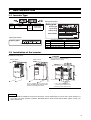
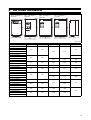
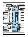
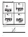
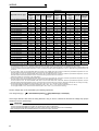
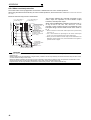
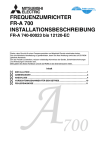
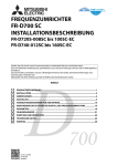
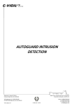
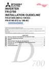
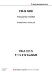
MITSUBISHI ELECTRIC INVERTER FR-A 700 INSTALLATION GUIDELINE FR-A 740-00023 to 12120-EC Thank you for choosing this Mitsubishi Inverter. Please read through this Instruction Manual and the enclosed CD ROM to operate this inverter correctly – The enclosed CD ROM contains the Installation Guideline in additional languages. – Die CD-ROM enthält die deutsche Installationsbeschreibung. – Il CD-ROM incluso contiene la guida di riferimento dell'installazione in lingua italiana. – Le CD-ROM ci-joint contient cette documentation en français. – El CD-ROM incluido contiene la pauta de la instalación en lengua española. – Приложенный CD-ROM содержит инструкцию по инсталяции на дополнительных языках. Do not use this product until you have a full knowledge of the equipment, the safety information and the instructions. Please forward this manual and the CD ROM to the end user. CONTENTS 1 2 3 4 5 INSTALLATION OF THE INVERTER AND INSTRUCTIONS ...................................1 OUTLINE DRAWING .................................................................................................3 WIRING ......................................................................................................................4 PRECAUTIONS FOR USE OF THE INVERTER .....................................................10 TROUBLESHOOTING .............................................................................................11 700 Print Date 12/2006 pdp-dk Manual Number 192716 Revision First edition For Maximum Safety 앫 Mitsubishi transistorized inverters are not designed or manufactured to be used in equipment or systems in situations that can affect or endanger human life. 앫 When considering this product for operation in special applications such as machinery or systems used in passenger transportation, medical, aerospace, atomic power, electric power, or submarine repeating applications, please contact your nearest Mitsubishi sales representative. 앫 Although this product was manufactured under conditions of strict quality control, you are strongly advised to install safety devices to prevent serious accidents when it is used in facilities where breakdowns of the product are likely to cause a serious accident. 앫 Please do not use this product for loads other than three-phase induction motors. 앫 Please check upon receiving of the inverter whether this instruction manual corresponds to the delivered inverter. Compare the specifications on the capacity plate with the specifications given in this manual. This section is specifically about safety matters Do not attempt to install, operate, maintain or inspect the inverter until you have read through this Installation Guideline and appended documents carefully and can use the equipment correctly. Do not use the inverter until you have a full knowledge of the equipment, safety information and instructions. In this Installation Guideline, the safety instruction levels are classified into "WARNING" and "CAUTION". WARNING CAUTION Assumes that incorrect handling may cause hazardous conditions, resulting in death or severe injury. Assumes that incorrect handling may cause hazardous conditions, resulting in medium or slight injury, or may cause physical damage only. CAUTION level may lead to a serious consequence according to conditions. Please follow strictly the instructions Note that even the of both levels because they are important to personnel safety. Electric Shock Prevention WARNING While power is on or when the inverter is running, do not open the front cover. Otherwise you may get an electric shock. Do not run the inverter with the front cover removed. Otherwise, you may access the exposed high-voltage terminals or the charging part of the circuitry and get an electric shock. Even if power is off, do not remove the front cover except for wiring or periodic inspection.You may access the charged inverter circuits and get an electric shock. Before starting wiring or inspection, check to make sure that the operation panel indicator is off, wait for at least 10 minutes after the power supply has been switched off, and check that there are no residual voltage using a tester or the like. The capacitor is charged with high voltage for some time after power off and it is dangerous. This inverter must be earthed (grounded). Earthing (Grounding) must conform to the requirements of national and local safety regulations and electrical codes. (JIS, NEC section 250, IEC 536 class 1 and other applicable standards) Any person who is involved in the wiring or inspection of this equipment should be fully competent to do the work. Always install the inverter before wiring. Otherwise, you may get an electric shock or be injured. Perform setting dial and key operations with dry hands to prevent an electric shock. Otherwise you may get an electric shock. Do not subject the cables to scratches, excessive stress, heavy loads or pinching. Otherwise you may get an electric shock. Do not replace the cooling fan while power is on. It is dangerous to replace the cooling fan while power is on. Do not touch the printed circuit board with wet hands. You may get an electric shock. Fire Prevention CAUTION Mount the inverter to incombustible material. Mounting it to or near combustible material can cause a fire. If the inverter has become faulty, switch off the inverter power. A continuous flow of large current could cause a fire. When using a brake resistor, make up a sequence that will turn off power when an alarm signal is output. Otherwise, the brake resistor may excessively overheat due to damage of the brake transistor and such, causing a fire. Do not connect a resistor directly to the DC terminals P, N. This could cause a fire and destroy the inverter. The surface temperature of braking resistors can far exceed 100°C for brief periods. Make sure that there is adequate protection against accidental contact and a safe distance is maintained to other units and system parts. Injury Prevention CAUTION Apply only the voltage specified in the instruction manual to each terminal. Otherwise, burst, damage, etc. may occur. Ensure that the cables are connected to the correct terminals. Otherwise, burst, damage, etc. may occur. Always make sure that polarity is correct to prevent damage, etc. Otherwise, burst, damage, etc. may occur. While power is on or for some time after power-off, do not touch the inverter as it is hot and you may get burnt. Additional Instructions Also note the following points to prevent an accidental failure, injury, electric shock, etc. Transportation and installation CAUTION When carrying products, use correct lifting gear to prevent injury. Operating condition Do not stack the inverter boxes higher than the number recommended. Ensure that installation position and material can withstand the weight of the inverter. Install according to the information in the instruction manual. Do not install or operate the inverter if it is damaged or has parts missing. This can result in breakdowns. When carrying the inverter, do not hold it by the front cover or setting dial; it may fall off or fail. Do not stand or rest heavy objects on the product. Check the inverter mounting orientation is correct. Prevent other conductive bodies such as screws and metal fragments or other flammable substance such as oil from entering the inverter. As the inverter is a precision instrument, do not drop or subject it to impact. Use the inverter under the following environmental conditions. Otherwise, the inverter may be damaged. Ambient temperature LD (150 %), ND (200 %, initial −10°C to +50°C (non-freezing) setting) and HD (250 %) SLD (120 %) Ambient humidity Storage temperature Atmosphere Altitude Vibration 햲 햳 Temperature applicable for a short time, e.g. in transit. 2.9m/s² or less for the 04320 or more. −10°C to +40 °C (non-freezing) 90% RH or less (non-condensing) −20°C to +65°C 햲 Indoors (free from corrosive gas, flammable gas, oil mist, dust and dirt) Maximum 1000 m above sea level for standard operation. After that derate by 3% for every extra 500m up to 2500m (91%) 5.9m/s2 햳 or less (conforming to JIS C 60068-2-6) Wiring CAUTION Do not install assemblies or components (e. g. power factor correction capacitors) on the inverter output side, which are not approved from Mitsubishi. The direction of rotation of the motor corresponds to the direction of rotation commands (STF/STR) only if the phase sequence (U, V, W) is maintained. Test operation and adjustment CAUTION Before starting operation, confirm and adjust the parameters. A failure to do so may cause some machines to make unexpected motions. Operation WARNING When you have chosen the retry function, stay away from the equipment as it will restart suddenly after an alarm stop. The key is valid only when the appropriate function setting has been made. Prepare an emergency stop switch separately. Make sure that the start signal is off before resetting the inverter alarm. A failure to do so may restart the motor suddenly. The inverter can be started and stopped via the serial port communications link or the field bus. However, please note that depending on the settings of the communications parameters it may not be possible to stop the system via these connections if there is an error in the communications system or the data line. In configurations like this it is thus essential to install additional safety hardware that makes it possible to stop the system in an emergency (e.g. controller inhibit via control signal, external motor contactor etc). Clear and unambiguous warnings about this must be posted on site for the operating and service staff. The load used should be a three-phase induction motor only. Connection of any other electrical equipment to the inverter output may damage the inverter as well as the equipment. Performing pre-excitation (LX signal and X13 signal) under torque control (real sensorless vector control) may start the motor running at a low speed even when the start command (STF or STR) is not input. The motor may run also at a low speed when the speed limit value = 0 with a start command input. Perform pre-excitation after making sure that there will be no problem in safety if the motor runs. Do not modify the equipment. Do not perform parts removal which is not instructed in this manual. Doing so may lead to fault or damage of the inverter. CAUTION The electronic thermal relay function does not guarantee protection of the motor from overheating. Do not use a magnetic contactor on the inverter input for frequent starting/stopping of the inverter. Use a noise filter to reduce the effect of electromagnetic interference and follow the accepted EMC procedures for proper installation of frequency inverters. Otherwise nearby electronic equipment may be affected. Take appropriate measures regarding harmonics. Otherwise this can endanger compensation systems or overload generators. Use a motor designed for inverter operation. (The stress for motor windings is bigger than in line power supply). When parameter clear or all clear is performed, set again the required parameters before starting operations. Each parameter returns to the initial value. The inverter can be easily set for high-speed operation. Before changing its setting, fully examine the performances of the motor and machine. The DC braking function of the frequency inverter is not designed to continuously hold a load. Use an electro-mechanical holding brake on the motor for this purpose. Before running an inverter which had been stored for a long period, always perform inspection and test operation. For prevention of damage due to static electricity, touch nearby metal before touching this product to eliminate static electricity from your body. Emergency stop CAUTION Provide a safety backup such as an emergency brake which will prevent the machine and equipment from hazardous conditions if the inverter fails. When the breaker on the inverter primary side trips, check for the wiring fault (short circuit), damage to internal parts of the inverter, etc. Identify the cause of the trip, then remove the cause and power on the breaker. When the protective function is activated (i. e. the frequency inverter switches off with an error message), take the corresponding corrective action as described in the inverter manual, then reset the inverter, and resume operation. Maintenance, inspection and parts replacement CAUTION Do not carry out a megger (insulation resistance) test on the control circuit of the inverter. Disposing of the inverter CAUTION Treat as industrial waste. General instructions Many of the diagrams and drawings in instruction manuals show the inverter without a cover, or partially open. Never run the inverter in this status. Always replace the cover and follow instruction manuals when operating the inverter. 1 INSTALLATION 1.1 Inverter Type Rating plate example Symbol Voltage Class Symbol Type number A740 Three-phase 400V class 00023 to 12120 Displays the rated current Rating plate Inverter type Input rating Output rating Serial number Capacity plate example Capacity plate Inverter type Serial number Overload current rating Ambient temperature SLD 110% 60s, 120% 3s 40°C LD 120% 60s, 150% 3s 50°C ND 150% 60s, 200% 3s 50°C HD 200% 60s, 250% 3s 50°C 1.2 Installation of the inverter Installation on the panel 00023 to 00620 CAUTION 00770 to 12120 When encasing multiple inverters, install them in parallel and leave clearance as a cooling measure. Install the inverter vertically. 10 cm or more *2 vertic 10 cm or more *2 Fix six positions for the FR-A 74004320 to 08660 and fix eight positions for the R-A 740-09620 to 12120. 5 cm or more *1 *1 1 cm or more for 00126 or less 10 cm or more for 02160 or more *2 20 cm or more for 02160 or more . Note The internal filter is suitable for the second environment, a motor cable length of up to 5m and a carrier frequency of up to 2kHz. For other operation conditions, Mitsubishi Electric offers several optional filters. Please contact your sales representive. 1 INSTALLATION 1.3 General Precaution The bus capacitor discharge time is 10 minutes. Before starting wiring or inspection, switch power off, wait for more than 10 minutes, and check for residual voltage between terminal P/+ and N/− with a meter etc., to avoid a hazard of electrical shock. 1.4 Environment Before installation, check that the environment meets following specifications. -10°C to +50°C (non-freezing) for selected overload capability 150 %, 200 % (initial setting) or 250 % Ambient temperature Ambient humidity Storage temperature Ambience Altitude, vibration 햲 -10°C to +40°C (non-freezing) for selected overload capability 120 % −20°C to +65°C Indoors (No corrosive and flammable gases, oil mist, dust and dirt) Below 1000m, 5.9m/s2 햲 or less 2.9m/s² or less for the 04320 or more. CAUTION Measurement position 5 cm Measurement position 90% RH or less (non-condensing) Install the inverter on a strong surface securely and vertically with bolts. Leave enough clearances and take cooling measures. Avoid places where the inverter is subjected to direct sunlight, high temperature and high humidity. Install the inverter on a non-combustible surface. 2 Inverter 5 cm 5 cm 2 OUTLINE DRAWING FR-A 740-00023 to 00620-EC FR-A 740-00770 to 03610-EC FR-A 740-09620 to 12120-EC FR-A 740-04320 to 08660-EC (Unit: mm) Inverter Type W W1 150 125 H H1 260 245 D FR-A 740-00023-EC FR-A 740-00038-EC FR-A 740-00052-EC FR-A 740-00083-EC 140 FR-A 740-00126-EC FR-A 740-00170-EC FR-A 740-00250-EC FR-A 740-00310-EC 170 220 195 FR-A 740-00380-EC FR-A 740-00470-EC FR-A 740-00620-EC FR-A 740-00770-EC 300 285 190 250 230 400 380 190 325 270 550 530 195 435 380 550 525 250 620 595 300 465 400 740 715 360 FR-A 740-00930-EC FR-A 740-01160-EC FR-A 740-01800-EC FR-A 740-02160-EC FR-A 740-02600-EC FR-A 740-03250-EC FR-A 740-03610-EC FR-A 740-04320-EC FR-A 740-04810-EC 498 200 680 300 790 315 1330 1300 995 300 1580 1550 FR-A 740-05470-EC FR-A 740-06100-EC 985 1010 380 984 FR-A 740-06830-EC FR-A 740-07700-EC FR-A 740-08660-EC FR-A 740-09620-EC FR-A 740-10940-EC 440 FR-A 740-12120-EC 3 3 WIRING Source logic Main circuit terminal Control circuit terminal *1. DC reactor (FR-HEL) Remove the jumper for the 01160 or less if a DC reactor is connected. The DC reactor supplied with the 01800 or more should be connected to these terminals. Brake unit (Option) Earth Jumper *7 The CN8 connector is provided with the 1800 or more. *8 Brake resistor (FR-ABR) Remove the jumper across terminal PX–PR when connecting a brake resistor (00023 to 00620). Terminal PR is provided for the 00023 to 00620. Install a thermal relay to prevent an overheat and burnout of the brake resistor. Jumper 3-phase AC power supply Jumper *2 To supply power to the control circuit separately, remove the jumper across R/L1–R1/L11 and S/L2–S1/L21. Connect the power to the terminals R1/L11 and S1/L21 then. *2 Earth M 3~ Connector for with/without internal EMC filter Main circuit Control circuit Control input signals (No voltage input allowed) Terminal functions vary with the input terminal assignment. (Pr. 178 to Pr. 189) Motor Relay output Forward rotation start Reverse rotation start Start self-holding selection Relay output 1 (Alarm output) Terminal functions vary with the output terminal assignment. (Pr. 195, Pr. 196) High speed Multi-speed selection Relay output 2 Medium speed Low speed *3 JOG terminal can be used as pulse train input. Use Pr. 291 to select JOG/Pulse. Open-Collector output Jog mode Running Second function selection *4. AU terminal can be used as PTC input terminal. Up to frequency Instantaneous power failure Output stop Terminal functions vary with the output terminal assignment. (Pr. 190 bis Pr. 194) Overload RESET Terminal 4 input selection (current input selection) Frequency detection Open collector output common Sink/source common Selection of automatic restart after instantaneous power failure Contact input common (Sink*) 24VDC power supply/ max. 100mA load current Contact input common(Source*) *(Common for external power supply transistor) *5 Voltage/current input switch PU connector Frequency setting signal (Analog) USB connector Analog current output (0 to 20 mA DC) 0–5 V DC Frequency setting potentiometer 1 kΩ,1/2 W, 0 to 10 V DC 4 to 20 mA DC Analog signal output (0 to 10 V DC) *5 The input area can be set via parameters. The setting within Auxiliary the frame is pre-set at the input factory. (Pr. 73, Pr. 267). Set the voltage/current input switch in the OFF position to Terminal 4 select voltage input (0 to 5 V input (Current or 0 to 10 V) and in the ON input) position to select current input (0/4 to 20 mA). 0– ±10 V DC 0 to ±5 V DC RS485 terminals 4–20 mA DC Data transmission 0 to 5 V DC 0 to 10 V DC Connector for plug-in option Data reception Option connector 1 Option connector 2 *6 It is recommended to use a 1 kΩ, 2 W potentiometer when the frequency setting signal is changed frequently. Option connector 3 Terminating resistor (Permissible load current 100mA) CAUTION To prevent a malfunction due to noise, keep the signal cables more than 10cm away from the power cables. After wiring, wire offcuts must not be left in the inverter. Wire offcuts can cause an alarm, failure or malfunction. Always keep the inverter clean. When drilling mounting holes in a control box etc., take care not to allow chips and other foreign matter to enter the inverter. Set the voltage/current input switch in the correct position. An incorrect setting may cause a fault, failure or malfunction. 4 WIRING 3.1 Main circuit terminal 3.1.1 Terminal layout and wiring FR-A 740-00023, 00038, 00052, 00083, 00126-EC FR-A 740-00170, 00250-EC Jumper Screw size (M4) Charge lamp Jumper Jumper Jumper Screw size (M4) L1 L2 L3 M 3~ Power supply Motor Charge lamp Screw size (M4) L1 L2 L3 M 3~ Motor Power supply Screw size (M4) FR-A 740-00310, 00380-EC FR-A 740-00470, 00620-EC Screw size (M4) Screw size (M4) Charge lamp Jumper Screw size (M6) Jumper Charge lamp Jumper Screw size (M5) L1 L2 L3 Power supply L1 L2 L3 Power supply M 3~ Motor Jumper M 3~ Screw size (M6) Motor Screw size (M5) FR-A 740-00770, 00930, 01160-EC FR-A 740-01800-EC Screw size (M4) Charge lamp Screw size (M4) Jumper Charge lamp Jumper Screw size (00770: M6) 00930A, 01160A: M8) Screw size (M8) Jumper L1 L2 L3 Power supply Screw size (00770: M6 00930, 01160: M8) Screw size (M8) Screw size (M10) L1 L2 L3 M 3~ Motor Power supply DC reactor M 3~ Motor Screw size (M8) 5 WIRING FR-A 740-02160, 02600-EC FR-A 740-03250, 03610-EC Screw size M4 Charge lamp Jumper Screw size (M4) Charge lamp Screw size M10 Jumper Screw size M10 Schrauben (M10) Screw size (M10) L1 L2 L3 Power supply L1 L2 L3 M 3~ Power supply Motor DC reactor Screw size M12 (for option) DC reactor M 3~ Motor Screw size M10 FR-A 740-04320, 04810-EC FR-A 740-05470 bis 12120-EC Screw size M4 Screw size M4 Charge lamp Charge lamp Jumper Jumper Screw size M12 Schrauben M12 Screw size (M10) L1 L2 L3 Power supply Screw size M12 (for option) DC reactor M 3~ Motor L1 L2 L3 Power supply DC reactor M 3~ Motor Screw size M10 CAUTION The power supply cables must be connected to R/L1, S/L2, T/L3. Never connect the power cable to the U, V, W, of the inverter. Doing so will damaged the inverter. (Phase sequence needs not to be matched.) Connect the motor to U, V, W. At this time turning on the forward rotation switch (signal) rotates the motor in the clockwise direction when viewed on the motor shaft. When wiring the inverter main circuit conductor of the FR-A740-0432005470 or more, tighten a nut from the right side of the conductor. When wiring two wires, place wires on both sides of the conductor. (Refer to the drawing below.) For wiring, use bolts (nuts) provided with the inverter. 6 WIRING 3.2 Wiring fundamentals 3.2.1 Cable size Select the recommended cable size to ensure that a voltage drop will be 2% max. If the wiring distance is long between the inverter and motor, a main circuit cable voltage drop will cause the motor torque to decrease especially at the output of a low frequency. The following table indicates a selection example for the wiring length of 20m. 400V class (when input power supply is 440V) Applicable Inverter Type FR-A 740-00023–00126-EC FR-A 740-00170-EC FR-A 740-00250-EC FR-A 740-00310-EC FR-A 740-00380-EC FR-A 740-00470-EC FR-A 740-00620-EC FR-A 740-00770-EC FR-A 740-00930-EC FR-A 740-01160-EC FR-A 740-01800-EC FR-A 740-02160-EC FR-A 740-02600-EC FR-A 740-03250-EC FR-A 740-03610-EC FR-A 740-04320-EC FR-A 740-04810-EC FR-A 740-05470-EC FR-A 740-06100-EC FR-A 740-06830-EC FR-A 740-07700-EC FR-A 740-08660-EC FR-A 740-09620-EC FR-A 740-10940-EC FR-A 740-12120-EC Terminal Screw Size *4 Tightening Torque [Nm] M4 M4 M4 M5 M5 M6 M6 M6 M8 M8 M8 M10 M10 M10/M12 M10/M12 M12/M10 M12/M10 M12/M10 M12/M10 M12/M10 M12/M10 M12/M10 M12/M10 M12/M10 M12/M10 1.5 1.5 1.5 2.5 2.5 4.4 4.4 4.4 7.8 7.8 7.8 14.7 14.7 14.7 14.7 24.5 24.5 24.5 24.5 24.5 24.5 24.5 24.5 24.5 24.5 Crimping Terminal R/L1, S/L2, T/L3 U, V, W 2-4 2-4 2-4 2-4 5.5-4 5.5-4 5.5-5 5.5-5 8-5 8-5 14-6 8-6 14-6 14-6 22-6 22-6 22-8 22-8 38-8 38-8 60-8 60-8 60-10 60-10 60-10 60-10 80-10 80-10 100-10 100-10 150-12 150-12 150-12 150-12 100-12 100-12 100-12 100-12 150-12 150-12 150-12 150-12 C2-200 C2-200 C2-200 C2-200 C2-250 C2-250 C2-200 C2-250 7 WIRING Cable Sizes HIV, etc. [mm2] *1 Applicable Inverter Type FR-A 740-00023–00126-EC FR-A 740-00170-EC FR-A 740-00250-EC FR-A 740-00310-EC FR-A 740-00380-EC FR-A 740-00470-EC FR-A 740-00620-EC FR-A 740-00770-EC FR-A 740-00930-EC FR-A 740-01160-EC FR-A 740-01800-EC FR-A 740-02160-EC FR-A 740-02600-EC FR-A 740-03250-EC FR-A 740-03610-EC FR-A 740-04320-EC FR-A 740-04810-EC FR-A 740-05470-EC FR-A 740-06100-EC FR-A 740-06830-EC FR-A 740-07700-EC FR-A 740-08660-EC FR-A 740-09620-EC FR-A 740-10940-EC FR-A 740-12120-EC R/L1, S/L2, T/L3 2 2 3.5 5.5 8 14 14 22 22 38 60 60 60 80 100 125 150 2 x 100 2 x 100 2 x 125 2 x 150 2 x 200 2 x 200 2 x 250 3 x 200 U, V, W P/+, P1 2 2 3.5 5.5 8 8 14 22 22 38 60 60 60 80 100 150 150 2 x 100 2 x 100 2 x 125 2 x 150 2 x 200 2 x 200 2 x 250 2 x 250 2 3.5 3.5 5.5 8 14 22 22 22 38 60 60 80 80 100 150 150 2 x 100 2 x 125 2 x 125 2 x 150 2 x 200 2 x 200 2 x 250 3 x 200 Earth Cable Gauge 2 3.5 3.5 8 8 14 14 14 14 22 22 38 38 38 38 38 38 60 60 60 100 100 100 100 2 x 100 AWG *2 R/L1, S/L2, U, V, W T/L3 14 14 12 14 12 12 10 10 8 8 6 8 6 6 4 4 4 4 1 2 1/0 1/0 1/0 1/0 3/0 3/0 3/0 3/0 4/0 4/0 250 250 300 300 2 x 4/0 2 x 4/0 2 x 4/0 2 x 4/0 2 x 250 2 x 250 2 x 300 2 x 300 2 x 350 2 x 350 2 x 400 2 x 400 2 x 500 2 x 500 2 x 500 2 x 500 PVC, etc. [mm2] *3 R/L1, S/L2, T/L3 2.5 2.5 4 6 10 16 16 25 25 50 50 50 50 70 95 120 150 2 x 95 2 x 95 2 x 120 2 x 150 2 x 185 2 x 185 2 x 240 2 x 240 U, V, W Earth Cable Gauge 2.5 2.5 4 6 10 10 16 25 25 50 50 50 50 70 95 120 150 2 x 95 2 x 95 2 x 120 2 x 150 2 x 185 2 x 185 2 x 240 2 x 240 2.5 4 4 10 10 16 16 16 16 25 25 25 25 35 50 70 95 95 95 120 150 2 x 95 2 x 95 2 x 120 2 x 120 *1 For the 01800 or less, the recommended cable size is that of the HIV cable (600V class 2 vinyl-insulated cable) with continuous maximum permissible temperature of 75°C. Assumes that the ambient temperature is 50°C or less and the wiring distance is 20m or less. For the 02160 or more, the recommended cable size is that of LMFC (heat resistant flexible cross-linked polyethylene insulated cable) with continuous maximum permissible temperature of 90°C. Assumes that the ambient temperature is 50°C or less and wiring is performed in an enclosure. *2 For the 01160 or less, the recommended cable size is that of the THHW cable with continuous maximum permissible temperature of 75°C. Assumes that the ambient temperature is 40°C or less and the wiring distance is 20m or less. For the 01800 or more, the recommended cable size is that of THHN cable with continuous maximum permissible temperature of 90°C. Assumes that the ambient temperature is 40°C or less and wiring is performed in an enclosure. (Selection example for use mainly in the Unite States.) *3 For the 01160 or less, the recommended cable size is that of the PVC cable with continuous maximum permissible temperature of 70°C. Assumes that the ambient temperature is 40°C or less and the wiring distance is 20m or less. For the 01800 or more, the recommended cable size is that of XLPE cable with continuous maximum permissible temperature of 90°C. Assumes that the ambient temperature is 40°C or less and wiring is performed in an enclosure. (Selection example for use mainly in Europe.) *4 The terminal screw size indicates the terminal size for R/L1, S/L2, T/L3, U, V, W, and a screw for earthing. For the types 03250 and 03610, screw sizes are different (R/L1, S/L2, T/L3, U, V, W, screw for earthing: M10 / P/+: M12). For the types 04320 or more, screw sizes are different (R/L1, S/L2, T/L3, U, V, W / screw for earthing. The line voltage drop can be calculated by the following expression: 3 × wire resistance [ m Ω/′ m ] × wiring distance [m] × current [A]Line voltage drop [V] = ---------------------------------------------------------------------------------------------------------------------------------------------------------------------------------1000 Use a larger diameter cable when the wiring distance is long or when it is desired to decrease the voltage drop (torque reduction) in the low speed range. CAUTION Tighten the terminal screw to the specified torque. A screw that has been tighten too loosely can cause a short circuit or malfunction. A screw that has been tighten too tightly can cause a short circuit or malfunction due to the unit breakage. Use crimping terminals with insulation sleeve to wire the power supply and motor. 8 WIRING 3.2.2 Maximum permissible motor wiring length The maximum permissible length of the motor cables depends on the capacity of the inverter and the selected carrier frequency. (The wiring lenght should be 100 m maximum with vector control). The lengths in the following table are for unshielded cables. When shielded cables are use divide the values listed in the table by 2. Note that the values are for the total wiring length – if you connect more than one motor in parallel you must add the lengths of the individual motor cables. Setting of Pr. 72 PWM Frequency selection (carrier frequency) 00023 00038 2 (2 kHz) or less 300 m 500 m 500 m 3 (3 kHz), 4 (4 kHz) 200 m 300 m 500 m 5 (5 kHz) to 9 (9 kHz) 100 m 10 (10 kHz) or more 50 m ≥ 00052 Note For the 01800 or more, the setting range of Pr. 72 PWM frequency selection is "0 to 6". Note that the motor windings in three-phase AC motors are subject to far more stress when operated via frequency inverters than with mains operation. The motor must have been approved by the manufacturer for operation on a frequency inverter. CAUTION Especially for long-distance wiring (particularly when employing shielded motor cables), the inverter may be affected by a charging current caused by the stray capacitances of the wiring, leading to a malfunction of the overcurrent protective function or fast response current limit function or a malfunction or fault of the equipment connected on the inverter output side. When the fast-response current limit function malfunctions, make the function invalid. (For Pr.156 Stall prevention operation selection, refer to the Instruction Manual (applied).) For details of Pr. 72 PWM frequency selection, refer to the Instruction Manual (applied). (When using an option sine wave filter (MT-BSL/BSC) for the 02160 or more, set parameter 72 to „25“ (2.5 kHz). 3.2.3 Cable size of the control circuit power supply (terminals R1/L11, S1/L21) Terminal srew size: M4 Cable size: 0.75mm2 to2 mm2 Tightening torque: 1.5Nm 9 3.3 Control circuit terminals 3.3.1 Terminal layout CA A1 B1 C1 PC AM 10E 10 A2 B2 2 C2 5 RL 4 RM RH 1 RT SD PC AU STOP RES STF STR PC SE RUN SU IPF OL FU MRS JOG CS 3.3.2 Instructions for wiring of the control circuit terminal Terminals PC, 5, and SE are all common terminals (0V) for I/O signals and are isolated from each other. Avoid connecting the terminal PC and 5 and the terminal SE and 5 (ground). Terminal PC is a common terminal for the contact input terminals (STF, STR, STOP, RH, RM, RL, JOG, RT, MRS, RES,AU, CS). Use shielded or twisted cables for connection to the control circuit terminals and run them away from the main and power circuits (including the 230V relay sequence circuit).. Use two or more parallel micro-signal contacts or twin contacts to prevent a contact faults when using contact inputs since the control circuit input signals are microcurrents. Micro signal contacts Zwillingskontakte Do not apply a voltage to the contact input terminals (e.g. STF) of the control circuit. Always apply a voltage to the alarm output terminals (A, B, C) via a relay coil, lamp, etc. It is recommended to use the cables of 0.75mm2 gauge for connection to the control circuit terminals. If the cable gauge used is 1.25mm2 or more, the front cover may be lifted when there are many cables running or the cables are run improperly, resulting in an operation panel contact fault. The wiring length should be 30m maximum. The level of the control signals can be switched over between positive (SOURCE) and negative (SINK) logic. The input signals are set to source logic when shipped from the factory. To change the control logic, the jumper connector on the control circuit terminal block must bemoved to the other position. 10 4 PRECAUTIONS FOR USE OF THE INVERTER The FR-A700 series is a highly reliable product, but incorrect peripheral circuit making or operation/handling method may shorten the product life or damage the product. Before starting operation, always recheck the following items. 앫 Use crimping terminals with insulation sleeve to wire the power supply and motor. 앫 Application of power to the output terminals (U, V, W) of the inverter will damage the inverter. Never perform such wiring. 앫 After wiring, wire offcuts must not be left in the inverter. Wire offcuts can cause an alarm, failure or malfunction. Always keep the inverter clean. When drilling mounting holes in a control box etc., take care not to allow chips and other foreign matter to enter the inverter. 앫 Use cables of the size to make a voltage drop 2% maximum. If the wiring distance is long between the inverter and motor, a main circuit cable voltage drop will cause the motor torque to decrease especially at the output of a low frequency. Refer to page 7 for the recommended cable size. 앫 The overall wiring length should be 500m maximum. (For vector control the wiring lenght should be 100m maximum.) Especially for long distance wiring, the fast-response current limit function may be reduced or the equipment connected to the inverter output side may malfunction or become faulty under the influence of a charging current due to the stray capacity of the wiring. Therefore, note the overall wiring length. (Refer to page 7) 앫 Electromagnetic Compatibility Operation of the frequency inverter can cause electromagnetic interference in the input and output that can be propagated by cable (via the power input lines), by wireless radiation to nearby equipment (e.g. AM radios) or via data and signal lines. Activate the integrated EMC filter (and an additional optional filter if present) to reduce air propagated interference on the input side of the inverter. Use AC or DC reactors to reduce line propagated noise (harmonics). Use shielded motor power lines to reduce output noise. 앫 Do not install a power factor correction capacitor, varistor or arrester on the inverter output side. This will cause the inverter to trip or the capacitor, varistor, or arrester to be damaged. If any of the above devices is installed, immediately remove it. 앫 Before starting wiring or other work after the inverter is operated, wait for at least 10 minutes after the power supply has been switched off, and check that there are no residual voltage using a tester or the like. The capacitor is charged with high voltage for some time after power off and it is dangerous. 앫 A short circuit or earth fault on the inverter output side may damage the inverter modules. – Fully check the insulation resistance of the circuit prior to inverter operation since repeated short circuits caused by peripheral circuit inadequacy or an earth fault caused by wiring inadequacy or reduced motor insulation resistance may damage the inverter modules. – Fully check the to-earth insulation and inter-phase insulation of the inverter output side before power-on. Especially for an old motor or use in hostile atmosphere, securely check the motor insulation resistance etc. 앫 Do not use the inverter input side magnetic contactor to start/stop the inverter. Always use the start signal (ON/OFF of STF and STR signals) to start/stop the inverter. 앫 Across P/+ and PR reminals, connect only an external regenerative brake discharge resistor. Do not connect a mechanical brake. 앫 Do not apply a voltage higher than the permissible voltage to the inverter I/O signal circuits. Contact to the inverter I/O signal circuits or opposite polarity may damage the I/O devices. Especially check the wiring to prevent the speed setting potentiometer from being connected incorrectly to short terminals 10E (10, respectively) -5. 앫 Provide electrical and mechanical interlocks for MC1 and MC2 Interlock Power which are used for commercial power supply-inverter switch-over. supply When the wiring is incorrect or if there is a commercial power M 3~ supply-inverter switch-over circuit as shown below, the inverter will be damaged by leakage current from the power supply due to arcs Undesirable Current generated at the time of switch-over or chattering caused by a Inverter sequence error. (Commercial operation can not be performed with the vector dedicated motor (SF-V5RU, SF-THY).) 앫 If the machine must not be restarted when power is restored after a power failure, provide a magnetic contactor in the inverter's input side and also make up a sequence which will not switch on the start signal. If the start signal (start switch) remains on after a power failure, the inverter will automatically restart as soon as the power is restored. 앫 Instructions for overload operation When performing operation of frequent start/stop of the inverter, increase/decrease in the temperature of the transistor element of the inverter may repeat due to a continuous flow of large current, shortening the life from thermal fatigue. Since thermal fatigue is related to the amount of current, the life can be increased by reducing bound current, starting current, etc. Decreasing current may increase the life. However, decreasing current will result in insufficient torque and the inverter may not start. Therefore, increase the inverter capacity to have enough allowance for current. 앫 Make sure that the specifications and rating match the system requirements. 앫 For vector control a motor with encoder is necessary. Connect the encoder directly to the backlash-free motor shaft. For real sensorless vector control an encoder is not necessary. 11 TROUBLESHOOTING 5 TROUBLESHOOTING When an alarm occurs in the inverter, the protective function is activated bringing the inverter to an alarm stop and the PU display automatically changes to any of the following error (alarm) indications. If your fault does not correspond to any of the following errors or if you have any other problem, please contact your sales representative. Retention of alarm output signal...... When the magnetic contactor (MC) provided on the input side of the inverter is opened at the activation of the protective function, the inverter's control power will be lost and the alarm output will not be held. Alarm display ................................... When the protective function is activated, the operation panel display automatically switches to the above indication. Resetting method ............................ When a protective function of the inverter is activated, the power output of the inverter is blocked (motor is coasting). The inverter cannot start up again unless an automatic restart has been configured or the inverter is reset. Please observe carefully the warnings contained below in the configuration of an automatic restart or the execution of a reset. If protective functions were activated (i. e. the inverter switched off with an error message) follow the instructions for error correction provided in the manual for the inverter. Especially in the case of short circuits or earth contacts in the inverter output and mains overvoltages the cause of the fault must be determined prior to switching on again as a recurrence of such faults at short intervals can lead to premature aging of components or even the complete breakdown of the device. After the cause of the fault has been found and corrected the inverter can be reset and operations continue. Inverter alarm displays are roughly divided as below. • Error Message A message regarding operational fault and setting fault by the operation panel (FR-DU07) and parameter unit (FR-PU04 /FRPU07) is displayed. The inverter does not shut off output. • Warnings The inverter does not shut off output even when a warning is displayed. However, failure to take appropriate measures will lead to a major fault. • Minor fault The inverter does not shut off output.You can also output a minor fault signal by making parameter setting. • Major fault When the protective function is activated, the inverter output is shut off and an alarm is output. 5.1 Reset method of protective function Resetting the inverter The inverter can be reset by performing any of the following operations. Note that the internal thermal integrated value of the electronic thermal relay function and the number of retries are cleared (erased) by resetting the inverter. Recover about 1s after reset is cancelled. Three different methods can be used to reset an inverter. • Using the operation panel, press the STOP/RESET key to reset the inverter. (Enabled only when the inverter protective function is activated (major fault)).. • Switch power off once, then switch it on again. ON OFF • Turn on the reset signal (RES) for more than 0.1s. (If the RES signal is kept on, "Err." appears (flickers) to indicate that the inverter is in a reset status.) Inverter RESET RES PC 12 TROUBLESHOOTING 5.2 List of alarm display Warnings Error messages Operation Panel Indication bis to Meaning Operation Panel Indication E--- Alarm history E.GF HOLD Operation panel lock E.LF Output phase failure protection E.OHT External thermal relay operation Er1 bis 4 Parameter write error E.PTC* PTC-Thermistor-Auslösung bis to rE1 bis 4 Copy operation error Err. Error OL Stall Prevention (overcurrent) oL Stall prevention (overvoltage) RB Regenerative brake prealarm TH Electronic thermal relay function prealarm PS PU Stop MT Maintenance signal output CP Parameter copy SL Speed limit indication (Output during speed limit) to FN Fan fault / Major Fault Minor fault / Major fault Meaning Output side earth (ground) fault overcurrent protection E.OPT Option alarm E.OP3 Communication option alarm E. 1 bis E. 3 Option alarm (e. g. connection or contact fault) E.PE Parameter storage device alarm E.PUE PU disconnection E.RET Retry count excess E.PE2* Parameter storage device alarm E. 6 / E. 7 / E.CPU CPU error E.CTE Operation panel power supply short circuit RS-485 terminal power supply short circuit E.P24 24VDC power output short circuit E.OC1 Overcurrent shut-off during acceleration E.OC2 Overcurrent cut-off during constant speed E.OC3 Overcurrent shutoff during deceleration or stop E.OV1 Regenerative overvoltage shut-off during acceleration E.OV2 Regenerative overvoltage shut-off during constant speed E.OV3 Regenerative overvoltage shut-off during deceleration or stop E.OSD Speed deviation excess detection E.THT Inverter overload shutoff (electronic thermal relay function) E.ECT Open cable detection E.THM Motor overload shutoff (electronic thermal relay function) E.OD Excessive position error E.FIN Fin overheat E.IPF Instantaneous power failure protection E.MB1 bis E.MB7 Brake sequence error E.UVT Brake transistor alarm detection/ Internal circuit error E.EP Encoder phase error E.ILF* Input phase failure E.BE Brake transistor alarm detection E.OLT Stall Prevention Output current detection value E.CDO* exceeded E.IOH* Inrush resistor overheat E.SER* Communication error (inverter) bis to E.AIE* Analog input error E.OS Overspeed occurence E.USB* USB communication error E.11 Opposite rotation deceleration error E.13 Internal circuit error * If an E.ILF, E.PTC, E.PE2, E.CDO, E.IOH, E.SER, E.AIE or E.USB error occurs when using the FR-PU04, "Fault 14" is displayed on the FR-PU04. 13 TROUBLESHOOTING 14 A APPENDIX A.1 Instructions for Compliance with the European Directives A.1.1 EMC Directive We have self-confirmed our inverters as products compliant to the EMC Directive (second environment of conforming standard EN61800-3) and placed the CE mark on the inverters. Remarks First environment Environment including residential buildings. Includes buildings directly connected without a transformer to the low voltage power supply network which supplies power to residential buildings. Second environment Environment including all buildings except buildings directly connected without a transformer to the low voltage power supply network which supplies power to residential buildings. A.1.2 Notes Install the inverter (and if necessary optional radio interference suppression filters) and perform wiring according to the following instructions. The FR-A 700 EC inverters are equipped with a built-in EMC filter. Set the EMC filter valid (initial setting). Connect the inverter to an earthed power supply. Install a motor and a control cable written in the EMC Installation Manual (BCN-A21041-204) according to the instruction. The maximum cable length (shielded cable) between the frequency inverter and motor required to maintain the limiting values of the second environment is 5m when using the internal radio interference suppression filter. Make sure that the frequency inverter, if required (optional external) radio interference suppression filters and the motor are installed in compliance with generally recognised EMC installation regulations. It is not permitted to start up the device unless the EMC guidelines are complied with. A.1.3 Low Voltage Directive We have self-confirmed our inverters as products compliant to the Low Voltage Directive (Conforming standard EN 50178) and placed the CE mark on the inverters. Outline of instructions Do not use a residual current operated protective device (RCD) as an electric shock protector without connecting the equipment to the earth. Connect the equipment to the earth securely. Wire the earth terminal independently. (Do not connect two or more cables to one terminal.) Use the cable sizes on page 7 under the following conditions. – Ambient temperature: 40°C maximum – Wire installation: With conduits for 400V, 00380 or less On wall without ducts or conduits for 400V, 00470 or more If conditions are different from above, select appropriate wire according to EN60204 Appendix C TABLE 5. Use a tinned (plating should not include zinc) crimping terminal to connect the earth cable. When tightening the screw, be careful not to damage the threads. For use as a product compliant with the Low Voltage Directive, use PVC cable whose size is indicated on page 7. Use the moulded case circuit breaker and magnetic contactor which conform to the EN or IEC Standard. When using an earth leakage current breaker, use a residual current operated protective device (RCD) of type B (breaker which can detect both AC and DC.) If not, provide double or reinforced insulation between the inverter and other equipment, or put a transformer between the main power and inverter. Use the residual current operated protective device (RCD) of type B (breaker which can detect both AC and DC). However, be aware that also AC/DC sensitive earth leakage circuit breakers can be activated when turning the main power on and off and that this behaviour can be improved through the use of AC/DC sensitive earth leakage circuit breakers with adapted triggering curve designed for the inverter. If not, provide double or reinforced insulation between the inverter and other equipment, or put a transformer between the main power supply and inverter. 15 APPENDIX Use the inverter under the conditions of overvoltage category II (usable regardless of the earth condition of the power supply), overvoltage category III (usable with the earthed-neutral system power supply) and pollution degree 2 or lower specified in IEC664. – To use the inverter FR-A 740 EC of 00930 or more (IP00) under the conditions of pollution degree 2, install it in the enclosure of IP 2X or higher. – To use the inverter FR-A 740 EC under the conditions of pollution degree 3, install it in the enclosure of IP54 or higher. – To use the inverter FR-A 740 EC of 00770 or less (IP20) outside of an enclosure in the environment of pollution degree 2, fix a fan cover with fan cover fixing screws enclosed. Fan cover fixing screws Fan cover fixing screws Fan cover fixing screws Fan cover Fan cover Fan cover Fan Fan 00083, 00126 Fan 00170 bis 00380 00470, 00620 On the input and output of the inverter, use cables of the type and size set forth in EN60204 Appendix C. The operating capacity of the relay outputs (terminal symbols A1, B1, C1, A2, B2, C2) should be 30VDC, 0.3A. (Relay outputs are basically isolated from the inverter internal circuit.) Control circuit terminals on page 4 are safely isolated from the main circuit. Environment During Operation In Storage During Transportation −20°C to +65°C −20°C to +65°C -10°C to +50°C (non-freezing) for selected overload capability 150 %, 200 % (initial setting) or 250 % Ambient temperature -10°C to +40°C (non-freezing) for selected overload capability 120 % The maximum temperature depends on the setting of the parameter 570. Ambient humidity 90% RH or less 90% RH or less 90% RH or less Maximum altitude 1000m 1000m 10000m A.1.4 Machine directive The frequency inverter itself is not a machine in the spirit of the EU machine directive. The start up of the frequency inverter in a machine is prohibited so long until it has been confirmed that the entire machine complies with the provisions of Directive 89/392/EWG (machine directive). 16 APPENDIX A.2 Instructions for UL and cUL (UL 508C, CSA C22.2 Nr.14) A.2.1 Installation The inverter FR-A 740 EC is UL-listed as a product for use in an enclosure. Design an enclosure so that the inverter ambient temperature, humidity and atmosphere satisfy the specifications. (Refer to page 2) Wiring protection For installation in the United States, branch circuit protection must be provided in accordance with the National Electrical Code and any applicable provincial codes. For installation in Canada, branch circuit protection must be provided in accordance with the Canada Electrical Code and any applicable provincial codes. Provide the appropriate UL Listed Class RK5 oder class T fuses that are suitable for branch circuit protection in accordance with the table below. FR-A 740--EC 00023 00038 00052 00083 00126 00170 00250 00310 00380 00470 00620 00770 00930 01160 01800 Rated voltage [V] Rated current [A] 480V or more Without power factor improving reactor 6 10 15 20 30 40 70 80 90 110 150 175 200 250 300 With power factor improving reactor 6 10 10 15 25 35 60 70 90 100 125 150 175 200 250 FR-A 740--EC 02160 02600 03250 03610 04320 04810 05470 06100 06830 07700 08660 09620 10940 12120 Rated voltage [V] Rated current [A] Without power factor improving reactor With power factor improving reactor 500V or more — — — — — — — — 300 350 400 500 600 700 800 900 — — — — — — 1000 1100 1200 1350 1500 1800 A.2.2 Wiring of the power supply and motor For wiring the input (R/L1, S/L2, T/L3) and output (U, V, W) terminals of the inverter, use the UL-listed copper wires (rated at 75°C) and round crimping terminals. Crimp the crimping terminals with the crimping tool recommended by the terminal maker. A.2.3 Short circuit ratings 01800 or less Suitable for use in a circuit capable of delivering not more than 100kA rms symmetrical amperes, 528V maximum. 02160 or more Suitable for use in a circuit capable of delivering not more than 100kA rms symmetrical amperes, 550V maximum. 17 APPENDIX A.2.4 Motor overload protection The inverter FR-A 740 is equipped with an internal UL certified electronic motor overload protection. When using the electronic thermal relay as motor overload protection, set the rated motor current to Pr.9 Electronic thermal O/L relay. Electronic thermal relay function characteristic Operation time [min] Pr. 9 = 100% setting of inverter rating *1, 2 or more *3 or more *3 Operation time [s] [s] unit display in this region [min] unit display in this region Pr. 9 = 50% setting of inverter rating *1, 2 Operation: left side of characteristic curve Non-Operation (motor protection): right side of characteristic curve Characteristic when electronic thermal relay function for motor protection is turned OFF (Pr. 9 = 0 (A)) This function detects the overload (overheat) of the motor, stops the operation of the inverter's output transistor, and stops the output. When using the Mitsubishi constant-torque motor set "1" or any of "13" to "18", "50", "53", "54" in Pr. 71. This provides a 100% continuous torque characteristic in the low-speed range. Set the rated current of the motor in Pr. 9. *1 *2 *3 When a value 50% of the inverter rated output current (current value) is set in Pr. 9. The % value denotes the percentage to the inverter rated output current. It is not the percentage to the motor rated current. When you set the electronic thermal relay function dedicated to the Mitsubishi constant-torque motor, this characteristic curve applies to operation at 6Hz or higher. For transistor protection electronic thermal relay function Inverter output power (%) (% to the rated input current) CAUTION Protective function by electronic thermal relay function is reset by inverter power reset and reset signal input. Avoid unnecessary reset and power-off. When multiple motors are operated by a single inverter, protection cannot be provided by the electronic thermal relay function. Install an external thermal relay to each motor. When the difference between the inverter and motor capacities is large and the setting is small, the protective characteristics of the electronic thermal relay function will be deteriorated. In this case, use an external thermal relay. A special motor cannot be protected by the electronic thermal relay function. Use a external thermal relay. 18 About the CD ROM The copyright and other rights of this enclosed CD ROM all belong to Mitsubishi Electric Corporation. No part of this CD ROM may be copied or reproduced without the permission of Mitsubishi Electric Corporation. Specifications of this CD ROM are subject to change without notice. We are not responsible for any damages and lost earnings, etc. from use of this CD ROM. Microsoft, Windows, Microsoft Windows NT are registered trademarks of Microsoft Corporation in the United States and/or other countries. Adobe and Acrobat are registered trademarks of Adobe Systems Incorporated. Pentium is a registered trademark of Intel Corporation of the United States and/or other countries. Mac Os is a registered trademark of Apple Computer, Inc., U.S.A. PowerPC is a registered trademark of International Buisiness Machines Corporation. Other company and product names herein are the trademarks and registered trademarks of their respective owners. Warranty – We do not provide a warrenty against defects in this CD ROM and related documents. – We are not responsible to any loss resulting from use of this product Acrobat Reader For use of Acrobat Reader contained in this CD ROM, please follow use conditions established by Adobe System Incorporated. WARNING This is a personal computer dedicated CD ROM. Do not attempt to play it on ordinary audio devices. The loud volume may damage hearing and speakers. When playing the CD ROM on Windows OS Operating enviroment The following system is required to read instruction manuals contained in this CD ROM: Item Specifications OS Microsoft Windows 95 OSR 2.0, Windows 98 Second Edition, Windows Millenium Edition, Windows NT 4.0 with Service Pack 6, Windows 2000 with Service Pack 2, Windows XP Professinal or Home Edition, Windows XP Tablet PC Edition CPU Memory Hard disk CD ROM drive Monitor Application Intel Pentium processor 64MB of RAM 24MB of available hard disk space Double speed or more (more than quadruple speed is recommended) 800×600 dot or more Acrobat Reader 4.05 or more (This CD ROM contains Acrobat Reader 5.0. Install Acrobat Reader contained in the CD ROM or download Acrobat Reader from the internet) Operating method of this CD ROM: Acrobat Reader 5.0 installation procedure 햲 Start Windows and place this CD ROM in the CD ROM drive. 햳 If Acrobat Reader is not installed in your computer, an installation screen of Acrobat Reader is automatically displayed. 햴 Install according to the instruction of installation screen of Acrobat Reader. Manual installation 햲 햳 햴 햵 Start Windows and place this CD ROM in the CD ROM drive. Select a CD ROM drive (example: D drive) of "My computer" and click the right mouse button. Then, click "open" in the context menu. Open "WINDOWS" folder in "ACROBAT" folder in the opened folder and execute AR505ENU.EXE. Install according to the instruction of installation screen of Acrobat Reader. 햲 햳 햴 햵 Start Windows and place this CD ROM in the CD ROM drive. "700 series documentation" PDF automatically opens. Click a PDF file name of the manual you want to read in the "INSTRUCTION MANUAL" list. PDF manual you clicked opens. 햲 햳 햴 햵 Start Windows and place this CD ROM in the CD ROM drive. Select a CD ROM drive (example: D drive) of "My computer" and click the right mouse button. Then, click "open" in the context menu. Open "INDEX.PDF" in the opened folder "700 series documentation" PDF opens. Operates according to the steps from Step 햴 of "How to read instruction manual" How to read instruction manual Manual opening of this CD ROM When playing this CD ROM on Macintosh OS Item OS CPU Memory Hard disk CD ROM drive Monitor Application Specifications Mac OS 8.6, 9.0.4, 9.1, or Mac OS X* (* Some features may not be available.) PowerPC processor 64MB of RAM 24MB of available hard disk space Double speed or more (more than quadruple speed is recommended) 800×600 dot or more Acrobat Reader 4.05 or more (This CD ROM contains Acrobat Reader 5.0. Install Acrobat Reader contained in the CD ROM or download Acrobat Reader from the internet) Operating method of this CD ROM 햲 햳 햴 햵 Start Macintosh and place this CD ROM in the CD ROM drive. Double click on the CD ROM icon on the desk top to open the CD ROM. Open "MacOS" folder in "ACROBAT" folder in the opened folder and execute Acrobat Reader Installer. Install according to the instruction of installation screen of Acrobat Reader. How to read instruction manuals 햲 햳 햴 햵 햶 햷 Start Macintosh and place this CD ROM in the CD ROM drive. Double click on the CD ROM icon on the desk top to open the CD ROM. Open "INDEX.PDF" in the opened folder "700 series documentation" PDF opens. Click a PDF file name of the manual you want to read in the "INSTRUCTION MANUAL" list. PDF manual you clicked opens. 19 MITSUBISHI ELECTRIC HEADQUARTERS EUROPEAN REPRESENTATIVES EUROPEAN REPRESENTATIVES EURASIAN REPRESENTATIVES MITSUBISHI ELECTRIC EUROPE EUROPE B.V. German Branch Gothaer Straße 8 D-40880 Ratingen Phone: +49 (0)2102 486-0 Fax: +49 (0)2102 486-1120 e mail: [email protected] MITSUBISHI ELECTRIC FRANCE EUROPE B.V. French Branch 25, Boulevard des Bouvets F-92741 Nanterre Cedex Phone: +33 1 55 68 55 68 Fax: +33 1 55 68 56 85 e mail: [email protected] MITSUBISHI ELECTRIC IRELAND EUROPE B.V. Irish Branch Westgate Business Park, Ballymount IRL-Dublin 24 Phone: +353 (0) 1 / 419 88 00 Fax: +353 (0) 1 / 419 88 90 e mail: [email protected] MITSUBISHI ELECTRIC . ITALY EUROPE B.V Italian Branch Via Paracelso 12 I-20041 Agrate Brianza (MI) Phone: +39 039 60 53 1 Fax: +39 039 60 53 312 e mail: [email protected] MITSUBISHI ELECTRIC SPAIN EUROPE B.V. Spanish Branch Carretera de Rubí 76-80 E-08190 Sant Cugat del Vallés Phone: +34 9 3 565 3160 Fax: +34 9 3 589 1579 e mail: [email protected] MITSUBISHI ELECTRIC UK EUROPE B.V. UK Branch Travellers Lane GB-Hatfield Herts. AL10 8 XB Phone: +44 (0) 1707 / 27 61 00 Fax: +44 (0) 1707 / 27 86 95 e mail: [email protected] MITSUBISHI ELECTRIC JAPAN CORPORATION Office Tower “Z” 14 F 8-12,1 chome, Harumi Chuo-Ku Tokyo 104-6212 Phone: +81 3 622 160 60 Fax: +81 3 622 160 75 MITSUBISHI ELECTRIC USA AUTOMATION 500 Corporate Woods Parkway Vernon Hills, IL 60061 Phone: +1 847 478 21 00 Fax: +1 847 478 22 83 GEVA AUSTRIA Wiener Straße 89 AT-2500 Baden Phone: +43 (0)2252 / 85 55 20 Fax: +43 (0)2252 / 488 60 e mail: [email protected] TEHNIKON BELARUS Oktjabrskaya 16/5, Ap 704 BY-220030 Minsk Phone: +375 (0)17 / 2104626 Fax: +375 (0)17 / 2104626 e mail: [email protected] Koning & Hartman b.v. BELGIUM Researchpark Zellik Pontbeeklaan 43 BE-1731 Brussels Phone: +32 (0)2 / 467 17 51 Fax: +32 (0)2 / 467 17 45 e mail: [email protected] AKNATHON BULGARIA 4, A. Ljapchev Blvd. BG-1756 Sofia Phone: +359 (0)2 / 97 44 058 Fax: +359 (0)2 / 97 44 061 e mail: — AutoCont CZECH REPUBLIC Control Systems s.r.o. Nemocnicni 12 CZ-70200 Ostrava 2 Phone: +420 59 / 6152 111 Fax: +420 59 / 6152 562 e mail: [email protected] louis poulsen DENMARK industri & automation Geminivej 32 DK-2670 Greve Phone: +45 (0)43 / 95 95 95 Fax: +45 (0)43 / 95 95 91 e mail: [email protected] UTU Elektrotehnika AS ESTONIA Pärnu mnt.160i EE-10621 Tallinn Phone: +372 (0)6 / 51 72 80 Fax: +372 (0)6 / 51 72 88 e mail: [email protected] UTU POWEL OY FINLAND Box 236 FIN-28101 Pori Phone: +358 (0)2 / 550 800 Fax: +358 (0)2 / 550 8841 e mail: [email protected] UTECO A.B.E.E. GREECE 5, Mavrogenous Str. GR-18542 Piraeus Phone: +302 (0)10 / 42 10 050 Fax: +302 (0)10 / 42 12 033 e mail: [email protected] Meltrade Automatika Kft. HUNGARY 55, Harmat St. HU-1105 Budapest Phone: +36 (0)1 / 2605 602 Fax: +36 (0)1 / 2605 602 e mail: [email protected] SIA POWEL LATVIA Lienes iela 28 LV-1009 Riga Phone: +371 784 2280 Fax: +371 784 2281 e mail: [email protected] UAB UTU POWEL LITHUANIA Savanoriu Pr. 187 LT-2053 Vilnius Phone: +370 (0)52323-101 Fax: +370 (0)52322-980 e mail: [email protected] Intehsis Srl MOLDOVA Bld. Traian 23/1 MD-2060 Kishinev Phone: +373 (0)22/ 66 4242 Fax: +373 (0)22/ 66 4280 e mail: [email protected] Koning & Hartman b.v. NETHERLANDS Donauweg 2 B NL-1000 AK Amsterdam Phone: +31 (0)20 / 587 76 00 Fax: +31 (0)20 / 587 76 05 e mail: [email protected] Beijer Electronics AS NORWAY Teglverksveien 1 NO-3002 Drammen Phone: +47 (0)32 / 24 30 00 Fax: +47 (0)32 / 84 85 77 e mail: [email protected] MPL Technology Sp. z o.o. POLAND ul. Sliczna 36 PL-31-444 Kraków Phone: +48 (0)12 / 632 28 85 Fax: +48 (0)12 / 632 47 82 e mail: [email protected] Sirius Trading & Services srl ROMANIA Str. Biharia Nr. 67-77 RO-013981 Bucuresti 1 Phone: +40 (0) 21 / 201 1146 Fax: +40 (0) 21 / 201 1148 e mail: [email protected] CRAFT Consulting & Engineering d.o.o. Branka Krsmanovica Str. 43-V 18000 Nis Phone: +381 (0)18 / 531 226 Fax: +381 (0)18 / 532 334 e mail: [email protected] INEA SR d.o.o. SERBIA AND MONTENEGRO Karadjordjeva 12/260 113000 Smederevo Phone: +381 (0)26 / 617 163 Fax: +381 (0)26 / 617 163 e mail: [email protected] AutoCont Control s.r.o. SLOVAKIA Radlinského 47 SK-02601 Dolný Kubín Phone: +421 435868210 Fax: +421 435868210 e mail: [email protected] INEA d.o.o. SLOVENIA Stegne 11 SI-1000 Ljubljana Phone: +386 (0)1 513 8100 Fax: +386 (0)1 513 8170 e mail: [email protected] Beijer Electronics AB SWEDEN Box 426 S-20124 Malmö Phone: +46 (0)40 / 35 86 00 Fax: +46 (0)40 / 35 86 02 e mail: [email protected] ECONOTEC AG SWITZERLAND Postfach 282 CH-8309 Nürensdorf Phone: +41 (0)1 / 838 48 11 Fax: +41 (0)1 / 838 48 12 e mail: [email protected] GTS TURKEY Darülaceze Cad. No. 43A KAT: 2 TR-80270 Okmeydani-Istanbul Phone: +90 (0)212 / 320 1640 Fax: +90 (0)212 / 320 1649 e mail: [email protected] CSC Automation Ltd UKRAINE 15, M. Raskova St., Fl. 10, Office 1010 UA-02002 Kiev Phone: +380 (0)44 / 494 33 55 Fax: +380 (0)44 / 494 33 66 e mail: [email protected] Kazpromautomatics Ltd. KAZAKHSTAN 2, Scladskaya Str. KAZ-470046 Karaganda Phone: +7 3212 50 11 50 Fax: +7 3212 50 11 50 e mail: [email protected] Avtomatika Sever Ltd. RUSSIA Lva Tolstogo Str. 7, Off. 311 RU-197376 St Petersburg Phone: +7 812 / 718 32 38 Fax: +7 812 / 718 32 39 e mail: [email protected] CONSYS RUSSIA Promyshlennaya St. 42 RU-198099 St Petersburg Phone: +7 812 / 325 3653 Fax: +7 812 / 147 2055 e mail: [email protected] Electrotechnical RUSSIA Systems Siberia Shetinkina St. 33, Office 116 RU-630088 Novosibirsk Tél: +7 3832 / 11 95 98 Fax: +7 3832 / 11 95 98 e mail: [email protected] ELEKTROSTYLE RUSSIA Krasnij Prospekt 220-1, Office 312 RU-630049 Novosibirsk Phone: +7 3832 / 10 6618 Fax: +7 3832 / 10 6626 e mail: [email protected] ELEKTROSTYLE RUSSIA Poslannikov Per., 9, Str.1 RU-107005 Moscow Phone: +7 095 / 542-4323 Fax: +7 095 / 956-7526 e mail: [email protected] ICOS RUSSIA Ryazanskij Prospekt, 8A, Office 100 RU-109428 Moscow Phone: +7 095 / 232 0207 Fax: +7 095 / 232 0327 e mail: [email protected] STC Drive Technique RUSSIA Poslannikov per., 9, str.1 RU-107005 Moscow Phone: +7 095 / 786 21 00 Fax: +7 095 / 786 21 01 e mail: [email protected] MITSUBISHI ELECTRIC FACTORY AUTOMATION MIDDLE EAST REPRESENTATIVE SHERF Motion Techn. Ltd Rehov Hamerkava 19 IL-58851 Holon Phone: +972 (0)3 / 559 54 62 Fax: +972 (0)3 / 556 01 82 e mail: — ISRAEL AFRICAN REPRESENTATIVE CBI Ltd SOUTH AFRICA Private Bag 2016 ZA-1600 Isando Phone: +27 (0)11 / 928 2000 Fax: +27 (0)11 / 392 2354 e mail: [email protected] Mitsubishi Electric Europe B.V. /// FA - European Business Group /// Gothaer Straße 8 /// D-40880 Ratingen /// Germany Tel.: +49(0)2102-4860 /// Fax: +49(0)2102-486112 /// [email protected] /// www.mitsubishi-automation.com Specifications subject to change /// Art. no. 192716 /// 12.2006