1
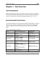
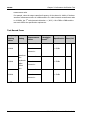
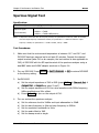
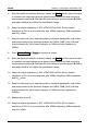
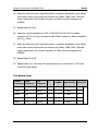
RIGOL Performance Verification Guide DG1000Z Series Function/Arbitrary Waveform Generator Mar. 2014 RIGOL Technologies, Inc. RIGOL Guaranty and Declaration Copyright © 2014 RIGOL Technologies, Inc. All Rights Reserved. Trademark Information RIGOL is a registered trademark of RIGOL Technologies, Inc. Publication Number PVB09101-1110 Notices RIGOL products are protected by patent law in and outside of P.R.C. RIGOL reserves the right to modify or change parts of or all the specifications and pricing policies at company’s sole decision. Information in this publication replaces all previously corresponding material. RIGOL shall not be liable for losses caused by either incidental or consequential in connection with the furnishing, use or performance of this manual as well as any information contained. Any part of this document is forbidden to be copied or photocopied or rearranged without prior written approval of RIGOL. Product Certification RIGOL guarantees this product conforms to the national and industrial standards in China as well as the ISO9001:2008 standard and the ISO14001:2004 standard. Other international standard conformance certification is in progress. Contact Us If you have any problem or requirement when using our products or this manual, please contact RIGOL. E-mail: [email protected] Websites: www.rigol.com DG1000Z Performance Verification Guide I RIGOL General Safety Summary Please review the following safety precautions carefully before putting the instrument into operation so as to avoid any personal injury or damage to the instrument and any product connected to it. To prevent potential hazards, please use the instrument only specified by this manual. Use Proper Power Cord. Only the power cord designed for the instrument and authorized for use within the local country could be used. Ground The Instrument. The instrument is grounded through the Protective Earth lead of the power cord. To avoid electric shock, it is essential to connect the earth terminal of power cord to the Protective Earth terminal before any inputs or outputs. Connect the Probe Correctly. If a probe is used, do not connect the ground lead to high voltage since it has the isobaric electric potential as ground. Observe All Terminal Ratings. To avoid fire or shock hazard, observe all ratings and markers on the instrument and check your manual for more information about ratings before connecting. Use Proper Overvoltage Protection. Make sure that no overvoltage (such as that caused by a thunderstorm) can reach the product, or else the operator might expose to danger of electrical shock. Do Not Operate Without Covers. Do not operate the instrument with covers or panels removed. Do Not Insert Anything into the Holes of Fan. Do not insert anything into the holes of the fan to avoid damaging the instrument. Use Proper Fuse. Please use the specified fuses. II DG1000Z Performance Verification Guide RIGOL Avoid Circuit or Wire Exposure. Do not touch exposed junctions and components when the unit is powered. Do Not Operate With Suspected Failures. If you suspect damage occurs to the instrument, have it inspected by qualified service personnel before further operations. Any maintenance, adjustment or replacement especially to circuits or accessories must be performed by RIGOL authorized personnel. Keep Well Ventilation. Inadequate ventilation may cause increasing of temperature or damages to the device. So please keep well ventilated and inspect the intake and fan regularly. Do Not Operate in Wet Conditions. In order to avoid short circuiting to the interior of the device or electric shock, please do not operate in a humid environment. Do Not Operate in an Explosive Atmosphere. In order to avoid damages to the device or personal injuries, it is important to operate the device away from an explosive atmosphere. Keep Product Surfaces Clean and Dry. To avoid the influence of dust and/or moisture in air, please keep the surface of device clean and dry. Electrostatic Prevention. Operate in an electrostatic discharge protective area environment to avoid damages induced by static discharges. Always ground both the internal and external conductors of the cable to release static before connecting. Proper Use of Battery. If a battery is supplied, it must not be exposed to high temperature or in contact with fire. Keep it out of the reach of children. Improper change of battery (note: lithium battery) may cause explosion. Use RIGOL specified battery only. DG1000Z Performance Verification Guide III RIGOL Handling Safety. Please handle with care during transportation to avoid damages to buttons, knob interfaces and other parts on the panels. IV DG1000Z Performance Verification Guide RIGOL Allgemeine Sicherheits Informationen Überprüfen Sie diefolgenden Sicherheitshinweise sorgfältigumPersonenschädenoderSchäden am Gerätundan damit verbundenen weiteren Gerätenzu vermeiden. Zur Vermeidung vonGefahren, nutzen Sie bitte das Gerät nur so, wiein diesem Handbuchangegeben. Um Feuer oder Verletzungen zu vermeiden, verwenden Sie ein ordnungsgemäßes Netzkabel. Verwenden Sie für dieses Gerät nur das für ihr Land zugelassene und genehmigte Netzkabel. Erden des Gerätes. Das Gerät ist durch den Schutzleiter im Netzkabel geerdet. Um Gefahren durch elektrischen Schlag zu vermeiden, ist es unerlässlich, die Erdung durchzuführen. Erst dann dürfen weitere Ein- oder Ausgänge verbunden werden. Anschluss einesTastkopfes. Die Erdungsklemmen der Sonden sindauf dem gleichen Spannungspegel des Instruments geerdet. SchließenSie die Erdungsklemmen an keine hohe Spannung an. Beachten Sie alle Anschlüsse. Zur Vermeidung von Feuer oder Stromschlag, beachten Sie alle Bemerkungen und Markierungen auf dem Instrument. Befolgen Sie die Bedienungsanleitung für weitere Informationen, bevor Sie weitere Anschlüsse an das Instrument legen. Verwenden Sie einen geeigneten Überspannungsschutz. Stellen Sie sicher, daß keinerlei Überspannung (wie z.B. durch Gewitter verursacht) das Gerät erreichen kann. Andernfallsbestehtfür den Anwender die GefahreinesStromschlages. Nicht ohne Abdeckung einschalten. Betreiben Sie das Gerät nicht mit entfernten Gehäuse-Abdeckungen. Betreiben Sie das Gerät nicht geöffnet. Der Betrieb mit offenen oder entfernten Gehäuseteilen ist nicht zulässig. Nichts in entsprechende Öffnungen stecken (Lüfter z.B.) Passende Sicherung verwenden. Setzen Sie nur die spezifikationsgemäßen Sicherungen ein. DG1000Z Performance Verification Guide V RIGOL Vermeiden Sie ungeschützte Verbindungen. Berühren Sie keine unisolierten Verbindungen oder Baugruppen, während das Gerät in Betrieb ist. Betreiben Sie das Gerät nicht im Fehlerfall. Wenn Sie am Gerät einen Defekt vermuten, sorgen Sie dafür, bevor Sie das Gerät wieder betreiben, dass eine Untersuchung durch qualifiziertes Kundendienstpersonal durchgeführt wird. Jedwede Wartung, Einstellarbeiten oder Austausch von Teilen am Gerät, sowie am Zubehör dürfen nur von RIGOL autorisiertem Personal durchgeführt werden. Belüftung sicherstellen. Unzureichende Belüftung kann zu Temperaturanstiegen und somit zu thermischen Schäden am Gerät führen. Stellen Sie deswegen die Belüftung sicher und kontrollieren regelmäßig Lüfter und Belüftungsöffnungen. Nicht in feuchter Umgebung betreiben. Zur Vermeidung von Kurzschluß im Geräteinneren und Stromschlag betreiben Sie das Gerät bitte niemals in feuchter Umgebung. Nicht in explosiver Atmosphäre betreiben. Zur Vermeidung von Personen- und Sachschäden ist es unumgänglich, das Gerät ausschließlich fernab jedweder explosiven Atmosphäre zu betreiben. Geräteoberflächen sauber und trocken halten. Um den Einfluß von Staub und Feuchtigkeit aus der Luft auszuschließen, halten Sie bitte die Geräteoberflächen sauber und trocken. Schutz gegen elektrostatische Entladung (ESD). Sorgen Sie für eine elektrostatisch geschützte Umgebung, um somit Schäden und Funktionsstörungen durch ESD zu vermeiden. Erden Sie vor dem Anschluß immer Innen- und Außenleiter der Verbindungsleitung, um statische Aufladung zu entladen. Die richtige Verwendung desAkku. Wenneine Batterieverwendet wird, vermeiden Sie hohe Temperaturen bzw. Feuer ausgesetzt werden. Bewahren Sie es außerhalbder Reichweitevon Kindern auf. UnsachgemäßeÄnderung derBatterie(Anmerkung:Lithium-Batterie)kann zu einer Explosion führen. VerwendenSie nur von RIGOLangegebenenAkkus. Sicherer Transport. Transportieren Sie das Gerät sorgfältig (Verpackung!), um Schäden an Bedienelementen, Anschlüssen und anderen Teilen zu vermeiden. VI DG1000Z Performance Verification Guide RIGOL Document Overview This manual is used to guide users to correctly test the performance specifications of DG1000Z series function/arbitrary waveform generator. The performance verification test mainly verifies whether DG1000Z series function/arbitrary waveform generator can work normally and is within specifications. Main topics in this Manual: Chapter 1 Test Overview This chapter introduces the preparations before the performance verification test, the recommended test devices, the test result record, the test notices and the related information of the technical parameters. Chapter 2 Performance Verification Test This chapter introduces the test method, procedures and limits of each performance specification in details. Appendix The appendix provides the test results record forms and performance specifications of DG1000Z series function/arbitrary waveform generator. Format Conventions in this Manual: 1. Button The front-panel key is denoted by the format of “Button Name (Bold) + Text Box” in the manual, for example, Utility denotes the “Utility” key. 2. Menu The menu is denoted by the format of “Menu Word (Bold) + Character Shading” in the manual, for example, System denotes the “System” menu item under Utility. 3. Operation Step The next step of the operation is denoted by an arrow “” in the manual. For example, Utility System denotes pressing Utility at the front panel and then pressing System. DG1000Z Performance Verification Guide VII RIGOL Content Conventions in this Manual: DG1000Z series function/arbitrary waveform generator includes the following models. Unless otherwise noted in this manual, DG1062Z is taken as an example to illustrate the performance verification test methods of DG1000Z series. VIII Model Number of Channels Max. Output Frequency DG1062Z 2 60MHz DG1032Z 2 30MHz DG1000Z Performance Verification Guide Contents RIGOL Contents Guaranty and Declaration .........................................................................I General Safety Summary ........................................................................ II Allgemeine Sicherheits Informationen ..................................................... V Document Overview.............................................................................. VII Chapter 1 Test Overview .................................................................... 1-1 Test Preparations................................................................................... 1-1 Recommended Test Devices ................................................................... 1-1 Test Result Record ................................................................................. 1-2 Test Notices .......................................................................................... 1-2 Technical Parameters ............................................................................. 1-3 Chapter 2 Performance Verification Test ............................................ 2-1 Frequency Accuracy Test ........................................................................ 2-2 AC Amplitude Accuracy Test ................................................................... 2-4 DC Offset Accuracy Test ......................................................................... 2-7 AC Flatness Test .................................................................................... 2-9 Harmonic Distortion Test .......................................................................2-12 Spurious Signal Test .............................................................................2-15 Rise/Fall Time Test ...............................................................................2-18 Overshoot Test .....................................................................................2-20 Appendix .................................................................................................. 1 Appendix A: Test Result Record Form ......................................................... 1 Appendix B: Performance Specifications ..................................................... 9 DG1000Z Performance Verification Guide IX RIGOL Chapter 1 Test Overview Chapter 1 Test Overview Test Preparations Before performing the test, make sure that the instrument is within the calibration period (the recommended calibration period is 1 year) and has been warmed up for at least 30 minutes under the specified operation temperature (18℃ to 28℃). Recommended Test Devices It is recommended that you use the test devices listed in the table below or other test devices whose performance specifications satisfy the “Performance Requirement” listed in the table below to test the performance specifications of the DG1000Z series. Table 1-1 Recommended test devices Recommended Device Performance Requirement Frequency Counter >10MHz Accuracy: 0.1ppm Agilent 53131A Digital Multimeter 61/2 digits RIGOL DM3068 Power Meter -30dBm to +20dBm Accuracy: ±0.02dB Resolution: 0.01dB Agilent E4418B Spectrum Analyzer Minimum resolution bandwidth is 100Hz RIGOL DSA815 Oscilloscope Bandwidth: 500MHz Rise/Fall time measurement function Overshoot measurement function RIGOL DS4000 series Connecting Cable BNC (m)-BNC (m) -- Connecting Cable BNC (m)-Dual banana plug (m) -- DG1000Z Performance Verification Guide Instrument 1-1 RIGOL Chapter 1 Test Overview 50Ω Load 50Ω/1W -- Power Sensor -30dBm to +20dBm Agilent N8482A Power Sensor Connecting Cable Used to connect the power meter and power sensor -- Adaptor N (f)-BNC (m) -- Adaptor BNC (f)-N (m) -- Test Result Record Record and keep the test results of each test item. The test result record forms, which provide all the test items and the corresponding performance specification limits as well as spaces for users to record the test results, are provided in “Appendix A: Test Result Record Form” of this manual. Tip: It is recommended that you photocopy the test result record form before each test. During the test process, record the test results on the copies so that the forms can be used repeatedly. Test Notices To achieve optimum test effect, all the test procedures should follow the following recommendations. 1) Make sure that the environment temperature is between 18℃ and 28℃ and every test is performed under the specified operation temperature (18℃ to 28℃). 2) Before performing each test, make sure that the instrument has been warmed up for at least 30 minutes. Before performing each test, restore the instrument to factory setting. 3) 1-2 DG1000Z Performance Verification Guide Chapter 1 Test Overview RIGOL Technical Parameters Chapter 2 of this manual provides the corresponding specification of each test item. Besides, “Appendix B: Performance Specifications” provides the detailed performance specifications of DG1000Z series. DG1000Z Performance Verification Guide 1-3 Chapter 2 Performance Verification Test RIGOL Chapter 2 Performance Verification Test This chapter introduces the performance verification test methods of DG1000Z series function/arbitrary waveform generator by taking CH1 of DG1062Z as an example. The test methods are also applicable to CH2. The test items include: Frequency Accuracy Test AC Amplitude Accuracy Test DC Offset Accuracy Test AC Flatness Test Harmonic Distortion Test Spurious Signal Test Rise/Fall Time Test Overshoot Test DG1000Z Performance Verification Guide 2-1 RIGOL Chapter 2 Performance Verification Test Frequency Accuracy Test Specification: Frequency characteristic ±1ppm of setting value[1], 18℃ to 28℃ Accuracy Note[1]: ppm denotes one part per million. For example, if the setting frequency is 1MHz and the actual output frequency is between 0.999 999MHz (-1ppm) and 1.000 001MHz (+1ppm), the instrument is up to the specification requirement and the test passes. Test Procedures: 1. Make sure that the environment temperature is between 18℃ and 28℃ and DG1000Z has been warmed up for at least 30 minutes. Connect the channel output terminal (take CH1 as an example; the test method is also applicable to CH2) of DG1000Z with the signal input terminal of the frequency counter using a dual-BNC cable as shown in Figure 2-1. DG1000Z Series Frequency Counter ◎ Figure 2-1 Connect DG1000Z and the Frequency Counter 2. Turn on the frequency counter and set its output impedance to 1MΩ. 3. Turn on DG1000Z. Press Utility Set To Default OK to restore DG1000Z to the factory setting. 4. Set DG1000Z: a) Set the output waveform of CH1 to a sine waveform with 1MHz frequency and 1Vpp amplitude. b) Press Output1 to turn on the output of CH1. 2-2 DG1000Z Performance Verification Guide RIGOL Chapter 2 Performance Verification Test 5. Record the reading of the frequency counter and judge whether the reading is between 0.999 999MHz and 1.000 001MHz. 6. Set CH1 of DG1000Z to output square, ramp and pulse waveforms (the frequencies are 1MHz and the amplitudes are 1Vpp) respectively. Record the readings of the frequency counter respectively and judge whether the readings are between 0.999 999MHz and 1.000 001MHz. 7. Repeat steps 1 to 6 to test the frequency accuracy of CH2 and record the test results. Test Record Form: Waveform Sine Setting Measurement Value Value Specification Frequency: Square 1MHz 0.999 999MHz to Ramp Amplitude: 1.000 001MHz Pulse Pass/Fail 1Vpp DG1000Z Performance Verification Guide 2-3 RIGOL Chapter 2 Performance Verification Test AC Amplitude Accuracy Test Specification: Output Characteristic Amplitude (into 50Ω) Typical (1kHz Sine, 0VDC Offset, >10mVpp, Auto) Accuracy ±1% of setting value ±1mV Test Procedures: 1. Make sure that the environment temperature is between 18℃ and 28℃ and DG1000Z has been warmed up for at least 30 minutes. Connect the 50Ω load to the channel output terminal (take CH1 as an example; the test method is also applicable to CH2) of DG1000Z; connect the 50Ω load and the voltage input terminals of the digital multimeter using a BNC-Dual banana plug connecting cable as shown in Figure 2-2. DG1000Z Series Digital Multimeter ◎ ◎ ◎ ◎ ◎ 50Ω Load Figure 2-2 Connect DG1000Z and the Digital Multimeter via a 50Ω Load 2. Turn on the multimeter, select the ACV measurement function and set the range to “Auto”. 3. Turn on DG1000Z. Press Utility Set To Default OK to restore DG1000Z to the factory setting. 4. Set DG1000Z: a) Set the output impedance of CH1 to 50Ω (press Utility Channel Set Output Set Imped and select “Load”). 2-4 DG1000Z Performance Verification Guide RIGOL Chapter 2 Performance Verification Test b) c) Set the output waveform of CH1 to a sine waveform with 1kHz frequency, 20mVpp amplitude and 0VDC offset. Press Output1 to turn on the output of CH1. 5. Record the reading of the multimeter and judge whether it is within the specification (“Amplitude Output Value (Vrms)” in Table 2-1) range. 6. Keep the output impedance of CH1 of DG1000Z at 50Ω and the output waveform of CH1 as a sine waveform with 1kHz frequency and 0VDC offset. Set the output amplitude of CH1 to 100mVpp, 500mVpp, 1Vpp, 5Vpp and 10Vpp respectively. Record the readings of the multimeter respectively and judge whether the readings are within the specification (“Amplitude Output Value (Vrms)” in Table 2-1) range. Table 2-1 Amplitude output values (Vrms) of AC amplitude accuracy test Amplitude Setting Allowed Amplitude Output Amplitude Output Value Value Error (Vpp)[1] Value (Vpp) (Vrms)[2] 20mVpp ±1.2mVpp 18.8mVpp to 21.2mVpp 6.6mVrms to 7.5mVrms 100mVpp ±2mVpp 98mVpp to 102mVpp 34.7mVrms to 36.1mVrms 500mVpp ±6mVpp 494mVpp to 506mVpp 174.7mVrms to 178.9mVrms 1Vpp ±11mVpp 0.989Vpp to 1.011Vpp 349.7mVrms to 357.5mVrms 5Vpp ±51mVpp 4.949Vpp to 5.051Vpp 1.75Vrms to 1.7861Vrms 10Vpp ±101mVpp 9.899Vpp to 10.101Vpp 3.5Vrms to 3.5717Vrms (Vpp) Note[1]: “Allowed Error” is calculated from the specification “±1% of setting value ±1mVpp”. Note[2]: “Amplitude Output Value (Vrms)” is calculated from “Amplitude Output Value (Vpp)”. The conversion relation between Vrms and Vpp is Vpp = 2 2Vrms . 7. Repeat steps 1 to 6 to test the AC amplitude accuracy of CH2 and record the test results. DG1000Z Performance Verification Guide 2-5 RIGOL Chapter 2 Performance Verification Test Test Record Form: Amplitude Setting Setting Value 500mVpp 1Vpp 5Vpp 10Vpp 2-6 Value Specification Pass/Fail 6.6mVrms to 7.5mVrms 20mVpp 100mVpp Measurement Frequency: 1kHz Offset: 0VDC Impedance: 50Ω 34.7mVrms to 36.1mVrms 174.7mVrms to 178.9mVrms 349.7mVrms to 357.5mVrms 1.75Vrms to 1.7861Vrms 3.5Vrms to 3.5717Vrms DG1000Z Performance Verification Guide Chapter 2 Performance Verification Test RIGOL DC Offset Accuracy Test Specification: Output Characteristic Offset (into 50Ω) Accuracy ±(1% of setting value + 5mV + 0.5% of amplitude) Test Procedures: 1. Make sure that the environment temperature is between 18℃ and 28℃ and DG1000Z has been warmed up for at least 30 minutes. Connect the 50Ω load to the channel output terminal (take CH1 as an example; the test method is also applicable to CH2) of DG1000Z; connect the 50Ω load and the voltage input terminals of the digital multimeter using a BNC-Dual banana plug connecting cable as shown in Figure 2-2. 2. Turn on the multimeter, select the DCV measurement function and set the range to “20V”. 3. Turn on DG1000Z. Press Utility Set To Default OK to restore DG1000Z to the factory setting. 4. Set DG1000Z: a) Set the output impedance of CH1 to 50Ω (press Utility Channel Set Output Set Imped and select “Load”). b) Set the output waveform of CH1 to a sine waveform with 1kHz frequency, 5Vpp amplitude and 0VDC offset. c) Press Output1 to turn on the output of CH1. 5. Record the reading of the multimeter and judge whether it is within the specification (“Offset” in Table 2-2) range. 6. Keep the output impedance of CH1 of DG1000Z at 50Ω and the output waveform of CH1 as a sine waveform with 1kHz frequency and 5Vpp amplitude. Set the offset of the output waveform of CH1 to -2.5VDC, -1VDC, -500mVDC, 500mVDC, 1VDC and 2.5VDC respectively. Record the readings of the multimeter DG1000Z Performance Verification Guide 2-7 RIGOL Chapter 2 Performance Verification Test respectively and judge whether the readings are within the specification (“Offset” in Table 2-2) range. Table 2-2 Offset limits of DC offset accuracy test Offset Setting Amplitude Value Setting Value Allowed Error[1] Offset[2] -2.5VDC ±0.005VDC -2.505VDC to -2.495VDC -1VDC ±0.020VDC -1.02VDC to -0.98VDC -500mVDC ±0.025VDC -0.525VDC to -0.475VDC ±0.030VDC -0.030VDC to 0.030VDC 500mVDC ±0.035VDC 0.465VDC to 0.535VDC 1VDC ±0.040VDC 0.96VDC to 1.04VDC 2.5VDC ±0.055VDC 2.445VDC to 2.555VDC 0VDC 5Vpp [1] Note : “Allowed Error” is calculated from the specification “± (1% of setting value + 5 mV + 0.5% of amplitude)”. [2] Note 7. : Offset = offset setting value ± allowed error. Repeat steps 1 to 6 to test the DC offset accuracy of CH2 and record the test results. Test Record Form: Offset Setting Setting Value Measurement Value Specification -2.505VDC to -2.495VDC -2.5VDC -1VDC Frequency: -1.02VDC to -0.98VDC -500mVDC 1kHz -0.525VDC to -0.475VDC 0VDC Amplitude: 5Vpp -0.030VDC to 0.030VDC 500mVDC Impedance: 0.465VDC to 0.535VDC 1VDC 50Ω 0.96VDC to 1.04VDC 2.5VDC 2-8 Pass/Fail 2.445VDC to 2.555VDC DG1000Z Performance Verification Guide Chapter 2 Performance Verification Test RIGOL AC Flatness Test Specification: Output Characteristic Typical (Sine, 2.5Vpp) Flatness ≤10MHz: ±0.1dB ≤60MHz: ±0.2dB Test Procedures: 1. Make sure that the environment temperature is between 18℃ and 28℃ and DG1000Z has been warmed up for at least 30 minutes. Connect the 50Ω load to the channel output terminal (take CH1 as an example; the test method is also applicable to CH2) of DG1000Z; connect the 50Ω load and the voltage input terminals of the digital multimeter using a BNC-Dual banana plug connecting cable as shown in Figure 2-2. 2. Turn on DG1000Z. Press Utility Set To Default OK to restore DG1000Z to the factory setting. 3. Set DG1000Z: a) Set the output impedance of CH1 to 50Ω (press Utility Channel Set Output Set Imped and select “Load”). b) Set the output waveform of CH1 to a sine waveform with 1kHz frequency and 2.5Vpp amplitude. c) Press Output1 to turn on the output of CH1. 4. Turn on the multimeter and select the ACV measurement function. Turn on the dBm operation function and set the reference resistance to 50Ω. Read the measurement value and take it as the reference power (Pref). Tip: In this step, if the dBm operation function is not turned on, you can also calculate the reference power using the formula dBm = 10 × Log10 [(Vreading 2 / Rref ) / 1mW ] according to the measurement value of DG1000Z Performance Verification Guide 2-9 RIGOL Chapter 2 Performance Verification Test the multimeter. Wherein, Vreading is the measurement value of the multimeter. 5. Calibrate the power meter: a) Connect the power sensor to the input terminal and [POWER REF] terminal of the power meter respectively. b) Press Zero/Cal Zero Cal. Turn on power reference after the calibration finishes and observe whether the measurement value of the power meter is a 0dBm, 50MHz signal. c) Turn off power reference. 6. Disconnect DG1000Z and the multimeter. Connect the power sensor and the channel output terminal (take CH1 as an example; the test method is also applicable to CH2) of DG1000Z using a BNC (f)-N (m) adaptor, as shown in Figure 2-3. DG1000Z Series Power Meter ◎ Figure 2-3 Connect DG1000Z and the Power Meter 7. Keep the output impedance of CH1 of DG1000Z at 50Ω. Set the output waveform of CH1 as a sine waveform with 5MHz frequency and 2.5Vpp amplitude. Set the frequency factor of the power meter to 5MHz, record the measurement value of the power meter and judge whether “measurement value-Pref” is between -0.1dB and +0.1dB. 8. Keep the output impedance of CH1 of DG1000Z at 50Ω. Set the output waveform of CH1 as a sine waveform with 10MHz frequency and 2.5Vpp 2-10 DG1000Z Performance Verification Guide RIGOL Chapter 2 Performance Verification Test amplitude. Set the frequency factor of the power meter to 10MHz, record the measurement value of the power meter and judge whether “measurement value-Pref” is between -0.1dB and +0.1dB. 9. Keep the output impedance of CH1 of DG1000Z at 50Ω. Set the output waveform of CH1 as a sine waveform with 30MHz frequency and 2.5Vpp amplitude. Set the frequency factor of the power meter to 30MHz, record the measurement value of the power meter and judge whether “measurement value-Pref” is between -0.2dB and +0.2dB. 10. Keep the output impedance of CH1 of DG1000Z at 50Ω. Set the output waveform of CH1 as a sine waveform with 60MHz frequency and 2.5Vpp amplitude. Set the frequency factor of the power meter to 60MHz, record the measurement value of the power meter and judge whether “measurement value-Pref” is between -0.2dB and +0.2dB. 11. Repeat steps 1 to 10 to test the AC flatness of CH2 and record the test results. Test Record Form: Frequency Setting Setting Value 5MHz Calculation Value Result[1] Amplitude: 10MHz 2.5Vpp 30MHz Impedance: 60MHz Measurement 50Ω Specification Pass/Fail ±0.1dB ±0.2dB Note[1]: Calculation result = Measurement value - Pref. DG1000Z Performance Verification Guide 2-11 RIGOL Chapter 2 Performance Verification Test Harmonic Distortion Test Specification: Sine Wave Spectrum Purity Typical (0dBm) Harmonic Distortion DC to 10MHz (include 10MHz): <-65dBc 10MHz to 30MHz (include 30MHz): <-55dBc 30MHz to 60MHz (include 60MHz): <-50dBc Test Procedures: 1. Make sure that the environment temperature is between 18℃ and 28℃ and DG1000Z has been warmed up for at least 30 minutes. Connect the channel output terminal (take CH1 as an example; the test method is also applicable to CH2) of DG1000Z with the signal input terminal of the spectrum analyzer using a dual-BNC connecting cable and N-BNC adaptor as shown in Figure 2-4. DG1000Z Series Spectrum Analyzer ◎ Figure 2-4 Connect DG1000Z and the Spectrum Analyzer 2. Turn on DG1000Z. Press Utility Set To Default OK to restore DG1000Z to the factory setting. 3. Set DG1000Z: a) Set the output impedance of CH1 to 50Ω (press Utility Channel Set Output Set Imped and select “Load”). b) Set the output waveform of CH1 to a sine waveform with 10MHz frequency, 0dBm amplitude and 0VDC offset. c) Press Output1 to turn on the output of CH1. 2-12 DG1000Z Performance Verification Guide Chapter 2 Performance Verification Test RIGOL 4. Turn on and set the spectrum analyzer: a) Set the reference level to 10dBm and input attenuation to 20dB. b) Set the start frequency to 5MHz and stop frequency to 30MHz. c) Set the resolution bandwidth to 3kHz. 5. Use the cursor function to make measurements and record the measurement values of the base waveform and 2nd order harmonic. Calculate[1] the harmonic distortion and judge whether it is less than -65dBc. 6. Keep the output impedance of CH1 of DG1000Z at 50Ω. Set the output waveform of CH1 as a sine waveform with 30MHz frequency, 0dBm amplitude and 0VDC offset. 7. Keep the reference level, input attenuation and resolution bandwidth of the spectrum analyzer as 10dBm, 20dB and 3kHz respectively. Set its start frequency to 20MHz and stop frequency to 70MHz. 8. Use the cursor function to make measurements and record the measurement values of the base waveform and 2nd order harmonic. Calculate[1] the harmonic distortion and judge whether it is less than -55dBc. 9. Keep the output impedance of CH1 of DG1000Z at 50Ω. Set the output waveform of CH1 as a sine waveform with 60MHz frequency, 0dBm amplitude and 0VDC offset. 10. Keep the input attenuation, reference level and resolution bandwidth of the spectrum analyzer as 20dB, 10dBm and 3kHz respectively. Set its start frequency to 50MHz and stop frequency to 150MHz. 11. Use the cursor function to make measurements and record the measurement values of the base waveform and 2nd order harmonic. Calculate[1] the harmonic distortion and judge whether it is less than -50dBc. 12. Repeat steps 1 to 11 to test the harmonic distortion of CH2 and record the test results. Note[1]: 2nd order harmonic distortion = 2nd order harmonic measurement value – base waveform DG1000Z Performance Verification Guide 2-13 RIGOL Chapter 2 Performance Verification Test measurement value For example, when the output waveform frequency of the channel is 10MHz, if the base waveform measurement value is 0.8dBm and the 2nd order harmonic measurement value is -66.2dBm, the 2nd order harmonic distortion = (-66.2) -0.8=-67dBc<-65dBc and the test result fulfills the specification requirement. Test Record Form: Frequency Setting Setting Value Measurement Calculation Value Result[1] Specification Pass/Fail Base waveform: 2nd order 10MHz <-65dBc harmonic: Waveform: Sine 30MHz Amplitude: 0dBm Offset: 0VDC 60MHz Base waveform: 2nd order <-55dBc harmonic: Base waveform: 2nd order <-50dBc harmonic: Note[1]: Calculation result = 2th order harmonic measurement value - base waveform measurement value. 2-14 DG1000Z Performance Verification Guide Chapter 2 Performance Verification Test RIGOL Spurious Signal Test Specification: Sine Wave Spectrum Purity (Typical 0dBm) Spurious signal (non-harmonic) Typical (0dBm) ≤10MHz: <-70dBc >10MHz: <-70dBc+6dB/octave[1] Note[1]: 6 dBc/octave means that when the frequency doubles, the specification increases by 6 dBc. For example, when the output frequency of DG1000Z is 10MHz, the specification is <-70dBc and when the output frequency is 30MHz, the specification is <-70dBc+2×6dBc, namely <-58dBc. Test Procedures: 1. Make sure that the environment temperature is between 18℃ and 28℃ and DG1000Z has been warmed up for at least 30 minutes. Connect the channel output terminal (take CH1 as an example; the test method is also applicable to CH2) of DG1000Z with the RF input terminal of the spectrum analyzer using a dual-BNC cable and N-BNC adaptor as shown in Figure 2-4. 2. Turn on DG1000Z. Press Utility Set To Default OK to restore DG1000Z to the factory setting. 3. Set DG1000Z: a) Set the output impedance of CH1 to 50Ω (press Utility Channel Set Output Set Imped and select “Load”). b) Set the output waveform of CH1 to a sine waveform with 5MHz frequency, 0dBm amplitude and 0VDC offset. d) Press Output1 to turn on the output of CH1. 4. Turn on and set the spectrum analyzer: a) Set the reference level to 10dBm and input attenuation to 20dB. b) Set the start frequency to 0Hz and stop frequency to 30MHz. c) Set the resolution bandwidth to 1kHz. d) Set the peak offset to 3dB. e) Set the sweep mode to single. DG1000Z Performance Verification Guide 2-15 RIGOL Chapter 2 Performance Verification Test 5. After the spectrum analyzer finishes a sweep, use Peak and the cursor function to measure the maximum spurious signal (except harmonics) and record the measurement result as A. Calculate the non-harmonic spurious signal (A-0dBm) and judge whether it is within the specification range. 6. Keep the output impedance of CH1 of DG1000Z at 50Ω. Set the output waveform of CH1 as a sine waveform with 10MHz frequency, 0dBm amplitude and 0VDC offset. 7. Keep the reference level, input attenuation, resolution bandwidth, peak offset and sweep mode of the spectrum analyzer as 10dBm, 20dB, 1kHz, 3dB and single respectively. Set its start frequency to 0MHz and stop frequency to 50MHz. 8. Press Sweep/Trig Single to perform a sweep. 9. After the spectrum analyzer finishes a sweep, use Peak and the cursor function to measure the maximum spurious signal (except harmonics) and record the measurement result as A. Calculate the non-harmonic spurious signal (A-0dBm) and judge whether it is within the specification range. 10. Keep the output impedance of CH1 of DG1000Z at 50Ω. Set the output waveform of CH1 as a sine waveform with 20MHz frequency, 0dBm amplitude and 0VDC offset. 11. Keep the reference level, input attenuation, resolution bandwidth, peak offset and sweep mode of the spectrum analyzer as 10dBm, 20dB, 1kHz, 3dB and single respectively. Set its start frequency to 0MHz and stop frequency to 100MHz. 12. Repeat steps 8 and 9. 13. Keep the output impedance of CH1 of DG1000Z at 50Ω. Set the output waveform of CH1 as a sine waveform with 30MHz frequency, 0dBm amplitude and 0VDC offset. 2-16 DG1000Z Performance Verification Guide RIGOL Chapter 2 Performance Verification Test 14. Keep the reference level, input attenuation, resolution bandwidth, peak offset and sweep mode of the spectrum analyzer as 10dBm, 20dB, 1kHz, 3dB and single respectively. Set its start frequency to 0MHz and stop frequency to 150MHz. 15. Repeat steps 8 and 9. 16. Keep the output impedance of CH1 of DG1000Z at 50Ω. Set the output waveform of CH1 as a sine waveform with 60MHz frequency, 0dBm amplitude and 0VDC offset. 17. Keep the reference level, input attenuation, resolution bandwidth, peak offset and sweep mode of the spectrum analyzer as 10dBm, 20dB, 1kHz, 3dB and single respectively. Set its start frequency to 0MHz and stop frequency to 300MHz. 18. Repeat steps 8 and 9. 19. Repeat steps 1 to 18 to test the spurious signal (non-harmonic) of CH2 and record the test results. Test Record Form: Output Start Stop Frequency Frequency Frequency 5MHz 0Hz 30MHz <-70dBc 10MHz 0Hz 50MHz <-70dBc 20MHz 0Hz 100MHz <-64dBc 30MHz 0Hz 150MHz <-58dBc 60MHz 0Hz 300MHz <-40dBc DG1000Z Performance Verification Guide A A-0dBm Specification Pass/Fail 2-17 RIGOL Chapter 2 Performance Verification Test Rise/Fall Time Test Specification: Signal Characteristic Square Typical (1Vpp) Rise/Fall Time <10ns Test Procedures: 1. Make sure that the environment temperature is between 18℃ and 28℃ and DG1000Z has been warmed up for at least 30 minutes. Connect the channel output terminal (take CH1 as an example; the test method is also applicable to CH2) of DG1000Z with the signal input terminal of the oscilloscope using a dual-BNC connecting cable as shown in Figure 2-5. DG1000Z Series Oscilloscope ◎ Figure 2-5 Connect DG1000Z and the Oscilloscope 2. Turn on DG1000Z. Press Utility Set To Default OK to restore DG1000Z to the factory setting. 3. Set DG1000Z: a) Set the output impedance of CH1 to 50Ω (press Utility Channel Set Output Set Imped and select “Load”). b) Set the output waveform of CH1 to a square waveform with 1MHz frequency, 1Vpp amplitude and 0VDC offset. c) Press Output1 to turn on the output of CH1. 2-18 DG1000Z Performance Verification Guide RIGOL Chapter 2 Performance Verification Test 4. Turn on and set the oscilloscope: a) Set the vertical scale to 200mV/div. b) Set the horizontal time base to 1ns. c) Adjust the trigger level to a proper value. d) Set the input impedance to 50Ω. e) Turn on the rise time and fall time measurement functions. 5. Set the edge type of the oscilloscope to rising edge, record the measurement result of the rise time and judge whether it is within the specification range. 6. Set the edge type of the oscilloscope to falling edge, record the measurement result of the fall time and judge whether it is within the specification range. 7. Repeat steps 1 to 6 to test the rise/fall time of CH2 and record the measurement results. Test Record Form: Waveform Square Setting Measurement Value Specification Frequency: 1MHz Rise Time Typical (1Vpp) Fall Time <10ns Amplitude: 1Vpp Offset: 0VDC DG1000Z Performance Verification Guide Pass/Fail 2-19 RIGOL Chapter 2 Performance Verification Test Overshoot Test Specification: Signal Characteristic Square Overshoot Typical (100kHz, 1Vpp) ≤5% Test Procedures: 1. Make sure that the environment temperature is between 18℃ and 28℃ and DG1000Z has been warmed up for at least 30 minutes. Connect the channel output terminal (take CH1 as an example; the test method is also applicable to CH2) of DG1000Z with the signal input terminal of the oscilloscope using a dual-BNC connecting cable as shown in Figure 2-5. 2. Turn on DG1000Z. Press Utility Set To Default OK to restore DG1000Z to factory setting. 3. Set DG1000Z: a) Set the output impedance of CH1 to 50Ω (press Utility Channel Set Output Set Imped and select “Load”). b) Set the output waveform of CH1 to a square waveform with 100kHz frequency, 1Vpp amplitude and 0VDC offset. c) Press Output1 to turn on the output of CH1. 4. Turn on and set the oscilloscope: a) Set the input impedance to 50Ω. b) Set the vertical scale to 200mV/div. c) Set the horizontal time base to 50ns. d) Adjust the trigger level to a proper value. e) Turn on the overshoot measurement function. 5. Record the overshoot measurement value and judge whether it is within the specification range. 2-20 DG1000Z Performance Verification Guide RIGOL Chapter 2 Performance Verification Test 6. Repeat steps 1 to 5 to test the overshoot of CH2 and record the measurement result. Test Record Form: Waveform Square Setting Measurement Value Specification Frequency: 100kHz Typical (100kHz, Amplitude: 1Vpp 1Vpp) Offset: 0VDC <5% DG1000Z Performance Verification Guide Pass/Fail 2-21 RIGOL Appendix Appendix Appendix A: Test Result Record Form RIGOL DG1000Z Series Function/Arbitrary Waveform Generator Performance Verification Test Record Form Model: Tested by: Test Date: Channel: CH1 Frequency Accuracy Test Waveform Sine Setting Measurement Value Value Specification Frequency: Square 1MHz 0.999 999MHz to Ramp Amplitude: 1.000 001MHz Pulse Pass/Fail 1Vpp AC Amplitude Accuracy Test Amplitude Setting Setting Value Measurement Value 500mVpp 1Vpp 5Vpp Pass/Fail 6.6mVrms to 7.5mVrms 20mVpp 100mVpp Specification Frequency: 1kHz Offset: 0VDC Impedance: 50Ω 10Vpp[1] 34.7mVrms to 36.1mVrms 174.7mVrms to 178.9mVrms 349.7mVrms to 357.5mVrms 1.75Vrms to 1.7861Vrms 3.5Vrms to 3.5717Vrms Note[1]: Only applicable to DG1062Z. DG1000Z Performance Verification Guide 1 RIGOL Appendix DC Offset Accuracy Test Offset Setting Setting Value Measurement Value Specification Pass/Fail -2.505VDC to -2.495VDC -2.5VDC -1VDC Frequency: -1.02VDC to -0.98VDC -500mVDC 1kHz -0.525VDC to -0.475VDC 0VDC Amplitude: -0.030VDC to 0.030VDC 5Vpp 500mVDC Impedance: 0.465VDC to 0.535VDC 1VDC 50Ω 0.96VDC to 1.04VDC 2.5VDC 2.445VDC to 2.555VDC AC Flatness Test Frequency Setting Setting Value 5MHz Amplitude: 10MHz 2.5Vpp 30MHz Impedance: 60MHz[1] 50Ω Measurement Calculation Value Result Specification Pass/Fail ±0.1dB ±0.2dB Note[1]: Only applicable to DG1062Z. 2 DG1000Z Performance Verification Guide RIGOL Appendix Harmonic Distortion Test Frequency Setting Setting Value Measurement Calculation Value Result Specification Pass/Fail Base waveform: 2nd order 10MHz <-65dBc harmonic: Waveform: Sine 30MHz Amplitude: 0dBm Offset: 0VDC 60MHz[1] Base waveform: 2nd order <-55dBc harmonic: Base waveform: 2nd order <-50dBc harmonic: Note[1]: Only applicable to DG1062Z. Spurious Signal Test Output Start Stop Frequency Frequency Frequency 5MHz 0Hz 30MHz <-70dBc 10MHz 0Hz 50MHz <-70dBc 20MHz 0Hz 100MHz <-64dBc 30MHz 0Hz 150MHz <-58dBc 60MHz[1] 0Hz 300MHz <-40dBc A A-0dBm Specification Pass/Fail [1] Note : Only applicable to DG1062Z. DG1000Z Performance Verification Guide 3 RIGOL Appendix Rise/Fall Time Test Waveform Square Setting Measurement Value Specification Frequency: 1MHz Rise Time Typical (1Vpp) Fall Time <10ns Measurement Value Specification Amplitude: 1Vpp Offset: 0VDC Pass/Fail Overshoot Test Waveform Square 4 Setting Frequency: 100kHz Typical (100kHz, Amplitude: 1Vpp 1Vpp) Offset: 0VDC <5% Pass/Fail DG1000Z Performance Verification Guide RIGOL Appendix Channel: CH2 Frequency Accuracy Test Waveform Sine Setting Measurement Value Value Specification Pass/Fail Frequency: Square 1MHz 0.999 999MHz to Ramp Amplitude: 1.000 001MHz Pulse 1Vpp AC Amplitude Accuracy Test Amplitude Setting Setting Value Measurement Value 500mVpp 1Vpp Frequency: 1kHz Offset: 0VDC Impedance: 5Vpp Pass/Fail 6.6mVrms to 7.5mVrms 20mVpp 100mVpp Specification 50Ω 10Vpp[1] 34.7mVrms to 36.1mVrms 174.7mVrms to 178.9mVrms 349.7mVrms to 357.5mVrms 1.75Vrms to 1.7861Vrms 3.5Vrms to 3.5717Vrms [1] Note : Only applicable to DG1062Z. DG1000Z Performance Verification Guide 5 RIGOL Appendix DC Offset Accuracy Test Offset Setting Setting Value Measurement Value Specification Pass/Fail -2.505VDC to -2.495VDC -2.5VDC -1VDC Frequency: -1.02VDC to -0.98VDC -500mVDC 1kHz -0.525VDC to -0.475VDC 0VDC Amplitude: -0.030VDC to 0.030VDC 5Vpp 500mVDC Impedance: 0.465VDC to 0.535VDC 1VDC 50Ω 0.96VDC to 1.04VDC 2.5VDC 2.445VDC to 2.555VDC AC Flatness Test Frequency Setting Setting Value 5MHz Amplitude: 10MHz 2.5Vpp 30MHz Impedance: 60MHz[1] 50Ω Measurement Calculation Value Result Specification Pass/Fail ±0.1dB ±0.2dB Note[1]: Only applicable to DG1062Z. 6 DG1000Z Performance Verification Guide RIGOL Appendix Harmonic Distortion Test Frequency Setting Setting Value Measurement Calculation Value Result Specification Pass/Fail Base waveform: 2nd order 10MHz <-65dBc harmonic: Waveform: Sine 30MHz Amplitude: 0dBm Offset: 0VDC 60MHz[1] Base waveform: 2nd order <-55dBc harmonic: Base waveform: 2nd order <-50dBc harmonic: Note[1]: Only applicable to DG1062Z. Spurious Signal Test Output Start Stop Frequency Frequency Frequency 5MHz 0Hz 30MHz <-70dBc 10MHz 0Hz 50MHz <-70dBc 20MHz 0Hz 100MHz <-64dBc 30MHz 0Hz 150MHz <-58dBc 60MHz[1] 0Hz 300MHz <-40dBc A A-0dBm Specification Pass/Fail [1] Note : Only applicable to DG1062Z. DG1000Z Performance Verification Guide 7 RIGOL Appendix Rise/Fall Time Test Waveform Square Setting Measurement Value Specification Frequency: 1MHz Rise Time Typical (1Vpp) Fall Time <10ns Measurement Value Specification Amplitude: 1Vpp Offset: 0VDC Pass/Fail Overshoot Test Waveform Square 8 Setting Frequency: 100kHz Typical (100kHz, Amplitude: 1Vpp 1Vpp) Offset: 0VDC <5% Pass/Fail DG1000Z Performance Verification Guide RIGOL Appendix Appendix B: Performance Specifications Unless otherwise specified, all the specifications can be guaranteed if the following two conditions are met. The generator is within the calibration period and has performed self-calibration. The generator has been working continuously for at least 30 minutes under the specified temperature (18℃~28℃). All the specifications are guaranteed unless those marked with “typical”. Model DG1032Z DG1062Z Channel 2 2 Maximum Frequency 30MHz 60MHz Sample Rate 200MSa/s Waveforms Basic waveforms Sine, Square, Ramp, Pulse, Noise Built-in Arbitrary Waveforms 160 kinds, including Sinc, Exponential Rise, Exponential Fall, ECG, Gauss, HaverSine, Lorentz, Dual-Tone, etc. Frequency Characteristics Sine 1μHz to 30MHz 1μHz to 60MHz Square 1μHz to 15MHz 1μHz to 25MHz Ramp 1μHz to 500kHz 1μHz to 1MHz Pulse 1μHz to 15MHz 1μHz to 25MHz Harmonic 1μHz to 10MHz 1μHz to 20MHz Noise (-3dB) 30MHz bandwidth 60MHz bandwidth Arbitrary Waveform 1μHz to 10MHz 1μHz to 20MHz Resolution 1μHz ±1ppm of the settings, 18℃ to 28℃ Accuracy DG1000Z Performance Verification Guide 9 RIGOL Appendix Sine Wave Spectrum Purity Harmonic Distortion Typical (0dBm) DC-10MHz (included): <-65dBc 10MHz-30MHz (included): <-55dBc 30MHz-60MHz (included): <-50dBc Total Harmonic Distortion <0.075% (10Hz-20kHz, 0dBm) Spurious (non-harmonic) Typical (0dBm) ≤10MHz: <-70dBc >10MHz: <-70dBc+6dB/octave Phase Noise Typical (0dBm, 10kHz deviation) 10MHz: <-125dBc/Hz Signal Characteristics Square Rise/Fall Time Typical (1Vpp) <10ns Overshoot Typical (100KHz, 1Vpp) ≤5% Duty Cycle 0.01% to 99.99% (limited by the current frequency setting) Non-symmetry 1% of period+5ns Jitter (rms) Typical (1Vpp) ≤5MHz: 2ppm+200ps >5MHz: 200ps Ramp Linearity ≤1% of peak output (typical, 1kHz, 1Vpp, 100% symmetry) Symmetry 0% to 100% Pulse Pulse Width ≥16ns (limited by the current frequency setting) Duty Cycle 0.001% to 99.999% (limited by the current frequency setting) Leading/Trailing Edge Time ≥10ns (limited by the current frequency and pulse width settings) 10 DG1000Z Performance Verification Guide RIGOL Appendix Overshoot Typical (1Vpp) ≤5% Jitter (rms) Typical (1Vpp) ≤5MHz: 2ppm+200ps >5MHz: 200ps Arb Waveform Length 8Sa to 8Mpts (16Mpts optional) Vertical Resolution 14bits Sample Rate 200MSa/s Minimum Rise/Fall Time Typical (1Vpp) <10ns Jitter (rms) Typical (1Vpp) ≤5MHz: 2ppm+200ps >5MHz: 200ps Edit Method Edit Points, Edit Block, Insert Waveform Harmonic Harmonic Order ≤8 Harmonic Type Even, Odd, All, User Harmonic Amplitude can be set for all harmonics Harmonic Phase can be set for all harmonics Output Characteristics Amplitude (into 50Ω) Range ≤10MHz: 2.5mVpp to 10Vpp ≤30MHz: 2.5mVpp to 5.0Vpp ≤60MHz: 2.5mVpp to 2.5Vpp Accuracy Typical (1kHz Sine, 0V Offset, >10mVpp, Auto) ±1% of setting ± 1mV Flatness Typical (Sine, 2.5Vpp) ≤10MHz: ±0.1dB ≤60MHz: ±0.2dB Units Vpp, Vrms, dBm Resolution 0.1mVpp or 4digits Offset (into 50Ω) Range (Peak ac+dc) ±5Vpkac+dc DG1000Z Performance Verification Guide 11 RIGOL Accuracy Appendix ±(1% of setting+5mV+0.5% of amplitude) Waveform Output Impedance 50Ω (typical) Protection Short-circuit protection, automatically disable waveform output when overload occurs Modulation Characteristics Modulation Type AM, FM, PM, ASK, FSK, PSK, PWM AM Carrier Waveform Sine, Square, Ramp, Arb (except DC) Source Internal/External Modulating Waveform Sine, Square, Ramp, Noise, Arb Depth 0% to 120% Modulating Frequency 2mHz to 1MHz FM Carrier Waveform Sine, Square, Ramp, Arb (except DC) Source Internal/External Modulating Waveform Sine, Square, Ramp, Noise, Arb Modulating Frequency 2mHz to 1MHz PM Carrier Waveform Sine, Square, Ramp, Arb (except DC) Source Internal/External Modulating Waveform Sine, Square, Ramp, Noise, Arb Phase Deviation 0° to 360° Modulating Frequency 2mHz to 1MHz ASK Carrier Waveform Sine, Square, Ramp, Arb (except DC) Source Internal/External Modulating Waveform Square with 50% duty cycle Key Frequency 2mHz to 1MHz FSK Carrier Waveform Sine, Square, Ramp, Arb (except DC) Source Internal/External Modulating Waveform Square with 50% duty cycle Key Frequency 2mHz to 1MHz 12 DG1000Z Performance Verification Guide RIGOL Appendix PSK Carrier Waveform Sine, Square, Ramp, Arb (except DC) Source Internal/External Modulating Waveform Square with 50% duty cycle Key Frequency 2mHz to 1MHz PWM Carrier Waveform Pulse Source Internal/External Modulating Waveforms Sine, Square, Ramp, Noise, Arb Width Deviation 0% to 100% of Pulse Width Modulating Frequency 2mHz to 1MHz External Modulation Input Max. Input Range ±5V Input Bandwidth 50kHz Input Impedance 10kΩ Burst Characteristics Carrier Waveform Sine, Square, Ramp, Pulse, Noise, Arb (except DC) Carrier Frequency 2mHz to 30MHz Burst Count 1 to 1,000,000 or Infinite Start/Stop Phase 0° to 360° Internal Period 1us to 500s Gated Source External Trigger Trigger Source Internal, External or Manual Trigger Delay 0ns to 100s 2mHz to 60MHz Sweep Characteristics Carrier Waveform Sine, Square, Ramp, Arb (except DC) Type Linear, Log or Step Direction Up/Down Start/Stop Frequency Consistent with the upper/lower limit of the frequency of the carrier waveform Sweep Time 1ms to 500s DG1000Z Performance Verification Guide 13 RIGOL Appendix Hold/Return Time 0ms to 500s Trigger Source Internal, External, Manual Mark Falling edge of the Sync signal (programmable) Counter Function Frequency, Period, Positive/Negative Pulse Width, Duty Cycle Frequency Resolution 7 digits/second (Gate Time =1s) Frequency Range 1μHz to 200MHz Period Measurement Measurement Range 5ns to 16 days Voltage Range and Sensitivity (Not modulation signal) DC Coupling AC Coupling DC Offset Range ±1.5Vdc 1μHz to 100MHz 50mVRMS to ±2.5Vac+dc 100MHz to 200MHz 100mVRMS to ±2.5Vac+dc 1μHz to 100MHz 50mVRMS to ±2.5Vpp 100MHz to 200MHz 100mVRMS to ±2.5Vpp Pulse Width and Duty Cycle Measurement Frequency/Amplitude Range Pulse Width Duty Cycle 1μHz to 25MHz 50mVRMS to ±2.5Vac+dc Minimum ≥20ns Resolution 5ns Range (Display) 0% to 100% Breakdown Voltage ±7Vac+dc Impedance= 1MΩ Coupling AC DC HF Suppression ON: input bandwidth=250kHz; OFF: input bandwidth=200MHz Trigger Level Range -2.5V to +2.5V Trigger Sensitivity Range 0% (about 140mV hysteresis voltage) to 100% (about 2mV hysteresis voltage) GateTime1 1.310ms GateTime2 10.48ms GateTime3 166.7ms DC Coupling Input Characteristics Input Signal Range Input Adjustment Input Trigger Gate Time 14 DG1000Z Performance Verification Guide RIGOL Appendix GateTime4 1.342s GateTime5 10.73s GateTime6 >10s Trigger Characteristics Trigger Input Level TTL-compatible Slope Rising or falling (optional) Pulse Width >100ns Latency Sweep: <100ns (typical) Burst: <300ns (typical) Trigger Output Level TTL-compatible Pulse Width >60ns (typical) Maximum Frequency 1MHz Clock Reference Phase Offset Range 0° to 360° Resolution 0.03° External Reference Input Lock Range 10MHz±50Hz Level 250mVpp to 5Vpp Lock Time <2s Input Impedance (typical) 1kΩ, AC coupling Internal Reference Output Frequency 10MHz±50Hz Level 3.3Vpp Output Impedance (typical) 50Ω, AC coupling DG1000Z Performance Verification Guide 15 RIGOL Appendix Sync Output Level TTL-compatible Impedance 50Ω, nominal value Overvoltage Protection Overvoltage protection will take effect once any of the following two conditions is met: The amplitude setting in the generator is greater than 2Vpp or the output offset is greater than |2VDC|, the input voltage is greater than ±11.5×(1±5%)V (<10kHz). The amplitude setting in the generator is lower than or equal to 2Vpp or the output offset is lower than or equal to |2VDC|, the input voltage is greater than ±3.5×(1±5%)V (<10kHz). General Specifications Power Power Voltage 100V to 240V (45Hz to 440Hz) Power Consumption Less than 40W Fuse 250V, T3.15A Display Type 3.5-inch TFT LCD Resolution 320 Horizontal×RGB×240 Vertical Resolution Color 16M color Environment Temperature Range Operating: 0℃ to 50℃ Non-Operating: -40℃ to 70℃ Cooling Method Cooling by fans compulsively Humidity Range Less than 30℃: ≤95% Relative Humidity (RH) 30℃ to 40℃: ≤75% Relative Humidity (RH) 40℃ to 50℃: ≤45% Relative Humidity (RH) Altitude Operating: Less than 3000 meters Non-Operating: Less than 15,000 meters Mechanical Dimensions (W×H×D) 16 261.5mm×112mm×318.4mm DG1000Z Performance Verification Guide RIGOL Appendix Weight without package: 3.2kg with package: 4.5kg Interfaces USB Host, USB Device, LAN IP Protection IP2X Calibration Interval Recommend calibration interval is one year Authentication Information In line with EN61326-1:2006 EMC Electrical Safety IEC 61000-3-2:2000 ±4.0kV (Contact Discharge) ±4.0kV (Air Discharge) IEC 61000-4-3:2002 3V/m (80MHz to 1GHz) 3V/m (1.4GHz to 2GHz) 1V/m (2.0GHz to 2.7GHz) IEC 61000-4-4:2004 1kV power lines IEC 61000-4-5:2001 0.5kV (Phase to Neutral) 0.5kV (Phase to PE) 1kV (Neutral to PE) IEC 61000-4-6:2003 3V, 0.15MHz to 80MHz EC 61000-4-11:2004 Voltage dip: 0%UT during half cycle 0%UT during 1 cycle 70%UT during 25 cycle Short interruption: 0%UT during 1 cycle In line with USA: UL 61010-1:2012, Canada: CAN/CSA-C22.2 No. 61010- 1-2012 EN 61010-1:2010 DG1000Z Performance Verification Guide 17