1
LBI-39117
INSTALLATION AND SET-UP MANUAL
C3 ADVANTAGE DISPATCH SYSTEM
TABLE OF CONTENTS
Page
GENERAL.......................................................................................................................................................
3
COMPACT CEC INSTALLATION .............................................................................................................
FLOOR PLAN .........................................................................................................................................
EQUIPMENT ROOM GROUNDING ...................................................................................................
AC POWER AND UPS EQUIPMENT ..................................................................................................
IN-CABINET DC POWER CABLES ....................................................................................................
LOCAL BUS CABLES............................................................................................................................
TERMINATOR BOARDS ......................................................................................................................
CONCENTRATOR CARD CABLES ....................................................................................................
UPLINK GETC CABLES.......................................................................................................................
EXTERNAL CONNECTIONS...............................................................................................................
Punch Blocks ......................................................................................................................................
External Cable Length And Shielding.................................................................................................
Audio ...........................................................................................................................................
RS-232/RS-422 Control Data ......................................................................................................
Telephone Lines..................................................................................................................................
CEC MANAGER (MOM PC) AND SYSTEM MANAGER CONNECTIONS .................................
AUXILIARY I/O OPTION MSDE3U....................................................................................................
3
3
3
3
4
4
4
5
5
5
5
5
5
5
6
6
6
C3 MAESTRO INSTALLATION .................................................................................................................
6
COMPACT CEC POWER-UP PROCEDURE............................................................................................
6
C3 MAESTRO POWER-UP PROCEDURE................................................................................................
8
C3 ADVANTAGE DATABASE CONFIGURATION .................................................................................
OVERVIEW.............................................................................................................................................
LID And GID Databases.....................................................................................................................
Site Database ......................................................................................................................................
WITHOUT SYSTEM MANAGER ........................................................................................................
LID And GID Databases.....................................................................................................................
Site Database ......................................................................................................................................
WITH SYSTEM MANAGER.................................................................................................................
8
8
8
8
8
8
9
9
COMPACT CEC SET-UP .............................................................................................................................
DIP SWITCH CONFIGURATION........................................................................................................
Controller Boards................................................................................................................................
Audio Boards ......................................................................................................................................
Conventional Interface Boards............................................................................................................
Uplink GETC......................................................................................................................................
10
10
10
11
12
12
ericssonz
LBI-39117
TABLE OF CONTENTS (CONTINUED)
Page
INITIAL MOM CONFIGURATION.....................................................................................................
SYSTEM MANAGER UPLOAD (If Present) .......................................................................................
TDM BUS AND SLOT CONFIGURATION .........................................................................................
RADIO SYSTEM "SITE" CONFIGURATION ...................................................................................
CONSOLE CONFIGURATION.............................................................................................................
CONVENTIONAL CHANNEL CONFIGURATION...........................................................................
LOGGING RECORDER CONFIGURATION .....................................................................................
AUXILIARY I/O CONFIGURATION...................................................................................................
WWVB TIME STANDARD CONFIGURATION ................................................................................
REDUNDANT CLOCK CONFIGURATION .......................................................................................
12
12
12
13
13
14
14
14
14
15
DIP SWITCH SETTINGS .............................................................................................................................. 21
CONCENTRATOR CARD PIN-OUTS ........................................................................................................ 22
PUNCH BLOCK PIN-OUTS ......................................................................................................................... 25
TABLES
Table 1 - Telco Cable Lengths ............................................................................................................ 5
Table 2 – CEC Manager (MOM PC) Operations Guide Publication Numbers................................... 10
Table 3 – Recommended TDM Bus Time Slot Configuration For Compact CEC ............................. 13
FIGURES
Figure 1 – Editor Program – Edit Entity Database Screen (Typical) ..................................................
Figure 2 – MIM Controller Board DIP Switch Factory Setting .........................................................
Figure 3 – MIM Controller Board DIP Switch Settings Example.......................................................
Figure 4 – Uplink GETC DIP Switch Settings....................................................................................
Figure 5 – Card Cage 1, Slots 1 - 5 (MIM) .........................................................................................
Figure 6 – Card Cage 1, Slots 6 - 11 (CIM 1 - 3)................................................................................
Figure 7 – Card Cage 1, Slots 12 - 14 (LRIM)....................................................................................
Figure 8 – Card Cage 1, Slots 15 - 17 (VMIM) And Card Cage 2 (CIA Rack), Slots 2, 3 and 5
(CCI and CI Boards) ....................................................................................................................
Figure 9 – Card Cage 1, Slots 18 - 21 (MOM)....................................................................................
Copyright© January 1995, Ericsson Inc.
2
9
11
11
12
16
17
18
19
20
LBI-39117
GENERAL
The intent of this manual is to guide field installation
and test personnel through the installation and set-up of the
Compact CEC and C3 Maestro portions of the C3
Advantage dispatch system. Detailed installation and powerup procedures are included in this manual for the Compact
CEC.
To avoid duplication of set-up and troubleshooting
documentation, the CEC/IMC Digital Audio Switch –
Installation, Set-Up and Troubleshooting manual,
LBI-38938, has been included with this manual set.
References to the applicable set-up sections within
LBI-38938 which also apply to the Compact CEC are made
in the set-up portions of this manual. If necessary, also refer
to LBI-38938 for troubleshooting information.
Also to avoid documentation duplication, references are
made to the installation and set-up information in the C3
Maestro Console System maintenance manuals, LBI-39062
and LBI-39100 (sub-manuals LBI-39055 and LBI-39101
respectively) and to the C3 Maestro Console System –
Editor Program user's manual, LBI-39056. These manuals
are provided with the C3 Maestro dispatch console
equipment package.
NOTE
NOTE
Unless otherwise noted, all installation, power-up,
and set-up procedures in this manual should be
performed in the order presented.
COMPACT CEC INSTALLATION
for the modem and/or microwave equipment must also be
made at the C3 Maestro console's location.
Three (3) punch blocks within the Compact CEC
cabinet are mounted on a punch block mounting rack. These
punch blocks provide the line audio and control data
interconnect points for the external equipment such as the
C3 Maestro consoles and the EDACS trunked site. The
mounting rack is secured to the cabinet's rear horizontal
mounting rails just above the RPS unit.
In some cases, it may be beneficial to remove this
mounting rack/punch block assembly from the Compact
CEC cabinet and place the assembly at another location such
as on a nearby wall or within an existing punch block
cabinet. If relocated, floor plan provisions should be made
for the punch blocks. The five (5) factory-supplied Telco
cables which interconnect the Compact CEC's Concentrator
Cards (A1 thru A3) to its punch blocks (PB1 thru PB3
respectively) are 15 feet (4.57 meters) long. Therefore, if
using the factory-supplied Telco cables, the maximum punch
block relocation distance from the Compact CEC is limited
to approximately 15 feet minus any horizontal rise and fall
required for cable ducts, trays, etc. In the Compact CEC
cabinet, the Concentrator Cards are approximately 4.4 feet
(1.34 meters) from the floor. If longer or shorter Telco
cables are required, see Table 1 for part number
information.
Cabinets which contain any optional equipment ordered
or planned for the installation should also be included on the
original floor plan. Optional equipment includes items such
as logging recorders, Call Director patch equipment and
UPS equipment.
EQUIPMENT ROOM GROUNDING
❏
FLOOR PLAN
In a standard C3 Advantage dispatch system
installation, the C3 Maestro consoles are co-located with the
Compact CEC cabinet. In an installation of this type, the
consoles may be located in the same room as the Compact
CEC or they may be located in an adjacent or nearby room.
The pre-wired console-to-Compact CEC cables supplied
with the C3 Advantage package are 100 feet (30.5 meters) in
length. If longer cabling is required, the cables should not be
lengthened to exceed 4000 feet (1219 meters). This is the
specified limit for an RS-422 serial interface.
Alternately, one or more C3 Maestro consoles may be
remotely located via dedicated phone line (or equivalent)
interconnections. In this case, modem and/or microwave
equipment floor plan provisions must be made at the
Compact CEC location if this equipment is not installed in
the Compact CEC cabinet. In addition, floor plan provisions
Installation manual LBI-39067 – Standard For Site
Grounding And Protection – is included with this
set of manuals. Refer to LBI-39067 for proper
grounding techniques. These techniques should be
observed in order to protect the equipment and
service personnel from lightning and other sources
of electrical surges.
AC POWER AND UPS EQUIPMENT
The Compact CEC employs a Redundant Power Supply
(RPS) unit which is mounted at the very bottom of the
cabinet. This power supply unit incorporates dual (2)
independent switching power supply modules which each
have an ac power input (120 or 230 Vac nominal) and +5,
+15 and -15 Vdc outputs. "ORing" diodes inside the RPS
unit combine matching dc outputs from each module before
application to the Backplanes and the uplink GETC. With
3
LBI-39117
this design, one module can completely
"downing" the Compact CEC.
fail without
Since each module has its own power cord, two (2)
separate circuit breaker-protected and UPS-protected ac
power sources can be employed for optimum power supply
redundancy. This is the recommended installation method
since Compact CEC operation will not be interrupted if one
ac power source or UPS fails. Within the Compact CEC
cabinet, the two power cords from the RPS unit are plugged
into two separate ac power strips horizontally-mounted
above the RPS unit. The cabinet fan is also plugged to one
of the ac power strips.
UPS-protected ac power is recommended. A fullyloaded Compact CEC cabinet requires a maximum of
approximately 700 watts of ac power under worst case
conditions. UPS equipment should be rated accordingly. The
above wattage value assumes two (2) slots are empty in the
upper Card Cage (Card Cage 1), 19 slots are empty in the
lower Card Cage (Card Cage 2), one uplink GETC is
installed and the cabinet fan operates at high-speed at all
times.
UPS hold-up time should meet the specific installation
requirements. Typically, the UPS equipment should provide
power until a back-up generator can be brought on-line. In
addition, UPS equipment used with the Compact CEC
should have a specified switch-over time of less than 20
milliseconds.
AC-line circuit breakers should be located within four
(4) feet of the UPS equipment. Circuit breakers can be
housed in cable trays above the cabinets or in wall-mounted
breaker boxes.
Although not recommended, the entire Compact CEC
cabinet can be protected by a single UPS. Because only one
UPS is used, only one ac receptacle and one circuit breaker
are required to support the Compact CEC cabinet. In this
installation, cords from both ac power strips are plugged
into the sole UPS. Since the complete cabinet is powered by
a single UPS, failure of the UPS could "down" the Compact
CEC and thus effect the C3 Advantage dispatch system
greatly.
IN-CABINET DC POWER CABLES
DC power interconnections between the Compact
CEC's RPS unit and its two Card Cages are provided by two
separate but identical power cables – part number
19D903309P1. These cables are factory installed and should
not normally require any changes during the Compact CEC
installation process. Simply verify each cable is connected
between the respective Backplane connectors as shown in
LBI-39116.
DC power interconnections between the RPS unit and
the GETC are provided by two additional cables – part
numbers 188D6159P1 and 19B801676P1. An in-line fuse in
cable 188D6159P1 provides short-circuit protection for the
GETC and the RPS. These cables also carry uplink modem
signals between terminal block TB10 on the back of the
GETC and Data Concentrator Card A2. Both cables are
factory installed and should not require any changes at
installation.
❏
Verify the connectors have not come loose during
shipment and they are interconnected as shown in
the Application Assembly Diagram within
LBI-39116. Also see Figure 5 in this manual.
LOCAL BUS CABLES
In the Compact CEC's upper Card Cage (Card Cage 1),
Local Bus Cables join digital buses between adjacent Card
Cage board slots so data can be transferred between the
Controller Board and Audio Board(s) within a given
interface module. These cables are factory installed and
should not normally require any changes during the
installation process. Repositioning of a Local Bus Cable
may affect board-to-slot positioning and the connection
location of the Concentrator Card Cable at the Backplane.
Therefore, changes to these cables should not be
performed.
❏
Verify each cable is connected between two (2)
adjacent Backplane connectors in accordance with
Figures 5 thru 9 in this manual. The lower Card
Cage (Card Cage 2) is the CIA rack; the boards in
this cage do not require any Local Bus Cables.
WARNING
WARNING
DO NOT connect the ac power cords from the ac
outlet strips to any ac power source(s) at this time.
This procedure is described in the "COMPACT
CEC POWER-UP PROCEDURE" section of this
manual.
4
TERMINATOR BOARDS
There is a total of four (4) Terminator Boards within the
Compact CEC cabinet. Two (2) are located on the upper
Card Cage (Card Cage 1) and two are located on the lower
Card Cage (Card Cage 2 – the CIA rack). Each Terminator
Board plugs onto connectors on the respective Card Cage's
Backplane located on the rear of the cage.
LBI-39117
Terminator Boards are plugged onto the appropriate
Backplane connectors at the factory. No changes to these
boards should be required at installation.
❏
Verify each Terminator Board has not become
loose during shipment. Each Backplane should
have one Terminator Board plugged to connectors
P1E2 and P2E2 (located on the far left-hand side of
Backplane as viewed from the rear) and a second
Terminator Board plugged to connectors P1E1 and
P2E1 (located on the far right-hand side).
❏
NOTE
NOTE
Bridging clips may be supplied with the C3
Advantage's punch blocks; however, the bridging
clips should not be used.
CONCENTRATOR CARD CABLES
Each Concentrator Card Cable in the Compact CEC
cabinet interconnects a 24-pin dual-row connector on the
rear of the Backplane to a similar type connector on a
Concentrator Card. Twisted-pair shielded cabling is utilized
on all of these factory-installed cables.
❏
Table 1 - Telco Cable Lengths
PART NUMBER
CABLE LENGTH
19D903880P120
5 feet
(1.52 meters)
19D903880P121
15 feet
(4.57 meters)
19D903880P122
7 feet
(2.13 meters)
19D903880P123
10 feet
(3.05 meters)
19D903880P124
20 feet
(6.10 meters)
19D903880P125
25 feet
(7.62 meters)
19D903880P126
30 feet
(9.14 meters)
19D903880P127
35 feet (10.67 meters)
19D903880P128
40 feet (12.19 meters)
19D903880P129
50 feet (15.24 meters)
During the installation process, no Concentrator
Card Cable changes should be required. Simply
verify none of the cables have become loose during
shipment and they are all connected in accordance
with Figures 5 thru 9 in this manual.
UPLINK GETC CABLES
❏
As shown in Figure 5 in this manual and in the
Application Assembly Diagram in LBI-39116,
verify cable 19D903628P41 interconnects PA201
on Card Cage 1 to J100 on the back of the GETC.
PA201 is a 24-pin dual-row header connector on
the Backplane and J100 is a DB-9 subminiature
connector. Also verify cable 188D6159P1
interconnects the GETC, Data Concentrator Card
A2 and the RPS unit.
EXTERNAL CONNECTIONS
Punch Blocks
As previously stated, three (3) punch blocks within the
Compact CEC cabinet are mounted on a punch block
mounting rack. These punch blocks provide the audio and
control data interconnect points for the external equipment
such as the C3 Maestro consoles and the EDACS trunked
site. The mounting rack is secured to the cabinet's rear
horizontal mounting rails just above the RPS unit. If
required, this punch block assembly may be relocated
outside of the Compact CEC cabinet. The five (5) factorysupplied Telco cables which interconnect the Compact
CEC's Concentrator Cards to the punch blocks are 15 feet
(4.57 meters) in length. If longer or shorter Telco cables are
required, see Table 1 for part number information.
At this time, refer to the punch block pin-out
diagrams at the end of this manual. Wire all
external equipment to the Compact CEC's punch
blocks as required.
External Cable Length And Shielding
Audio
Maximum audio line length is limited only by the line
loss and induced noise. All audio lines should employ 600ohm twisted-pairs or equivalent microwave links.
Local audio lines should not require shielded pairs
unless noise is a problem. Shielded pairs are recommended
for all local lines that carry modem signals. A pre-wired
100-foot shielded audio cable is supplied with each C3
Maestro console for console-to-CIM line audio
interconnections.
RS-232/RS-422 Control Data
RS-232 interfaces should be limited to 50 feet (15.24
meters) and RS-422 interfaces should be limited to 4000 feet
(1219 meters). These length specifcations include Telco and
Concentrator Card cabling. A pre-wired 100-foot RS-422
data cable is supplied with each C3 Maestro console for
console-to-CIM control data interconnections.
5
LBI-39117
Telephone Lines
Compact CEC audio channels should employ highquality low-noise phone lines or equivalent microwave
circuits. All audio channels require 4-wire (duplex) circuits
except channels to 2-wire remote controlled conventional
stations.
C3 MAESTRO INSTALLATION
Refer to the C3 Maestro Console System maintenance
manual, LBI-39062 or LBI-39100 (sub-manual LBI-39055
or LBI-39101 respectively), for console installation details.
The appropriate manual is provided with the console
equipment package.
The uplink/downlink phone lines to and from the
EDACS site should employ 4-wire 3002-conditioned phone
lines or equivalent microwave circuits. Lines of this type
guarantee low bit-error data transfer rates for the
uplink/downlink control data. See LBI-38938 for 3002 data
grade phone line specifications.
❏
It is highly recommended that ±27-volt surge-protection
be added to the punch blocks on the EDACS site channels
and any tone controlled conventional channels to
conventional stations. However, ±27-volt clamp protection
cannot be employed on the transmit pair to a dc controlled
conventional station. This pair may have up to a 135 Vdc
potential when a dc control current is sent out from the CI
Board to the conventional station.
NOTE
NOTE
A co-located C3 Maestro console is interconnected
to the Compact CEC via 600-ohm audio and
RS-422 control data interconnections. Specifically,
the control data interconnections are made via J12
on the Data Concentrator Card (A2) at the
respective terminals on PB2.
CEC MANAGER (MOM PC) AND
SYSTEM MANAGER CONNECTIONS
If a remote console installation is required, refer to
LBI-39055/LBI-39101 and LBI-38868 for modem
and RS-232 interconnection details. RS-232
console control data interconnections must be made
via J13 at the Data Concentrator Card and the
respective punch block terminals. The Data
Concentrator Card (A2) and the punch block (PB2)
pin-out diagrams do not list console ("CRT")
RS-232 connections.
Both the CEC Manager computer and the System
Manager computer (optional) interface to the Compact CEC
via MOM Concentrator Card A4.
❏
Wire the CEC Manager to the MOM Concentrator
Card (A4 connector J2) in accordance with Figure
9. Upon wiring completion, power-up the CEC
Manager and start its application program as
described in the respective documentation
(LBI-39024, LBI-39124, etc.).
❏
If a System Manager is employed in the C3
Advantage dispatch system, wire it to the MOM
Concentrator Card (A4 connector J3) in accordance
with Figure 9. Upon wiring completion, if
necessary, power-up and start its application
program as described in the respective
documentation (LBI-38984, LBI-38703, etc.) and
configure the I/O port used for Compact CEC
interfacing in accordance with LBI-38703.
COMPACT CEC POWER-UP
PROCEDURE
This section describes the recommended Compact CEC
power-up procedure. It also gives details that can resolve
minor problems that may occur during the power-up
process.
❏
AUXILIARY I/O OPTION MSDE3U
❏
6
If auxiliary I/O option MSDE3U is included with
the Compact CEC equipment, refer to installation
information within LBI-38938 for specific
installation instructions.
The C3 Maestro console(s) should be wired to the
Compact CEC in accordance with the
interconnection
information
included
in
LBI-39055/LBI-39101 and the punch block pin-out
diagrams shown in this manual (pages 26 and 27).
Control data connections are made at punch block
PB2 (see page 26) and audio connections are made
at PB3 (page 27).
Power-up the Compact CEC as follows:
1.
Inspect all cabling for proper interconnections,
particularly the ac power cables.
2.
Verify all equipment is properly grounded.
3.
Verify both power switches on the back of the
RPS unit are in the "OFF" position. The RPS
unit is located at the bottom of the cabinet.
LBI-39117
4.
Connect the two (2) ac power cords, one from
each ac outlet strip, to an appropriate ac power
source.
5.
Simultaneously switch both power switches on the
back of the RPS unit to the "ON" position.
6.
Verify both "STATUS" indicators on the RPS
unit's front panel are illuminated green. A red or
amber illumination from one indicator indicates ac
power is not applied to the module. Both "TEMP"
indicators should be illuminated green.
7.
The cabinet's fan should now be tested. With a heat
gun, trip the fan’s thermostat and verify the fan
switches from low-speed to high-speed operation.
Thermostat trip point is approximately 110º F (43º
C). The fan should return to low-speed operation
when the thermostat cools to approximately 95º F
(35º C).
8.
Connect and power-up the CEC Manager (MOM
PC) computer and start its application program,
O_MOMPC.EXE. Next, log-on to it using the
default user name, "MOMUSER" and the default
password, "GUEST".
9.
Proceed to the CEC Manager's "SYSTEM
DISPLAY" screen. This screen is accessed by
selecting the "View System/Diagnostics"
option from the CEC Manager's main menu. See
LBI-39024, LBI-39124, etc. for complete details.
10. Now verify all installed Controller Boards in the
upper Card Cage are active by observing the oneletter symbol reference in the 16 x 16 node matrix
box. One or more of the symbol references may be
flashing to indicate errors. For example if the MIM
is not connected to the EDACS site via the uplink
and downlink GETCs, an "M" will be flashing in the
matrix.
If an interface module's Controller Board does not
have a symbol reference displayed, reset the
respective Controller Board by pressing the reset
button on its front panel. At this point, if the
"RUN" LED on the Controller Board is not lit
solid, momentarily remove the board from the
Backplane and verify all DIP switch settings per
the DIP Switch Settings diagram in this manual.
Now, reinsert the board into the same slot. If
necessary, follow the Controller Board live
insertion procedure presented in LBI-38938.
11. Verify the number of "Total Nodes:"
displayed on the "SYSTEM DISPLAY" screen
matches the number of Controller Boards installed
in the upper Card Cage. This number should be "5"
if the C3 Advantage dispatch system has only one
console, "6" for a two-console system and "7" for a
three-console system. Controller Boards with an
inactive or secondary status and the CCI Controller
Board in the CIA rack do not add to the "Total
Node" count.
12. The MOM Controller Board's symbol reference
should be "O" in its reserved position (FB hex) on
the "SYSTEM DISPLAY" screen.
The MOM Controller Board and the MIM
Controller Board within the primary or upper Card
Cage (Card Cage 1) are referred to as "end nodes"
since they are the far-most Controller Boards on the
ends of the primary Backplane structure. These two
(2) Controller Boards have a special DIP switch
setting to identify them as "end nodes". If all
interface modules' symbol references are flashing,
observe SW1 position 2 on the "end" Controller
Board – the MIM Controller Board in Card Cage
1 slot 2. It should be set to the "1" or "OPEN"
position as shown in the DIP Switch Settings
diagram in this manual.
NOTE
NOTE
If the MIM Controller Board is removed, the
Controller Board closest to it (CIM 1) should be set
as a temporary end node by setting its SW1
position 2 to the "1" or "OPEN" position. When the
MIM is reinstalled, the temporary end node should
be turned off by setting SW1 position 2 back to the
"0" or "CLOSED" position. A Controller Board
must be reset after a DIP switch change.
13. Check the panel-mounted toggle switches on the
Clock Board. This board is located in Card Cage 1
slot 21. The "A" clock should be off and the "B"
clock should be on.
NOTE
NOTE
If the redundant clock feature can be used, it may
be enabled at a later time. See the section entitled
"REDUNDANT CLOCK CONFIGURATION"
for details. DO NOT enable the redundant clock
feature at this time.
14. On each Audio Board, verify the "RUN" LED is
flashing, the "RST" LED is off and all other LEDs
are on and not flashing.
15. Now verify each installed Audio Board is active by
viewing its status on the "HDLC STATISTICS",
"CHANNEL B" screen at the CEC Manager. This
7
LBI-39117
screen can be accessed using the function keys and
the structured window selection method from the
"SYSTEM DISPLAY" screen or by using hot-key
"H" from this same screen. The cursor should be on
(selecting) the desired interface module in the
"SYSTEM DISPLAY" matrix before entering the
"HDLC STATISTICS", "CHANNEL B" screen.
C3 MAESTRO POWER-UP
PROCEDURE
❏
Refer to the C3 Maestro Console System
maintenance manual, LBI-39062 or LBI-39100
(sub-manual
LBI-39055
or
LBI-39101
respectively), for a recommended C3 Maestro
power-up procedure. The appropriate manual is
provided with the console equipment package.
C3 ADVANTAGE DATABASE
CONFIGURATION
OVERVIEW
LID And GID Databases
As in any EDACS trunked system, two (2) primary
EDACS databases must be set-up in the C3 Advantage
dispatch system before communications can occur: the unit
(individual) database and the group database. Unit and
group databases are configured by defining Logical ID
(LID) and Group ID (GID) entities respectively.
If the C3 Advantage dispatch system is not equipped
with a System Manager (optional equipment), LID and GID
configuration must be performed at each C3 Maestro
console using the Editor program before console
communication with a particular LID or GID is possible.
This program (EDITOR.EXE) is included with the C3
Maestro's application software.
If the EDACS site is not equipped with a Site Controller
– for example, a EDACS Basic system – no site database
exists. In this case where the site operates in failsoft mode at
all times, minimal call validation and all basic site functions
are handled by the station GETCs.
NOTE
NOTE
At this point in the set-up process, the databases
should be configured as needed. Proceed to either
the "WITHOUT SYSTEM MANAGER"
configuration or the "WITH SYSTEM
MANAGER" configuration that follows.
WITHOUT SYSTEM MANAGER
LID And GID Databases
As previously stated, unit (LID) and group (GID)
entities in a "System Manager-less" C3 Advantage dispatch
system must be set-up at a C3 Maestro console utilizing the
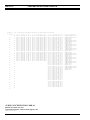
Editor program. From the Editor's "Edit Entity
Database" option, LID and GID entities can be entered
for dispatch operations. Editor program version 3.1x
supports 2000 total entities (LIDs and GIDs) and version 4.x
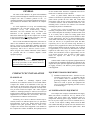
supports a total of 4000 entities.
❏
Refer to the EDACS C3 Maestro Console System
Editor Program user's manual, LBI-39056. Set-up
the required LID and GID entities at each console
via the Editor's "Edit Entity Database"
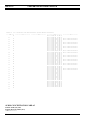
screen. Figure 1 shows a typical screen. Note the
following:
•
•
If a System Manager is present LID and GID
configuration may be performed at the System Manager and
then transferred to the C3 Maestro console(s) using the CEC
Manager's "upload" options.
Site Database
If the EDACS trunked site is equipped with a Site
Controller – for example, an EDACS Level 1 system – and a
System Manager (optional equipment), the site database
stored in the Site Controller may be reconfigured from the
factory default configuration. An EDACS site can be
configured for maximum performance using this method.
8
•
LID and GID numbers are entered in the
"__ID_" column (fields). Entered numbers
must correspond to numbers programmed into
the radio units, other consoles, etc.
In the "TYPE" column, portable, mobile and
desk top station radios are specified by a "U"
for units, conventional channels are specified
by a "C", Call Director patch telephone lines
are specified by a "T" and consoles are
specified by an "X". Talk groups (GID entities)
are specified by a "G".
For units operating on the EDACS trunked site
("TYPE" = "U"), set the home group to "0"
and home site as required via the "HGROUP"
and "HSITE" columns respectively. The home
site number should match the site's "Site ID"
number which should also be equal to the
MIM's site assignment number.
LBI-39117
•
•
•
For each entity, the "PRVLG" (privilege) must
be set to "Y" (Yes) so it may be programmed
into a communication module.
For all entities, set "PVT" (private) to "N"
(No).
If more than one console is employed and
common LID and GID entities are used at
more than one console, the ENTITY.DAT disk
file may be copied from one (source) console
to another (destination) console.
NOTE
NOTE
In a C3 Advantage dispatch system, each unit entity
(LID) may be one of following:
•
•
•
•
•
•
an EDACS portable radio
an EDACS mobile radio
an EDACS desk top station
a C3 Maestro dispatch console
a conventional radio channel
a Call Director patch telephone line
Site Database
In a "System Manager-less" C3 Advantage dispatch
system, the EDACS site's default site database is utilized.
This database is stored in the Site Controller. It defines
various site parameters such as which channel is the initial
control channel, which channels are the initial working
channels, which channels have control channel capability,
channel hang times, etc. If necessary, refer to the EDACS
Site Controller maintenance manual, LBI-38985, for default
values and for additional programming details.
Without a System Manager, a Site Controller's site
database default values can only be modified by removing
PROMs within the Site Controller and returning them to the
factory for reprogramming. Typically, this should not be
required since, in a C3 Advantage dispatch system, the
EDACS site can operate very effectively with the default site
database.
If the EDACS site is not equipped with a Site Controller
no site database exists and therefore no site database
configuration is necessary.
WITH SYSTEM MANAGER
If a System Manager is used with the C3 Advantage
dispatch system, verify the following parameters are set-up
ENTITY.DAT
32128 bytes
09/28/94 12:34:56
F1=Help
All Pvt
Edit
Delete
Sort
Write File Erase DB Pvt
Privilege All Pvlg Find Name Find Next Find ID
Hex Mode
Quit
NUM
0
1
2
3
4
5
6
7
8
9
10
11
.
.
19
__ID_
1234
1240
1285
273
274
289
1
1
2
801
802
803
Units: 1234
TYPE
U
U
U
G
G
G
C
T
T
X
X
X
HGROUP
0
0
0
0
0
0
Groups: 85
HSITE
1
1
1
1
1
1
1
Convs: 4
PRVLG
Y
Y
PVT
Y
Y
Y
Y
Y
Y
Y
Y
Y
Y
Y
Y
Phones: 0
__NAME__
SMITH P
BROWN P
JONES P
N PATROL
S PATROL
E PATROL
FIRE
1
LINE
1
LINE
2
CONS 01
CONS 02
SUPR CON
Consoles: 6
Figure 1 – Editor Program – Edit Entity Database Screen (Typical)
9
LBI-39117
correctly at the System Manager. Refer to the EDACS
System Manager user guide, LBI-38984, and the CEC/IMC
Digital Audio Switch Installation, Set-Up and
Troubleshooting manual, LBI-38938, for additional details:
❏
❏
Group Call Parameters – For each talk group
(GID), enable wide area operation and enable
automatic tracking operation. This ensures a
conventional channel can be patched to the trunked
group. Also, disable the talk group's confirmed call
option. Using the valid site mask field, make the
group valid on the EDACS trunked site (equal to
the MIM site assignment number; normally 1) and
on the conventional "site" (the VMIM site
assignment number; normally 2). The settings in
the forced site mask field are optional.
Individual Call Parameters – For each unit
(LID), disable wide area operation, automatic
tracking and the confirmed call options. Make the
unit valid on the EDACS trunked site (equal to the
MIM site assignment number; normally 1) by
enabling the valid site mask for the trunked site.
Also, each C3 Maestro console and each EDACS
radio should have its home site assignment set to
match the site assignment number (Site ID) of the
EDACS trunked site. In addition, set the home
group assignment for each unit as required.
COMPACT CEC SET-UP
This section summarizes procedures that must be
performed to set-up (configure) the Compact CEC after the
hardware installation is complete. In many cases, to avoid
duplication of information, references are made to
information within the CEC/IMC Digital Audio Switch –
Installation, Set-Up and Troubleshooting manual which is
included with this manual set, LBI-38938.
References are also made to other applicable manuals
including the CEC Manager (MOM PC) operations guide.
Table 2 shows the CEC Manager operations guide
publication numbers for various software versions.
Table 2 – CEC Manager (MOM PC)
Operations Guide Publication Numbers
SOFTWARE
VERSION
V2.1x
V3.0x
V4.0x
PUBLICATION LBI-38911 LBI-39024 LBI-39124
NUMBER
10
NOTE
NOTE
Unless otherwise noted, all set-up procedures in
this manual should be performed in the order
presented.
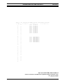
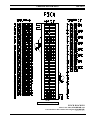
DIP SWITCH CONFIGURATION
DIP switches on all boards in the Compact CEC cabinet
are factory configured for a standard C3 Advantage
installation. Factory settings are shown in the DIP Switch
Settings diagram in this manual. Also, the MIM Controller
Board's factory settings are detailed in Figure 2.
In most cases, little if any changes from the factory
settings will be necessary. However, the following subsections should be reviewed before continuing with the setup process:
Controller Boards
Each Controller Board in the Compact CEC has two 8position DIP switches which are set at the factory in
accordance with the DIP Switch Settings diagram. In a
typical C3 Advantage installation, only one Controller
Board in the Compact CEC switch may require resetting
from the factory setting. This is the MIM Controller Board
which is located in slot 2 of the upper or primary Card Cage
– Card Cage 1. The MIM interfaces the EDACS trunked site
to the Compact CEC.
The MIM Controller Board may need it's "site
assignment number" changed from the factory setting of 1
(decimal) to a number which matches the site's "Site ID"
number. This is, however, a rare instance for the majority of
C3 Advantage installations since most Site Controllers
which ship out from the factory are programmed with a Site
ID number of 1. Reprogramming of a Site Controller's Site
ID number is normally only done at the factory.
If the trunked site is an EDACS Basic system (no Site
Controller), the GETCs' Site ID number may be easily
reprogrammed to 1, if needed, via PC Programming
Software TQ-3357.
NOTE
NOTE
V5.x
(to be
determined)
If the site's Site ID number is changed, all radio
units operating on the EDACS trunked site must be
reprogrammed with a matching Site ID number.
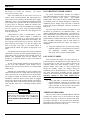
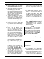
As shown in the DIP Switch Settings diagram and
Figures 2 and 3, SW1 position 5 and SW2 positions 4 thru
8 specify the MIM's site assignment number. See LBI-38938
for complete DIP switch setting information.
LBI-39117
❏
If necessary, change the MIM's site assignment
number to match the site's Site ID number by
setting the binary equivalent at SW1 and SW2.
Figure 3 is an example with the site assignment
number set to 13 (decimal). Again, the factory
setting – site assignment number = 1 – is shown in
Figure 2 and in the DIP Switch Settings diagram.
A Controller Board must be reset after a DIP
switch change.
NOTE
NOTE
(BIT 2 = 16)
(BIT 23 = 8)
(BIT 22 = 4)
(BIT 21 = 2)
SW2
OPEN
MIM SITE ASSIGNMENT
NUMBER LEAST
SIGNIFICANT BIT (20 = 1)
OPEN
OPEN = 1
CLOSED = 0
1
2
3
4
5
6
7
8
1
2
3
4
32
x0
0
5
6
7
8
16
8
4
x0 x0 x0
+0 +0 +0
2
x0
+0
1
x1
+1
= 1 = SITE ASSIGNMENT NUMBER
Figure 2 – MIM Controller Board DIP Switch
Factory Setting (Site Assignment Number = 1)
SW1
SW2
OPEN
OPEN
OPEN = 1
CLOSED = 0
1
2
3
4
5
32
x0
0
6
7
8
1
2
3
4
5
All Audio Boards within the Compact CEC are located
in the upper or primary Card Cage – Card Cage 1. Each
Audio Board has one 8-position DIP switch which allows
configuration of three basic board parameters: board
number, EEPOT board power-up setting, and 2175/8700 Hz
tone selection.
The board number setting sets which group of four (4)
audio channels the board is assigned to and wired for (board
1 = channels 1 - 4; board 2 = channels 5 - 8; etc.).
4
MIM SITE ASSIGNMENT
NUMBER MOST
SIGNIFICANT BIT
(25 = 32)
SW1
If, during servicing/troubleshooting procedures for
example, a Controller Board must be moved to a
different Card Cage slot, its DIP switches should be
set in accordance with the DIP Switch Settings
diagram in this manual for the particular Card Cage
slot which it will be installed within. A Controller
Board must be reset after a DIP switch change.
Audio Boards
If the MIM's site assignment number is changed to
2 (decimal), the VMIM site assignment number
must also be changed from its factory setting of 2
(decimal). The MIM and VMIM site assignment
numbers cannot be identical.
"END NODE" SWITCH MUST BE
OPEN (1) IF THE CONTROLLER
BOARD IS THE END CONTROLLER BOARD IN THE
PRIMARY BACKPLANE
STRUCTURE (COMPACT
CEC CARD CAGE 1).
NOTE
NOTE
6
7
8
16
8
4
x0 x1 x1
+0 +8 +4
2
x0
+0
1
x1
+1
= 13 = SITE ASSIGNMENT NUMBER
Figure 3 – MIM Controller Board DIP Switch
Settings Example (Site Assignment Number = 13)
The EEPOT power-up setting is basically not used since
a Controller Board initializes the EEPOTs on its Audio
Board(s) in accordance with the MOM's configuration. This
occurs at system power-up or if either the Audio or
Controller Board is reset. Essentially, these switches are
only useful for diagnostic procedures when a Controller
Board is not connected to the Audio Board.
The 2175/8700 Hz tone selection must be set to match
the tone frequency sent out from the installed Clock Board.
With the existing Clock Board (19D903305P1), the 2175
Hz tone should always be selected.
At the factory, before installation into the Card Cage,
each Audio Board's 8-position DIP switch is set in
accordance with the DIP Switch Settings diagram in this
manual. Normally, Audio Board DIP switch changes are
never required during the installation and set-up process of a
Compact CEC.
NOTE
NOTE
If, during servicing/troubleshooting procedures for
example, an Audio Board must be moved to a
different Card Cage slot, its DIP switch should be
set in accordance with the DIP Switch Settings
diagram in this manual for the particular Card Cage
slot which it will be installed within.
11
LBI-39117
Conventional Interface Boards
CI Boards within the CIA Card Cage – Card Cage 2 –
have one 8-position DIP switch which allows configuration
of the following board parameters: "site" number, test mode
enable/disable, watchdog timer enable/disable, and board
number.
At the factory, before installation into the Card Cage,
each CI Board DIP switch is set in accordance with the DIP
Switch Settings diagram in this manual (Card Cage 2, slots 3
and 5). Normally, CI Board DIP switch changes are never
required during the installation and set-up process of a
Compact CEC.
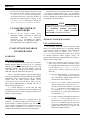
Manual, LBI-38896, for additional details. After any GETC
DIP switch change, the GETC should be reset by pressing
the reset button on its Logic Board.
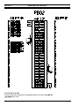
S1
1
2
3
4
5
S2
6
7
8
- - - - - - - - - OPEN - - - - - - - - -
1
2
3
4
5
S3
6
7
8
- - - - - - - - - OPEN - - - - - - - - -
1
2
3
4
5
6
7
8
- - - - - - - - - OPEN - - - - - - - - -
S1-8 = "OPEN".
ALL OTHER SWITCHES "CLOSED".
Figure 4 – Uplink GETC DIP Switch Settings
INITIAL MOM CONFIGURATION
NOTE
NOTE
If, during servicing/troubleshooting procedures for
example, a CI Board must be moved to a different
Card Cage slot, its DIP switch should be set in
accordance with the DIP Switch Settings diagram
in this manual for the particular Card Cage slot
which it will be installed within.
The very first Compact CEC configuration from the
CEC Manager involves setting up CEC Manager users and
several high-level MOM parameters as described in
LBI-38938. Set-up the following parameters in accordance
with LBI-38938:
❏
CEC Manager Users – Enter user names and an
access level and a password for each user.
Afterwards, delete the default user name and
password – "MOMUSER" and "GUEST"
respectively.
❏
MOM Parameters – Set baud rates, disable data
logging, enable or disable printer status, disable
redundant clocks, and disable unit logout timers. If
required, data logging and redundant clocks may be
enabled at a later time; however, these items should
be disabled for the time being.
❏
System Time And Date – Enter the date and time
at the CEC Manager. If the Spectracom
NETCLOCK/2™ equipment (optional) is included,
do not perform the NETCLOCK/2 set-up at this
time.
Uplink GETC
Within the GETC, there are three 8-position DIP
switches. These switches are located on the lower left-hand
side of the GETC's Logic Board. Together with the GETC's
personality programming, they allow the GETC to be
configured for various applications such an uplink, a
downlink, or a station GETC. The GETC in the Compact
CEC is always configured for uplink operation by setting the
DIP switches as shown in Figure 4. Unlike most other
GETC applications, a GETC configured for uplink operation
does not require any personality programming.
❏
As shown in Figure 4, all DIP switches on an
uplink GETC except S1 position 8 should be in the
"CLOSED" or "ON" position. S1 position 8
should be in the "OPEN" or "OFF" position. This
is the factory setting. Verify the GETC's switches
are setting accordingly. If any DIP switch changes
are made, reset the GETC by pressing the reset
button on the Logic Board.
Uplink GETC DIP switch changes from the above
described should never be required unless, for example,
during servicing procedures, a non-uplink configured GETC
is substituted in place of the existing uplink GETC. In this
case, the substitute GETC's DIP switches must be
configured for uplink operation as described in the previous
paragraph before proper uplink operation will occur. In
addition, the substitute GETC's jumpers and cables must
also be configured for uplink operation. See EDACS Site
Downlink & CEC/IMC Uplink GETC Configuration
12
SYSTEM MANAGER UPLOAD
(If Present)
❏
Transfer or "upload" unit, group and site data from
the System Manager to the Compact CEC in
accordance with LBI-38938 and LBI-38911/
LBI-39024/LBI-39124/etc.
TDM BUS AND SLOT CONFIGURATION
From the CEC Manager, set-up TDM bus and slot
parameters as follows. See LBI-38938 for additional details:
❏
TDM Bus Configuration – Configure
Compact CEC for 8-bus Audio Boards.
the
LBI-39117
❏
TDM Slot Configuration – See Table 3 for
recommended TDM bus time slot allocations.
Typically, a console only requires one (1) slot;
however, allocating four (4) slots for each console
as shown in the table will ensure all CIM audio
channels are available when/if Call Director patch
equipment is interfaced to the respective console.
Table 3 – Recommended TDM Bus Time Slot
Configuration For Compact CEC
CEC
COMPACT CEC
MANAGER
INTERFACE
DESIGNATION
MODULE
SLOTS TO
ALLOCATE
"Console 1"
CIM 1
4
"Console 2"
CIM 2
4
"Console 3"
CIM 3
4
"Site 1" (the
EDACS site)
MIM 1
12
"Site 2" (the
conventional
interface)
VMIM 1
8
NOTE
NOTE
Within this manual, the Compact CEC's MIM is
designated as being interfaced with "Site 1" (Site
ID = 1) and the VMIM is designated as being
interfaced with "Site 2". This is not the case if the
respective Controller Board's site assignment
number DIP switch setting has been changed from
the factory setting. See the prior section entitled
"DIP SWITCH CONFIGURATION" for
additional details.
CONSOLE CONFIGURATION
From the CEC Manager, set-up
parameters for the C3 Maestro console(s):
❏
Input And Output Line Levels – Adjust input and
output line levels for all used MIM and VMIM
channels. Note the CI Board used in the CIA rack
has unity gain channels; therefore, a VMIM's input
and output line levels should be set in accordance
with the line levels in to and out of the respective
CI Board's channels.
❏
Channel Control Signalling – Set all MIM
channels' control signalling as required – "M",
"Tone", "Both" or "Off". Set all VMIM
channels "Off".
❏
Confirmed Call – Disable confirmed call
operation on both the MIM "site" and the VMIM
"site".
following
❏
CIM Channels – Configure channel 1 of each
CIM by setting its input level as required and
disable the channel's ALC. Typically, a -5 dBm to
0 dBm input level setting should be sufficient for
the 100-foot (30.5 meters) console-to-Compact
CEC cables supplied with the C3 Advantage
package. If a particular console is equipped with
Call Director patch equipment also set channel
four's (4) input level as required and disable this
channel's ALC. All CIM output levels are
determined by the console's volume bars; they
cannot be changed via the CEC Manager. See
LBI-38938 for additional details.
❏
Console Hardware Configuration – Configure
console hardware related parameters such as the
number of speakers, the number of Audio PA
Boards and the Call Director ID number. See
LBI-38938 and/or LBI-39055/LBI-39101 for
additional details.
RADIO SYSTEM "SITE"
CONFIGURATION
From the CEC Manager, set-up channel parameters for
the Compact CEC's "site"-type interfaces – the MIM for
"Site 1" and the VMIM for "Site 2". Refer to LBI-38938:
the
NOTE
NOTE
The console(s) must be on-line with the Compact
CEC before continuing with the following console
user profile, privilege lists and communication
module build procedures.
❏
Console User Profiles – Configure, save and send
console user profiles as described in LBI-38938.
❏
Console Privilege Lists – If the System Manager is
employed, configure, save and send console
privilege lists as described in LBI-38938. Do not
perform this operation if the C3 Advantage
dispatch system is "System Manager-less".
13
LBI-39117
❏
Set-Up At The Consoles – At each C3 Maestro
console, build communication modules by adding a
unit or group to each module as required. See the
C3 Maestro operator's manual, LBI-38660 (section
ECR-4489) for specific details.
LOGGING RECORDER CONFIGURATION
❏
NOTE
NOTE
At this point in the set-up process, dispatch
communications with radio units logged onto the
EDACS site is possible.
The Compact CEC is equipped with one 8-channel
LRIM. Configure the eight (8) logging recorder
channels by defining "modules" as described in
LBI-38938 and in the CEC Manager operations
guide listed in Table 2. If the C3 Advantage
dispatch system is not equipped with a System
Manager, LID and GID numbers must be entered
with the "#" prefix. See the CEC Manager's
operations guide for details.
NOTE
NOTE
CONVENTIONAL CHANNEL
CONFIGURATION
The Compact CEC may be equipped with up to eight
(8) channels for interfacing to conventional base station
equipment. Each utilized channel should now be configured
as outlined in LBI-38938 and as described in the CEC
Manager operations guide. (See Table 2 in this manual for
CEC Manager operations guide publication numbers.):
❏
VMIM Channel Configuration – Verify the
VMIM's channel parameters have been configured
properly.
❏
Conventional Channel Programming – Program
CI Board low and high-level channel parameters as
required.
❏
VOX Threshold And Secur-It™/Function/2175
Hz Hold Tone Levels – Program CI Board VOX
and tone control tone signalling levels as required.
❏
❏
System Manager Database Upload – If a System
Manager is employed, perform a CEC Managerbased (MOM PC-based) System Manager database
upload.
Console Updating – Now, "build" or "modify"
each console's communication module(s) by adding
conventional channel(s) as required.
NOTE
NOTE
At this point in the set-up process, dispatch
communications with the conventional channel(s) is
possible. This assumes the applicable conventional
base station(s) are operating, configured, linked to
the Compact CEC and conventional channel(s)
have been programmed into communications
modules at the console(s). Also, conventional
channel patch should also be operational.
14
At this point in the set-up process, logging recorder
audio is available at the LRIM's line outputs.
AUXILIARY I/O CONFIGURATION
❏
Any of the installed Controller Boards in the
Compact CEC's upper Card Cage may be used for
auxiliary I/O control. If any auxiliary I/O functions
are needed, refer to LBI-38938 for wiring and setup information. Installation details for auxiliary I/O
option MSDE3U are included in LBI-38938. Also
see the CEC Manager operations guide. (See Table
2 in this manual for CEC Manager operations guide
publication numbers.)
NOTE
NOTE
At this point in the set-up process, the auxiliary I/O
lines will operate as wired and configured.
WWVB TIME STANDARD
CONFIGURATION
If the Spectramcom NETCLOCK/2™ equipment
(optional) is included with the C3 Advantage package, time
display at the C3 Maestro console(s) and error/warning
logging time stamps at the CEC Manager may be
synchronized to WWVB's time broadcasts. WWVB is
located in Fort Collins, Colorado. The NETCLOCK/2™
option is interfaced to the Compact CEC via the CEC
Manager.
❏
If the Spectramcom NETCLOCK/2™ option is
included, it should now be installed and configured.
Refer to LBI-38938 and the CEC Manager
operations guide. (See Table 2 in this manual for
CEC Manager operations guide publication
numbers.)
LBI-39117
NOTE
NOTE
At this point in the set-up process, if the
NETCLOCK/2™ option is enabled, time display at
the console(s) and error/warning logging time
stamps at the CEC Manager will be synchronized
to WWVB.
REDUNDANT CLOCK CONFIGURATION
❏
If back-up clocking is desired, this option must be
activated by enabling it from the CEC Manager's
"MOM Configuration" screen.
NOTE
NOTE
When only one Clock Board is installed in the
Compact CEC, both toggle switches – "A" and "B"
on the front of the board – must be turned on before
redundant clock operation is possible.
The Compact CEC is factory-equipped with one (1)
Clock Board which has redundant (back-up) clock circuits.
These circuits provide clock pulse timing signals for the
Audio Boards' TDM bus circuits across the upper Card Cage
(Card Cage 1). The lower Card Cage (the CIA rack – Card
Cage 2) does not require and is not equipped with any Clock
Boards.
15
LBI-39117
CABLE INTERCONNECTIONS
Figure 5 – Card Cage 1, Slots 1 - 5 (MIM)
16
CABLE INTERCONNECTIONS
LBI-39117
Figure 6 – Card Cage 1, Slots 6 - 11 (CIM 1 - 3)
17
LBI-39117
CABLE INTERCONNECTIONS
Figure 7 – Card Cage 1, Slots 12 - 14 (LRIM)
18
CABLE INTERCONNECTIONS
LBI-39117
Figure 8 – Card Cage 1, Slots 15 - 17 (VMIM) And Card Cage 2 (CIA Rack), Slots 2, 3 and 5 (CCI and CI Boards)
19
LBI-39117
CABLE INTERCONNECTIONS
Figure 9 – Card Cage 1, Slots 18 - 21 (MOM)
20
DIP SWITCH SETTINGS
LBI-39117
COMPACT CEC CONTROLLER BOARD AND
AUDIO BOARD DIP SWITCH SETTINGS
(188D6170, Sh. 2, Rev. 1)
21
LBI-39117
Cabinet 01
CONCENTRATOR CARD PIN-OUTS
A01
---- PINS ---26
01
27
02
28
03
29
04
30
05
31
06
32
07
33
08
34
09
35
10
36
11
37
12
38
13
39
14
40
15
41
16
42
17
43
18
44
19
45
20
46
21
47
22
48
23
49
24
50
25
Concentrator Card AUDIO Connections (To/From External Connections)
------------J07----------SYS 01 AUDIO IN LO LN 01
SYS 01 AUDIO IN HI LN 01
SYS 01 AUDIO IN LO LN 02
SYS 01 AUDIO IN HI LN 02
SYS 01 AUDIO IN LO LN 03
SYS 01 AUDIO IN LO LN 03
SYS 01 AUDIO IN HI LN 04
SYS 01 AUDIO IN LO LN 04
SYS 01 AUDIO IN HI LN 05
SYS 01 AUDIO IN LO LN 05
SYS 01 AUDIO IN HI LN 06
SYS 01 AUDIO IN LO LN 06
SYS 01 AUDIO IN HI LN 07
SYS 01 AUDIO IN LO LN 07
SYS 01 AUDIO IN HI LN 08
SYS 01 AUDIO IN LO LN 08
SYS 01 AUDIO IN HI LN 09
SYS 01 AUDIO IN LO LN 09
SYS 01 AUDIO IN HI LN 10
SYS 01 AUDIO IN LO LN 10
SYS 01 AUDIO IN HI LN 11
SYS 01 AUDIO IN LO LN 11
SYS 01 AUDIO IN HI LN 12
SYS 01 AUDIO IN LO LN 12
------------J08----------SYS 01 AUDIO OUT LO LN 01
SYS 01 AUDIO OUT HI LN 01
SYS 01 AUDIO OUT LO LN 02
SYS 01 AUDIO OUT HI LN 02
SYS 01 AUDIO OUT LO LN 03
SYS 01 AUDIO OUT HI LN 03
SYS 01 AUDIO OUT LO LN 04
SYS 01 AUDIO OUT HI LN 04
SYS 01 AUDIO OUT LO LN 05
SYS 01 AUDIO OUT HI LN 05
SYS 01 AUDIO OUT LO LN 06
SYS 01 AUDIO OUT HI LN 06
SYS 01 AUDIO OUT LO LN 07
SYS 01 AUDIO OUT HI LN 07
SYS 01 AUDIO OUT LO LN 08
SYS 01 AUDIO OUT HI LN 08
SYS 01 AUDIO OUT LO LN 09
SYS 01 AUDIO OUT HI LN 09
SYS 01 AUDIO OUT LO LN 10
SYS 01 AUDIO OUT HI LN 10
SYS 01 AUDIO OUT LO LN 11
SYS 01 AUDIO OUT HI LN 11
SYS 01 AUDIO OUT LO LN 12
SYS 01 AUDIO OUT HI LN 12
AUDIO CONCENTRATOR CARD A1
EDACS Site Audio (J9) And
Conventional 2/4-Wire Audio/Control Signals (J10)
(350A1261, Sh. 12 & 13, Rev. 1)
22
------------J09-----------SYS 01 AUDIO IN LO LN 01
SYS 01 AUDIO IN HI LN 01
SYS 01 AUDIO OUT LO LN 01
SYS 01 AUDIO OUT HI LN 01
SYS 01 AUDIO IN LO LN 02
SYS 01 AUDIO IN HI LN 02
SYS 01 AUDIO OUT LO LN 02
SYS 01 AUDIO OUT HI LN 02
SYS 01 AUDIO IN LO LN 03
SYS 01 AUDIO IN HI LN 03
SYS 01 AUDIO OUT LO LN 03
SYS 01 AUDIO OUT HI LN 03
SYS 01 AUDIO IN LO LN 04
SYS 01 AUDIO IN HI LN 04
SYS 01 AUDIO OUT LO LN 04
SYS 01 AUDIO OUT HI LN 04
SYS 01 AUDIO IN LO LN 05
SYS 01 AUDIO IN HI LN 05
SYS 01 AUDIO OUT LO LN 05
SYS 01 AUDIO OUT HI LN 05
SYS 01 AUDIO IN LO LN 06
SYS 01 AUDIO IN HI LN 06
SYS 01 AUDIO OUT LO LN 06
SYS 01 AUDIO OUT HI LN 06
SYS 01 AUDIO IN LO LN 07
SYS 01 AUDIO IN HI LN 07
SYS 01 AUDIO OUT LO LN 07
SYS 01 AUDIO OUT HI LN 07
SYS 01 AUDIO IN LO LN 08
SYS 01 AUDIO IN HI LN 08
SYS 01 AUDIO OUT LO LN 08
SYS 01 AUDIO OUT HI LN 08
SYS 01 AUDIO IN LO LN 09
SYS 01 AUDIO IN HI LN 09
SYS 01 AUDIO OUT LO LN 09
SYS 01 AUDIO OUT HI LN 09
SYS 01 AUDIO IN LO LN 10
SYS 01 AUDIO IN HI LN 10
SYS 01 AUDIO OUT LO LN 10
SYS 01 AUDIO OUT HI LN 10
SYS 01 AUDIO IN LO LN 11
SYS 01 AUDIO IN HI LN 11
SYS 01 AUDIO OUT LO LN 11
SYS 01 AUDIO OUT HI LN 11
SYS 01 AUDIO IN LO LN 12
SYS 01 AUDIO IN HI LN 12
SYS 01 AUDIO OUT LO LN 12
SYS 01 AUDIO OUT HI LN 12
------------J10------SIMPLX/DUPLEX OUT L1
SIMPLX/DUPLEX OUT H1
DUPLEX IN L1
DUPLEX IN H1
SIMPLX/DUPLEX OUT L2
SIMPLX/DUPLEX OUT H2
DUPLEX IN L2
DUPLEX IN H2
SIMPLX/DUPLEX OUT L3
SIMPLX/DUPLEX OUT H3
DUPLEX IN L3
DUPLEX IN H3
SIMPLX/DUPLEX OUT L4
SIMPLX/DUPLEX OUT H4
DUPLEX IN L4
DUPLEX IN H4
SIMPLX/DUPLEX OUT L5
SIMPLX/DUPLEX OUT H5
DUPLEX IN L5
DUPLEX IN H5
SIMPLX/DUPLEX OUT L6
SIMPLX/DUPLEX OUT H6
DUPLEX IN L6
DUPLEX IN H6
SIMPLX/DUPLEX OUT L7
SIMPLX/DUPLEX OUT H7
DUPLEX IN L7
DUPLEX IN H7
SIMPLX/DUPLEX OUT L8
SIMPLX/DUPLEX OUT H8
DUPLEX IN L8
DUPLEX IN H8
CONCENTRATOR CARD PIN-OUTS
Cabinet 01
A02
---- PINS ---26
01
27
02
28
03
29
04
30
05
31
06
32
07
33
08
34
09
35
10
36
11
37
12
38
13
39
14
40
15
41
16
42
17
43
18
44
19
45
20
46
21
47
22
48
23
49
24
50
25
LBI-39117
Concentrator Card CONTROL Connections (To/From External Connections)
-------J11-------
---------J12--------CRT 01
TX- DATA 422
CRT 01
TX+ DATA 422
CRT 01
RX- DATA 422
CRT 01
RX+ DATA 422
CRT 02
TX- DATA 422
CRT 02
TX+ DATA 422
CRT 02
RX- DATA 422
CRT 02
RX+ DATA 422
CRT 03
TX- DATA 422
CRT 03
TX+ DATA 422
CRT 03
RX- DATA 422
CRT 03
RX+ DATA 422
SYS
SYS
SYS
SYS
SYS
SYS
SYS
SYS
01
01
01
01
01
01
01
01
UPLNK0
UPLNK0
UPLNK0
UPLNK0
UPLNK1
UPLNK1
UPLNK1
UPLNK1
MODEM
MODEM
MODEM
MODEM
MODEM
MODEM
MODEM
MODEM
----------J13---------
TX
TX
RX
RX
TX
TX
RX
RX
+
+
+
+
DATA CONCENTRATOR CARD A2
Console Control Data And EDACS Site Uplink/Downlink Control Data (J12)
(J11 & J13 Not Used)
(350A1261, Sh. 16 & 17, Rev. 1)
23
LBI-39117
Cabinet 01
CONCENTRATOR CARD PIN-OUTS
A03
---- PINS ---26
01
27
02
28
03
29
04
30
05
31
06
32
07
33
08
34
09
35
10
36
11
37
12
38
13
39
14
40
15
41
16
42
17
43
18
44
19
45
20
46
21
47
22
48
23
49
24
50
25
Concentrator Card AUDIO Connections (To/From External Connections)
------------J07-----------
------------J08-----------
AUDIO CONCENTRATOR CARD A3
Console Audio (J9) And
Logging Recorder Audio (J10)
(350A1261, Sh. 14 & 15, Rev. 1)
24
------------J09----------CRT 01 AUDIO IN LO LN 01
CRT 01 AUDIO IN HI LN 01
CRT 01 AUDIO OUT LO LN 01
CRT 01 AUDIO OUT HI LN 01
CRT 01 AUDIO IN LO LN 02
CRT 01 AUDIO IN HI LN 02
CRT 01 AUDIO OUT LO LN 02
CRT 01 AUDIO OUT HI LN 02
CRT 01 AUDIO IN LO LN 03
CRT 01 AUDIO IN HI LN 03
CRT 01 AUDIO OUT LO LN 03
CRT 01 AUDIO OUT HI LN 03
CRT 01 AUDIO IN LO LN 04
CRT 01 AUDIO IN HI LN 04
CRT 01 AUDIO OUT LO LN 04
CRT 01 AUDIO OUT HI LN 04
CRT 02 AUDIO IN LO LN 01
CRT 02 AUDIO IN HI LN 01
CRT 02 AUDIO OUT LO LN 01
CRT 02 AUDIO OUT HI LN 01
CRT 02 AUDIO IN LO LN 02
CRT 02 AUDIO IN HI LN 02
CRT 02 AUDIO OUT LO LN 02
CRT 02 AUDIO OUT HI LN 02
CRT 02 AUDIO IN LO LN 03
CRT 02 AUDIO IN HI LN 03
CRT 02 AUDIO OUT LO LN 03
CRT 02 AUDIO OUT HI LN 03
CRT 02 AUDIO IN LO LN 04
CRT 02 AUDIO IN HI LN 04
CRT 02 AUDIO OUT LO LN 04
CRT 02 AUDIO OUT HI LN 04
CRT 03 AUDIO IN LO LN 01
CRT 03 AUDIO IN HI LN 01
CRT 03 AUDIO OUT LO LN 01
CRT 03 AUDIO OUT HI LN 01
CRT 03 AUDIO IN LO LN 02
CRT 03 AUDIO IN HI LN 02
CRT 03 AUDIO OUT LO LN 02
CRT 03 AUDIO OUT HI LN 02
CRT 03 AUDIO IN LO LN 03
CRT 03 AUDIO IN HI LN 03
CRT 03 AUDIO OUT LO LN 03
CRT 03 AUDIO OUT HI LN 03
CRT 03 AUDIO IN LO LN 04
CRT 03 AUDIO IN HI LN 04
CRT 03 AUDIO OUT LO LN 04
CRT 03 AUDIO OUT HI LN 04
------------J10----------RIF 01
RIF 01
AUDIO OUT LO LN 01
AUDIO OUT HI LN 01
RIF 01
RIF 01
AUDIO OUT LO LN 02
AUDIO OUT HI LN 02
RIF 01
RIF 01
AUDIO OUT LO LN 03
AUDIO OUT HI LN 03
RIF 01
RIF 01
AUDIO OUT LO LN 04
AUDIO OUT HI LN 04
RIF 01
RIF 01
AUDIO OUT LO LN 05
AUDIO OUT HI LN 05
RIF 01
RIF 01
AUDIO OUT LO LN 06
AUDIO OUT HI LN 06
RIF 01
RIF 01
AUDIO OUT LO LN 07
AUDIO OUT HI LN 07
RIF 01
RIF 01
AUDIO OUT LO LN 08
AUDIO OUT HI LN 08
PUNCH BLOCK PIN-OUTS
LBI-39117
NOTE
DO NOT install bridging clips.
PUNCH BLOCK PB1
EDACS Site Audio (COLUMN AB) And
Conventional 2/4-Wire Audio/Control Signals (COLUMN CD)
(188D6170, Sh. 5, Rev. 1)
25
LBI-39117
PUNCH BLOCK PIN-OUTS
PUNCH BLOCK PB2
Console Control Data And EDACS Site Uplink/Downlink Control Data (COLUMN AB)
(COLUMN CD Not Used)
(188D6170, Sh. 5, Rev. 1)
26
PUNCH BLOCK PIN-OUTS
LBI-39117
NOTE
DO NOT install bridging clips.
PUNCH BLOCK PB3
Console Audio (COLUMN AB) And
Logging Recorder Audio (COLUMN CD)
(188D6170, Sh. 5, Rev. 1)
27
Ericsson Inc.
Private Radio Systems
Mountain View Road
Lynchburg, Virginia 24502
1-800-528-7711 (Outside USA, 804-528-7711)
Printed in U.S.A.