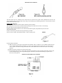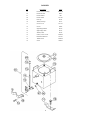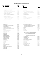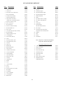
1
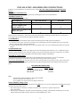
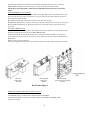
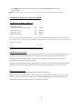
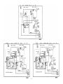
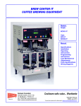
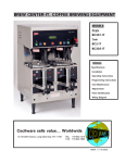
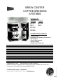
BREW CENTER
COFFEE BREWING
SYSTEMS
MODEL #'s_____
Singles Twins
BC301
BC302
BC1
BC2
BC120
BC240
OPERATION MANUAL
Specifications
Installation & Operating Instructions
Adjustments
Care & Maintenance
Wiring Diagram
Replacement Parts List
SPECIFICATIONS
CAPACITY:
Cups/Brew Cycle
Cups/Hour
ELECTRICAL DATA:
Volts
Watts
Amps
DIMENSIONS (Inches)
Height*
Width
Depth
Ship Weight (Ibs.)
BC120
Selective
12/24
120
BC240
Selective
12/24
200
BC1
BC2
2x36
400
BC301
Selective
12/24/36
240
BC302
Selective
12/24/36
400
1 x36
240
120
1800
15
120/240
3120
13
120/240
4120
18
120/240
6230
27
120/240
4140
18
120/240
6280
27
31
9
1
20 /2
65
31
9
1
20 /2
65
31
9
1
20 /2
65
31
18
1
20 /2
110
31
9
1
20 /2
65
31
18
1
20 /2
110
*Height includes 4" legs.
All units require 3/8” water connection.
All Brew Centers are single phase with 3 wires plus a ground; except BC120 is 120V, with
cord and plug, 15 Amp wall outlet required (NEMA #5-15R).
Cecilware Sells Value...Worldwide
43-05 20th Avenue, Long Island City, NY 11105
(718) 932-1414
Fax: (718) 932-7860
.
INSTALLATION AND OPERATING INSTRUCTIONS
Warranty is void if the Brewer is connected to any voltage other than voltage specified on the data label of the
Brewer.
UNPACKING AND INSPECTION
Carefully unpack the Brewer by cutting the straps and lifting the sleeve carton off the Brewer.
ASSEMBLY AND SET-UP
The Brewer is shipped complete with:
DESCRIPTION
BC1,120,240,301
BC2,302
4
4
1
2
1
2
Adjustable legs
Carriers complete with
Faucets and Covers
Funnels with wire baskets and
sample filter pack
Remove carriers from Brewer, one has the four (4) legs packed inside. Install legs by tilting Brewer on it's back and
screwing the legs into the threaded leg support openings on bottom.
WATER HOOK UP
The National Sanitation Foundation (NSF) requires the following for the NSF approved installation:
1. A quick disconnect water connection or enough extra coiled tubing (at least 2x the depth of the unit) so that the
Brewer can be moved for cleaning underneath.
2. An approved flow-back prevention device such as a double check valve to be installed between Brewer and water
supply.
WATER CONNECTION
The Brewer comes equipped with a 3/8 compression water inlet fitting located in the back. Use a 3/8 diameter copper
tubing to connect the Brewer to a cold water supply, water pressure should be 20 psi min. to 80 psi max. An external
shut-off valve and a water filtering system with a charcoal filter is highly recommended.
ELECTRICAL CONNECTIONS
A terminal block inside the base compartment is provided for electrical connections. Two (2) 3 /l6" diameter
openings for field conduit connections are provided in the bottom and the back of the base.
To access the Terminal Block, loosen the 2 screws on the side of the base cover and remove the 1 lower screw at the
base of the rear panel. Dis -engage base panel from rear panel by lifting base panel up and lifting back towards rear
panel.
RECOMMENDED WIRING SIZES
Model No.
Single (1) Phase
BC1, BC120, BC240, BC301
BC2, BC302
12 AWG
10 AWG
Note:
1. Neutral (N) and Ground Wires to be 14 AWG minimum.
2. Field wiring must be suitable for 75° C.
3. Use Copper wire only for all power supply connections.
INITIAL PRIMING - Filling of Tank
The BC Brewers are shipped with the Thermostat in the OFF position. Do not turn Thermostat to the ON position until
the Brewer has been fully primed.
1. Turn water supply on and check for leaks at the water inlet connections. Tighten compression
fitting if necessary.
2. Turn on power to the Brewer. The Brewer will automatically start filling. After 6 minutes the filling cycle will stop
and the thermostat should be turned clockwise to the full ON position. Allow
2
approximately 20 minutes for the brewer to reach full brewing temperature (197°-203°). When the
GREEN READY LIGHT comes ON the brewer is ready to brew the next batch of coffee.
NOTE: Before proceeding further, make sure the sample filter pack has been removed from the
funnel.
CHECKING BREW CYCLE OUTPUTS.
The BC-Series brewers are factory preset to deliver the proper amount of brewing water for the 12 cup,
24 cup and 36 cup brew cycles. Nevertheless, it is a good practice to check the output levels prior to
brewing the first batch of coffee.
BC1 and BC2: Full 36 cups (3 decanters) per brew cycle with a 20% by-pass.
BC120 and BC 240: Selectively 12 cups (1 decanter) or 24 cups (2 decanters) per brew cycle. No by-pass.
BC301 and BC302: Selectively 12, 24 and 36 cups per brew cycle with a 20% by-pass for the 36 cup
cycle only.
TO START A BREW CYCLE:
Turn Warmer Switch to the ON position. The Warmer Switches also double as CYCLE STOP switches.
With Funnel and Carrier in place activate GREEN BREW switch.
On BC120, BC240, BC301 and BC302 brewers first activate brew switches marked 12 cups and then
check output. Do the same with the 24 cup brew switch and the 36 cup brew switch for the BC301 and
BC302 units.
NOTE: 12 cups equal 1 full decanter.
If necessary adjust the timer(s) to increase or decrease output levels. See Timer adjustment procedure.
BC1, BC2
Single Timer
(L264A)
BC120, BC240
Dual Timer
(58026)
BC301, BC302
Triple Timer (Dual Voltage)
(L410A)
Brew Timers Figure 1
TIMER ADJUSTMENT PROCEDURE. (Refer to Figure 1)
Remove the top cover to access the brew timer(s).
To INCREASE output: turn timer knob a small increment CLOCKWISE.
To DECREASE output: turn timer knob a small increment COUNTER-CLOCKWISE. Check
output level in carrier.
3
COFFEE BREWING INSTRUCTIONS
Place filter paper into brew basket and add recommended amounts of finely ground coffee as per chart below:
#CUPS
BREWED
RECOMMENDED
COFFEE AMOUNT
TOTAL BREW
TIME
BC1
36 Cups
6 oz.
6.0 Minutes
BC2
36 Cups
6 oz.
6.0 Minutes
BC120
12 Cups
2oz.
3.0 Minutes
BC240
24 Cups
4 oz.
4.5 Minutes
BC301
and
BC302
12 Cups
24 Cups
36 Cups
2oz.
4 oz.
6 oz.
3.0 Minutes
4.5 Minutes
6.0 Minutes
MODEL #
Insert brew funnel back into brewer and position empty carriers under brew funnels. With Warmer
Switches on (lit), depress Green Brew Switches. Total brew time will vary according to cups selected. After funnel
stops dripping, remove and empty funnels.
Warning: Remove Brew funnel ONLY after it has stopped dripping.
BY-PASS Flow Adjustments (See figure 2)
Depending on the model number, the BC Brewers have been factory set to brew 12, 24 and/or 36 cups of coffee, with
the BY-PASS adjusted for a 20% BY-PASS flow of brewing water for the 36 cup, brew output only. Since water
hardness, the brand of coffee, and the length of brew time are important factors in final drink taste, it may be necessary
to adjust the percentage of BY-PASS. In general, the more ground coffee used for each brew, the higher the
percentage of BY-PASS. Proceed as follows to adjust BY-PASS.
1.
2.
3.
4.
Place empty carrier without cover under brew funnel.
Pull brew funnel out 3 inches, exposing BY-PASS outlet behind funnel.
Activate warmer/cycle stop switch. Switch will be lit.
Hold measuring cup under BY-PASS outlet and activate Green Brew Switch. After 15 seconds, push warmer/cycle
stop switch to stop cycle.
5. Measure ounces of water in cup and ounces of water in carrier. Divide ounces in cup by total volume dispensed
(add ounces in cup and carrier) to get the BY-PASS ratio.
4
6. To get more BY-PASS, turn slotted adjustment screw in spray-head adjuster (Item 49 in parts list) counterclockwise. Turning adjuster screw clockwise will decrease the BY-PASS flow.
SPRAY-HEAD ADJUSTER
Left (K245A)
Right (K244A)
BC 2, BC302
(K253A)
BC1, BC301
FIGURE 2
The BC310 and BC302 units do not use a BY-PASS for 12 and 24 cup brewing. The BY-PASS valve is activated only
when the 36 cup cycle is selected. The BC210 and BC240 models only brew 12 or 24 cups and therefore do not use a BYPASS.
THERMOSTAT ADJUSTMENT (See Figure 3)
The BC Brewers are factory set to deliver hot brewing water at 200° F (96° C) when the thermostat knob
is turned on to the full ON position.
THERMOSTAT
BC1, BC2, BC240,
BC301, BC302
BC120
Figure 3
The water temperature, at the spray head, should be between 195° F-2030 F with the thermostat knob at its maximum
clockwise position. If adjustment is necessary, proceed as follows:
1. To RAISE water temperature, turn temperature control knob to its maximum clockwise position. Remove the knob and
locate slotted adjustment screw inside hollow thermostat shaft. Using a narrow-bladed screwdriver, engage slotted
adjustment screw and turn it 1/4 turn counter-clockwise. The thermostat will cut in and the Green ready light will go
off. When Green ready light comes on after a few minutes, measure temperature and repeat if necessary.
5
2. To LOWER water temperature, simply turn knob one notch counter-clockwise to next lower
number on dial.
HINT: To measure water temperature accurately, remove the spray-head for a solid water stream.
SOLID STATE WATER LEVEL CONTROL AND PROBE
WATER LEVEL CONTROL OPERATION
Components involved:
1. Solid state water level control board
Part
#L398A
2. Water inlet valve
Pan
# L397A
3. Water level probe
Part
#K213A
4. Hi-level float switch
Part
#L380A
Under normal conditions and operation, the water level in the lank should not drop more than 1/2" from the
probe. If it does, the tank is not being re-filled fast enough. Check the water line and water filter, they may need
cleaning or replacing.
PROBLEM: NO WATER IS GOING TO THE TANK AT ALL!
WATER INLET VALVE TEST
Turn power off. If the water level rises inside the heating tank, the water inlet valve is leaking. Disconnect wires
from the water inlet valve coil and connect a 2 wire lamp cord to the terminals. Plug it into a 115V outlet. If
water flows in and stops when you pull it out, the valve is working fine. Repeat this test a few times. The
problem may be in the probe or water level board.
If the water does not flow in when the cord is plugged into an electrical outlet, the solenoid coil may be burned,
opened or the valve may have been an obstruction preventing the water from flowing in. Clean or replace it.
Hl-LEVEL FLOAT SWITCH
For BC2 and BC302 units with hinged Hi-level Float Switches, (See figure 4a)
Remove tank cover and check position of Hi-Level float switch inside tank. The hinged part of the float switch
must face up as shown in Figure 4a. The BC1, BC120, BC240, and BC302 units have ball type level detectors
as illustrated in Figure 4b; the ball resting on the retaining clip is shown.
6
HI-LEVEL FLOAT SWITCH
The float switch acts as a guardian for the solid state level control and its probe. If they malfunction and cause the
water inside the tank to rise, the float switch will prevent flooding by terminating the power to the solid state control
board and the water inlet valve.
PROBE TEST (Figure 5)
If lack of water conditions remain the same, check the probe as follows:
Turn on the power to the brewer. Check inside the heating tank to make sure the water is not touching
the probe. Pull wire and terminal out of the probe rod.
If water still does not flow after the wire is disconnected from the probe, the problem may be in the solid
state water level board.
If water starts flowing into the tank, the probe may be grounded
due to excessive liming. Check with Ohm meter. Clean or replace probe.
PROBE
Check the board as follows:
A) Make sure there is power input to the board at the terminals 2 & 3, see Figure 6. Your voltmeter should read 115
volts. It should read the same at terminals 1 & 3. This is the output power to electrify the coil of the solenoid
valve to open it. The lack of voltage at terminals 2 & 4 will indicate that the water level board is not working
properly.
B) Make sure all wire connections to the board are tight.
C) The grounding plate at the top, in the back of the board, should be securely grounded. The board will not work,
or will work erratically, if it is not grounded properly. If after this, the board is still failing to open the water
inlet valve, then replace it.
SOLID STATE WATER LEVEL CONTROL
7
PROBLEM; WATER WILL NOT "STOP" FLOWING INTO THE HEATING TANK
Follow the same procedure as above but in reverse order. Check the Water Level Probe, Solenoid and level controls.
WATER INLET VALVE TEST (FIGURE 7)
Turn off all power to the brewer. Observe the water level inside the heating tank. If it rises, the water inlet valve is
leaking. Rebuild using Valve kit #99371 or replace inlet valve.
REPLACEMENT KITS
WATER INLET VALVE
DUMP VALVE & BY-PASS VALVE
1 - Coil, 120V - Part #X008A
1 - Coil, 120V – Part #CA39A
Coil, 240V - Part #C223A
Coil, 220V – Part #CA38A
2 - Valve Kit - Part #99371
2 - Valve Kit - Part #X079A
a) Guide
c) Armature
a) Spring
b) Spring
d) Diaphragm
b) Diaphragm
c) Plunger
PROBLEM: SPRAY-HEAD WILL NOT STOP DRIPPING OR RUNNING
DUMP VALVE TEST (Figure 8)
Turn off all power to the Brewer. If dripping or running continues, replace naive plunger, spring and diaphragm
using Valve Kit #X079A or simply replace with new dump valve.
8
CARRIER
Fig.
Description
Part#
65
Faucet Shank Assembly
994461X
66
67
Faucet Hex Nut
Faucet Washer
03067
7227
68
Faucet Guard
U812A
69
70
End Cap
Washer, Endvap
38314
38317
71
Carrier Cover
U811A
72
73
Carrier
Sight Gauge Shield
97208
38316
74
Sight Gauge Glass
38315
75
76
Washer, Base
Gasket, Cover Carrier
77
Hold Down Bracket
U833A
78
79
Thumb Screw
Screw
M299A
P808A
9
38318
M294A
BC1, BC120, BC240, BC301 PARTS LIST
FIG. #
DESCRIPTION
PART#
FIG .#
1
90 Degree Elbow
K021A
DESCRIPTION
2
Thermostat Knob
M008A
45
Ballast 120V
CA33A
3
Double Pole Thermostat (BC1, BC240, BC301)
L029A
46
Hi-Limit Switch
M060A
PART#
*Single Pole Thermostat (BC120)
L266A
47
Grommet
M090A
4
Water Inlet Valve 1 GPM 120V
L397A
48
Ground Lug
B081A
5
Heater 4000W/240V (BC240, BC301, BC1)
G044A
49
Spray-Head Adjuster (BC1, BC301)
K253A
*Heater 1700W/120V (BC120)
G045A
*Spray Head Adjuster (BC120, BC240)
K282A
6
Overflow Tube Assembly
H024A
50
Tank Bracket
U856A
7
Indicator Light (BC120, BC240, BC301)
32004
51
Washer Red Silicon
M197A
8
Single Timer, 120V (BC1)
L264A
52
Gasket
M121A
*Dual Timer, 120V (BC120, BC240)
58026
53
Top Warmer Cover Assembly
R615A
*Triple Timer, 120V (BC301)
L410A
54
Silicon Tubing (BC301)
M319A
9
Water Level Sensor, 120V
L398A
55
Screw
P811A
10
Water Tank Cover
U801A
56
Tank Gasket
M289A
11
Hi-Level Float Switch
E003A
57
By-Pass Reducer
H218A
12
Water Level Probe Assembly
K213A
*By-Pass Reducer (BC301)
H221A
13
Hose Barb Elbow 3/8"
K270A
58
Fuse 6 Amps
C395A
14
Water Tank
R617A
59
Logo Plate Fresh Coffee (BC1)
N819A
15
Tower, Base and Top Wrap Assembly
N/A
*Logo Plate Fresh Coffee (BC120, BC240)
N829A
16
Hose Barb Elbow
K246A
*Logo Plate Fresh Coffee (BC301)
N822A
17
Flanged Coupling 1/4 NPT
K275A
60
Wingnut
P810A
19
Power Switch (BC120, BC240, BC301)
L389A
61
Hose
M313A
20
Faucet
D067A
62
Funnel
97502
21
Green Brew Switch, 120V
L383A
63
Wire Basket
75057
22
Heat Switch, 120V
155A
23
Lock Nut
E007A
Note -All parts are common to all machines
24
Spray Cup
E084A
except where listed in description
25
Ready Light
CA34A
26
Hold Down Bracket
U860A
30
Light Component Kit
44431
4
1 GPM Solenoid
L426A
31
Clear Plastic Panel
U907A
8
Single Timer (BC1)
L263A
32
Dump Valve, 120V
80240
9
Level Control
L399A
33
Lock Nut
K048A
19
Power Switch (BC240, BC301)
L424A
34
Toggle Switch
L069A
21
Green Brew Switch
L401A
35
Washer
P072A
22
Heat Switch
L155A
36
Screw
P050A
32
Dump Valve
80249
37
Clip
P126A
40
Warmer Element 100W
G107A
38
Dump Valve Bracket
U857A
45
50Hz Ballast (BC1)
C045A
39
Hexnut
P026A
*60Hz Ballast (BC1)
C046A
40
Warmer Element 120V/100W
G108A
41
Heat Shield
U485A
42
Fuse Holder
C396A
43
Legs 4" Adjustable
M005A
44
Terminal Block
B083A
220V/240V Components For Export
10
11
BC2 AND BC302 PARTS LIST
FIG. #
DESCRIPTION
PART#
FIG.#
1
90 Degree Elbow
K021A
46
Hi-Limit Switch
DESCRIPTION
PART #
M060A
2
Thermostat Knob
M008A
47
Grommet
M090A
3
Thermostat
L029A
48
Ground Lug Copper
B091A
4
Water Inlet Valve 1 GMP 120V
L397A
49
Spray-Head Adjuster, Right
K244A
5
Heater 3000W/240V
G022A
50
Spray-Head Adjuster, Light
K245A
6
Overflow Tube Assembly
H024A
51
Washer Red Silicon
M197A
7
Indicator Light (BC302)
32004
52
Gasket
M121A
8
Single Timer, 120V (BC2)
L264A
53
Top Warmer Glove Assembly
R590A
*Triple Timer, 120V/240V (BC301)
L410A
54
3/8" Silicon Tubing (BC302)
M319A
9
Water Level Sensor, 120V
L398A
55
Screw
P811A
10
Water Tank Cover
U801A
56
Tank Gasket
M289A
11
Hi-Level Switch
L380A
57
By-Pass Reducer
H218A
12
Water Level Probe Assembly
K213A
*By-Pass Reducer (BC302)
H221A
13
Hose Barb Elbow 3/8"
K270A
58
Fuse 6 Amps
C395A
14
Water Tank
R556A
59
Logo Plate Fresh Coffee (BC2)
N815A
15
Tower, Base and Top Wrap Assembly
N/A
*Logo Plate Fresh Coffee (BC302)
N823A
16
Hose Barb Elbow
K246A
60
Wingnut
P810A
17
Flanged Coupling 1/4 NPT
K275A
61
Hose
M313A
18
Terminal Block
60113
62
Funnel
97502
19
Power Switch (BC302)
L389A
63
Wire Basket
75057
20
Faucet
D067A
21
Green Brew Switch, 120V
L383A
22
Amber Heat Switch, 120V
L390A
23
Lock Nut
E007A
24
Spray Cap
E084A
25
Ready Light
CA34A
4
1 GPM Solenoid
L426A
26
Hold Down Bracket
U809A
8
Single Timer (BC2)
L263A
27
Starter Socket
B099A
9
Level Control
L399A
28
20W Fluorescent Starter
L389A
19
Power Switch (BC302)
L424A
29
Leviton Lampholder
B098A
21
Green Brew Switch
L401A
30
Fluorescent Bulb
CA29A
22
Amber Heat Switch
L400A
31
Clear Plastic Panel
U907A
32
Dump Valve
80249
32
Dump Valve, 120V
80240
40
Warmer Element 100W
G107A
33
Lock Nut
K048A
45
50Hz Ballast (BC2)
C045A
34
Toggle Switch
L069A
*60HZ Ballast (BC2)
C046A
35
Washer
P072A
36
Screw
P322A
37
1/4 Flat Washer
P120A
38
Screw
P013A
39
Hexnut
P062A
40
Warmer Element 120V/100W
G108A
41
Heat Shield
U485A
42
Fuse Holder
C396A
43
Legs 4" Adjustable
M005A
44
Terminal Block
B083A
45
Ballast 220V
CA28A
Note - All parts are common to all machines
except where listed in description
220V/240V Components For Export
12
13
14
15
CARE AND MAINTENANCE INSTRUCTIONS
DRAINING OF WATER TANK:
Fast draining of tank is possible by Drain Hose which is located behind the front panel and held in place by a clamp to
the side wall.
When draining of tank is required, always disconnect power supply and turn thermostat counterclockwise to the OFF
position.
CLEANING;
1. Wipe all exterior surfaces of the unit with a soft, damp cloth using warm water and mild detergent. WARNING:
Before attempting to clean the Warmer Deck, make sure the Warmer switches are "OFF" and the Warmer Deck has
cooled down to room temperature.
2. Clean all interior surfaces, in contact with the substance dispensed, thoroughly. Caked-on residue may have to be
soaked before removal. On metal or glass surfaces, stiff bristle brushes may be used.
3. Rinse the cleaned unit thoroughly with warm water and let dry.
SANITIZING:
All food dispensing units should be sanitized periodically. However, all parts or units to be sanitized
must be cleaned first.
To prepare a sanitizing solution - ADD 2 OUNCES OF LIQUID CLOROX BLEACH (5.25%
CONCENTRATION) TO 1 GALLON OF ROOM TEMPERATURE WATER (70-90°F).
Soak all parts for a minimum of 3 minutes in the sanitizing solution.
NOTE: Always start with an unopened bottle of Clorox bleach since the solution from an opened bottle has a shorter
life span.
CARE OF STAINLESS STEEL:
Stainless steel surfaces that come in contact with food substances must be cleaned every day. Many food products
contain acid, alkalies, salt and other substances that corrode the stainless steel. In order to prevent the corrosion of the
material, proper cleaning and sanitizing must be performed.
When cleaning the stainless steel, only neutral pH cleansers are to be used. Highly acidic or alkaline cleansing agents
and chlorinating sanitizing solutions cause corrosion.
DELIMING OF TANK;
Minerals in water also cause corrosion if they are allowed to accumulate. Therefore, the interior walls should be
cleaned frequently in order to remove mineral deposits and prevent corrosion from occurring.
TO PREVENT CORROSION DAMAGE;
1. Carrier liners should be cleaned daily.
2. Use only neutral pH cleansers such as dish washing detergents to clean the unit. Do not use cleansers containing
alkalies, acids or harsh abrasives.
3. Use mild abrasive nylon or brass brushes for removing coffee deposits. Do not use steel wool, wire brushes or other
abrasive tools that will scratch the stainless steel surface.
4. Use recommended sanitizing solutions.
5. Let the unit dry naturally after sanitizing. Do not wipe them. Do not use the unit until completely dry.
WARNING: Do not immerse Carrier into water or use in dishwasher.
16